1. Introduction
The low-current cathodes find their principal use in electric thrusters for nano- and microsatellites, whose growth has been boosted by advancements in microelectronics and miniaturized systems, allowing for efficient implementation in scientific research; Earth observation; remote sensing; astronomy; as well as technological, educational, and military applications [
1]. The target characteristics of the propulsion subsystems for this market are low cost, low power consumption, low mass, high thrust controllability, and manufacturing capability. The latter aspect is particularly important for satellite constellations, which will mainly use electric propulsion for end-of-life de-orbiting. Since 2011, the number of launches of small-scale satellites has increased at an approximate annual rate of 40%, a trend predicted to continue in future years [
2]. The propulsion systems for the new generation of satellites still present challenges to be overcome. One of the critical aspects to be addressed is the hollow cathode, which coupled with the micro- and nano-scale Hall and ion thrusters, must be able to provide a discharge current below 1 A [
3].
Among the family of hollow cathodes developed at SITAEL [
4], HC1 is the smallest one, specifically conceived to couple with HT100, a 100-W-class Hall thruster [
5], and designed to provide a discharge current in the 0.3−1 A range. The cathode operates in steady-state conditions at mass flow rates between 0.08 and 0.2 mg/s of xenon.
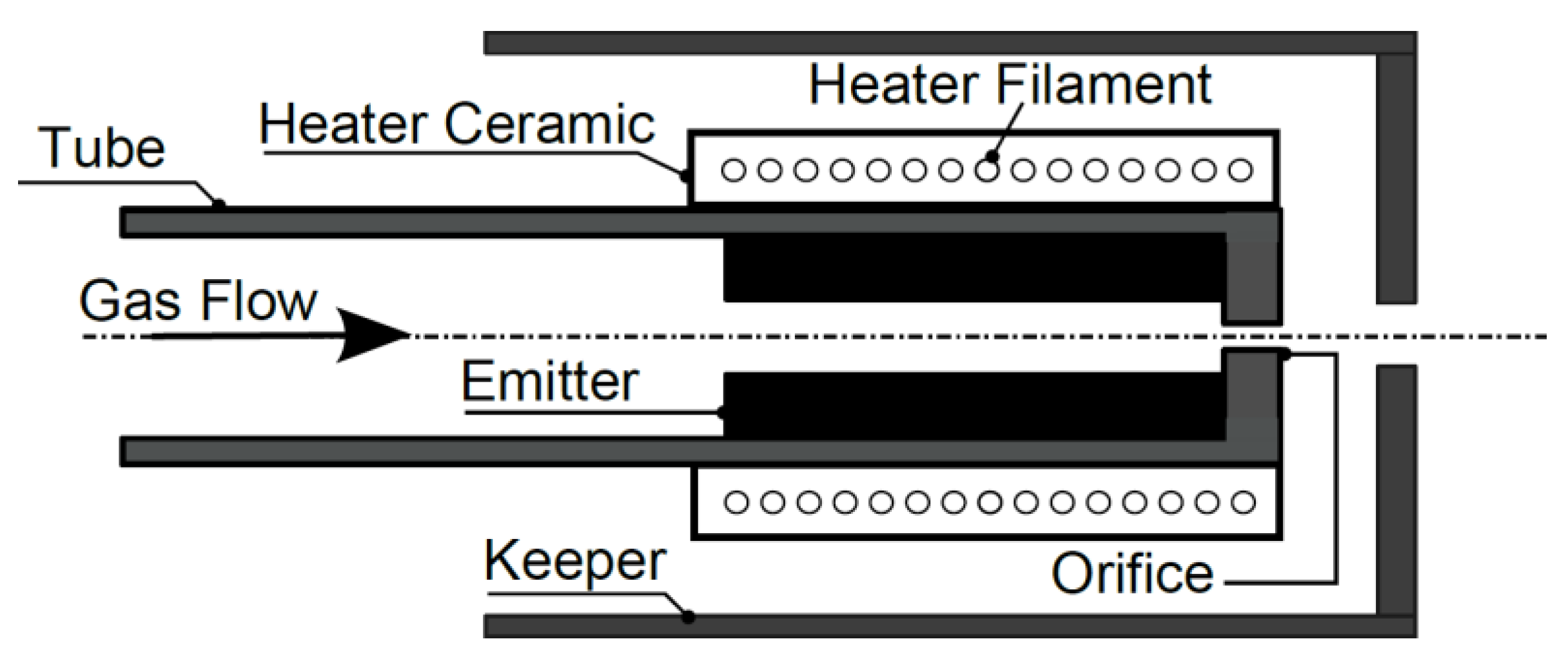
The cathode design follows the architecture of a typical orificed hollow cathode, schematically represented in
Figure 1. The cathode assembly includes an active thermionic electron emitter placed inside a tube wrapped by a heating filament (electrically insulated from the surrounding metal components by means of a ceramic material) and enclosed in an electrode, called a keeper, used to help the cathode ignition by applying a positive potential with respect to the inner tube. The keeper also protects the internal components from ion bombardment damage. The heater is used during the ignition phase to ease the discharge initiation by increasing the emitter temperature to thermionic emission values. Once the discharge is ignited, a plasma gap forms between the cathode and keeper orifices. The emitter surface is then maintained at the operating temperature by means of heating from the plasma and conduction from the orifice walls.
There are two main types of electron emitters used in space applications—the dispenser emitter and lanthanum hexaboride (LaB
6). The dispenser emitter relies on chemically activated metallic surfaces to produce the required electrons. It consists of a porous tungsten matrix impregnated with barium aluminate compounds under hydrogen atmosphere, providing a relatively low work function of about 2.1 eV [
6], which implies an operating temperature of about 1300 K to provide a current density in the order of 10 A/cm
2, as compared with up to 1900 K for LaB
6, the work function for which is 2.4−2.7 eV [
7].
The following section illustrates the development of HC1, starting from the first prototypes and arriving at the recent achievements in the framework of the µHETSat programme, an in-orbit validation mission jointly supported by the Italian Space Agency (ASI) and the European Space Agency (ESA) [
8], during which SITAEL completed the full ground qualification of the propulsion system.
2. HC1 Description
The HC1 technical specifications are summarized in
Table 1. The following discussion outlines the main activities performed to obtain the final cathode assembly.
The first cathode design was based on a LaB
6 emitter, due to the heritage gained at SITAEL in the development of higher current cathodes with this type of low work function material [
4]. Given the relatively high operating temperature, developing a heater to reach the emission temperatures of LaB
6 was a significant challenge, especially regarding the material selection. For this reason, a considerable effort was dedicated to a systematic experimental campaign to test different material combinations, with the aim of improving the heater performance and operational capabilities. The resulting heater configuration was adopted in the cathode assembly, proving the effectiveness in starting and operating the cathode in the expected range of currents and mass flow rates.
In a further endeavor to improve the cathode efficiency, the LaB
6 emitter was replaced by a barium-based dispenser (BaO-W) emitter, due to the lower operating temperature, which is particularly favorable in such a small device. The heater that had already been developed for the LaB
6 cathode version proved to be even more efficient in increasing the dispenser emitter temperature prior to ignition. At the same time, in the framework of the μHETSat program, the cathode’s mechanical structure underwent a redesign phase to achieve the robustness needed to survive environmental tests [
9].
The history of HC1, starting from different development models (DMs), passing through an engineering model (EM), and progressing to the latest version tested under the μHETSat program, is summarized in
Table 2. Two engineering qualification model (EQMs) and two proto flight model (PFMs) HC1 cathodes mounted on the μHETSat thruster unit successfully passed the performance, environmental, and thermal vacuum tests, approving them for the in-orbit demonstration.
2.1. Design Criteria
The main cathode dimensions derive from a reduced-order numerical model developed at SITAEL and validated throughout the years against experimental data [
10]. According to the theoretical model, the plasma formed inside the hollow cathode is ideally divided into three coupled regions: the emitter, the orifice, and the cathode-to-keeper gap. Equations expressing particle, momentum, and energy balances are numerically solved to compute the plasma properties in each region. Current density equations are introduced to estimate the voltage drop at the sheaths formed at the emitter and keeper surfaces for a given discharge current. The model assumes the formation of double sheaths at the boundary between the different regions of the cathode, being characterized by different plasma properties. A dedicated thermal model is coupled with the plasma models to estimate the power exchanges and the temperature profile along the cathode by means of power balance equations [
11].
The model was used to select the cathode dimensions (e.g., emitter internal diameter and length, orifice shape) after analyzing the results for each fixed geometry. A tradeoff was carried out between multiple factors, which include the overall geometrical envelope, the discharge power, the ratio between the emitter heating with respect to orifice heating, the emitter operating temperature, and the operating lifetime. The main criteria followed in the cathode design are listed hereinafter:
To ensure spot-mode operation, characterized by a well-focused and stable cathode plasma plume, in the predicted operating envelope;
To ensure a predominant contribution for the self-heating mode coming from the plasma as compared with conduction from the orifice, to limit its temperature, and in turn to limit its erosion;
To operate at an emitter temperature guaranteeing the lifetime requirements;
To select a reliable heater design in terms of thermal cycling, heating performance, materials compatibility, and properties;
To limit the cathode power consumption.
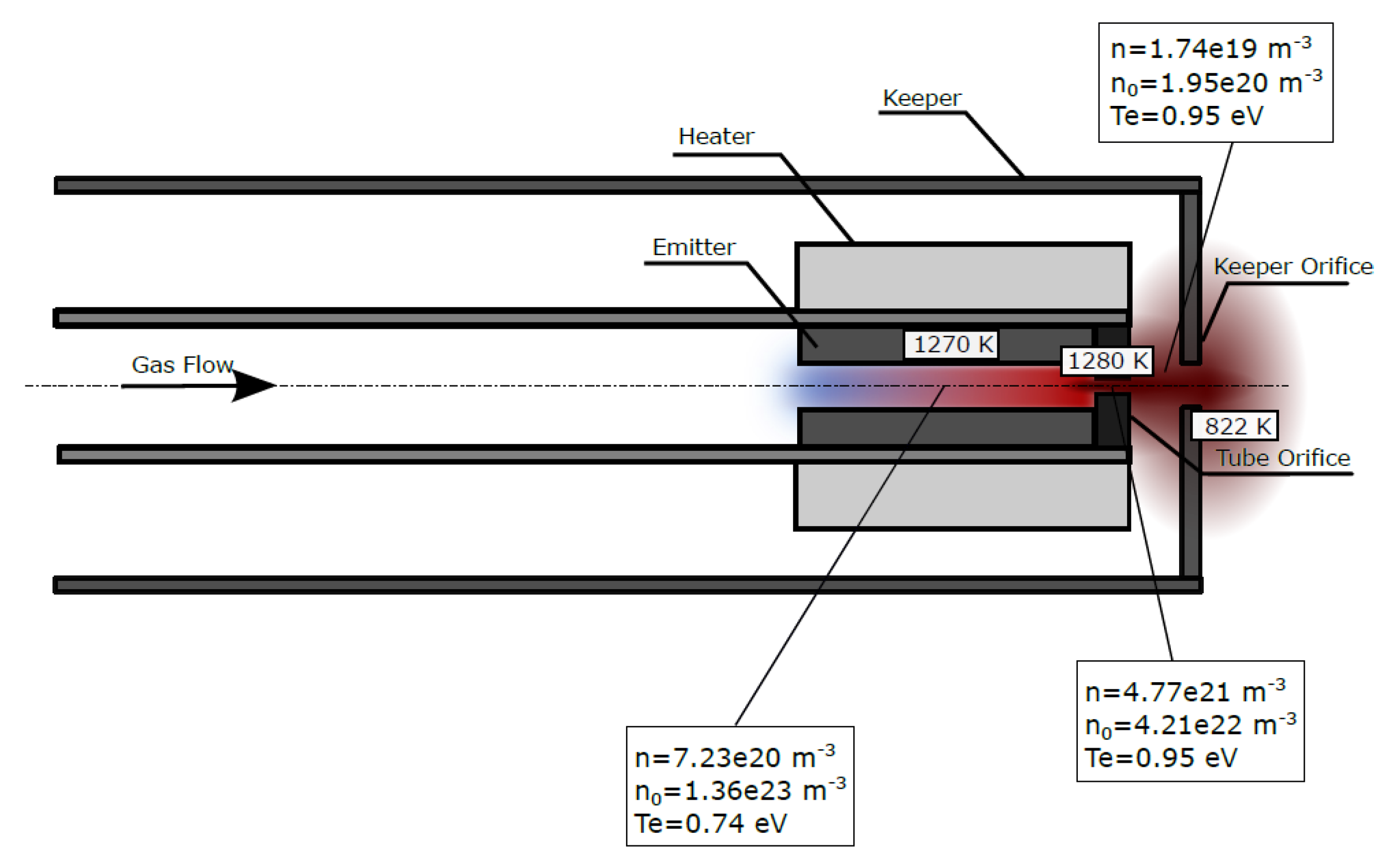
An example of the model results showing the plasma parameters in the different cathode regions and surface temperatures in reference points of the assembly is reported in
Figure 2. The results refer to operation at 0.5 A discharge current, 0.2 mg/s xenon mass flow rate, and with a floating keeper, corresponding to the nominal operating point in coupled configuration with HT100 for the µHETSat mission.
2.2. HC1 Emitter
The emitter is the active cathode element providing the required electrons by means of the thermionic emission mechanism. A dispenser S-type emitter was selected as the most commonly used emitter in electric space thrusters [
6]. The S-type emitter is made of a porous tungsten matrix impregnated with a barium–calcium–aluminate mixture (BaO/CaO/Al
2O
3 with a 4:1:1 molar ratio). Thermionic dispenser cathodes require an activation process to force the emitting compound to diffuse toward the inner surface of the emitter, which is performed before the very first ignition and after each atmospheric exposure to restart the cathode. The HC1 emitter is shaped as a hollow cylinder, the dimensions of which were selected with the aid of the numerical model following the design criteria described in
Section 2.1, according to the requirements in terms of the discharge current and mass flow rate listed in
Table 1. The emitter thickness was selected to ensure a long operation for versatile applications on multiple missions. The emitter lifetime was computed with the aid of a semiempirical formula relating the impregnated evaporation to the operating temperature resulting from the thermal model [
12]. According to the model results shown in
Figure 2, the predicted emitter lifetime at a surface temperature of 1270 K exceeds 10
6 h, which is well beyond the typical requirements of low-current hollow cathodes (up to 10
4 h).
2.3. HC1 Heater
The HC1 heater subassembly consists of a tungsten 3% rhenium (W3Re) filament wrapped around a ceramic electrically insulating element with the function of supporting the filament and transferring as much of the heating power coming from it as possible towards the tube on which the heater assembly is mounted. The heater filament consists of a coil with an additional wire wrapped around the leads to increase the effective cross-section, thus reducing the resistive power dissipation in the cathode’s rear to the advantage of the heating efficiency. The heater coil is in turn surrounded by a second insulating element with low thermal conductivity to reduce the power dissipation towards the outside surface in favor of the power directed to the tube. The use of high-temperature ceramic materials allows for the heater to be powered at a level that ensures the cathode ignition’s keeper voltage is below 100 V.
2.4. HC1 Mechanical Structure
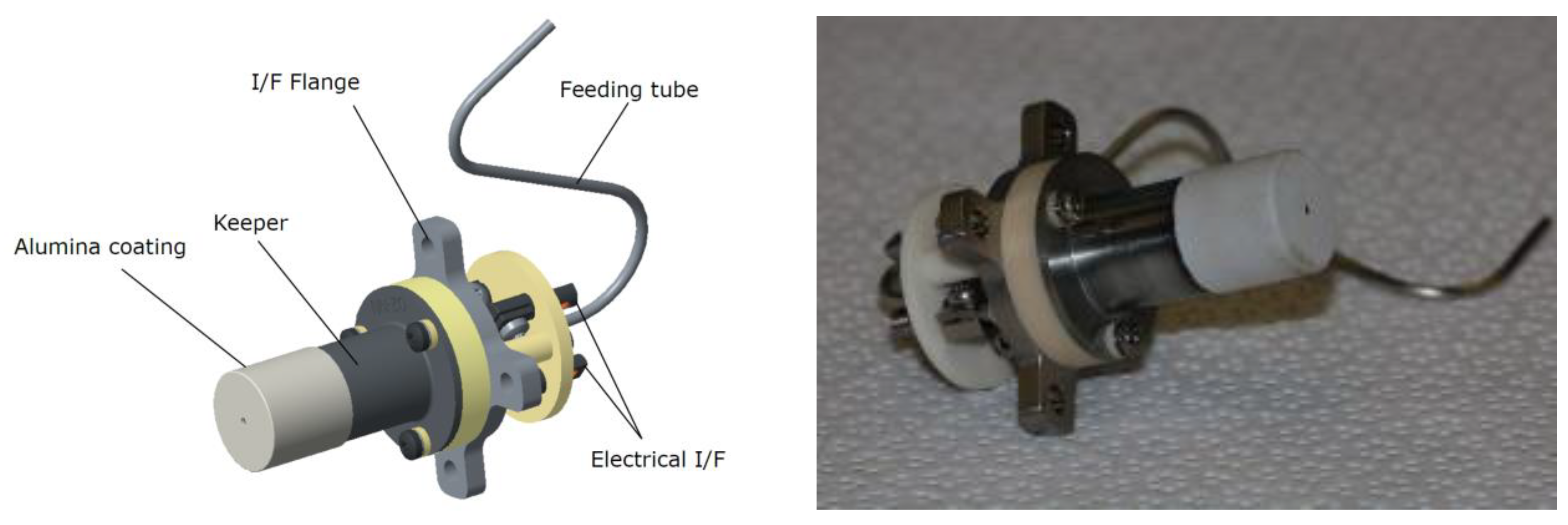
The HC1 mechanical structure includes several elements made of different materials, with some of them having multiple functions. The main cathode tube is a structural element, which also has the important function of being the negative electrode of the cathode assembly. A refractory metal was selected as the tube material due to the high operating temperatures and the relatively low thermal conductivity in order to limit the heat flux toward the base. Other structural components are indicated in
Figure 3. The interface flange, which is made of stainless steel, acts as a support for the cathode components, in addition to providing the propellant gas through the feeding tube. The keeper is made of a refractory metal alloy. To increase the cathode lifetime, the more exposed keeper surface is coated with alumina, since the lower sputtering yield of the alumina compared to the base material ensures a longer lifetime. The HC1 electrical interface includes dedicated connectors clamped to integrated protrusions in the keeper and cathode tube. In a similar way, the electrical connections on the heater are made directly on the leads.
4. Results
The following subsections summarize the main results achieved in the course of the cathode development, starting from its thermal characterization, continuing with the performance test, and concluding with the coupled tests, which were used for the full ground qualification of the HT100 thruster unit.
4.1. Cathode Thermal Characterization
Preliminary tests were performed to evaluate the heater behavior and efficiency in the hollow cathode assembly. The heater robustness was demonstrated during a thermal cycling test, which reached more than 5000 on–off cycles, carried out by switching the heater on at 7 A (maximum current level for cathode ignition), switching it off after 5 min, and waiting 20 min for it to cool down.
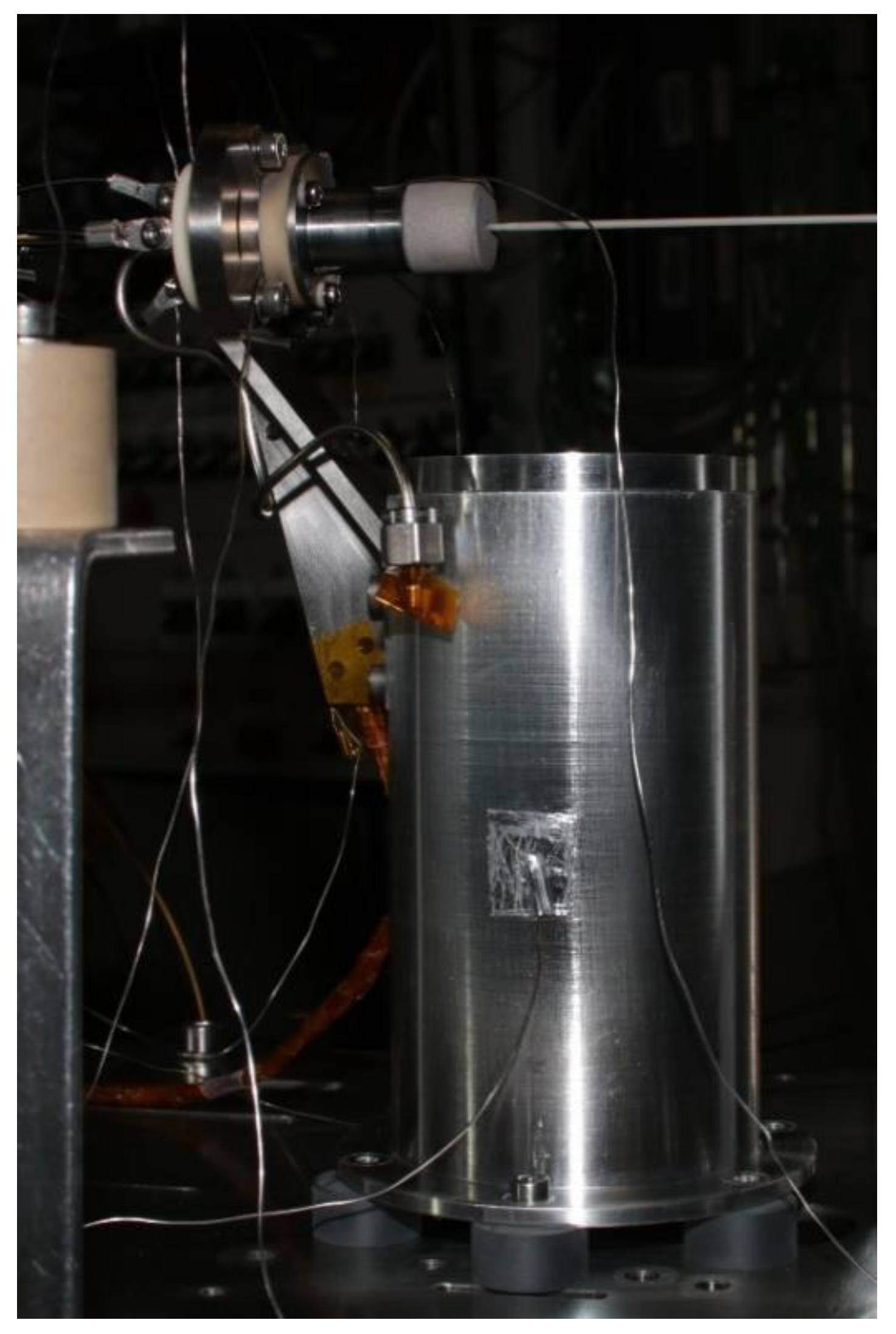
The heater efficiency in warming up the emitter was evaluated during a dedicated thermal test, where the cathode was equipped with several thermocouples to obtain a temperature map as a function of the heater power. The thermal test setup is shown in
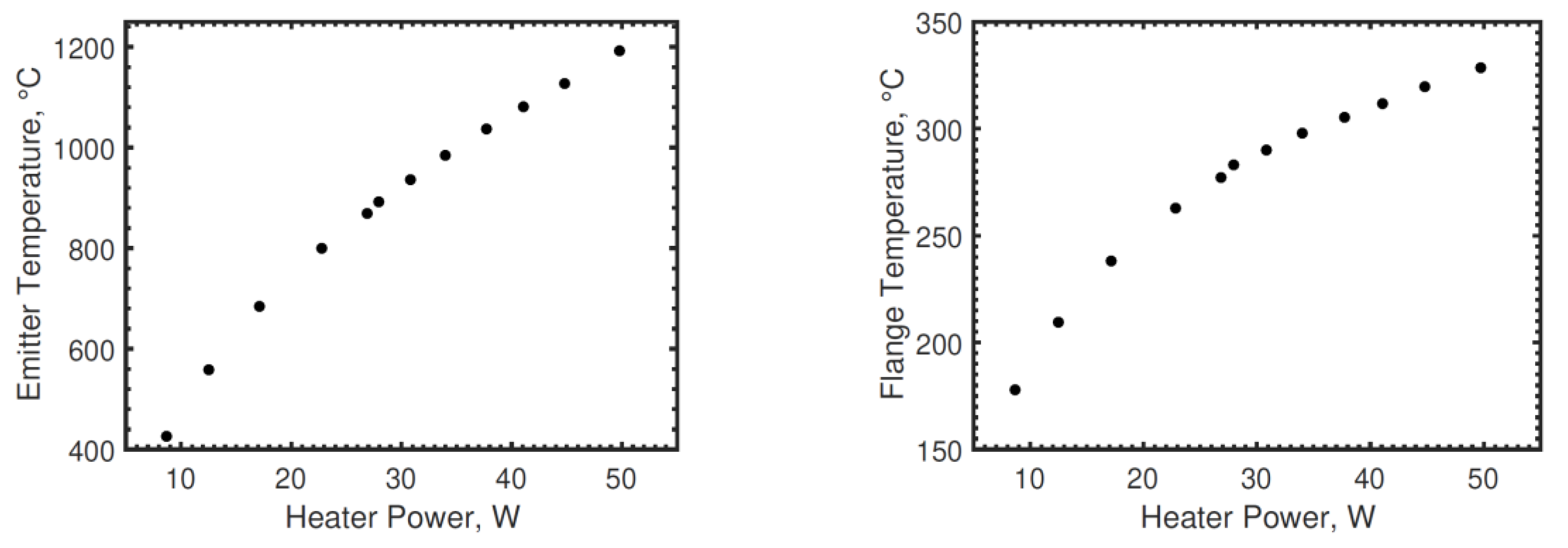
Figure 5, where the cathode is connected to a thruster dummy model by means of a dedicated bracket. An N type thermocouple measured the emitter temperature, with the results shown in
Figure 6 left—a heater current of 6.7 A corresponding to approximately 50 W of heater power allowed for the emitter to reach a steady-state temperature of about 1200 °C.
Figure 6 (right) shows the temperature at the interface flange, which is usually monitored during functional tests where the emitter temperature is not available. In the following figures, the measurement error is included in the marker size.
The information gained during the cathode thermal test allowed a heating sequence to be identified, namely a stepwise increase in the heater current, to reach the proper emitter temperature values needed for its activation.
4.2. Cathode Performance Tests
The barium-based emitter requires an activation process to force the emitting compound to diffuse toward the inner surface of the emitter. The reaction of the impregnant with the tungsten matrix releases barium atoms, which pass through the pores to combine with oxygen, thus creating the superficial monolayer of BaO [
6]. In addition, the emitter must be allowed to soak at two temperatures long enough to allow complete out-gassing of the water vapor.
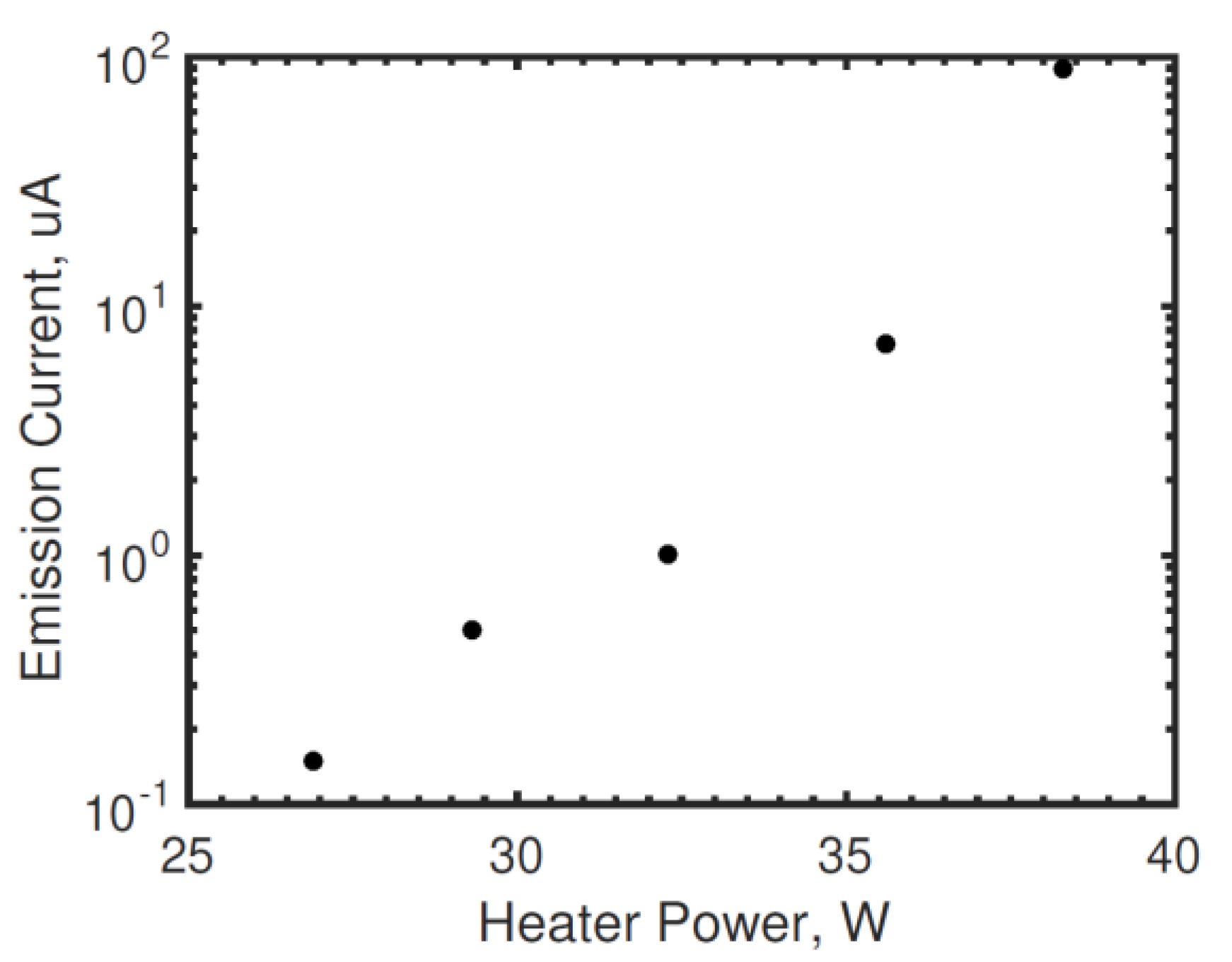
With the emitter temperature mapping obtained from the thermal test, the heater power values required to reach the two soak temperatures were identified and included in the cathode activation procedure. This procedure lasts several hours and must be performed each time the cathode is ignited after air exposure, as well as for the very first ignition. During the heating ramp, the cathode starts emitting an electron current due to the thermionic effect. In this phase, the emitted current was measured with the aid of a multimeter, as the keeper was biased relative to the cathode at 100 V. An example of the measured values is shown in
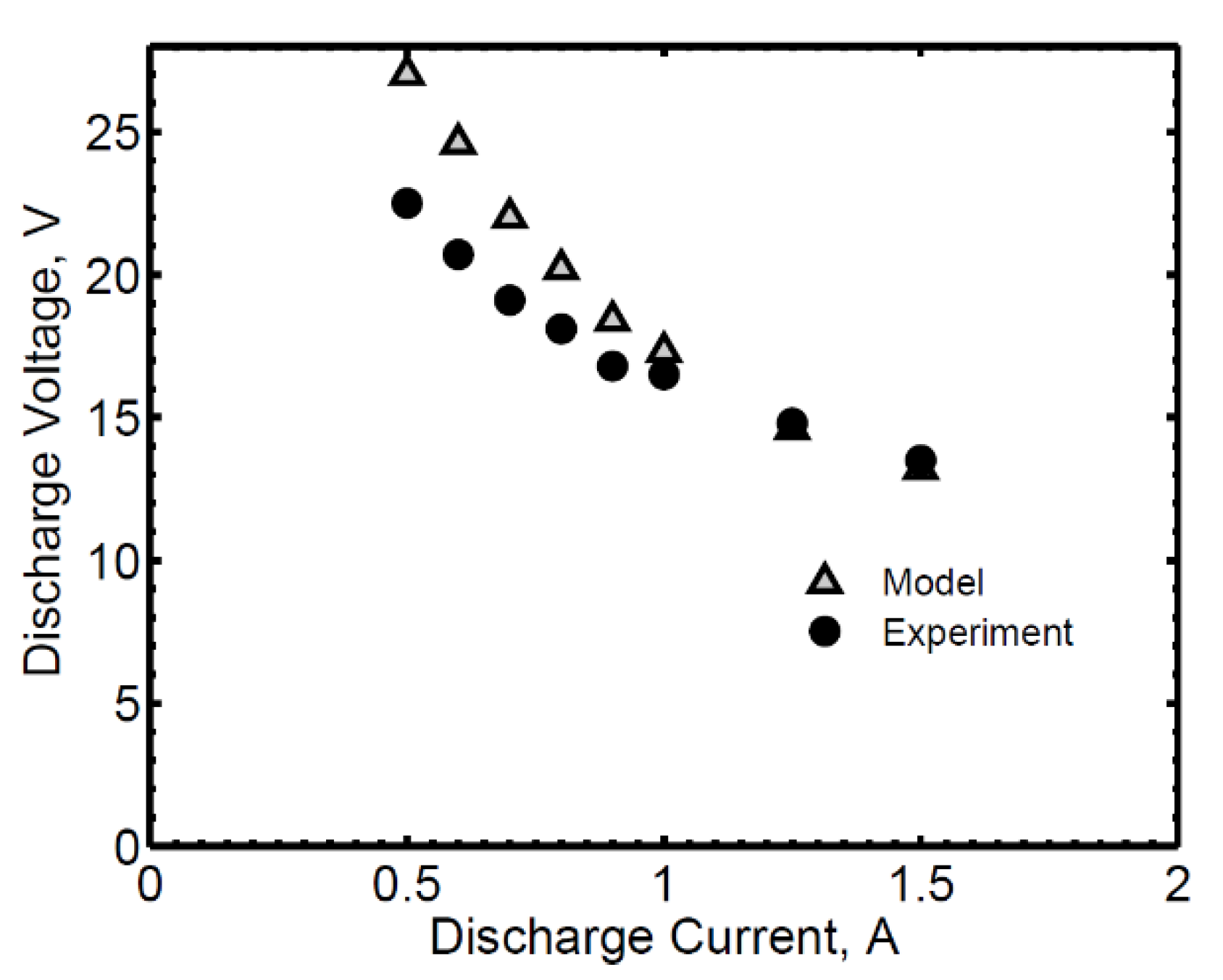
Figure 7, where the emitted current is reported as a function of heater power. Variability in the emitted current values of about 20% among different cathodes was observed, which is ascribed to the measurement uncertainties of such low current values. Nevertheless, the emission curve remains an important indication in terms of the emitted current trend with increasing heater power to evaluate the success of the cathode activation. After the activation phase, the cathode could be ignited, with a heater power of less than 50 W and a mass flow rate of between 0.1 and 0.2 mg/s (multiple ignitions were found to be successful in the indicated flow range). A keeper voltage of 100 V is normally applied before setting the final value of the heater power, and lower values (<50 V at the beginning of life) were found to be sufficient for ignition. The cathode’s electrical characteristics with 0.1 mg/s Xe are reported in
Figure 8, together with the corresponding theoretical results. The model is in excellent agreement with the experimental data at the higher currents, whereas a maximum difference of about 4.5 V is found at 0.5 A [
13].
4.3. Coupled Tests with HT100
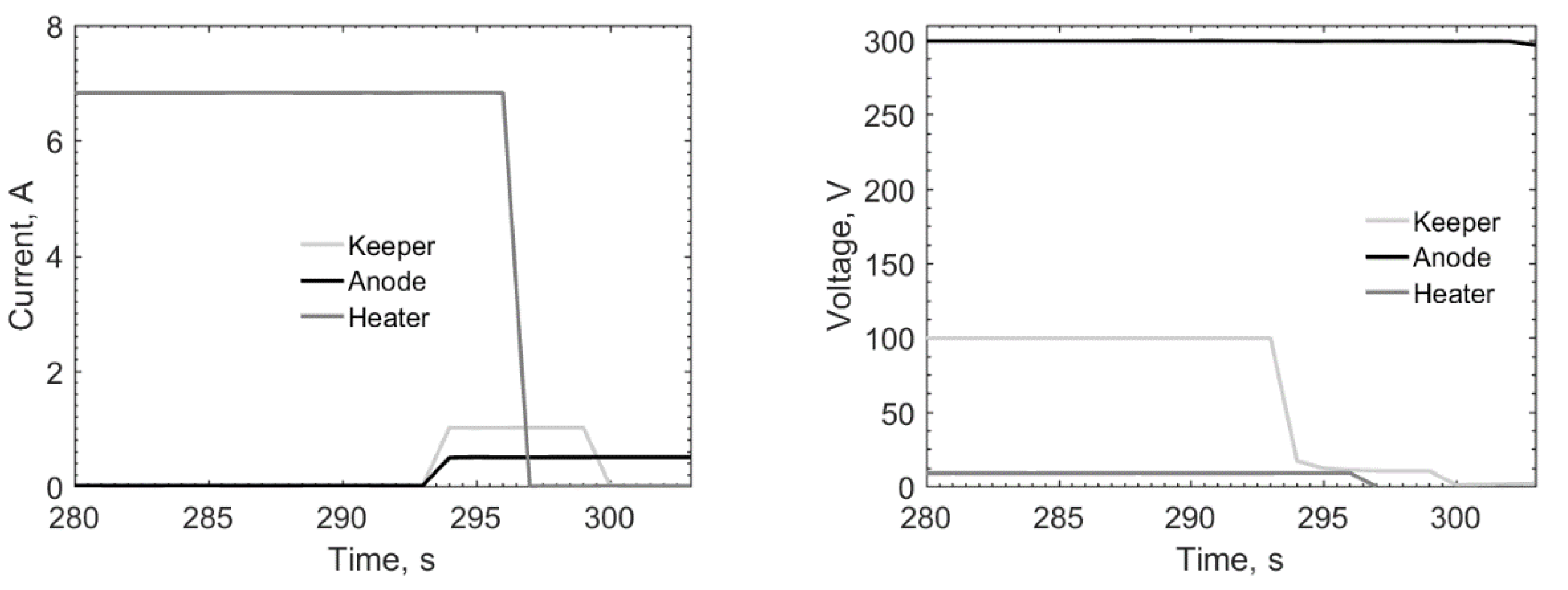
The typical ignition sequence of the HC1 in coupled configuration with HT100 is reported in
Figure 9, in terms of the current and voltage trends of the heater, keeper, and thruster anode. With the gas flowing in both the cathode and anode units, a keeper voltage of 100 V is applied, together with an anode voltage of 300 V, then the heater is switched on, supplying it with a current of 6.8 A. Correspondingly, the heater voltage increases, reaching a steady-state value of about 7 V, resulting in slightly less than 50 W being supplied to the heater. After about 5 min, the discharge ignites and a keeper current of 1 A (limited value set on the power supply) is reached, along with an anode current of about 0.5 A (the anode being in voltage control mode). As soon as the cathode is ignited, the heater is switched off and the self-mode operation is maintained by the plasma heating mechanisms [
13]. The keeper voltage during the starting transient drops from the applied value of 100 V to a steady-state value of about 14 V, corresponding to the characteristic voltage drop of the cathode at the operating point with a 1 A keeper current and 0.2 mg/s Xe. After switching the heater off, the keeper is also switched off and the discharge is maintained between the anode and cathode tube.
Within the framework of the µHETSat program, during the qualification test campaign for the 100 W thruster unit (TU) composed of the HT100 anode unit and two HC1 cathodes, the cathode met the TU requirements for thrust, specific impulse, and power consumption. The performance values at the nominal operating point are about 7 mN of thrust, 1020 s of specific impulse, and 140 W of power consumption. Shock and vibration tests were successfully completed, as described in [
8], proving the cathode with mechanical robustness in withstanding the typical launch loads and vibrations required by the final application.
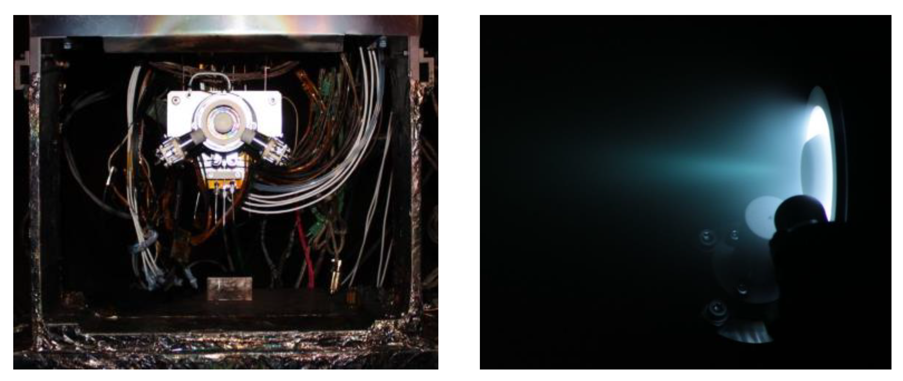
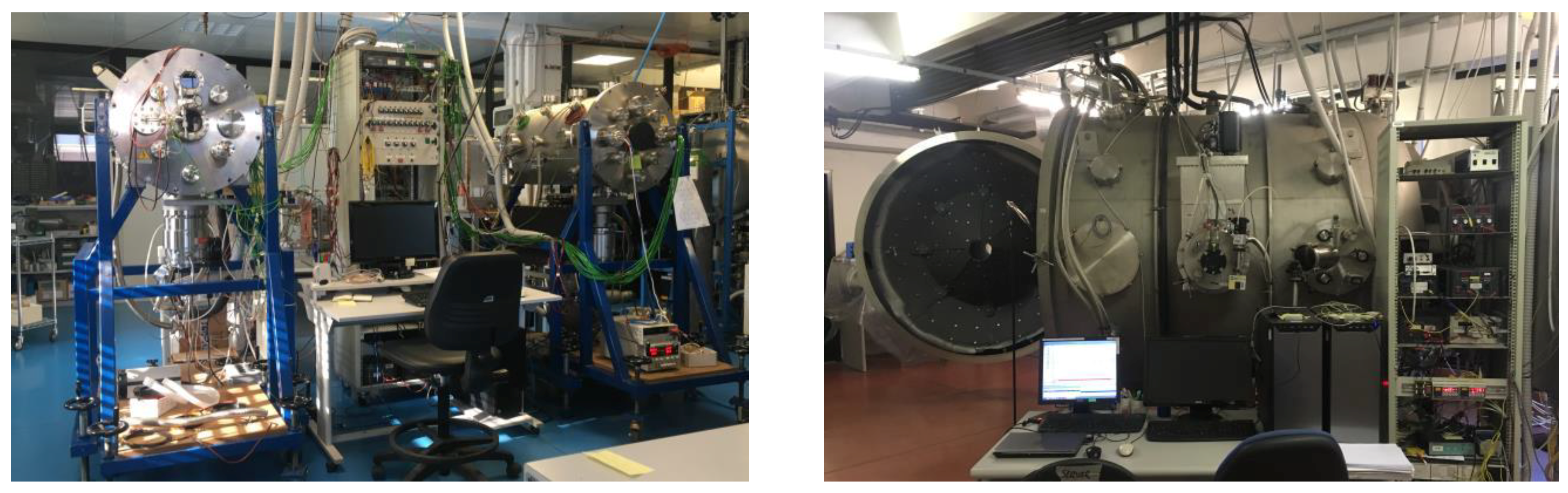
Figure 10 shows the TU mounted on the thrust balance before a coupling test (left) and during operation (right).
5. Conclusions
This paper presented the significant advances obtained at SITAEL in the development of a low-current hollow cathode, named HC1. After several years dedicated to obtaining a robust design, important results were reached, paving the way for consolidated use of this cathode coupled with HT100, the Hall thruster it was conceived for, in ambitious space missions. Activities are in progress towards the in-orbit demonstration of HC1 operating with HT100. The other objectives were the evaluation of different materials, manufacturing techniques, and propellant selection to meet the needs and increasing challenges of the constantly growing electric propulsion market.


