Aeroelastic Wing Planform Design Optimization of a Flutter UAV Demonstrator

Abstract
1. Motivation of Flexible Wing Technologies
Aeroelastic Problem Description
2. Parametric Elastic Aircraft Model
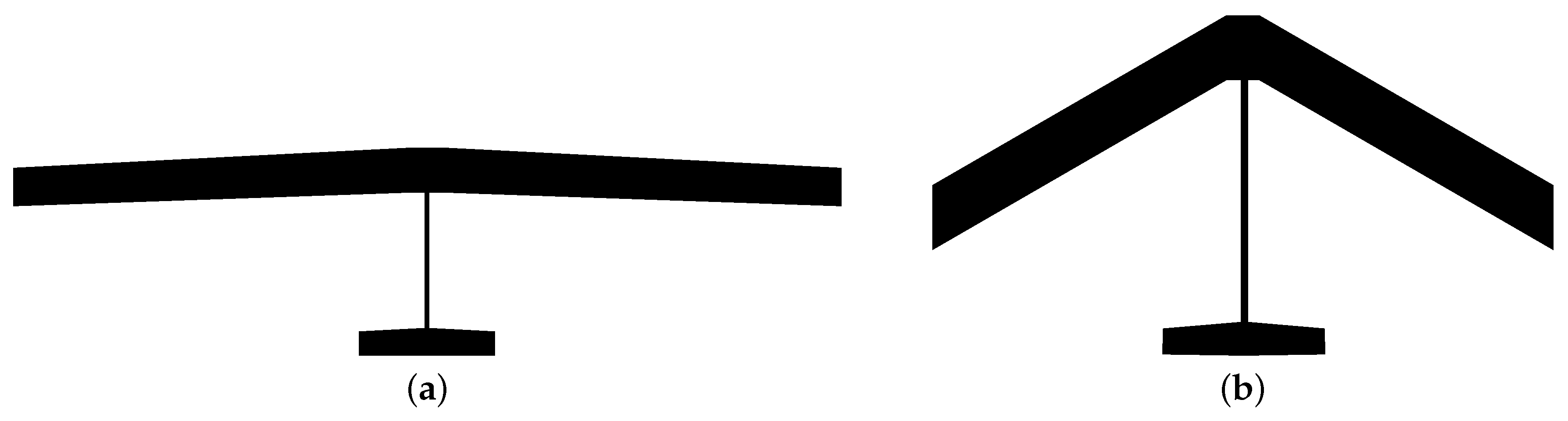
2.1. Wing Planform Parameter and Structural Design
- Ply Count: usually limited to a minimum number for production reasons.
- Ply thickness: limited by layers with a minimum thickness available on the market ()
- The GFRP plies have a Young’s modulus in the fiber direction of , and are therefore less stiff than CFRP.
- Thin plies are prone to buckling. The foam core sandwich design increases bending stiffness significantly (parallel axis theorem) with a moderate growth in structural mass compared to a full monolithic design.
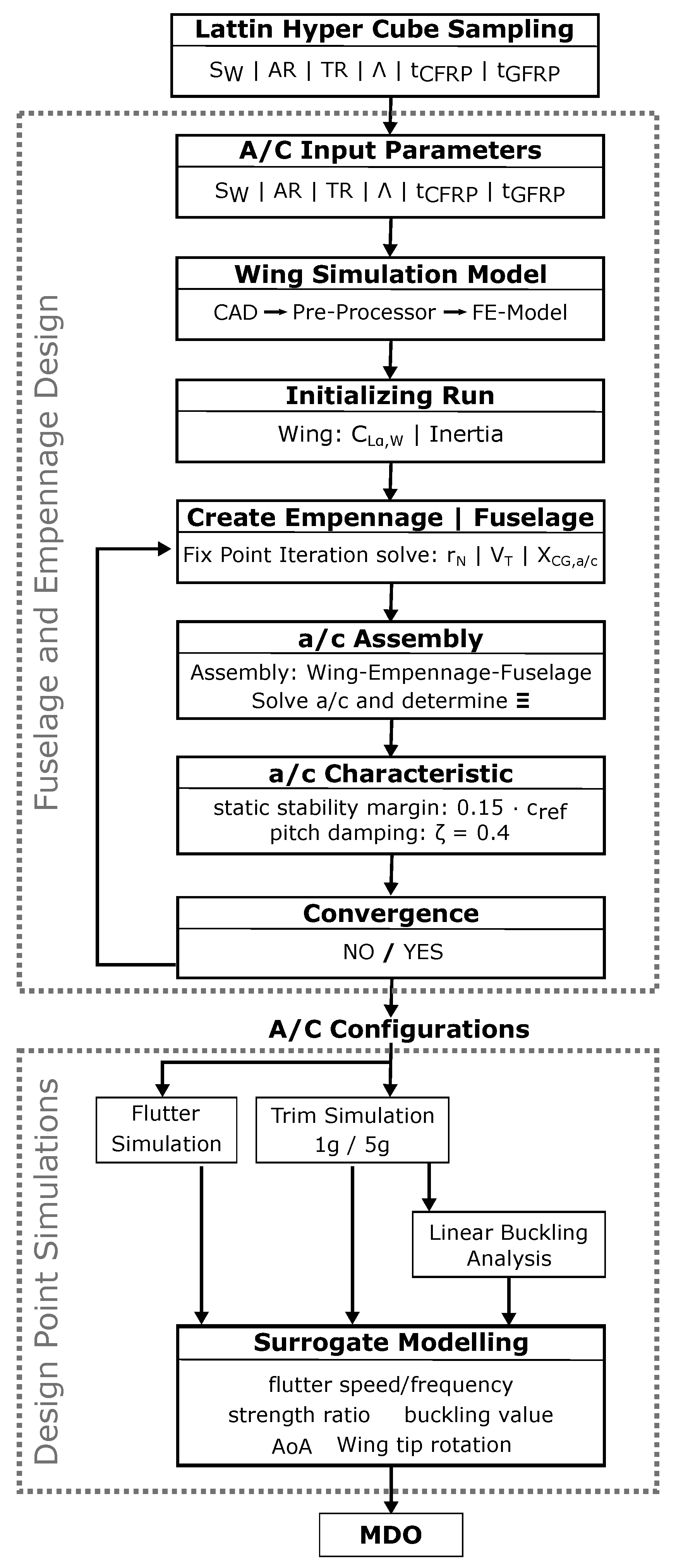
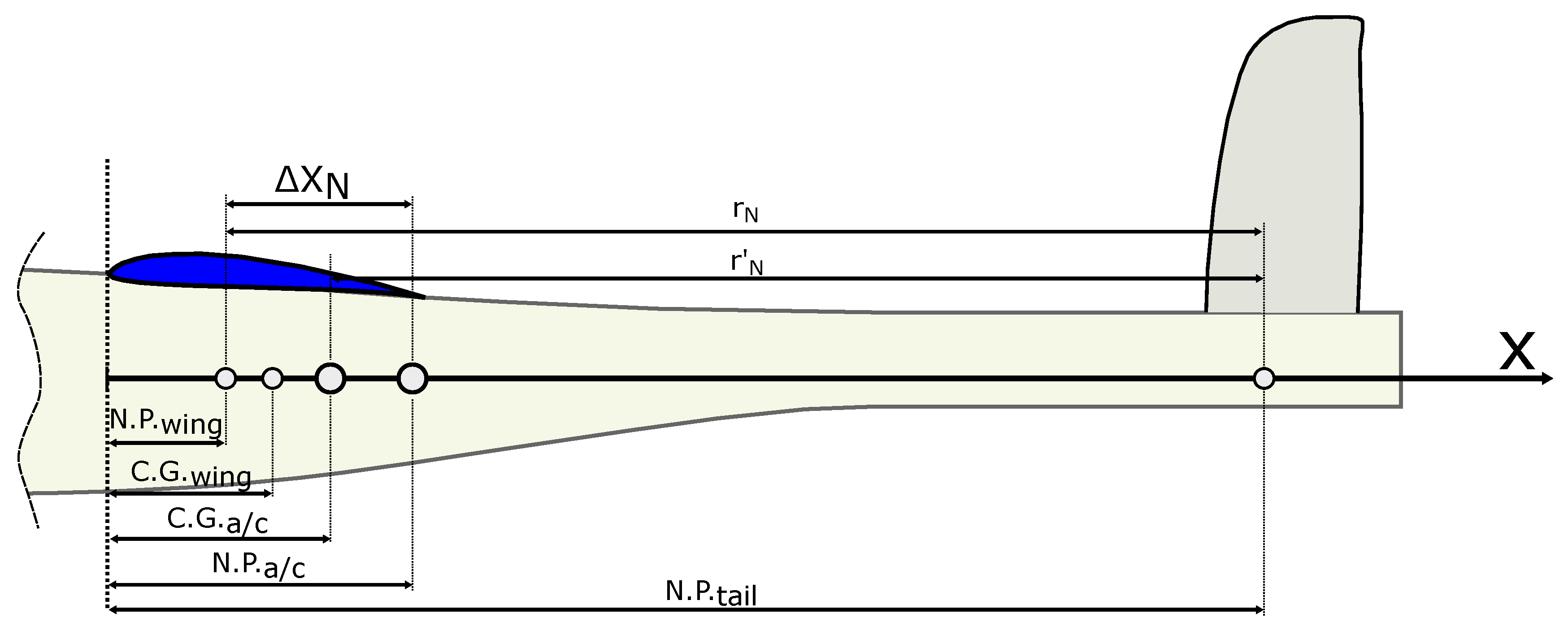
2.2. Parametric Empennage and Fuselage Design Process
- Static flight stability margin ;
- Relative pitch Damping .
- : lever arm of the tail.
- : Empennage Volume, defined as , where the empennage reference area is.
- : Center of Gravity full aircraft.
3. Mathematical Optimization Statement and Surrogate Modeling
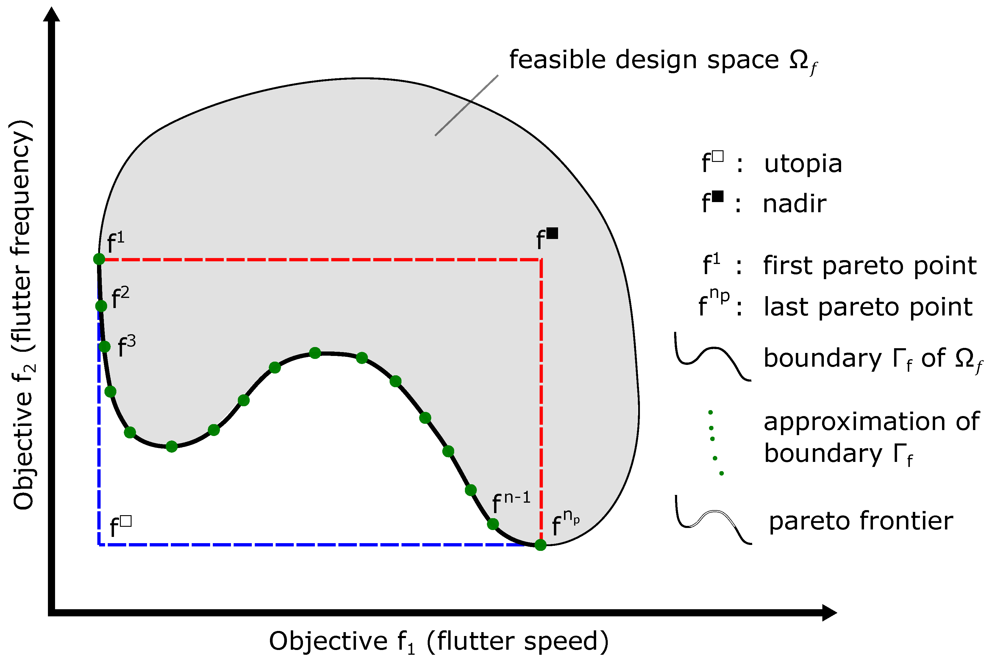
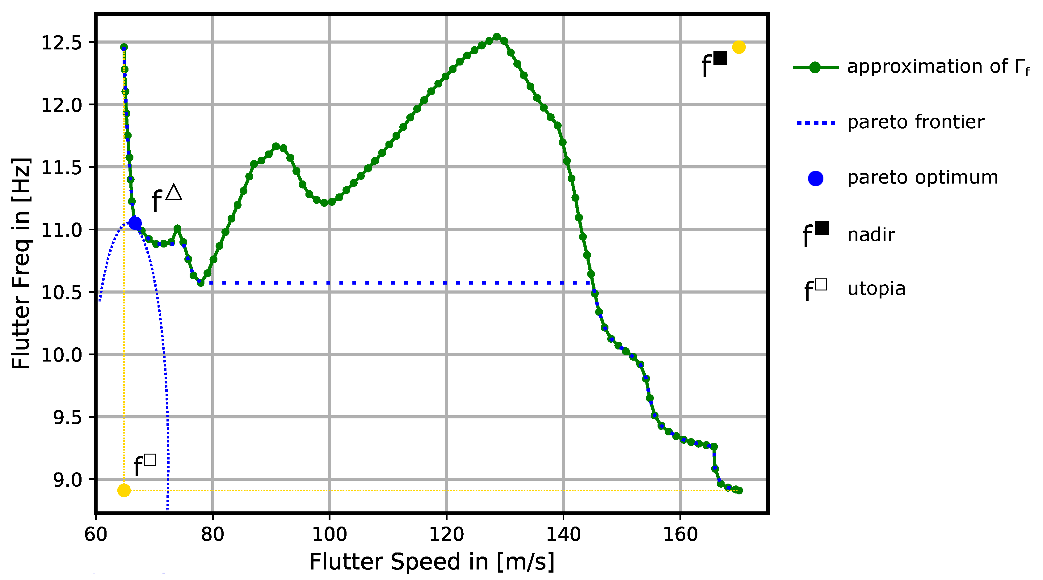
3.1. Multi-Objective Optimization Technique
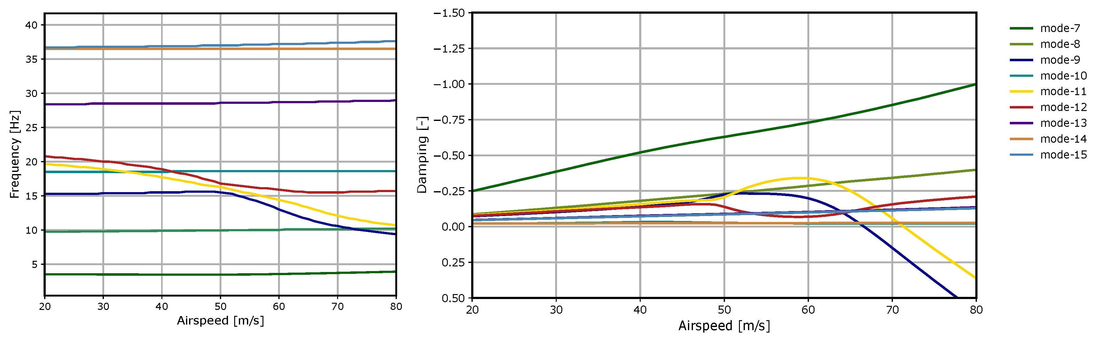
3.2. Aeroelastic Design Optimization
3.3. Surrogate Model Construction
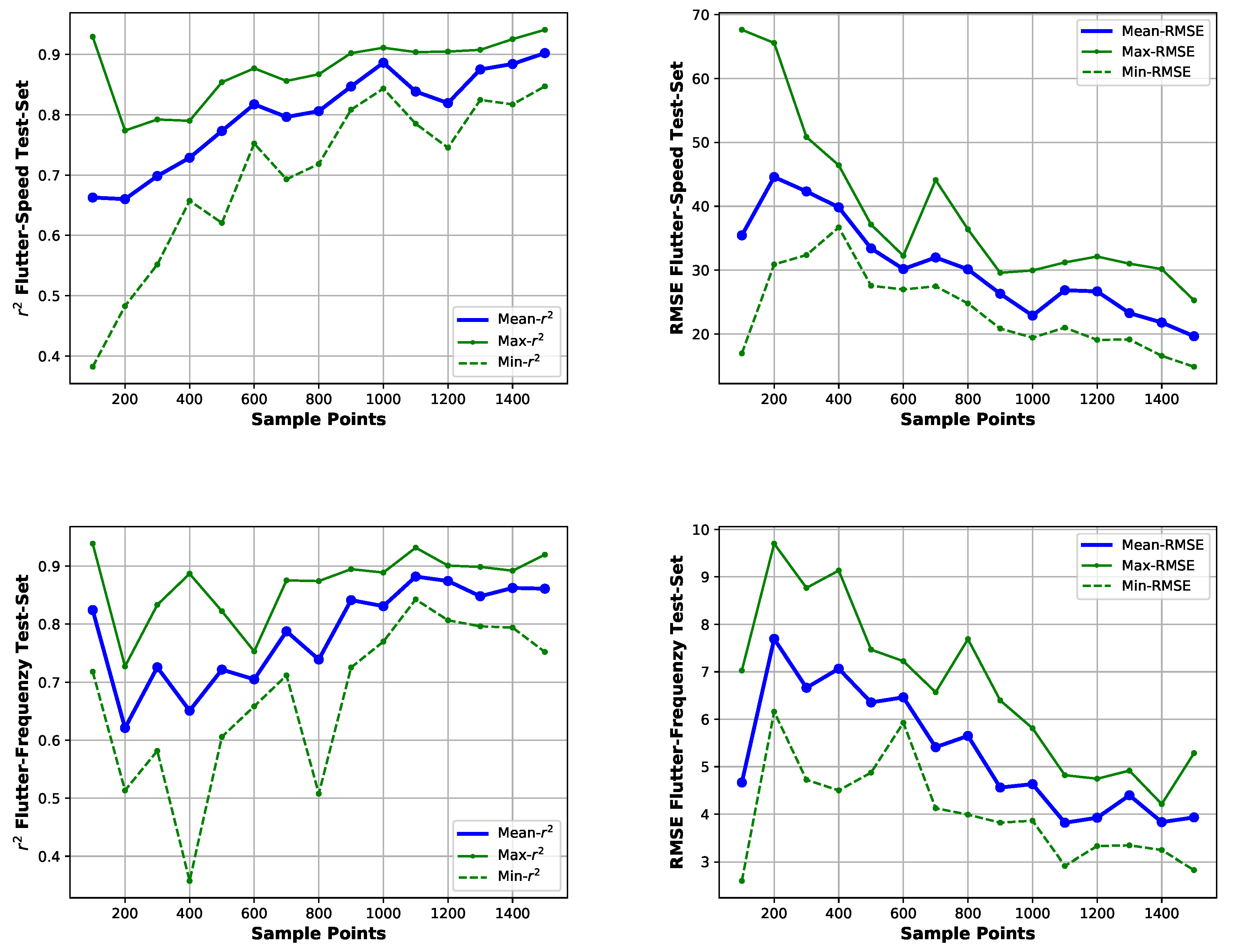
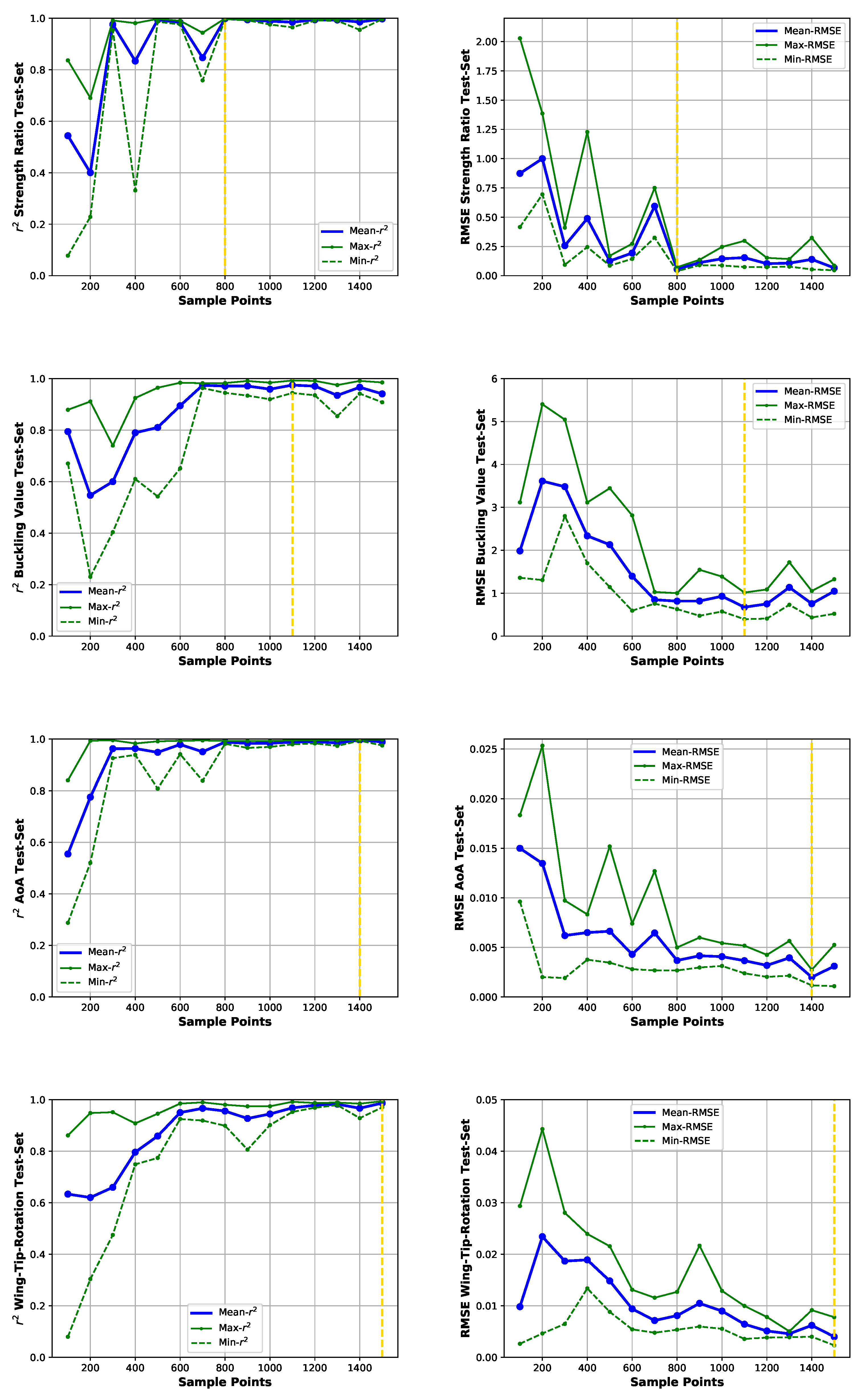
3.4. Surrogate Model Cross-Validation
4. Aircraft Conceptual Optimization Result
Multi-Objective Optimization Results
5. Summary and Conclusions
Author Contributions
Funding
Conflicts of Interest
Abbreviations
| Aspect Ratio | |
| Root Mean Square Error | |
| Area Ratio | |
| Pitch Moment Alpha Derivative | |
| Pitch Moment Pitch Rate Derivative | |
| Wing Area (m) | |
| Empennage Area (m) | |
| Carbon Fiber Reinforced Polymer | |
| t | Play Thickness in (mm) |
| Center of Gravity | |
| Taper Ratio | |
| Reference Chord Length (m) | |
| Reference Airspeed (m/s) | |
| Free Stream Velocity (m/s) | |
| Trim Point Velocity (m/s) | |
| Lift Coefficient | |
| Empennage Volume (m) | |
| Lift Gradient | |
| x | Optimization Design Vector |
| Doublet, Vortex Lattice Method | |
| Boundary Curves | |
| Static Stability Margin | |
| Nadir, Utopia Point | |
| Relative Pitch Damping | |
| Pareto Point | |
| Scalarization Parameter | |
| Aircraft Inertia (kgm) | |
| Wing Sweep | |
| Neutral Point | |
| Absolute Downwash Correction | |
| Tail lever arm (m) | |
| Absolute Damping | |
| Correlation Coefficient | |
| Feasible Design Space | |
| Eigenfrequency (Hz) |
References
- Cheelhaase, J.; Grimme, W.; O’Sullivan, M.; Naegler, T.; Klötzke, M.; Kugler, U.; Scheier, B.; Standfuß, T. Klimaschutz im Verkehrssektor; Aktuelle Beispiele aus der Verkehrsforschung. Wirtschaftsdienst 2018, 98, 655–663. [Google Scholar] [CrossRef]
- Kenway, G.K.; Martins, J.R. Multipoint High-Fidelity Aerostructural Optimization of a Trasport Aircraft Configuration. J. Aircr. 2014, 51, 144–160. [Google Scholar] [CrossRef]
- Martins, J.; Kennedy, G.; Kenway, G.K. High Aspect Ratio Wing Design: Optimal Aerostructural Tradeoffs for the Next Generation of Materials. In Proceedings of the 52nd Aerospace Sciences Meeting, National Harbor, MD, USA, 13–17 January 2014. [Google Scholar]
- Krueger, W.; Dillinger, J.; Breuker, R.; Haydn, K. Investigations of passive wing technologies for load reduction. CEAS 2019, 10, 977–993. [Google Scholar] [CrossRef]
- Opgenoord, M.M.J. Design Methodology for Aeroelastic Tailoring of Additively Manufactured Lattice Structures Using Low-Order Methods. AIAA J. 2019, 57, 4903–4914. [Google Scholar] [CrossRef]
- Lampl, T.; Hornung, M. An Integrated Design Approach for Advanced Flight Control Systems with Multifunctional Flight Control Devices; AIAA Aviation: Atlanta, GA, USA, 2018. [Google Scholar]
- Livne, E. Aircraft Active Flutter Suppression: State of the Art and Technology Maturation Needs. J. Aircr. 2018, 55, 410–452. [Google Scholar] [CrossRef]
- Certification Specification and Acceptable Means of Compliance for Large Aeroplanes CS-25-Amendment 24. Available online: https://www.easa.europa.eu/sites/default/files/dfu/CS-25%20Amendment%2024.pdf (accessed on 6 April 2020).
- NASA—Air Force Research Laboratory. X56A Multi-Utility Technology Testbed. Available online: nasa.gov/centers/armstrong/research/X-56/index.html (accessed on 6 February 2018).
- FLEXOP Consortium. Flutter Free Flight Envelope Expansion for Economical Performance Improvement. Available online: https://flexop.eu (accessed on 6 February 2018).
- Stahl, P.; Sendner, F.M.; Roessler, C.; Hornung, M.; Hermanutz, A. Mission and Aircraft Design of FLEXOP Unmanned Flying Demonstrator to Test Flutter Suppression within Visual Line of Sight; AIAA Aviation: Denver, CO, USA, 2017. [Google Scholar]
- Schmidt, D.; Danowsky, B.; Seiler, P.J.; Kapania, R. Flight-Dynamics, Flutter Analysis, and Control of MDAO-Designed Flying-Wing Research Drones; AIAA-SciTech: San Diego, CA, USA, 2019. [Google Scholar]
- Beranek, J.; Nicolai, L.; Buonanno, M.; Burnett, E.; Atkinson, C.; Holm-Hansen, B.; Flick, P. Conceptual Design of a Multi-utility Aeroelastic Demonstrator. In Proceedings of the AIAA Multidisciplinary Analysis Optimization Conferecne, Fort Worth, TX, USA, 13–15 September 2010. [Google Scholar]
- Gudmundsson, S. General Aviation Aircraft Design; Butterworth-Heinemann: Oxford, UK, 2014; Chapter 11. [Google Scholar]
- Schlichting, H.; Truckenbrodt, E. Aerodynamik des Flugzeuges; Springer: Berlin/Heidelberg, Germany, 2001; Chapters 5 and 6. [Google Scholar]
- Aeroelastic Analysis User’s Guide; MSC/Software Corporation: Newport Beach, CA, USA, 2018.
- Pusch, M.; Ossmannm, D.; Luspay, T. Structured Control Design for a Highly Flexible Flutter Demonstrator. Aerospace 2019, 3, 27. [Google Scholar] [CrossRef]
- Pereyra, V. Fast computation of equispaced Pareto manifolds and Pareto fronts for multiobjective optimization problems. Math. Comput. Simul. 2009, 76, 1935–1947. [Google Scholar] [CrossRef]
- Schatz, M.; Hermanutz, A.; Horst, B. Multi-criteria optimization of an aircraft propeller considering manufacturing. Struct. Multidiscip. Optimiz. 2016, 55, 899–911. [Google Scholar] [CrossRef]
- Mishra, S.K. Topics in Nonconvex Optimization; Springer: New York, NY, USA, 2011. [Google Scholar]
- Schittkowski, K. A robust implementation of a sequential quadratic programming algorithm with successive error restoration. Optimiz. Lett. 2011, 2, 283–296. [Google Scholar] [CrossRef]
- Fisher, R.A. The Design of Experiments; Oliver and Boyd: Edinburgh, UK, 1935; Chapter 5. [Google Scholar]
- Forrester, A.; Sobester, A.; Keane, A. Engineering Design via Surrogate Modelling; Wiley: Hoboken, NJ, USA, 2008; Chapters 1, 2, 3, 6. [Google Scholar]
- Hoerl, E.; Kennard , R.W. Ridge Regression: Biased Estimation for Nonorthogonal Problems. Technometrics 1970, 12, 55–67. [Google Scholar] [CrossRef]
- Wuestenhagen, M.; Kier, T.; Meddaikar, Y.M.; Pusch, M.; Ossmann, D.; Hermanutz, A. Aeroservoelastic Modeling and Analysis of a Highly Flexible Flutter Demonstrator, AIAA Aviation: Atlanta, GA, USA, 2018.
- Mardanpour, P.; Izadpanahi, E.; Rastkar, S. Constructal Design of Aircraft: Flow of Stresses and Aeroelastic Stability. AIAA J. 2019, 57, 4393–4405. [Google Scholar] [CrossRef]


| x | Unit | ||
|---|---|---|---|
| S | m | ||
| AR | − | ||
| TR | − | ||
| deg | |||
| mm | |||
| mm |
| RMSE | Max Absolute Error | |
|---|---|---|
| flutter speed (m/s) | 1.80 | 5.12 |
| flutter freq (Hz) | 0.689 | 1.412 |
| strenght ratio (-) | 0.013 | 0.028 |
| buckling value (-) | 0.098 | 0.571 |
| AoA | ||
| Wing-Tip Rotation |
| Flutter Speed | Flutter Frequency | |
|---|---|---|
| optimization objective flutter speed | ||
| optimization objective flutter frequency |
| Flutter Speed | Flutter Frequency | |
|---|---|---|
| surrogate model results | ||
| verification results |
| Min Flutter Speed Configuration | Min Flutter Frequency Configuration | Pareto Optimal Configuration | |
|---|---|---|---|
| Wing Area | 4.0 | 3.6 | 4.0 |
| Aspect Ratio | 22.0 | 9.5 | 20.1 |
| Taper Ratio | 0.84 | 1.0 | 0.95 |
| Wing Sweep | 2.2 | 30.0 | 3.3 |
| 0.2 | 0.02 | 0.2 | |
| 0.05 | 0.2 | 0.05 | |
| Total UAV weight | 64.1 | 64.2 | 63.5 |
| Wing Span (m) | 9.38 | 5.848 | 8.971 |
| Empennage Leaver Arm | 1.972 | 2.249 | 1.9801 |
| 5g max wing tip -deflection (mm) | 231.4 | 172.6 | 208.1 |
© 2020 by the authors. Licensee MDPI, Basel, Switzerland. This article is an open access article distributed under the terms and conditions of the Creative Commons Attribution (CC BY) license (http://creativecommons.org/licenses/by/4.0/).
Share and Cite
Hermanutz, A.; Hornung, M. Aeroelastic Wing Planform Design Optimization of a Flutter UAV Demonstrator. Aerospace 2020, 7, 45. https://doi.org/10.3390/aerospace7040045
Hermanutz A, Hornung M. Aeroelastic Wing Planform Design Optimization of a Flutter UAV Demonstrator. Aerospace. 2020; 7(4):45. https://doi.org/10.3390/aerospace7040045
Chicago/Turabian StyleHermanutz, Andreas, and Mirko Hornung. 2020. "Aeroelastic Wing Planform Design Optimization of a Flutter UAV Demonstrator" Aerospace 7, no. 4: 45. https://doi.org/10.3390/aerospace7040045
APA StyleHermanutz, A., & Hornung, M. (2020). Aeroelastic Wing Planform Design Optimization of a Flutter UAV Demonstrator. Aerospace, 7(4), 45. https://doi.org/10.3390/aerospace7040045