A Design for Qualification Framework for the Development of Additive Manufacturing Components—A Case Study from the Space Industry


Abstract
1. Introduction
| Validation: | process which demonstrates that the product is able to accomplish its intended use in the intended operational environment. |
| Verification: | process which demonstrates through the provision of objective evidence that the product is designed and produced according to its specifications and the agreed deviations and waivers and is free of defects. Verification is a pre-requisite for validation. |
| Qualification: | that part of verification which demonstrates that the product meets specified qualification margins. |
1.1. Challenges with Qualification of Additive Manufacturing Parts
1.2. Product Development with Additive Manufacturing
- Use established material design data for a qualified AM process that can be used as reference for any product to be manufactured with the same AM process.
- Use established material design data for a known material (possibly different from AM) as reference and show that this data can be used as minimum properties for the AM material in the design (e.g. use casting material data as reference).
- Tailor the manufacturing process according to the requirements of the specific application (similar to composites), which means that AM process parameters are adjusted until the part structural properties are satisfactory.
1.3. Design for X
2. Materials and Methods
3. Results
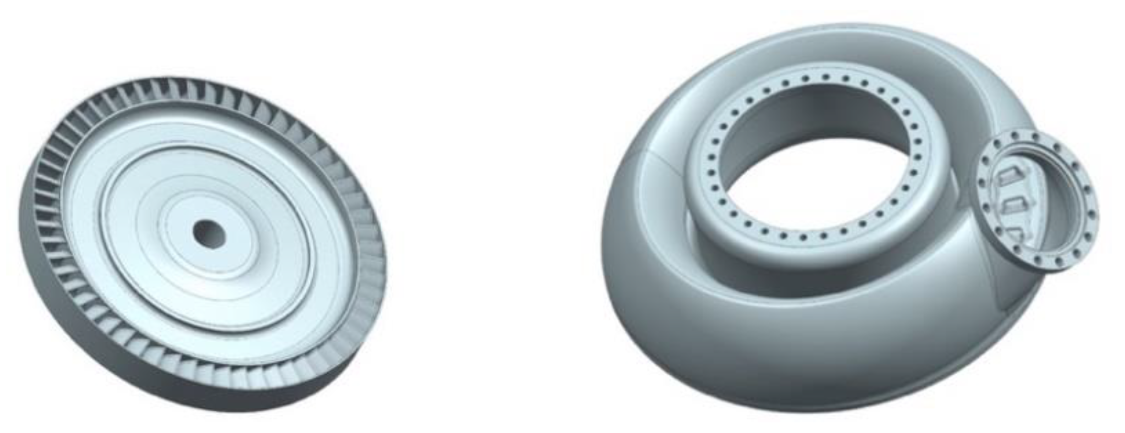
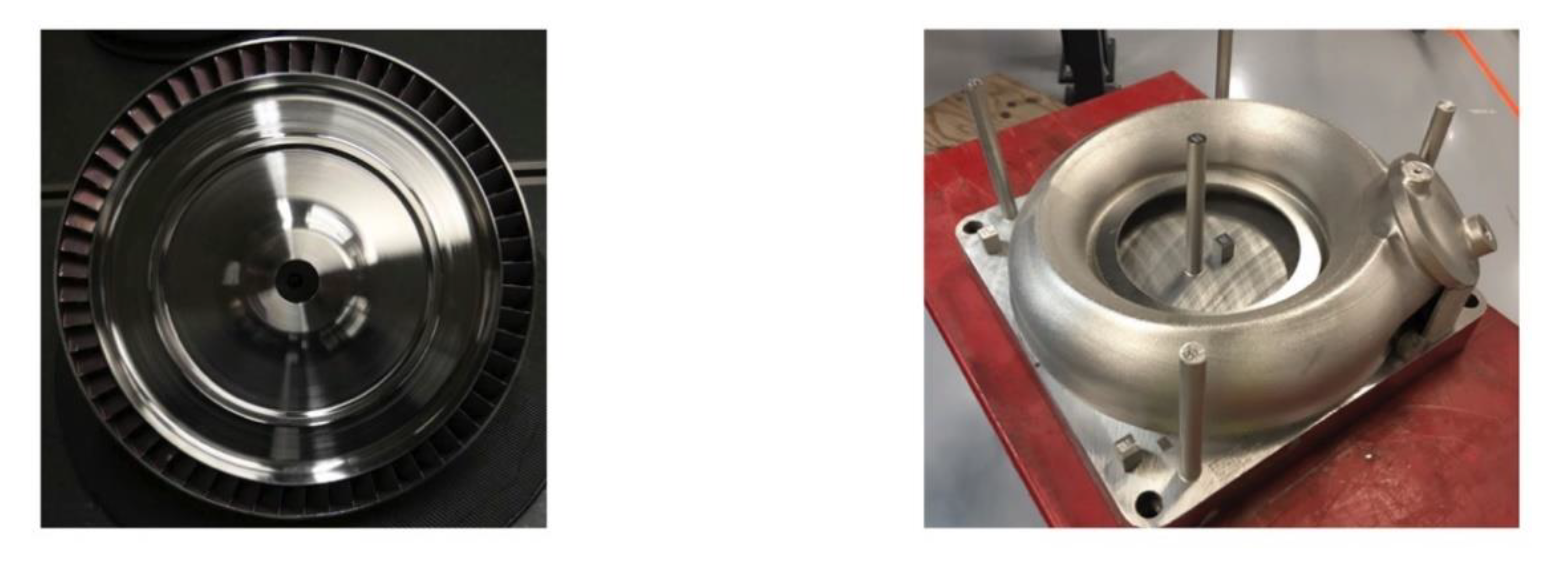
3.1. Case Study
3.1.1. Design Approach
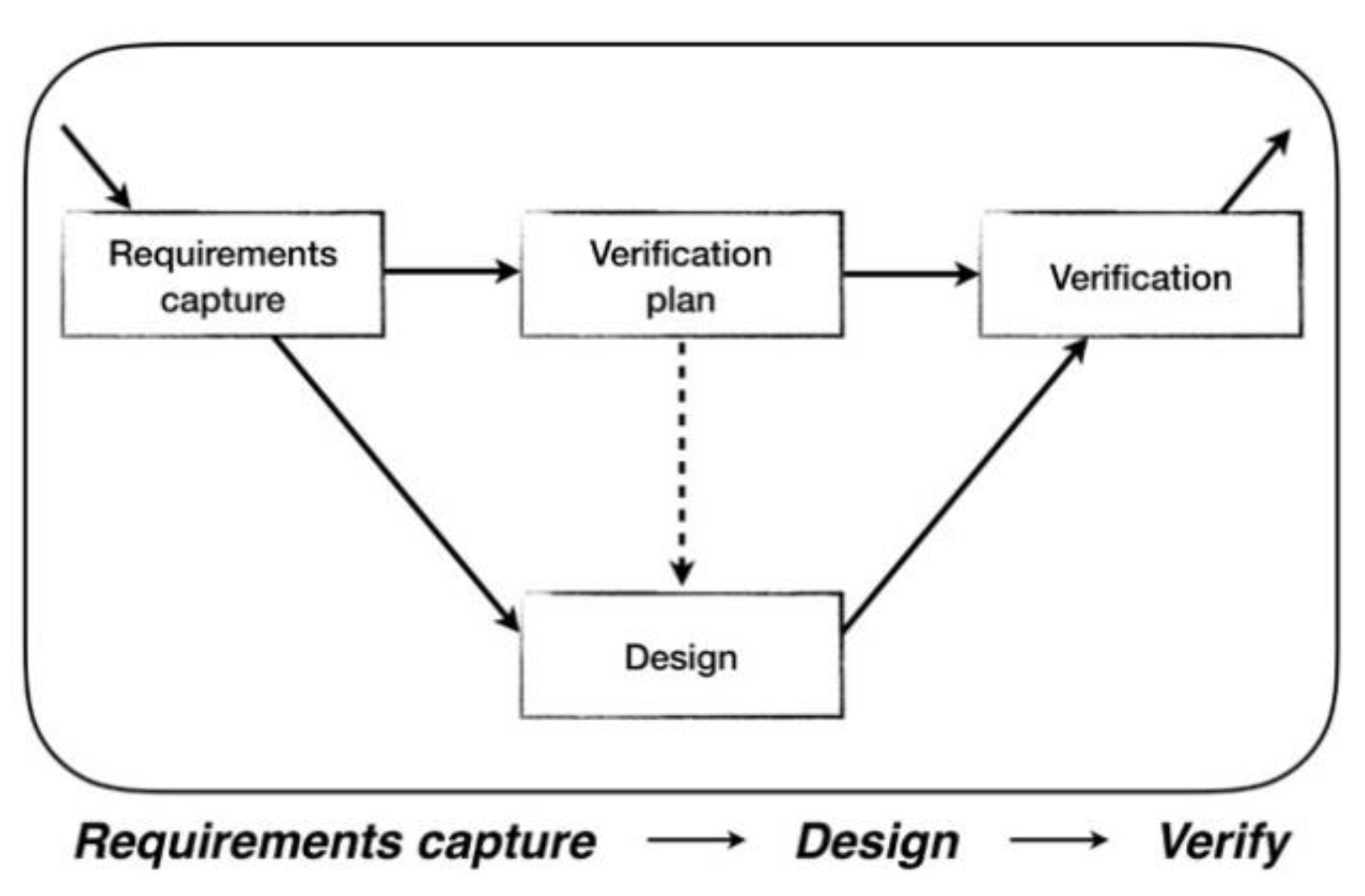
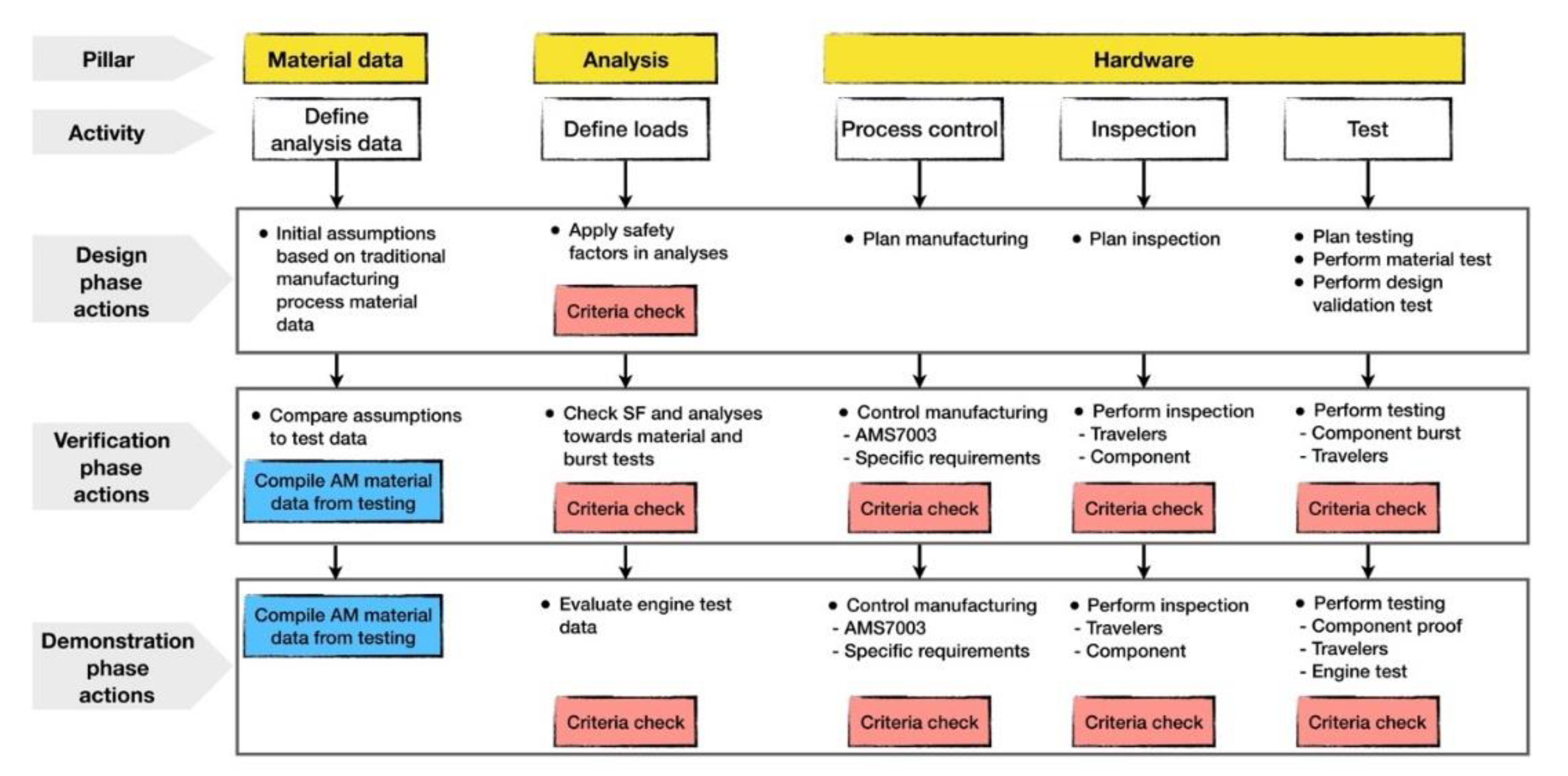
3.1.2. Verification Approach
- Use of relevant and conservative material data.
- Use of additional safety margins in analysis due to AM-related uncertainties.
- Assuring a stable AM process through process control and use of extensive inspection of each manufactured hardware, as well as destructive and non-destructive testing of components and travelers.
Material Data
Analysis
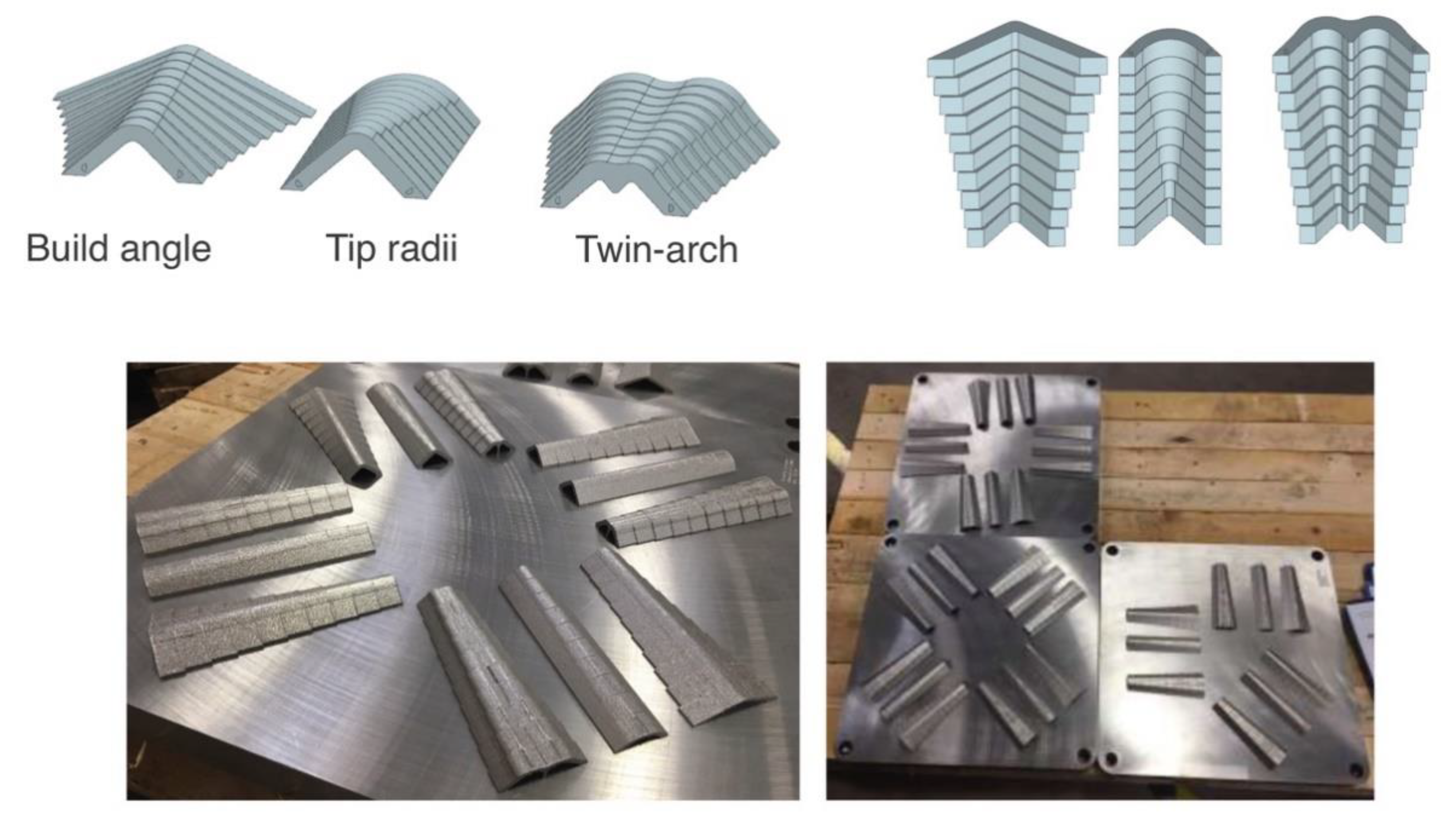
Hardware
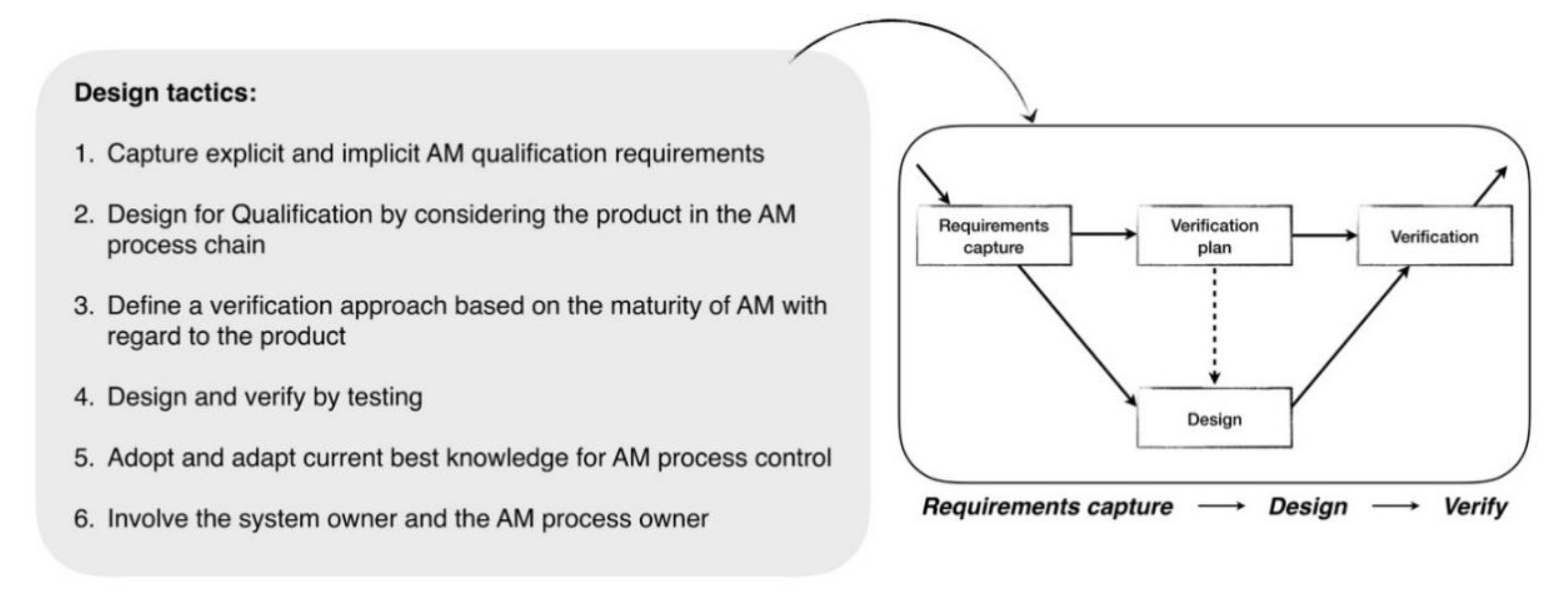
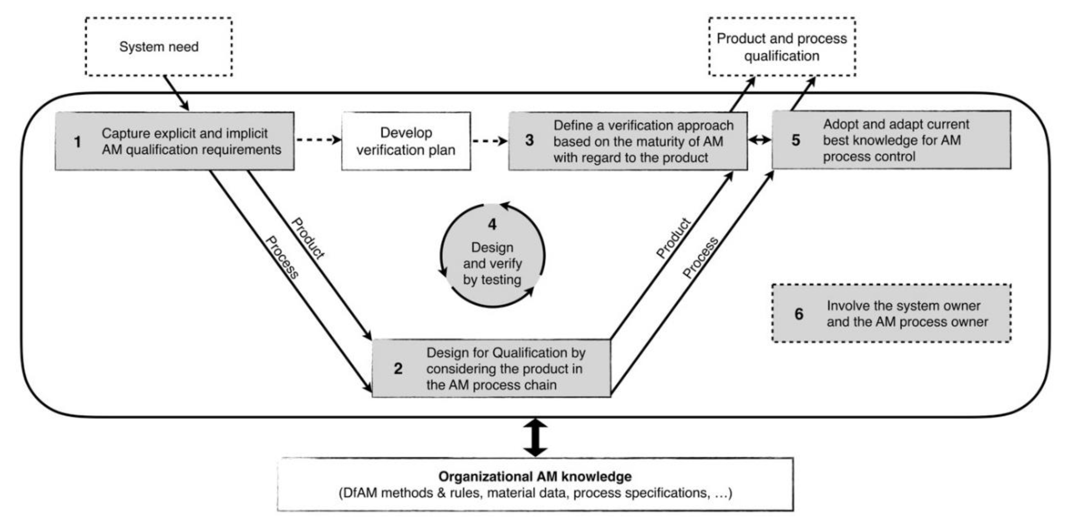
3.2. Proposal for Tactics to Design for Qualification
3.2.1. Tactic 1: Capture Explicit and Implicit AM Qualification Requirements
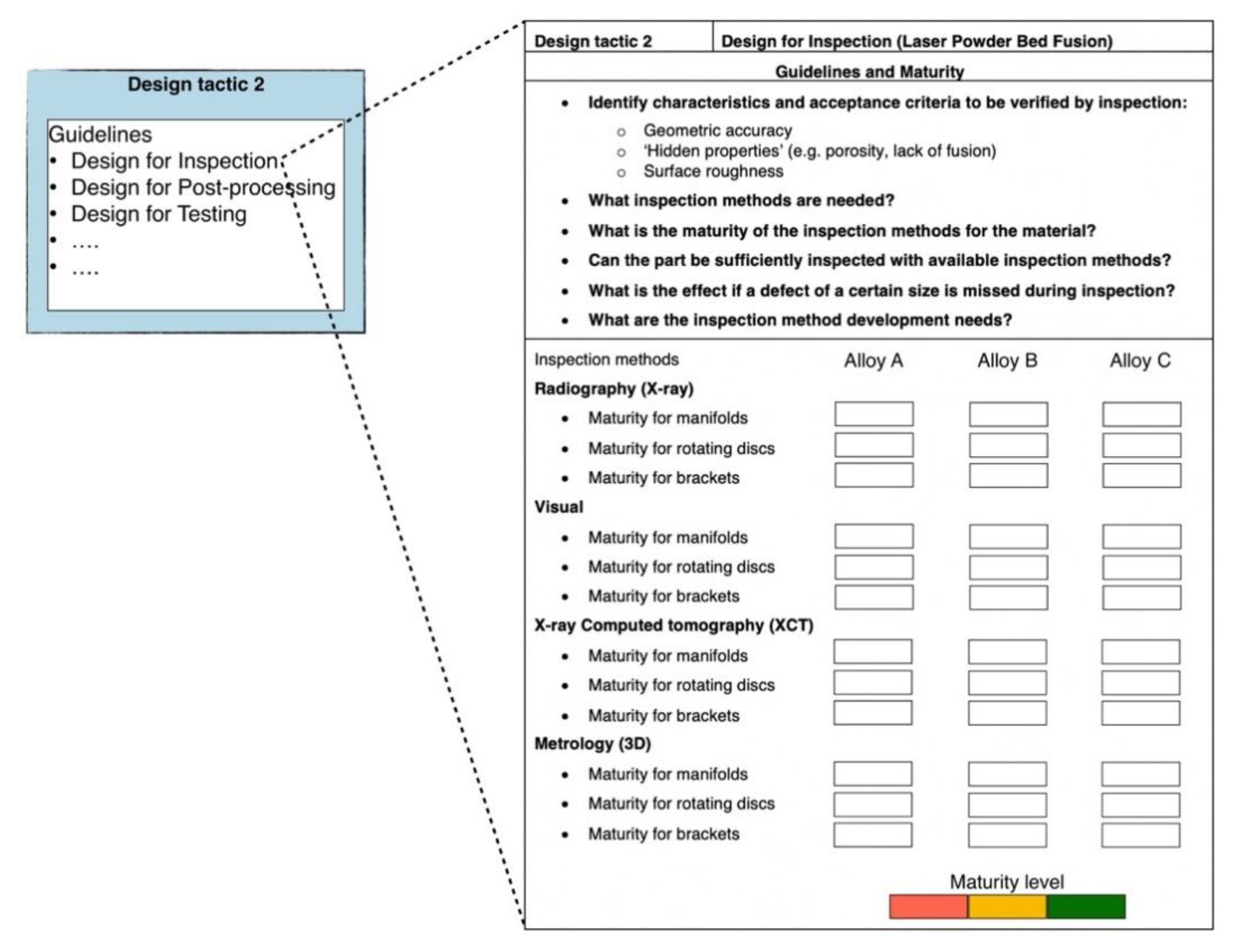
3.2.2. Tactic 2: Design for Qualification by Considering the Product in the AM Process Chain
3.2.3. Tactic 3: Define a Verification Approach based on the Maturity of AM with Regard to the Product
3.2.4. Tactic 4: Design and Verify by Testing
3.2.5. Tactic 5: Adopt and Adapt Current Best Knowledge for AM Process Control
3.2.6. Tactic 6: Involve the System Owner and the AM Process Owner
4. Discussion
4.1. Requirements Capture Phase (Tactic 1 and 6)
4.2. Design Phase (Tactic 2, 4 and 6)
4.3. Verification Phase (Tactic 3, 4 and 5)
4.4. Limitations and Future Work
5. Conclusions
Funding
Acknowledgments
Conflicts of Interest
References
- Dordlofva, C.; Brodin, S.; Andersson, C. Using Demonstrator Hardware to Develop a Future Qualification Logic for Additive Manufacturing Parts. In Proceedings of the 70th International Astronautical Congress (IAC), Washington, DC, USA, 21–25 October 2019. [Google Scholar]
- Frazier, W.E. Metal Additive Manufacturing: A Review. J. Mater. Eng. Perform. 2014, 23, 1917–1928. [Google Scholar] [CrossRef]
- Gorelik, M. Additive manufacturing in the context of structural integrity. Int. J. Fatigue 2017, 94, 168–177. [Google Scholar] [CrossRef]
- Brodin, S.; Fernström, T.; Jensen, F.; Andersson, C.; Dordlofva, C. Status Report Prometheus LPBF Turbine Program. In Proceedings of the 70th International Astronautical Congress (IAC), Washington, DC, USA, 21–25 October 2019. [Google Scholar]
- Guichard, D.; Soller, S.; Götz, A.; Beyer, S.; Tertre, A.D.; Bernard, P.; Schelhorn, L.; Kaufmann, V. Additive Manufacturing Opportunities in Combustion Devices for Liquid Rocket Engines. In Proceedings of the 6th Space Propulsion Conference, Seville, Spain, 14–18 May 2018. [Google Scholar]
- O’Brien, M.J. Development and qualification of additively manufactured parts for space. Opt. Eng. 2019, 58. [Google Scholar] [CrossRef]
- ESA. Prometheus to Power Future Launchers. Available online: https://www.esa.int/Our_Activities/Space_Transportation/Prometheus_to_power_future_launchers (accessed on 24 March 2019).
- Castro, J.; Sack, W.; Littles, J. Leveraging Additive Manufacturing for Affordable Commercial Launch Applications Enabled by the Aerojet Rocketdyne Ultra-Low-Cost Bantam Engine Family. In Proceedings of the International Astronautical Congress, IAC, Guadalajara, Mexico, 26 September 2016. [Google Scholar]
- Iannetti, A.; Girard, N.; Tchou-kien, D.; Bonhomme, C.; Ravier, N.; Edeline, E. Prometheus, a LOX/LCH4 Reusable Rocket Engine. In Proceedings of the 7th European Conference for Aeronautics and Space Sciences (EUCASS), Milan, Italy, 3–6 July 2017. [Google Scholar] [CrossRef]
- Thales. “Addictive” Manufacturing. Available online: https://www.thalesgroup.com/en/worldwide/space/news/addictive-manufacturing (accessed on 2 July 2019).
- Rawal, S.; Brantley, J.; Karabudak, N. Additive Manufacturing of Ti-6Al-4V alloy components for spacecraft applications. In Proceedings of the 6th International Conference on Recent Advances in Space Technologies (RAST), Istanbul, Turkey, 12–14 June 2013; pp. 5–11. [Google Scholar] [CrossRef]
- Orme, M.E.; Gschweitl, M.; Ferrari, M.; Madera, I.; Mouriaux, F. Designing for Additive Manufacturing: Lightweighting Through Topology Optimization Enables Lunar Spacecraft. J. Mech. Des. 2017, 139, 1–6. [Google Scholar] [CrossRef]
- RUAG. First 3D Printed Part will be Landing on the Moon Soon. Available online: https://www.ruag.com/en/news/ruag-space-first-3d-printed-part-will-be-landing-moon-soon (accessed on 2 July 2019).
- Wagner, S.M.; Walton, R.O. Additive manufacturing’s impact and future in the aviation industry. Prod. Plan. Control 2016, 27, 1124–1130. [Google Scholar] [CrossRef]
- Brandão, A.D.; Gerard, R.; Gumpinger, J.; Beretta, S.; Makaya, A.; Pambaguian, L.; Ghidini, T. Challenges in Additive Manufacturing of Space Parts: Powder Feedstock Cross-Contamination and Its Impact on End Products. Materials 2017, 10, 522. [Google Scholar] [CrossRef]
- Zhu, Z.; Pradel, P.; Bibb, R.; Moultrie, J. A Framework for Designing End Use Products for Direct Manufacturing Using Additive Manufacturing Technologies. In Proceedings of the 21st International Conference on Engineering Design (ICED17), Vancouver, BC, Canada, 21–25 August 2017; Volume 5, pp. 327–336. [Google Scholar]
- Seifi, M.; Salem, A.; Beuth, J.; Harrysson, O.; Lewandowski, J.J. Overview of Materials Qualification Needs for Metal Additive Manufacturing. JOM 2016, 68, 747–764. [Google Scholar] [CrossRef]
- ECSS. ECSS-Q-ST-30C Rev.1—Space Product Assurance—Dependability 2017. Available online: https://ecss.nl/standard/ecss-q-st-30c-rev-1-space-product-assurance-dependability-15-february-2017/ (accessed on 9 March 2020).
- Musgrave, G.E.; Larsen, A.M.; Sgobba, T. (Eds.) Safety Design for Space Systems, 1st ed.; Butterworth-Heinemann: Oxford, UK, 2009. [Google Scholar]
- Dordlofva, C.; Törlind, P. Qualification Challenges with Additive Manufacturing in Space Applications. In Proceedings of the 28th Annual International Solid Freeform Fabrication Symposium, Austin, TX, USA, 7–9 August 2017; pp. 2699–2712. [Google Scholar]
- Seifi, M.; Gorelik, M.; Waller, J.; Hrabe, N.; Shamsaei, N.; Daniewicz, S.; Lewandowski, J.J. Progress Towards Metal Additive Manufacturing Standardization to Support Qualification and Certification. JOM 2017, 69, 439–455. [Google Scholar] [CrossRef]
- Dordlofva, C.; Borgue, O.; Panarotto, M.; Isaksson, O. Drivers and Guidelines in Design for Qualification Using Additive Manufacturing in Space Applications. Proc. Des. Soc. Int. Conf. Eng. Des. 2019, 1, 729–738. [Google Scholar] [CrossRef]
- AMSC. Standardization Roadmap for Additive Manufacturing (Version 2.0). 2018. Available online: http://www.ansi.org/amsc (accessed on 9 March 2020).
- ECSS. ECSS-S-ST-00-01C—ECSS System—Glossary of Terms 2012. Available online: https://ecss.nl/standard/ecss-s-st-00-01c-glossary-of-terms-1-october-2012/ (accessed on 9 March 2020).
- Fortescue, P.; Swinerd, G.; Stark, J. (Eds.) Spacecraft Systems Engineering, 4th ed.; John Wiley & Sons: Chichester, UK, 2011. [Google Scholar]
- Monzón, M.D.; Ortega, Z.; Martínez, A.; Ortega, F. Standardization in additive manufacturing: Activities carried out by international organizations and projects. Int. J. Adv. Manuf. Technol. 2014, 76, 1111–1121. [Google Scholar] [CrossRef]
- Russell, R. NASA’s Plans for Development of a Standard for Additively Manufactured Components. J. Mater. Eng. Perform. 2019, 28, 1924–1928. [Google Scholar] [CrossRef]
- NASA Standard for Additively Manufactured Spaceflight Hardware by Laser Powder Bed Fusion in Metals (MSFC-STD-3716, Baseline) 2017; NASA: Washington, DC, USA, 2017.
- NASA Specification for Control and Qualification of Laser Powder Bed Fusion Metallurgical Processes (MSFC-SPEC-3717, Baseline) 2017; NASA: Washington, DC, USA, 2017.
- ECSS. ECSS-E-ST-32-01C Rev.1—Space Engineering—Fracture Control 2009. Available online: https://ecss.nl/standard/ecss-e-st-32-01c-rev-1-fracture-control/ (accessed on 9 March 2020).
- Thompson, A.; Maskery, I.; Leach, R.K. X-ray computed tomography for additive manufacturing: A review. Meas. Sci. Technol. 2016, 27, 072001. [Google Scholar] [CrossRef]
- Fitzgerald, E.; Everhart, W. The Effect of Location on the Structure and Mechanical Properties of Selective Laser Melted 316L Stainless Steel. In Proceedings of the 27th Annual International Solid Freeform Fabrication Symposium, Austin, TX, USA, 8–10 August 2016; pp. 574–583. [Google Scholar]
- Soller, S.; Barata, A.; Beyer, S.; Dahlhaus, A.; Guichard, D.; Humbert, E.; Kretschmer, J.; Zeiss, W. Selective Laser Melting (SLM) of Inconel 718 and Stainless Steel Injectors for Liquid Rocket Engines. In Proceedings of the Space Propulsion, Rome, Italy, 2–6 May 2016. [Google Scholar]
- Romano, S.; Brandão, A.; Gumpinger, J.; Gschweitl, M.; Beretta, S. Qualification of AM parts: Extreme value statistics applied to tomographic measurements. Mater. Des. 2017, 131, 32–48. [Google Scholar] [CrossRef]
- Taylor, R.M.; Manzo, J.; Flansburg, L. Certification Strategy for Additively Manufactured Structural Fittings. In Proceedings of the 27th Solid Freeform Fabrication Symposium, Austin, TX, USA, 8–10 August 2016; pp. 1985–2000. [Google Scholar]
- Kumke, M.; Watschke, H.; Vietor, T. A new methodological framework for design for additive manufacturing. Virtual Phys. Prototyp. 2016, 11, 3–19. [Google Scholar] [CrossRef]
- Yang, S.; Zhao, Y.F. Additive manufacturing-enabled design theory and methodology: A critical review. Int. J. Adv. Manuf. Technol. 2015, 80, 327–342. [Google Scholar] [CrossRef]
- Pradel, P.; Zhu, Z.; Bibb, R.; Moultrie, J. A framework for mapping design for additive manufacturing knowledge for industrial and product design. J. Eng. Des. 2018, 29, 291–326. [Google Scholar] [CrossRef]
- Laverne, F.; Segonds, F.; Anwer, N.; le Coq, M. Assembly Based Methods to Support Product Innovation in Design for Additive Manufacturing: An Exploratory Case Study. J. Mech. Des. 2015, 137, 121701. [Google Scholar] [CrossRef]
- Segonds, F. Design by Additive Manufacturing: An application in aeronautics and defence. Virtual Phys. Prototyp. 2018, 13, 237–245. [Google Scholar] [CrossRef]
- Kumke, M.; Watschke, H.; Hartogh, P.; Bavendiek, A.K.; Vietor, T. Methods and tools for identifying and leveraging additive manufacturing design potentials. Int. J. Interact. Des. Manuf. 2018, 12, 481–493. [Google Scholar] [CrossRef]
- Adam, G.A.O.; Zimmer, D. On design for additive manufacturing: Evaluating geometrical limitations. Rapid Prototyp. J. 2015, 21, 662–670. [Google Scholar] [CrossRef]
- Salmi, A.; Calignano, F.; Galati, M.; Atzeni, E. An integrated design methodology for components produced by laser powder bed fusion (L-PBF) process. Virtual Phys. Prototyp. 2018, 13, 191–202. [Google Scholar] [CrossRef]
- Leutenecker-Twelsiek, B.; Klahn, C.; Meboldt, M. Considering Part Orientation in Design for Additive Manufacturing. Procedia Cirp 2016, 50, 408–413. [Google Scholar] [CrossRef]
- Booth, J.W.; Alperovich, J.; Chawla, P.; Ma, J.; Reid, T.N.; Ramani, K. The design for additive manufacturing worksheet. J. Mech. Des. Trans. ASME 2017, 139, 1–9. [Google Scholar] [CrossRef]
- Rohde, J.; Jahnke, U.; Lindemann, C.; Kruse, A.; Koch, R. Standardised product development for technology integration of additive manufacturing. Virtual Phys. Prototyp. 2019, 14, 141–147. [Google Scholar] [CrossRef]
- CMH-17 Composite Materials Handbook-17—Volume 3; SAE International: Warrendale, PA, USA, 2012; ISBN 9780768078312.
- Portolés, L.; Jordá, O.; Jordá, L.; Uriondo, A.; Esperon-Miguez, M.; Perinpanayagam, S. A qualification procedure to manufacture and repair aerospace parts with electron beam melting. J. Manuf. Syst. 2016, 41, 65–75. [Google Scholar] [CrossRef]
- Holt, R.; Barnes, C. Towards an integrated approach to “Design for X”: An agenda for decision-based DFX research. Res. Eng. Des. 2010, 21, 123–136. [Google Scholar] [CrossRef]
- Bralla, J.G. Design for Excellence, 1st ed.; McGraw-Hill/Knovel: New York, NY, USA, 1996; ISBN 0-07-007138-1. [Google Scholar]
- Huang, G.Q. (Ed.) Design for X: Concurrent Engineering Imperatives, 1st ed.; Springer Science+Business Media: Dordrecht, The Netherland, 1996. [Google Scholar] [CrossRef]
- Alexander, K.; Clarkson, P.J. Good design practice for medical devices and equipment, Part II: Design for validation. J. Med Eng. Technol. 2000, 24, 53–62. [Google Scholar] [CrossRef] [PubMed]
- Alexander, K.; Clarkson, P.J. A validation model for the medical devices industry. J. Eng. Des. 2002, 13, 197–204. [Google Scholar] [CrossRef]
- Ulrich, K.T.; Eppinger, S.D. Product Design and Development, 5th ed.; McGraw-Hill Education: Boston, MA, USA, 2012; ISBN 0071137424. [Google Scholar]
- Coghlan, D.; Brannick, T. Doing Action Research in Your Own Organization, 4th ed.; Sage Publications: London, UK, 2014; ISBN 978-1-4462-7256-5. [Google Scholar]
- Svensson, L.; Brulin, G.; Ellström, P.-E. Interactive research and ongoing evaluation as joint learning processes. In Sustainable Development in Organizations: Studies on Innovative Practices; Elg, M., Ellström, P.-E., Klofsten, M., Tillmar, M., Eds.; Edward Elgar Publishing Limited: Cheltenham, UK, 2015; pp. 346–361. ISBN 978-1-78471-689-9. [Google Scholar] [CrossRef]
- Eisenhardt, K.M.; Graebner, M.E. Theory building from cases: Opportunities and challenges. Acad. Manag. J. 2007, 50, 25–32. [Google Scholar] [CrossRef]
- Yin, R.K. Case Study Research: Design and Methods, 5th ed.; Sage Publications: Thousand Oaks, CA, USA, 2014; ISBN 978-1-4522-4256-9. [Google Scholar]
- Dordlofva, C.; Törlind, P. Evaluating Design Uncertainties in Additive Manufacturing using Design Artefacts: Examples from Space Industry. Desing Sci. 2020; (under review). [Google Scholar]
- Bryman, A.; Bell, E. Business Research Methods, 4th ed.; Oxford University Press: Oxford, UK, 2015; ISBN 978-0-19-966864-9. [Google Scholar]
- Miles, M.B.; Huberman, M.A.; Saldaña, J. Qualitative Data Analysis: A Methods Sourcebook, 3rd ed.; Sage Publications: Thousand Oaks, CA, USA, 2014; ISBN 978-1-4522-5787-7. [Google Scholar]
- SAE International. Laser Powder Bed Fusion Process—AMS7003 2018. Available online: https://www.sae.org/standards/content/ams7003/ (accessed on 9 March 2020).
- Kennedy, B.M.; Sobek, D.K.; Kennedy, M.N. Reducing Rework by Applying Set-Based Practices Early in the Systems Engineering Process. Syst. Eng. 2014, 17, 278–296. [Google Scholar] [CrossRef]
- Forsberg, K.; Mooz, H. The Relationship of System Engineering to the Project Cycle. In Proceedings of the National Council on Systems Engineering (NCOSE) Conference, Chattanooga, TN, USA, 20–23 October 1991; pp. 1–12. [Google Scholar] [CrossRef]
- Peralta, A.D.; Enright, M.; Megahed, M.; Gong, J.; Roybal, M.; Craig, J. Towards rapid qualification of powder-bed laser additively manufactured parts. Integr. Mater. Manuf. Innov. 2016, 5, 154–176. [Google Scholar] [CrossRef]
- Kolb, T.; Mahr, A.; Huber, F.; Tremel, J.; Schmidt, M. Qualification of channels produced by laser powder bed fusion: Analysis of cleaning methods, flow rate and melt pool monitoring data. Addit. Manuf. 2019, 25, 430–436. [Google Scholar] [CrossRef]
- Wynn, D.C.; Clarkson, P.J. Process models in design and development. Res. Eng. Des. 2018, 29, 161–202. [Google Scholar] [CrossRef]
- Boothroyd, G. Product design for manufacture and assembly. Comput. -Aided Des. 1994, 26, 505–520. [Google Scholar] [CrossRef]


| What | Quantity | Comment |
|---|---|---|
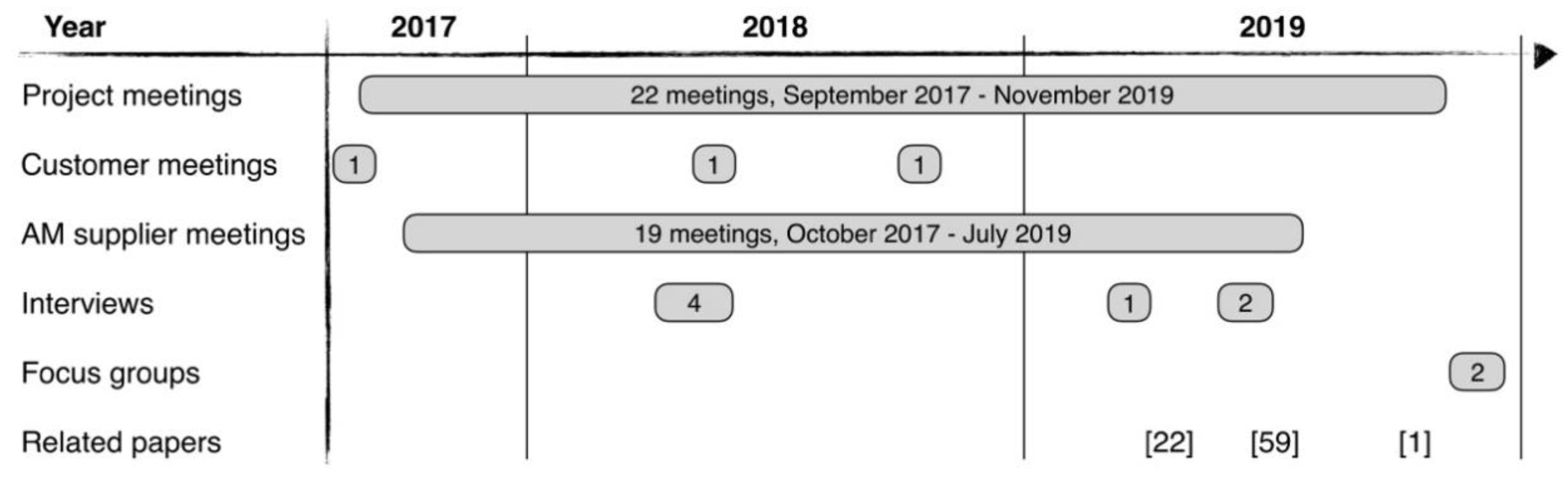
| Meeting notes Project meetings Customer meetings AM supplier meetings | 22 meetings 3 meetings 19 meetings | 27 months (September 2017 to November 2019) General project meetings, design reviews, AM verification meetings Design reviews and AM verification meetings Scheduled ‘weekly’ meetings |
| Internal documents | 1 document | Summarizing documentation for internal critical design review (CDR). |
| Un-structured interviews At the company (two sites) AM supplier | 6 respondents 1 respondent | Respondents were not directly involved in the development project, providing ‘external’ views on product development with AM. AM supplier used by the development project. |
| Focus groups | 2 groups | Group 1: 6 participants (design, material and process engineers) Group 2: 2 participants (engineering organization managers) |
| Process Control | Inspection | Testing |
|---|---|---|
|
|
|
© 2020 by the author. Licensee MDPI, Basel, Switzerland. This article is an open access article distributed under the terms and conditions of the Creative Commons Attribution (CC BY) license (http://creativecommons.org/licenses/by/4.0/).
Share and Cite
Dordlofva, C. A Design for Qualification Framework for the Development of Additive Manufacturing Components—A Case Study from the Space Industry. Aerospace 2020, 7, 25. https://doi.org/10.3390/aerospace7030025
Dordlofva C. A Design for Qualification Framework for the Development of Additive Manufacturing Components—A Case Study from the Space Industry. Aerospace. 2020; 7(3):25. https://doi.org/10.3390/aerospace7030025
Chicago/Turabian StyleDordlofva, Christo. 2020. "A Design for Qualification Framework for the Development of Additive Manufacturing Components—A Case Study from the Space Industry" Aerospace 7, no. 3: 25. https://doi.org/10.3390/aerospace7030025
APA StyleDordlofva, C. (2020). A Design for Qualification Framework for the Development of Additive Manufacturing Components—A Case Study from the Space Industry. Aerospace, 7(3), 25. https://doi.org/10.3390/aerospace7030025