Article

Design and Testing of a Paraffin-Based 1000 N HRE Breadboard

by
Francesco Battista
1,*,†,
Daniele Cardillo
1,†,
Manrico Fragiacomo
1,
Giuseppe Daniele Di Martino
2,
Stefano Mungiguerra
2 and
Raffaele Savino
2
1
CIRA, Italian Aerospace Research Centre, 81043 Capua, Italy
2
Department of Industrial Engineering—Aerospace Division, University of Naples “Federico II”, Piazzale Tecchio, 80, 80125 Naples, Italy
*
Author to whom correspondence should be addressed.
These authors contributed equally to this work.
Aerospace 2019, 6(8), 89; https://doi.org/10.3390/aerospace6080089
Submission received: 17 June 2019 / Revised: 3 August 2019 / Accepted: 4 August 2019 / Published: 12 August 2019

Abstract

:
The paper presents some relevant achievements in hybrid rocket propulsion carried out by the Italian Aerospace Research Centre. On the basis of the experimental results obtained on a 200 N thrust class engine, a 1000 N class breadboard, fed with gaseous oxygen coupled with a paraffin-based fuel grain, was designed and experimentally tested in different conditions. The breadboard exhibited a stable combustion in all the firing test conditions; the testing campaign allowed the acquisition of different experimental data, as pre and post-combustion chamber pressure, throat material temperature, pre-combustion chamber temperature. The new breadboard was characterized by higher measured regression rate values with respect to corresponding data obtained with the smaller scale one, highlighting that the oxidizer mass flux is not the only operating quantity affecting the fuel consumption behavior, which could be also influenced by scale parameters, such as the grain port diameter, and other operating conditions, such as the mixture ratio.

1. Introduction

Numerous interesting features give to hybrid rocket propulsion technology potential advantage over both solid and liquid propulsion systems, such as safety, low development costs, minimal environmental impact, re-ignition and throttling capabilities. A thorough explanation of these aspects can be found in the work by Altman and Holzman [1].
Nevertheless, to effectively demonstrate its advantages over the actual consolidated technologies, the TRL of HRE systems should be further increased for a carefully selected class of missions, as indicated by Karabeyoglu [2]. In fact, the hybrid engine development has not still achieved the same level of maturity as solid and liquid traditional systems.
Some disadvantages of the HRE technology include the low fuel regression rate, the combustion efficiency and the oxidizer to fuel mixture ratio shift.
In the last years, paraffin-based fuels gained much attention, due to higher regression rates with respect to classical polymeric fuels [3]. Specifically, in addition to the classical fuel regression rate due to evaporation, in this class of polymers there is a further contribution to regression rate due to entrainment. The formation of a low-viscosity unstable melt layer, on the burning surface, leads to fuel liquid droplets entrainment into the main gas stream, which significantly increases the solid regression rate.
Detailed studies have been presented by Karabeyoglu [4,5], where it is demonstrated that the fuel composition and its thermo-mechanical properties strongly affect the liquid layer instability and, therefore, the fuel regression rate.
In this scenario, the present research was mainly focused on the investigation of the fuel characteristics, in order to ensure high performance in terms of regression rate but maintaining good mechanical properties. In a previous authors’ work, results of an experimental test campaign, performed at subscale level on a 200 N breadboard, demonstrated very good performances and mechanical properties of the analyzed paraffin-wax formulation [6].
Based on these results, the main objective of the present work is the scale-up of the fuel grain, adopting the same fuel formulation, and the design of a new breadboard, moving towards the 1000 N thrust class. A new experimental test campaign was carried out on the 1000 N breadboard, allowing for the investigation of the paraffin-based fuel blend behavior on a larger scale. In particular, with respect to subscale experiments, the oxidizer to fuel mixture ratio range was extended. Numerous data were acquired, including chamber pressure, thrust, temperature of the flow in the pre-chamber and temperature inside the graphite nozzle material. The latter parameter allows for the estimation of the convective heat transfer coefficient in the nozzle region, which is strictly linked to the graphite nozzle thermo-chemical erosion. This is an extremely important parameter to be evaluated, since the throat area enlargement directly affects the motor performances [7].
The results of the experimental test campaign show that hybrid rocket engine can operate, with good efficiency and stability, in a wide range of operating conditions, confirming some of the advantages over both solid and liquid technologies often mentioned in the relevant literature [1,2,8,9].

2. Methodology and Design

2.1. Design Logic

The procedure, adopted for the design of the 1000 N hybrid breadboard, is based on an iterative process in time, which is schematically represented in Figure 1, and was implemented in a relatively simple and fast design tool (named HDC code). The HDC code, once selected the propellants and given the required engine performance in terms of average thrust (T) and the minimum total impulse (Itot), provides the design oxidizer mass flow rate and the total burning time. After that, for the chosen propellants, the regression rate law can be selected (see Section 2.2), which is integrated in time for the fuel grain sizing; in particular, fuel grain internal diameter and length are optimized to ensure a thrust profile with maximum deviation of 10%, on thrust, during firing.
Combustion equilibrium data, obtained from the RPA (Rocket Propulsion Analysis) lite software [10], are used. Combustion properties, derived from RPA, are interpolated as a function of chamber pressure and mixture ratio.
T c = f ( M R , p c ) ,     M W = f ( M R , p c ) ,     γ ( M R , p c )
From these quantities, rocket performance at each time step are calculated considering a combustion efficiency and nozzle efficiency according to [11].
The tool gives as output the baseline design of the injection system (given the oxidizer composition and its physical state), the case thickness, the throat regression, the pre and post-combustion chamber layout, providing the preliminary design of the configuration.
The demonstrator was preliminarily designed, with the exposed procedure that provides the main thruster geometrical characteristics and performances. The nominal target data for the design of the breadboard, in terms of minimum total impulse and nominal thrust, are 104 N·s and 1000 N, respectively. In order to take into account uncertainties in regression rate law, a total impulse of 2 × 10⁴ N·s (>104 N·s) was considered as input data for the HDC code. This is to avoid total consumption of the fuel grain before the end of the firing, which could lead to expose the breadboard case to high thermal loads. The regression rate selected for design will be analyzed later, the dependence of regression rate on the axial coordinate has been preliminary taken into account according to [12]. The results of the preliminary design process are reported in Figure 2a (profiles of pressure and thrust over time) and Figure 2b (thruster configuration and expected grain recession), the expected mean fuel grain regression rate is 1.9 mm/s. It is worth to notice that, in the first 8 s, thrust (Figure 2a) remains almost constant; this because the change in the thrust coefficient, deriving from the thermodynamic properties variation with the fast varying oxidizer to fuel ratio, compensates the pressure decrease. The port diameter has been optimized in order to have the optimum mean thrust (considering 20 s of firing time) once fixed the grain length. Post and pre-chamber play an important role in hybrid rocket engine combustion efficiency, they have been dimensioned according to the principles reported in [13]. The injectors diameters have been selected according to the criteria reported in [14] for gaseous injectors considering an oxygen nominal mass flow rate of 0.260 kg/s. Detailed design analyses on this breadboard configuration can be found in [15].

2.2. Fuel Regression Rate Formulation

The fuel regression rate law, considered in the present work, is referred to paraffin-based fuel grains burning with gaseous oxygen. The fuel formulation is a blend of paraffin waxes, which mainly include microcrystalline paraffin commercialized by SASOL® (labelled with the trade code 0907—see Table 1). Previous investigations by CIRA [16] showed high fracture toughness and workability of the SASOL 0907. Other paraffin-waxes and additives are included in the adopted formulation to enhance both mechanical characteristics and performances. They include a refined low melting point (58–62 °C) paraffin, relatively high melting point microcrystalline wax (about 100 °C) and stearic acid. A small amount of a blackening additive was added to the melted wax, to increase the thermal radiation absorption at the fuel surface improving the regression rate [5,17].
The formulation was tested on a 200 N subscale breadboard, in different operating conditions, in order to evaluate the regression rate and the mechanical behavior [6]. Several tests were performed up to 60 g/s oxygen mass-flow rate, corresponding to 1.9 MPa for chamber pressure and about 200 N for thrust. Since the employed breadboard was optimized for operation with classical polymeric fuels (in the range of typical obtainable mass flow rates and pressures), tests with paraffin-based fuels were characterized by relatively low mixture ratios, up to 1.2. Results in terms of fuel regression rate against oxidizer mass-flux are reported in Figure 3 and compared with well-known literature results.
The paraffin-based fuel showed good mechanical properties and performances in terms of regression rate. The following correlation of the fuel regression rate as a function of the oxidizer mass flux was determined, based on the data acquired during the testing campaign.
r ˙ ¯ = a G ¯ o x n a = 0.071 ; n = 0.795 ; ( R 2 = 0.922 )
where the regression rate is expressed in mm/s and mass flux in kg/m2-s. Due to these results, this paraffin formulation was adopted for scaling-up the propellant grain to a higher thrust class breadboard (1000 N). In order to design the new test article, the correlation exposed in Equation (2) has been used.

3. Breadboard Architecture and Experimental Setup

3.1. Breadboard Description

The 1000 N breadboard completely assembled is depicted in Figure 4a, while details on the configuration are shown in Figure 4b.
The breadboard injection system is very simple and it is based on a showerhead architecture. The system is characterized by seven injectors (one on the breadboard axis see Figure 4b), of constant diameter, which ensure a more uniform axial flow at grain port inlet with respect to a single injector element with the same area. The injector plate is designed such that it can be easily replaced for testing other injector configurations. The external shell of the breadboard is made of stainless steel and contains the pre-chamber, the propellant grain, post combustion chamber and nozzle. The pre-chamber has a thermal protection system based on graphite and hosts a pressure transducer. Nozzle pre and post combustion chamber are protected by graphite; the post combustion chamber hosts a further pressure transducer. An embedded thermo-couple is located in proximity of the nozzle throat in order to monitor temperature of the zone, as shown in Figure 4. The ignition of the breadboard is assured by a spark plug located in the pre-chamber that ignites a mixture of oxygen and methane injected in the pre-chamber.

3.2. Test Rig Description and Test Setup

The test facility is a versatile experimental setup primarily designed for firing hybrid rocket engines of several sizes [6].
The piping and instrumentation schematic of the test rig is shown in Figure 5. Gaseous oxygen is supplied by a reservoir consisting of eight cylinders, while pressure regulators set the operating pressure along the breadboard feed line. Oxygen mass flow rate is evaluated through gas temperature and pressure measurements upstream of the throat of a chocked Venturi tube. The Venturi can be dismounted and replaced depending on the requested oxidizer mass-flow rate. For testing the 1000 N breadboard a 5 mm throat Venturi tube was adopted in order to guarantee the flow rate requested.
Nitrogen is purged into the chamber for the burn out and in case of an emergency shutdown.
Figure 6 shows the 1000 N breadboard integrated on the test bench. First, a leakage test was performed, using pressurized nitrogen at 0.8 MPa for five minutes, in order to verify the absence of any leak from internal interfaces.
Firing tests have been conducted with an incremental logic, being the hardware a new design, in order to evaluate the behavior of the breadboard from lower pressure/duration to higher ones.
The operating conditions of each test are reported in Table 2.
According to the incremental logic, the first test L1 was conducted with about the 50% oxidizer mass-flow rate for a shorter time (6 s) with respect to nominal one. In the second L2 test both oxidizer mass-flow rate and time were increased. In the L3 test the nominal firing time was further increased. Firing test L4 was made to demonstrate throttling capabilities of the breadboard. Test L5 was finally performed with the nominal oxidizer mass-flow rate.
The following telemetry set-up was adopted (see also Figure 4b):
  • Two Setra C206 pressure transducers, specifically in pre- and post-chamber, which can measure pressures up to 70 bar with an accuracy of ±0.1 bar and an acquisition frequency of 2.5 kHz;
  • A thermocouple (type K) in the breadboard pre-chamber directly in contact with the hot flow;
  • An embedded thermocouple (type K) in proximity of the nozzle throat (see Figure 7);
  • Four load cells for thrust measurement, with an overall accuracy of ±1.5 N.
Moreover, the oxidizer temperature and mass-flow rate were acquired, for all the firing tests.

4. Experimental Test Campaign: Results and Discussion

In this section the experimental results of the test campaign are presented and discussed.

4.1. Test Execution and Hardware Inspection

All the planned tests were successfully performed. No damage in any parts of the breadboard was detected. The experimental oxidizer mass-flow rates were in line with the test plan reported in Table 2, with deviations between nominal and experimental measured values below 10%.
Figure 8 shows pictures of the breadboard and the exhaust during firing test L1 (a) and firing test L3 (b). A remarkable difference stands out in both flame shape and brightness, due to different test conditions. In particular, in the higher oxidizer mass-flow rate condition of test L3, both exhaust velocity and flame temperature were higher, as will be later discussed.
The paraffin-wax grain, used before burning, is shown in Figure 9a, while Figure 9b shows the grain after firing test L3. A uniform consumption of the solid fuel grain was observed in radial direction, while axially there was a slightly higher regression at grain exit.
The weight of each propellant grain was measured after the firing tests for estimating the respective time-averaged fuel mass-flow rate and the corresponding time-averaged mixture ratio. Moreover, the mass loss method has been employed to estimate the space-averaged final port diameters, allowing computing the time-space averaged oxidizer mass-fluxes and fuel regression rates. For a detailed description of the data reduction technique refer to [6]. Propellant grains used for Test L4 and Test L5 reported an anomalous consumption in the inlet port diameter that shows a slightly larger diameter with respect to the medium one. Probably this is due to some delay experienced in the ignition sequence causing an initial overheating of the propellant. In any case no significant deviation in terms of thrust and pressure have been recorded during tests. No ablation occurred in the graphite nozzle, since the throat diameter remained unchanged during all the test campaign.

4.2. Experimental Regression Rate Considerations

The main measured quantities, for the different firing tests, are summarized in Table 3.
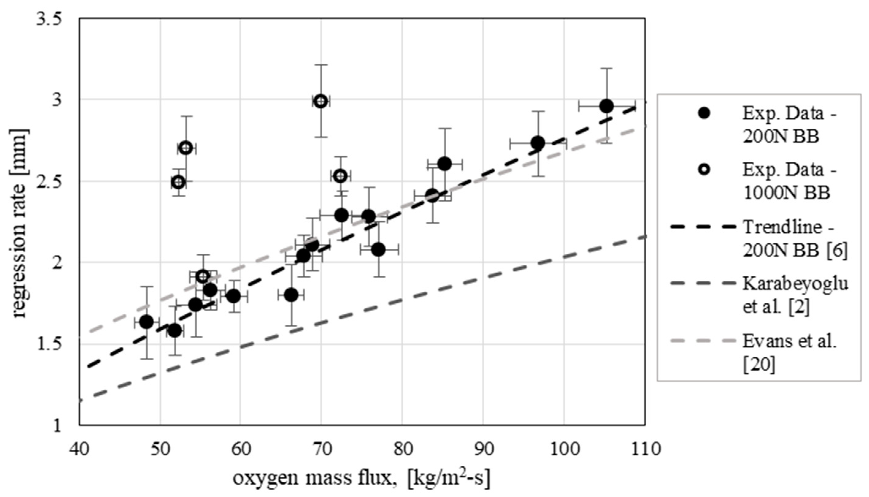
The experimental data point in terms of fuel regression rate as function of the oxidizer mass flux are reported in Figure 10 along with the data point measured on the subscale 200 N-class breadboard. Also, trends from relevant literature are reported for comparison. It is quite evident that, although the fuel grain formulation was the same, the regression rates experienced with the 1000 N breadboard, which range between about 1.9 mm/s (test L1) and 3 mm/s (test L5), are significantly higher with respect to the values obtained with the subscale breadboard at equal oxidizer mass flux. In fact, Table 4 reports the relative deviations between the expected values of the regression rate on the basis of the regression rate law as function of the oxidizer mass flux only (Equation (2)) and the corresponding measured data, which range between around 10% and 40% in module.
The above discussed results show that, while Equation (2) represents a sufficiently good fit of experimental data obtained with the 200 N breadboard, it leads to a non-negligible underestimation of the regression rate in the case of the larger scale engine. Consequently, in the scale-up of hybrid rockets it should be taken into account that the oxidizer mass flux is not the only quantity affecting the fuel regression rate. This is also confirmed by the fact that the experimental data for the 1000 N breadboard themselves do not show a clear trend of regression rate with oxygen mass flux. Therefore, other significant operating parameters must play a significant role, which should be properly investigated and assessed. In particular, the possible effect of two main parameters, i.e., the grain port diameter and the mixture ratio, on the fuel consumption behavior is discussed in the following and will be the subject of the future experimental investigations.
Recalling the main idea of previous authors’ work [6], the grain port diameter is a first quantity which could have an effect on the regression rate, as a consequence of the oxidizer injection flow pattern. In the case of axially injected oxidizer, a flow recirculation is created in the entrance region of the grain port where the oxidizer jet spreads up to the impingement point on the grain surface, enhancing the heat transfer to the wall. The extension of the vortex increases with the port diameter and, therefore, macroscopic result is that the fuel regression rate could be influenced by the port diameter other than by the mass flux [18]. For this reason, in Ref. [6] a correlation of the fuel regression rate with the oxidizer mass flux and the time-space averaged port diameter has been obtained which is expressed by
r ˙ ¯ = a G ¯ o x n D ¯ m a = 0.029 ; n = 0.697 ; m = 0.398 ( R 2 = 0.95 )
where the regression rate is expressed in mm/s, mass flux in kg/m2s and the port diameter is in mm.
Although it should be taken into account that the different injector and pre-chamber design limit the application of the above described correlation, the law of Equation (3) has been applied to calculate new values of the expected fuel regression rate and the results are reported in Table 5.
Although the deviations are reduced in almost all cases with respect to the basic formulation, the errors are still relatively high, so it can be concluded that combustion chamber conditions (i.e., MR, pc) directly affect the regression rate. In particular, as reported in [
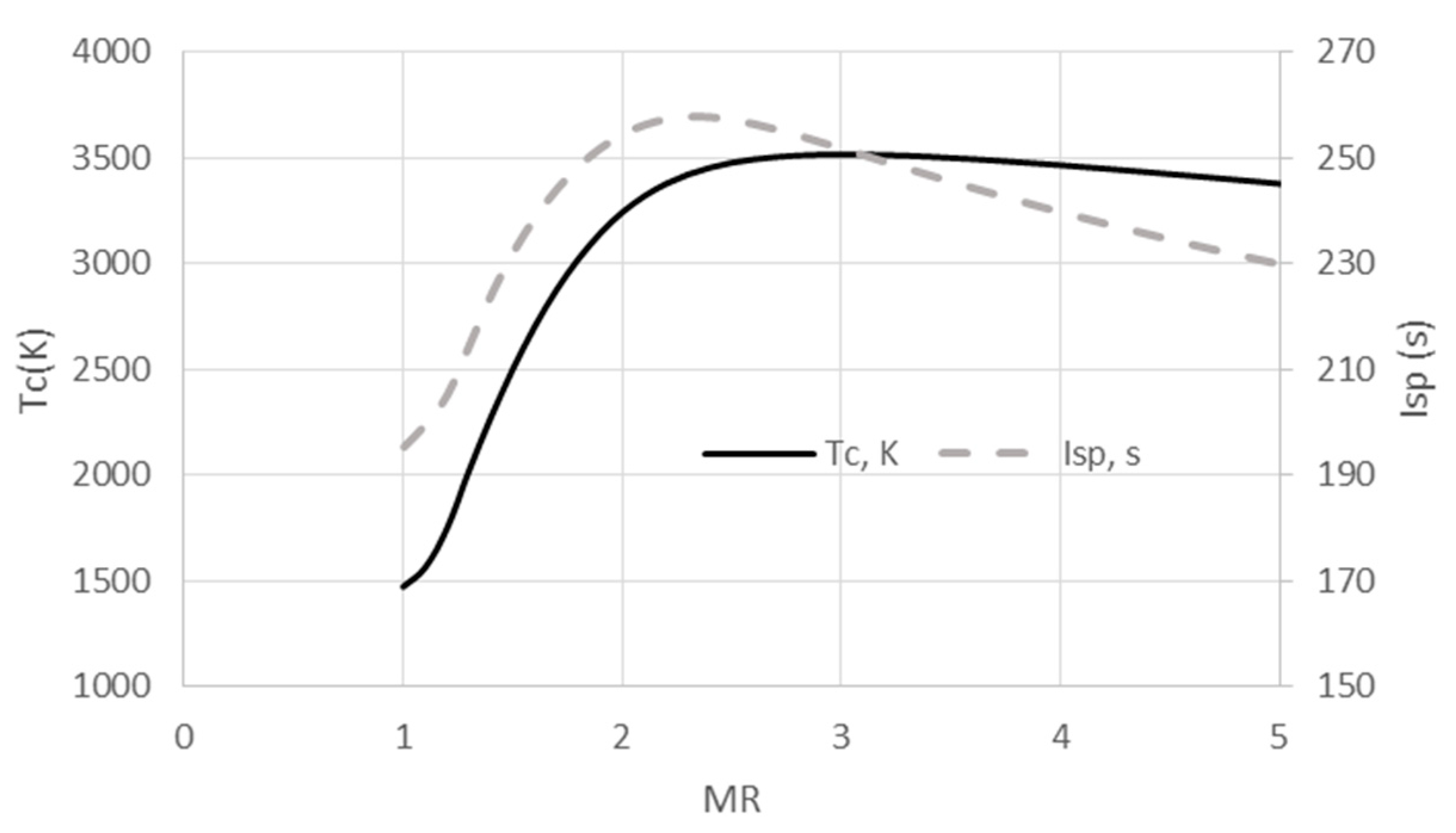
2], the regression rate could be significantly affected by the oxidizer-to-fuel ratio. In fact, from Figure 11, which shows the adiabatic flame temperature variation with mixture ratio at fixed chamber pressure ( 2 × 10 6   Pa ), it can be observed that in the mixture ratio range between 1 and 2 a strong temperature increase of the flame is expected. The temperature increase determines both increase of the heat transfer to the gas-liquid interface and variation of the gas properties, which in turn affect both the vaporization and the entrainment contributions to the fuel regression rate.
In particular, the vaporization contribution is given by the classical hybrid theory, which describes the regression rate of hybrid fuels in the absence of entrainment. The widely accepted formula due to Marxman et al. [19] shows the dependence of the vaporization regression rate with the gas properties (the gas viscosity in particular) and the radiative to convective heat transfer ratio.
r ˙ c l = C f , r e f ( 2 μ g L ) 0.2 C B 1 ( 1 + Q ˙ r Q ˙ c ) ( B ρ s ) G 0.8
where C f , r e f is the reference shear stress (generally assumed equal to 0.03) and C B 1 is a corrective factor of the surface friction [5]. It is evident that, once chosen the fuel propellant and fixed the oxidizer mass flux, the evaporation regression rate increases with the flame temperature due to both increase of gas viscosity and radiative to convective heat transfer ratio.
The entrainment contributions, on the two different breadboards, is more complex to define and requires deeper investigations. However, this mechanism is meanly related to the fuel properties, which remain unchanged. According to [5], the general empirical expression for the entrainment rate, in terms of the relevant properties of the hybrid breadboard, is
r ˙ e ( C f P d ) α h β σ γ μ δ
where α is approximately 1.5, β is approximately 2 and γ and δ are approximately 1. P d is the dynamic pressure of the gas flow in the port and C f has the same formulation of Equation (4), therefore depending on μ g 0.2 . Once the mass flux through the port is fixed, a higher flame temperature leads to an increase of both skin friction coefficient (proportional to gas viscosity) and dynamic pressure ( ρ V 2 ). The melt layer thickness is more difficult to quantify, but if a slight variation is assumed, then it can be asserted that also the entrainment contribution to regression rate is higher for the 1000 N breadboard with respect to the subscale.
Therefore, observing that the tests with the 1000 N breadboard are characterized by higher average mixture ratio if compared to the test performed with the subscale engine at similar oxidizer mass flux, the previous considerations could explain the higher measured values of the regression rate. Moreover, the regression rate in test L3 is higher than that of test L1 although the average oxidizer mass fluxes are similar (and similarly regression rate in test L5 is higher with respect to that of test L2) because the higher oxygen mass flow rate determines higher initial value of the mixture ratio which, as said before, is the cause of an enhanced fuel consumption.
The above discussed considerations lead to the conclusion that the regression rate law derived with subscale testing (Equation (2)) is not suitable when the motor operating parameters move away from those associated with the 200 N campaign. In fact, considering Test L1 of the 1000 N breadboard the Equation (2) remains still applicable, but for the other tests its application leads to a regression rate underestimation (since Test L2 to L5 are characterized by higher value of the oxidizer to fuel mixture ratio). A general expression of the fuel regression rate should include other operating parameters, beyond the oxidizer mass-flux, as for instance, mixture ratio. Dedicated experimental test campaign will be addressed to further investigate this question and, once more data would be available, an upgraded formulation of the Equations (2) and (3) for the regression rate will be derived.

4.3. Data Assessment and Performances Considerations

This section presents main data recorded by the experimental test campaign along with their preliminary assessment with consideration about general performance parameters. 
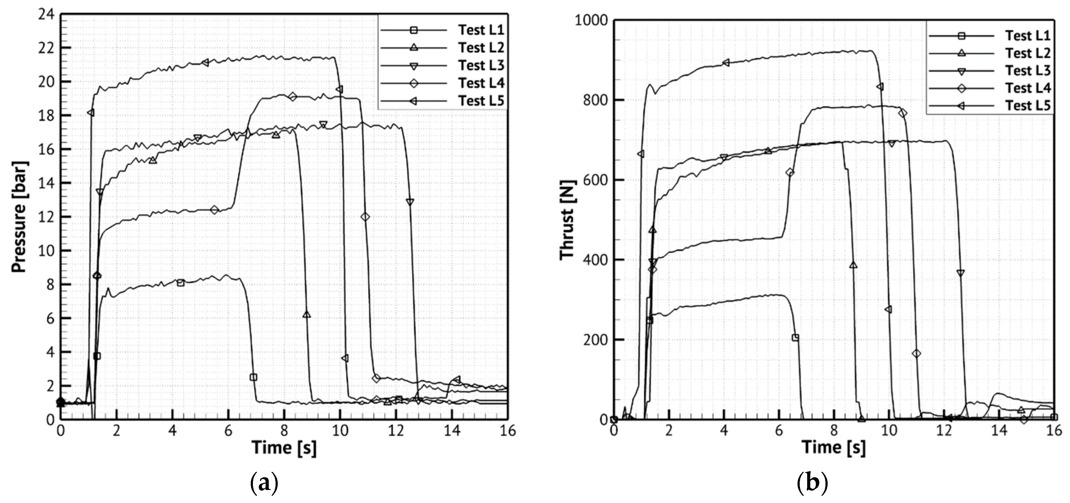
Figure 12 provides the temporal evolution of chamber pressure (a) and thrust (b) acquired for the different firing tests. Chamber pressure was not affected by throat diameter increase, since negligible ablation was measured after the firing tests. It is interesting noticing that pressure slightly increases and tends to a constant value during firing time; this behavior is opposite with respect to the previsions by HDC, since they were based on the regression rate law of the small-scale breadboard (Equation (2)). Due to higher measured regression rates with respect to the law presented in [6], even if on one side the temperature decreases in time due to decrease of MR from the optimum (see Figure 11), the higher paraffin mass-flow rate compensates this effect and the result is a nearly constant chamber pressure.
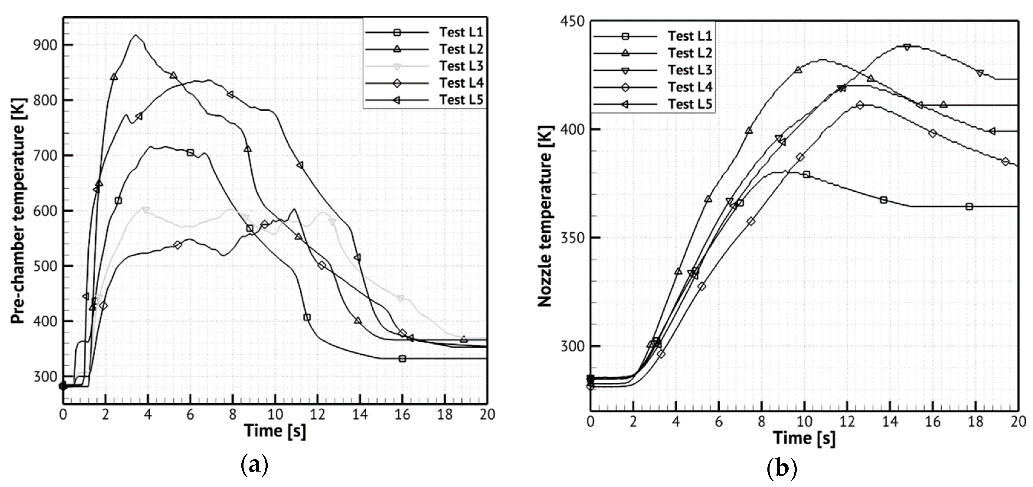
Figure 13 shows temperature acquisitions by a thermocouple located in the breadboard pre-chamber (a) and an embedded thermocouple in proximity of the nozzle throat (b)—(for details see Figure 7). For test L3, the pre-chamber TC did not acquire due to a paraffin occlusion of the hole.
The experimental nozzle material temperature levels recorded during test, in Figure 13b, justify the absence of ablation phenomena.
Table 6 reports the experimental breadboard performances. The time-averaged specific impulse is in line with the prevision made by the equilibrium calculation for each test conditions and thrust level is almost coherent with design predictions. It is important pointing out the behavior of the breadboard in the throttling test L4 (Figure 12), where thrust and pressure levels are steady for both the operating conditions and the transition appears stable without spikes and oscillations.
The combustion efficiency has been highlighted only for test L5, being, this operative point very close to the nominal one in terms of oxidizer mass flow. The estimation is based on the mean mixture ratio and has been calculated as the ratio between real and ideal values:
η c * = c r * c i d *

5. Conclusions

The design and testing activities of a novel 1000 N HRE breadboard have been presented. The breadboard, fed with gaseous oxygen and a paraffin-based fuel, showed a robust design and good performances. In particular, a stable combustion occurred in all the testing conditions including a wide range of pressure and mixture ratio. No significant chamber pressure oscillation was observed. The breadboard was also tested in order to verify throttling capabilities, oxidizer mass-flow rate was increased of about 35% during one of the firing test, leading to thrust increase of about 40%. Numerous experimental data were collected, including temperature of the flow in the pre-combustion chamber and temperature inside the nozzle material. The experimental input variables—e.g., oxidizer mass-flow rates—were in agreement with the test plan; the breadboard performances, in terms of thrust and pressure, were almost in line with test objectives. A higher fuel regression rate was experimentally found with respect to subscale results, due to different operating conditions which affected both gas properties and heat transfer to the fuel surface. At the end of the test campaign, the graphite nozzle throat showed no significant erosion, in contrast with the expectations associated with the pre-testing numerical predictions and literature investigations. The result was due to lower than expected wall temperatures and, therefore, heat transfer rate.
Further investigations are still required for a thorough assessment of the collected data. Other test campaigns will be necessary, in order to better assess the role of the mixture ratio on the fuel regression rate.

Author Contributions

Conceptualization, F.B.; methodology, F.B. and G.D.D.M.; formal analysis, D.C.; investigation, F.B., D.C., G.D.D.M., and S.M.; data curation; D.C.; writing—original draft preparation, D.C.; writing—review and editing, F.B., G.D.D.M.; visualization, D.C. and M.F.; supervision, R.S.; project administration, F.B.

Funding

This research was founded by the Italian Ministry of University of Research (MIUR), whose support is much appreciated, financed this project.

Acknowledgments

The authors would like to thank all the HYPROB-NEW hybrid development line project team in particular Giuseppe Spaziani, Valeria De Simone, Marco Invigorito, Gianpaolo Elia, Vito Salvatore, whose effort was significant for the advancements of the project. Moreover, we would like to express our gratitude to all the UniNA colleagues, in integration and testing activities, for their precious cooperation and Marotta Srl for the manufacturing of the components.

Conflicts of Interest

The authors declare no conflict of interest. The funders had no role in the design of the study; in the collection, analyses, or interpretation of data; in the writing of the manuscript, or in the decision to publish the results.

Nomenclature

a regression rate factor [-]
A t nozzle throat area [m2]
B blowing number [-]
c * characteristic velocity [m/s]
C B 1 blowing correction coefficient [-]
C f friction coefficient [-]
C f , r e f reference friction coefficient [-]
G port average mass flux [kg/m2-s]
h melt layer thickness [m]
h g convective heat transfer coefficient [W/m-K]
L fuel grain length [m]
m chamber pressure exponent
n oxidizer mass flux exponent
p c chamber pressure [Pa]
P d dynamic pressure [Pa]
Q ˙ c convective heat flux [W/m2]
Q ˙ r radiative heat flux [W/m2]
r ˙ surface regression rate [m/s]
r c l ˙ classical theory regression rate [m/s]
r e ˙ regression rate due to entrainment [m/s]
R 2 coefficient of determination [-]
T temperature [K]
T w a adiabatic wall temperature [K]
T w h hot gas wall temperature [K]
Greek Symbols
η combustion efficiency [-]
μ gas molecular viscosity [kg/m-s]
ρ density [kg/m3]
σ surface tension [N/m]
Subscripts
c chamber
g gas
i d ideal
l liquid
o x oxygen
r real
s solid
Acronyms
CEA Chemical Equilibrium with Application code
CFD Computational Fluid Dynamics
EDM Eddy Dissipation Model
HDC CIRA code
HDPE High Density Polyethylene
HRE Hybrid Rocket Engine
HTPB Hydroxyl Terminated Polybutadiene
MR Oxidizer to fuel Mixture Ratio
SST Shear Stress Transport
TRL Technology Readiness Level

References

  1. Altman, D.; Holzman, A. Overview and History of Hybrid Rocket Propulsion. In Fundamentals of Hybrid Rocket Combustion and Propulsion; Kuo, K., Chiaverini, M., Eds.; Progress in Astronautics and Aeronautics; AIAA: Reston, VA, USA, 2007; pp. 1–36. [Google Scholar]
  2. Karabeyoglu, A. Scale-up tests of high regression rate paraffin-based hybrid rocket fuels. J. Propuls. Power 2004, 20. [Google Scholar] [CrossRef]
  3. Carmicino, C.; Scaramuzzino, F.; Sorge, A. Trade-off Between Paraffin-Based and Aluminium-Loaded HTPB Fuels to Improve Performance of Hybrid Rocket Fed with N2O. Aerosp. Sci. Technol. 2014, 37, 81–92. [Google Scholar] [CrossRef]
  4. Kobald, M.; Schmierer, C.; Ciezki, H.K.; Schlechtriem, S.; Toson, E.; De Luca, L.T. Viscosity and Regression Rate of Liquefying Hybrid Rocket Fuels. J. Propuls. Power 2017, 33, 1245–1251. [Google Scholar] [CrossRef]
  5. Karabeyoglu, M.A.; Cantwell, B.J.; Altman, D. Development and Testing of Paraffin-Based Hybrid Rocket Fuels. In Proceedings of the 37th AIAA/ASME/SAE7ASEE Joint Propulsion Conference and Exhibit, Salt Lake City, UT, USA, 8–11 July 2001. [Google Scholar]
  6. Di Martino, G.D.; Mungiguerra, S.; Carmicino, C.; Savino, R.; Cardillo, D.; Battista, F.; Invigorito, M.; Elia, G. Two-Hundred-Newton Laboratory-Scale Hybrid Rocket Testing for Paraffin Fuel-Performance Characterization. J. Propuls. Power 2018, 35. [Google Scholar] [CrossRef]
  7. Bianchi, D.; Nasuti, F. Numerical Analysis of Nozzle Material Thermochemical Erosion in Hybrid Rocket Engines. J. Propuls. Power 2013, 29, 547–558. [Google Scholar] [CrossRef]
  8. Sutton, G.P.; Biblarz, O. Hybrid Propellant Rockets, Rocket Propulsion Elements, 7th ed.; John Wiley & Sons: Hoboken, NJ, USA, 2001; pp. 585–593. [Google Scholar]
  9. Karabeyoglu, A. Advanced Hybrid Rockets for Future Space Launch. In Proceedings of the Fifth European Conference for Aeronautics and Space Sciences, Munich, Germany, 1–5 July 2013. [Google Scholar]
  10. Ponomarenko, A. RPA Tool for Rocket Propulsion Analysis. In Proceedings of the Space Propulsion Conference, Cologne, Germany, 19–22 May 2014. [Google Scholar]
  11. Hill, P.G.; Peterson, C.R. Mechanics and Thermodynamics of Propulsion; Addison-Wesley: Boston, MA, USA, 1965. [Google Scholar]
  12. David, W. Hybrid Rocket Internal Ballistics; Chemical Propulsion Information Agency: Monterey, CA, USA, 1972. [Google Scholar]
  13. Altman, D.; Humble, R. Hybrid Rocket Propulsion Systems. In Space Propulsion Analysis and Design; Humble, R.W., Henry, G.N., Larson, W.J., Eds.; The McGraw-Hill Companies, Inc., Primis Custom Publishing: New York, NY, USA, 1995; pp. 403–441. [Google Scholar]
  14. Yang, V. Liquid Rocket Thrust Chambers: Aspects of Modeling, Analysis, and Design; AIAA: Reston, VT, USA, 2004; ISBN 1563472236. [Google Scholar]
  15. Cardillo, D.; Battista, F.; Elia, G.; Di Martino, G.D.; Mungiguerra, S.; Savino, R. Design and Testing of a Paraffin-Based Hybrid Rocket Demonstrator. In Proceedings of the Space Propulsion Conference, Seville, Spain, 14–18 May 2018. [Google Scholar]
  16. Saccone, G.; Piscitelli, F.; Gianvito, A.; Cosentino, G.; Mazzola, L. Manufacturing Processes of Paraffin Grains as Fuel for Hybrid Rocket Engines. In Proceedings of the 51st AIAA/ASME/SAE/ASEE Joint Propulsion Conference, Orlando, FL, USA, 27–29 July 2015. [Google Scholar]
  17. Kumar, C.P.; Kumar, A. A Numerical Study on the Regression Rate of Hybrid Rocket Motors Using a Combination of Enhancement Techniques. In Proceedings of the 48th AIAA/ASME/SAE/ASEE Joint Propulsion Conference Exhibit, Atlanta, GA, USA, 30 July–1 August 2012. [Google Scholar]
  18. Carmicino, C.; Sorge, R.A. Role of Injection in Hybrid Rockets Regression Rate Behavior. J. Propuls. Power 2005, 21, 606–612. [Google Scholar] [CrossRef]
  19. Marxman, G.A.; Wooldridge, C.E.; Muzzy, R.J. Fundamentals of Hybrid Boundary Layer Combustion. Prog. Astronaut. Aeronaut. 1964, 15, 485–522. [Google Scholar]
Figure 1. HDC code simplified design loop.
Aerospace 06 00089 g001
Figure 2. Pressure and thrust profiles in time (a) and thruster configuration from HDC (b).
Aerospace 06 00089 g002
Figure 3. Regression rate versus oxidizer mass-flux for the 200 N breadboard [6].
Aerospace 06 00089 g003
Figure 4. CIRA Hybrid 1000 N breadboard assembled (a), general arrangement (b).
Aerospace 06 00089 g004
Figure 5. Test rig layout.
Aerospace 06 00089 g005
Figure 6. 1000 N breadboard integrated on the test bench.
Aerospace 06 00089 g006
Figure 7. Embedded thermocouple positioning.
Aerospace 06 00089 g007
Figure 8. Breadboard during the firing test L1 (a) and L3 (b).
Aerospace 06 00089 g008
Figure 9. Paraffin grain before test (a) and after firing test L3 (b).
Aerospace 06 00089 g009
Figure 10. Regression rate versus oxidizer mass flux for all the tests.
Aerospace 06 00089 g010
Figure 11. Specific impulse and chamber temperature vs. MR at 2 × 10⁶ Pa.
Aerospace 06 00089 g011
Figure 12. Measured pressure in the post-chamber (a) and thrust (b) over firing time.
Aerospace 06 00089 g012
Figure 13. Measured pre-chamber temperature (a) and nozzle temperature (b) over firing time.
Aerospace 06 00089 g013
Table 1. SASOL® 0907 paraffin wax properties.
Melting Point [°C]Congealing Point [°C]Oil Content [%]Penetration at 25 °C [1/10 mm]
88–10283–940–1.54–10
Table 2. Nominal operating conditions.
Operating ConditionTest L1Test L2Test L3Test L4Test L5
Oxidizer mass-flow rate (kg/s)0.1200.2000.2000.140–0.2250.260
Firing time (s)68125 + 1 (transient) + 410
Table 3. Experimental data acquisitions.
DataTest L1Test L2Test L3Test L4Test L5
Effective firing time (s)5.67.511.49.7 (5.3 + 4.4)9.0
Effective oxidizer mass-flow rate (kg/s)0.1100.1950.1920.142–0.2150.243
Time-averaged fuel mass-flow rate (kg/s)0.9840.1520.1720.1770.2039
Time-averaged mixture ratio (-)1.121.291.11-1.20
Time-space-averaged ox mass-flux (kg/m2s)55.3572.3552.3753.369.94
Time-space averaged fuel regression rate (mm/s)1.912.532.492.62.99
Table 4. Expected regression rate obtained with Equation (2) and deviation with respect to experimental data.
Test IDExpected Regression Rate with Equation (2)Relative Deviation w.r.t. Experimental Data
Test L11.73−9.6%
Test L22.14−15.6%
Test L31.65−33.7%
Test L41.67−38.0%
Test L52.08−30.5%
Table 5. Expected regression rate obtained with Equation (3) and deviation with respect to experimental data.
Test IDExpected Regression Rate with Equation (3)Relative Deviation w.r.t. Experimental Data
Test L12.2618.4%
Test L22.9014.5%
Test L32.45−1.3%
Test L42.41−10.6%
Test L52.98−0.5%
Table 6. Experimental 1000 N breadboard performances.
QuantityTest L1Test L2Test L3Test L4Test L5
Time-averaged chamber pressure (MPa)0.791.591.671.23–1.902.09
Time-averaged thrust (N)291650679446–782893
Time-averaged specific impulse (s)142191190173204
Time averaged ηc*----0.94

