Fault Tolerant Control of an Experimental Flexible Wing


Abstract
1. Introduction
2. Input-Output Blending Based Modal Control
2.1. Modal Description of Linear Time-Invariant Systems
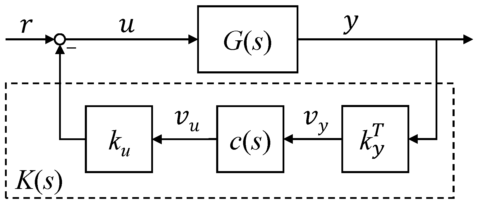
2.2. -Optimal Blending of Inputs and Outputs for Modal Control
3. Fault Detection Based Fault Tolerant Control Allocation
3.1. Fault Detection System
3.1.1. Linear Residual Filter Design
3.1.2. Residual Evaluation and Decision-Making
3.2. Fault Tolerant Control Allocation
4. The Flexible Wing
Modeling
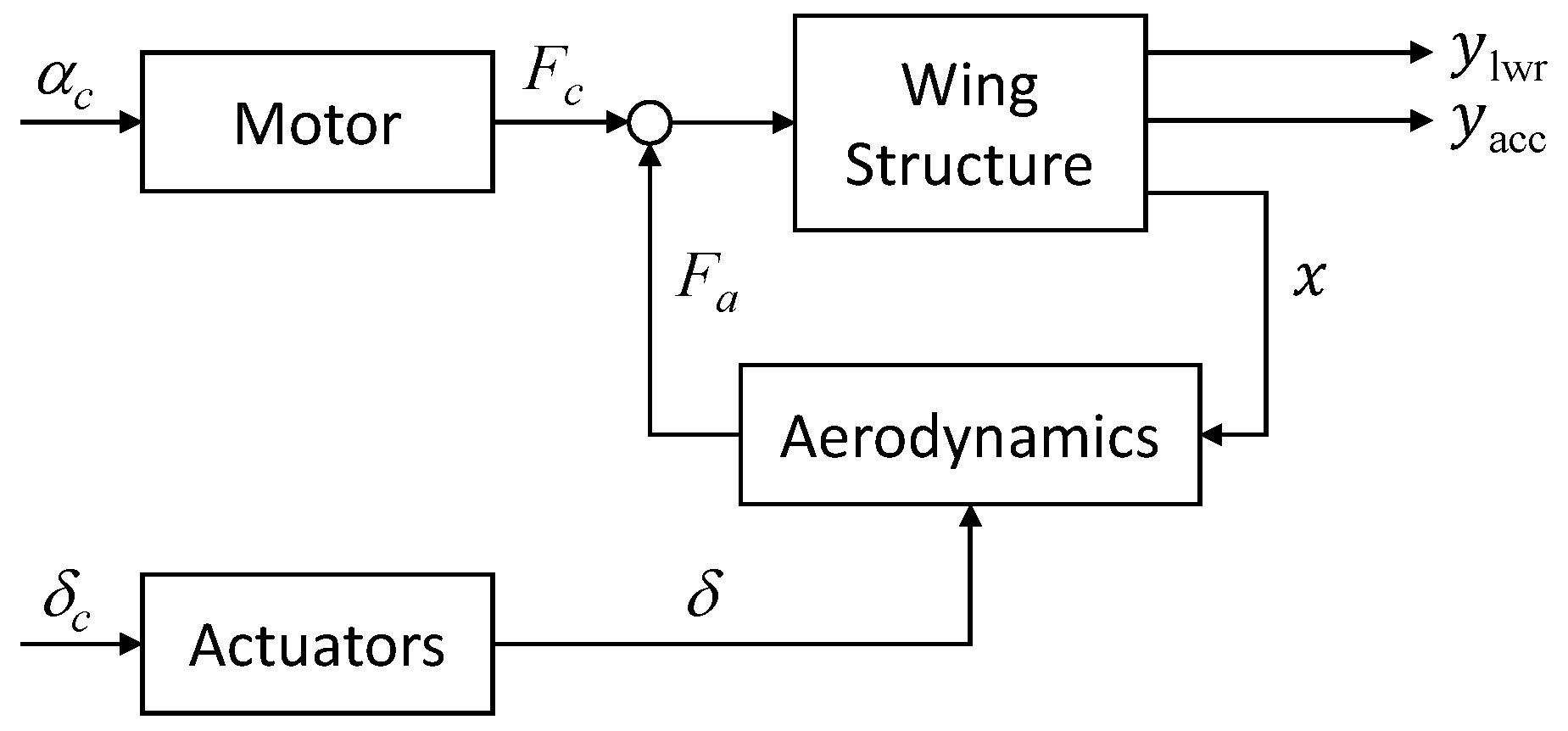
- (i)
- A structural model of the wing derived by modal analysis of the stiffness-optimized finite element model (FEM), which has been generated via the aeroelastic-tailoring process described [23]. Note that the structural model also includes rigid body dynamics in terms of the non-fixed pitching degree of freedom and considers only the seven flexible modes with the lowest natural frequency, that is, it consists 16 states in total.
- (ii)
- An aerodynamic model derived in frequency domain by means of the double lattice method, which considers also unsteady aerodynamic effects. To obtain a suitable state space model, a rational function approximation according to Roger [24] is carried out. Furthermore, the order of the approximated aerodynamic model is reduced to 20 by means of balance and truncation.
- (iii)
- Detailed models of the three control surface actuators, where each one features two states.
- (iv)
- A fourth-order pitch motor model identified via hardware tests.
5. Fault Tolerant Control System Design
5.1. Baseline Controller
 ) and closed-loop (
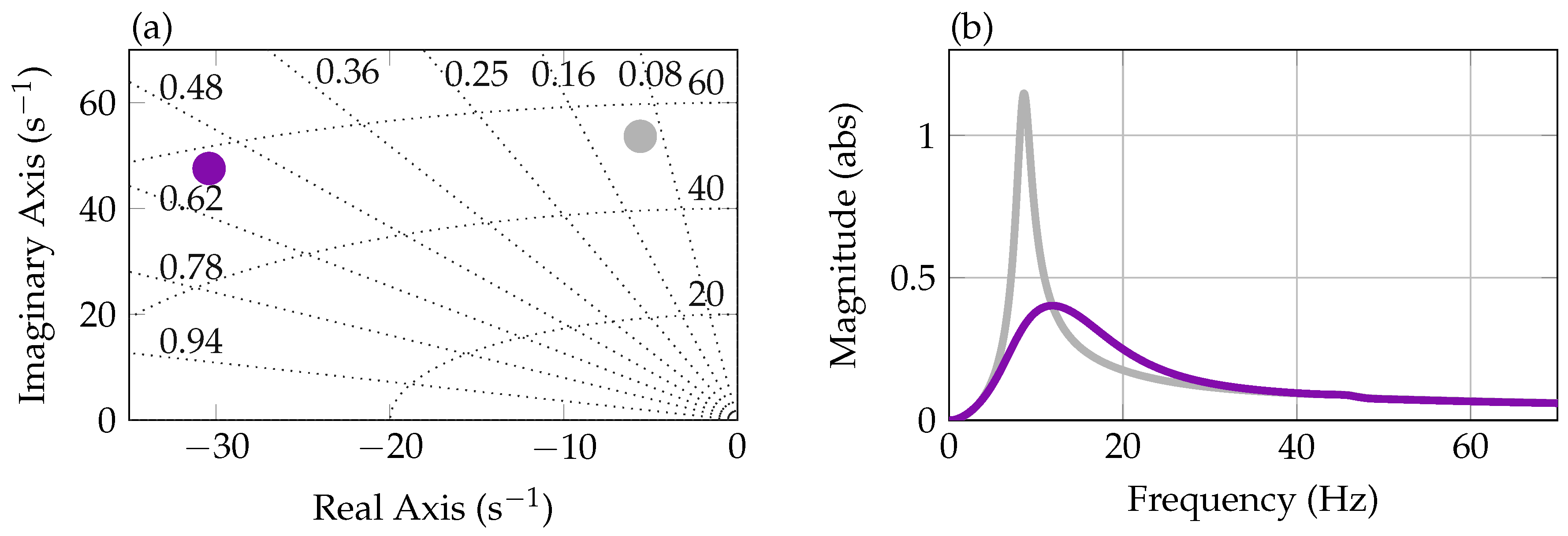
 ) pole location (positive imaginary axis only) for the first wing bending mode of the aeroelastic model is shown. It is clearly visible that the damping ratio of the first bending mode is increased from about 0.1 to about 0.55 using the SISO PI controller. Note again that the damping of the open-loop aeroelastic first wing bending mode (0.1) at 40 m/s wind speed is higher than the damping of the structural first wing bending mode (0.004) introduced in Section 4 due to the aerodynamics. In diagram (b) of Figure 6, a magnitude plot of the SISO open-loop wing model (
 ), that is, with blended inputs and outputs, is depicted. It shows the isolated first wing bending mode of the aeroelastic wing model at around 8 Hz. In the plot, also the magnitude of the closed-loop is shown (
 ). It confirms the modal damping increase when closing the loop and that no other peaks over the frequency range occur.
5.2. Fault Detection System
5.3. Fault Tolerant Control Allocation
6. Wind Tunnel Based Control System Validation
6.1. Baseline Controller Validation
 ). For the closed-loop experiment, the commanded deflections for the inner (
 ), mid (
 ) and outer (
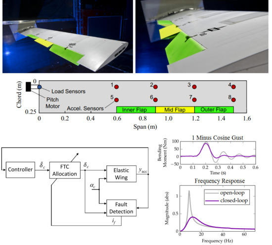
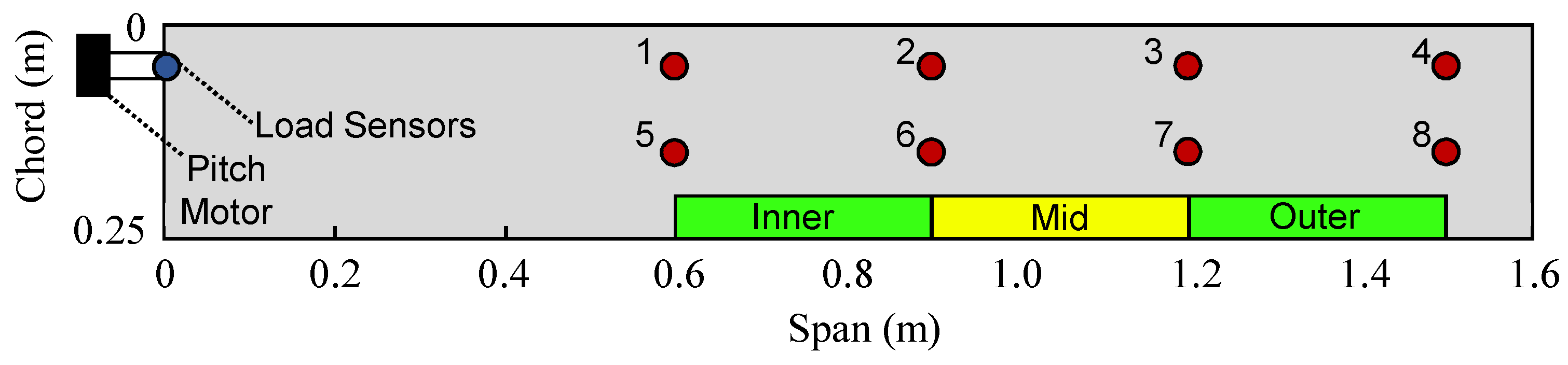
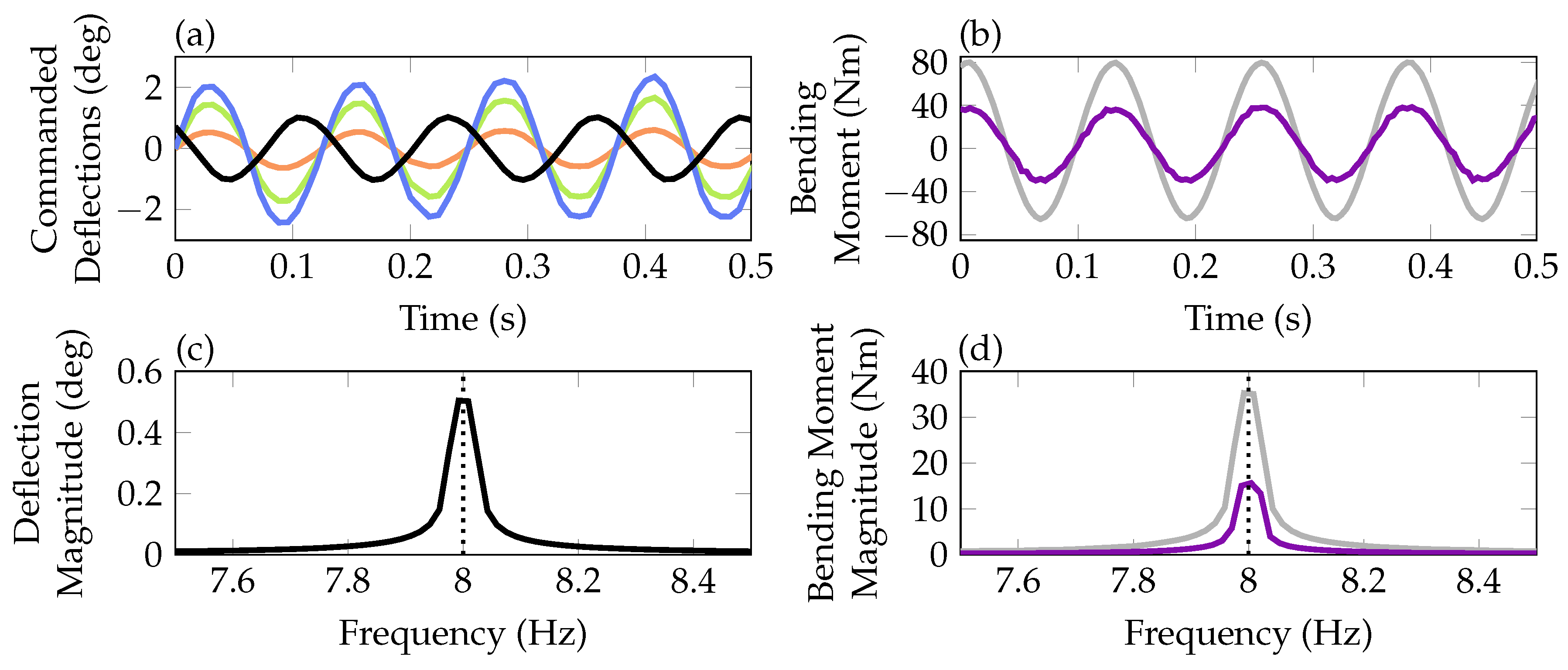
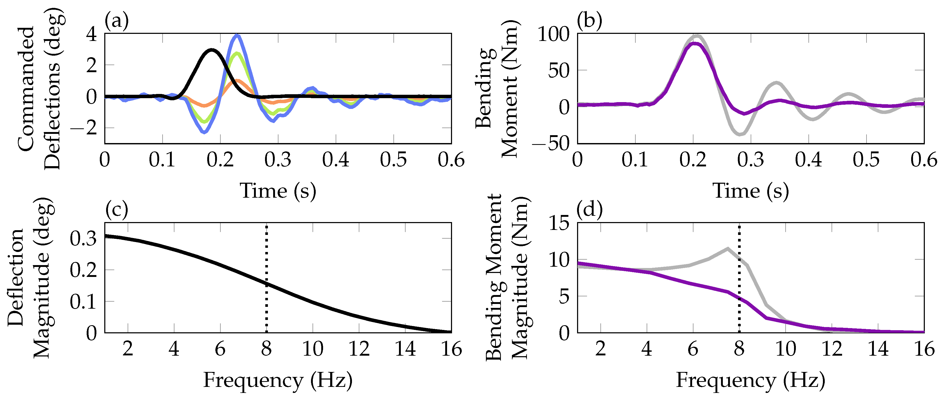
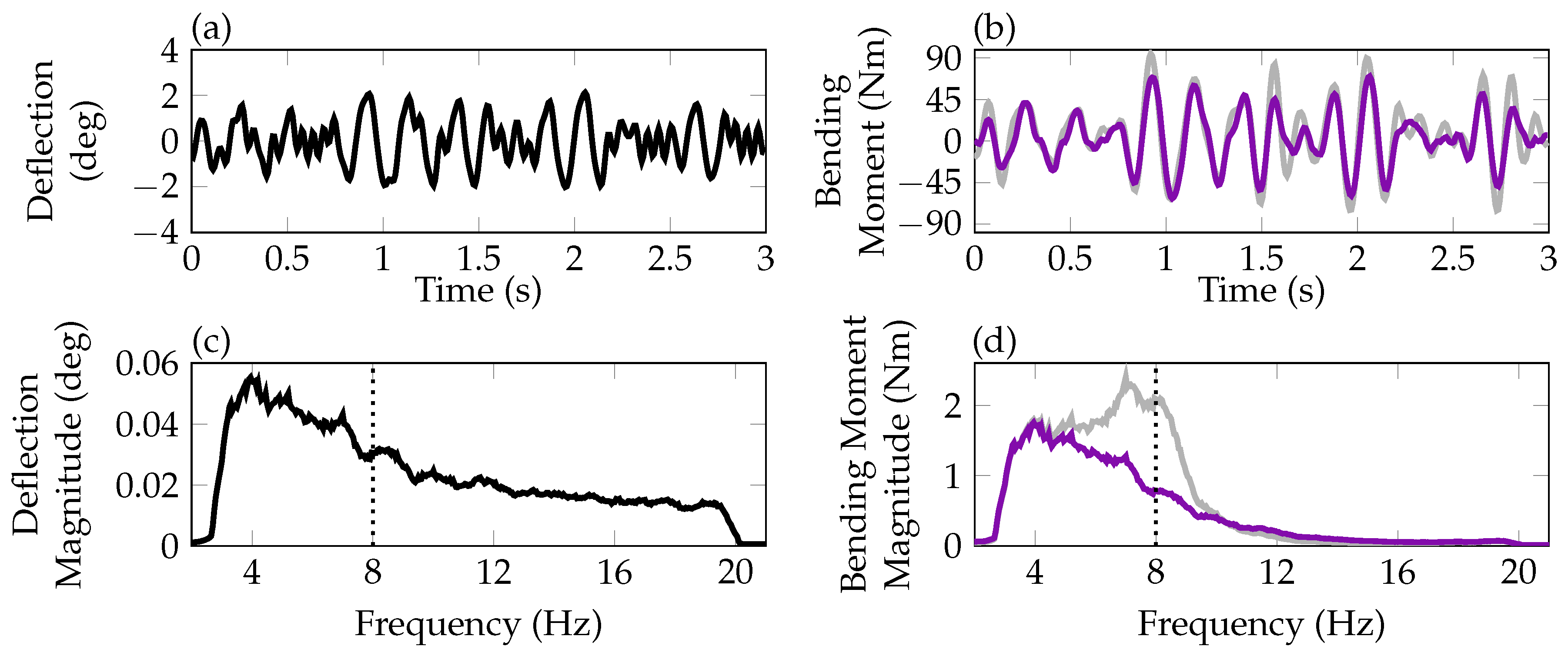
 ) control surface are depicted as well. Notably, the ratio between the three control surface commands in diagram (a) remains constant, confirming that the blending vectors are unchanged by the control allocation, which is active also during the fault free scenarios but not manipulating the commanded signals. As all three signals are equal zero in the open-loop experiment they are not shown. Diagram (b) compares the bending moment of the wing measured by sensors located at the wing root as depicted in Figure 4. Clearly, the moment is reduced when closing the loop confirming the load reduction capabilities of the baseline controller for an excitation of at 8 Hz. Note that the bending moment measurement is only used for control performance analyses and is not used in the feedback channels of the controller. Thereby it provides an independent variable to validate the performance of the algorithms. In diagrams (c) and (d) the results of Fast Fourier Transformations (FFTs) of the time domain data are shown. In diagram (c) the FFT of the pitch excitation signal shows the dominant magnitude at 8 Hz. The resonance frequency at 8 Hz is indicated by the vertical dotted line. Diagram (d) compares the FFTs of the measured bending moments in the open-loop and closed-loop. As in the time domain in diagram (b), the reduction in magnitude is clearly visible.) together with the closed-loop control surface commands are shown. The resulting reduction of the bending moment on the wing is visible in diagram (b), comparing open- () and closed-loop () responses. In the diagrams (c) and (d) the data is further analyzed using FFTs. Diagram (c) illustrates that the 1-cosine pitch signal excites the system up to a frequency of about 15 Hz, where the main energy is concentrated at the lower frequency range. In diagram (d) the peak in the open-loop response lies at around 8 Hz due to the undamped mode. The controller designed to increase the damping of this mode flattens the peak and reduce the output energy around 8 Hz.) and closed-loop () in diagram (b). FFTs of these two signals further reveals that energy around 8 Hz is clearly reduced in the closed-loop compared to the open-loop, see diagram (d). As for the 1-cosine excitation the main energy in the output signal is concentrated around 8 Hz in the open-loop although it is not in the input signal. This is due to the lowly damped first bending mode at 8 Hz. The increase of this damping by the controller leads to the reduction of energy in the output signal.
6.2. Fault Detection System Validation
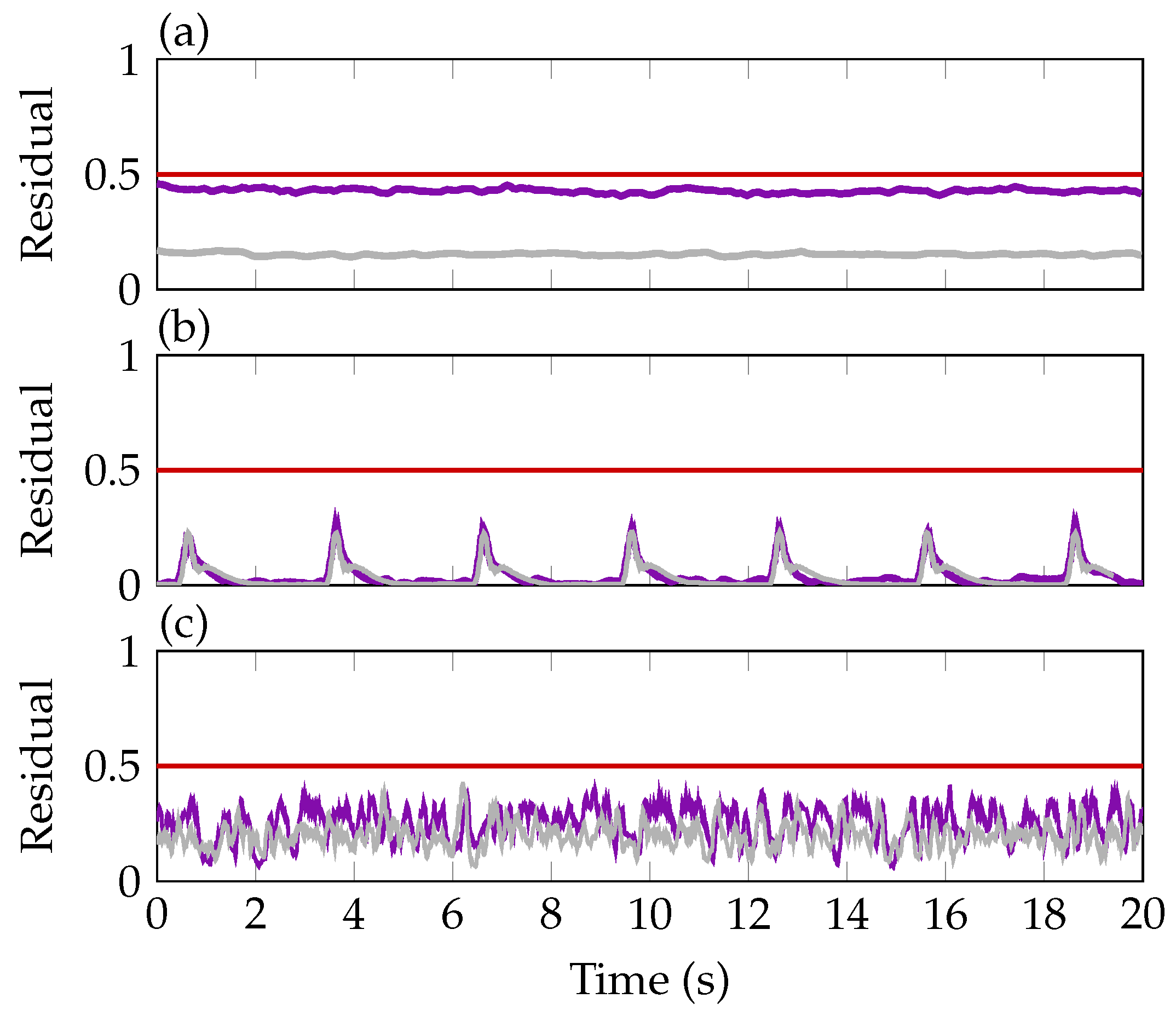
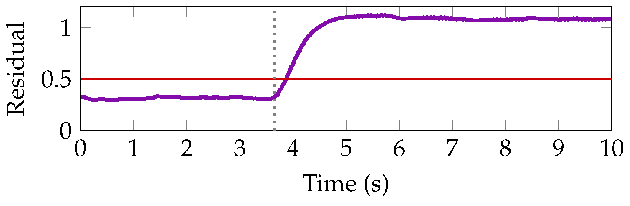
) and closed-loop (). The residual is higher when performing the experiments in the closed-loop as in these scenarios also control surface commands are present. This higher input energy unavoidably leads to a higher excitation of the residual due to modeling errors and uncertainties. Both signals, however, stay below the selected threshold of 0.5. Diagram (b) shows the residuals in open- and closed-loop during succeeding 1-cosine gust excitations of 3 deg. Again, the residual is slightly higher for the closed-loop experiment. In diagram (c), the residual responses in the open-loop and closed-loop to the noise excitation with a variance of 0.7 deg in amplitude and a frequency range between 3 Hz and 20 Hz is shown. In both cases the residual stay below the selected threshold of 0.5 and the closed-loop shows a slightly increased signal compared to the open-loop.6.3. Fault Tolerant Control Validation
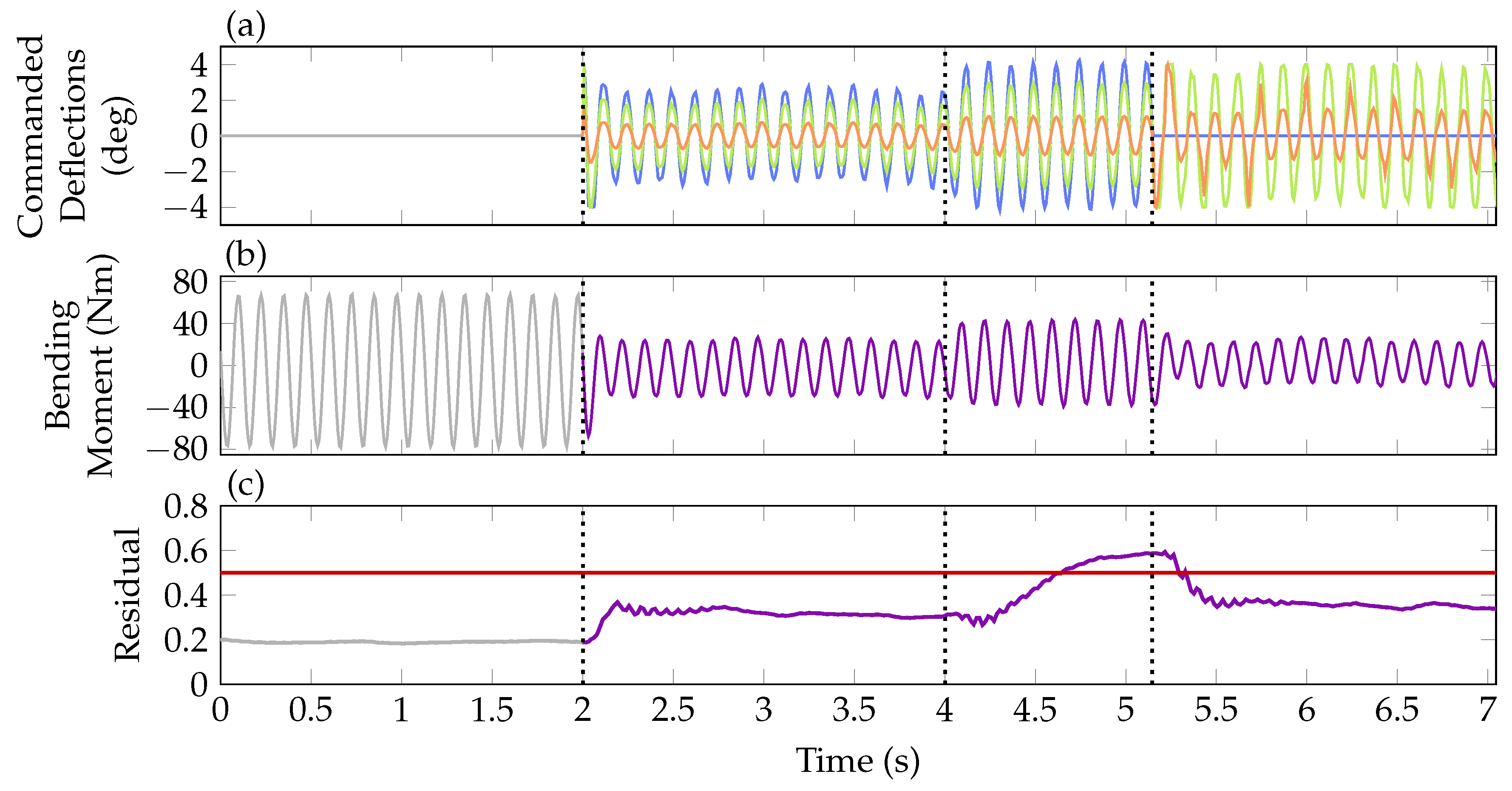
), mid () and outer () control surface counteracting the wing oscillations. In diagram (b) the measured wing root bending moment is depicted. As soon as the baseline controller is activated, the bending moment are reduced by about 50 %. The residual in diagram (c) is increased when activating the controller due to additionally present actuator inputs. At around 4 s the outer control surface is frozen at 2 deg. Note that the actual control surface positions are not plotted but the controller commands. As the fault is present but the controller has not been reconfigured, commands to the outer control surface are still present in the third part of the experiment, visible in diagram (a). Due to the frozen actuator position, the wing root bending moment increases as seen in diagram (b). Due to the increased control error, the baseline controller counteracts the fault, already achieving a reduction of the bending moment compared to the open-loop.) and mid () control surface in the fourth section. With this reconfiguration, the bending moment is reduced again as in the nominal baseline control configuration (see diagram (b)). Taking a closer look, however, it can be recognized that the bending moment resulting from the reconfigured control allocation, with only two flaps in operation, is slightly smaller than the one resulting from baseline control with all three flaps working. After some closer investigation, this curious result is traced back to the large free-play of the inner flap, which is around 1.5 deg. Hence, in the nominal case with the baseline controller, the inner flap is not deflected since the commanded deflections () given in diagram (a) of Figure 14 are within free-play. Obviously, this reduces nominal controller performance, which is confirmed in nonlinear simulations. In contrast, the reconfigured control allocation commands larger deflections to the inner flap yielding a smaller performance loss due to the increased operation outside of the free-play area. Note that the residual falls below its threshold after the reconfiguration. The constant mismatch between the commanded (0 deg) and actual actuator position (2 deg) is not visible due to the differentiating behavior in the fault to residual channel. Due to this phenomenon, the decision variable indicating if a fault is present on the actuator is held at 1 after the fault is confirmed at about 5 s. Finally, with this experiment, however, the fault tolerant control system including the reconfiguration of the control allocation in case of fault is successfully verified.7. Conclusions
Author Contributions
Funding
Acknowledgments
Conflicts of Interest
References
- Pusch, M.; Knoblach, A.; Kier, T. Integrated Optimization of Ailerons for Active Gust load alleviation. In Proceedings of the International Forum on Aeroelsticity and Structural Dynamics, St. Petersburg, Russia, 28 June–2 July 2015. [Google Scholar]
- Pusch, M. Allocation of distributed flaps for gust load alleviation. In Proceedings of the IEEE Conference on Control Technology and Applications, Mauna Lani, HI, USA, 27–30 August 2017; pp. 2120–2125. [Google Scholar] [CrossRef]
- Ossmann, D.; Poussot-Vassal, C. Minimal order disturbance estimator design for aircraft load alleviation control. In Proceedings of the IEEE Conference on Control Technology and Applications, Copenhagen, Denmark, 21–24 August 2018; pp. 787–793. [Google Scholar] [CrossRef]
- Goupil, P.; Boada-Bauxell, J.; Marcos, A.; Cortet, E.; Kerr, M.; Costa, H. AIRBUS efforts towards advanced real-time Fault Diagnosis and Fault Tolerant Control. In Proceedings of the 19th IFAC World Congress; Elsevier: Capetown, South Africa, 2014; pp. 3471–3476. [Google Scholar] [CrossRef]
- Ossmann, D.; Joos, H.D.; Goupil, P. Enhanced Sensor Monitoring to Maintain Optimal Aircraft Handling in Case of Faults. AIAA J. Guid. Control Dyn. 2017, 40, 3127–3137. [Google Scholar] [CrossRef]
- Danowsky, B.; Thompson, P.; Lee, D.C.; Brenner, M. Modal Isolation and Damping for Adaptive Aeroservoelastic Suppression. In AIAA Atmospheric Flight Mechanics Conference; AIAA: Boston, MA, USA, 2013. [Google Scholar] [CrossRef]
- Pusch, M. Aeroelastic Mode Control using H2-optimal Blends for Inputs and Outputs. In Proceedings of the Guidance, Navigation, and Control Conference, AIAA SciTech Forum; AIAA: Kissimmee, FL, USA, 2018. [Google Scholar] [CrossRef]
- Pusch, M.; Ossmann, D. -optimal Blending of Inputs and Outputs for Modal Control. Trans. Control Syst. Technol. 2018. submitted. [Google Scholar]
- Pusch, M.; Ossmann, D.; Luspay, T. Structured Control Design for a Highly Flexible Flutter Demonstrator. Aerospace 2019, 6, 27. [Google Scholar] [CrossRef]
- Frisk, E.; Nyberg, M. A minimal polynomial basis solution to residual generation for fault diagnosis in linear systems. Automatica 2001, 37, 1417–1424. [Google Scholar] [CrossRef]
- Varga, A. On computing least order fault detection filters using rational nullspace bases. In Proceedings of the 5th IFAC Symposium on Fault Detection, Supervision and Safety for Technical Processes; Elsevier: Washington, DC, USA, 2003. [Google Scholar] [CrossRef]
- Varga, A. Solving Fault Diagnosis Problems—Linear Synthesis Techniques; Springer International Publishing: Cham, Switzerland, 2017. [Google Scholar]
- Varga, A.; Ossmann, D. LPV-techniques based robust diagnosis of flight actuator faults. Control Eng. Pract. 2014, 31, 135–147. [Google Scholar] [CrossRef]
- Varga, A.; Ossmann, D.; Joos, H.D. A fault diagnosis based reconfigurable longitudinal control system for managing loss of air data sensors for a civil aircraft. In Proceedings of the 18th IFAC World Congress; Elsevier: Capetown, South Africa, 2014. [Google Scholar] [CrossRef]
- Argha, A.; Su, S.W.; Celler, B.G. Control allocation-based fault tolerant control. Automatica 2019, 103, 408–417. [Google Scholar] [CrossRef]
- Hamayun, M.T.; Edwards, C.; Alwi, H. A fault tolerant control allocation scheme with output integral sliding modes. Automatica 2013, 49, 1830–1837. [Google Scholar] [CrossRef]
- Pusch, M.; Ossmann, D.; Dillinger, J.; Kier, T.; Tang, M.; Lübker, J. Aeroelastic Modeling and Control of an Experimental Flexible Wing. In Proceedings of the AIAA Scitech 2019 Forum; AIAA: San Diego, CA, USA, 2019. [Google Scholar] [CrossRef][Green Version]
- Dillinger, J.; Meddaikar, Y.; Lübker, J.; Pusch, M.; Kier, T. Design and Optimization of an Aeroservoelastic Wind Tunnel Model. In Proceedings of the International Forum on Aeroelasticity and Structural Dynamics; IFASD: Savannah, GA, USA, 2019. [Google Scholar]
- Varga, A. The nullspace method a unifying paradigm to fault detection. In Proceedings of the IEEE Conference on Decision and Control, Shanghai, China, 15–18 December 2009. [Google Scholar] [CrossRef]
- Johansen, T.A.; Fossen, T.I. Control allocation—A Survey. Automatica 2013, 49, 1087–1103. [Google Scholar] [CrossRef]
- Schmid, C.; Biegler, L.T. Quadratic programming methods for reduced hessian SQP. Comput. Chem. Eng. 1994, 18, 817–832. [Google Scholar] [CrossRef]
- Krüger, W.R.; Dillinger, J.; Meddaikar, Y.; Lübker, J.; Tang, M.; Meier, W.; Pusch, M.; Kier, T. Design and Wind Tunnel Test of an Actively Controlled Flexible Wing. In Proceedings of the International Forum on Aeroelasticity and Structural Dynamics; IFASD: Savannah, GA, USA, 2019. [Google Scholar]
- Dillinger, J.; Klimmek, T.; Abdalla, M.; Gürdal, Z. Stiffness Optimization of Composite Wings with Aeroelastic Constraints. J. Aircr. 2013, 50, 1159–1168. [Google Scholar] [CrossRef]
- Roger, K.L. Airplane Math Modeling Methods for Active Control Design. In Proceedings of the 44th Structures and Materials Panel; Advisory Group for Aerospace Research and Development: Lisbon, Portugal, 1977; pp. 4.1–4.11. [Google Scholar]
- Govers, Y.; Böswald, M.; Lubrina, P.; Giclais, S.; Stephan, C.; Botargues, N. AIRBUS A350XWB Ground Vibration Testing: Efficient techniques for customer oriented on-site modal identification. In Proceedings of the International Conference on Noise and Vibration Engineering; Katholieke Universiteit Leuven: Leuven, Belgium, 2014; pp. 2503–2516. [Google Scholar]
- Böswald, M.; Schwochow, J.; Jelicic, G.; Govers, Y. New Concepts for Ground and Flight Vibration Testing of Aircraft based on Output-Only Modal Analysis. In Proceedings of the 7th International Operational Modal Analysis Conference; Shaker Verlag: Ingolstadt, Germany, 2017; pp. 15–34. [Google Scholar]
- Jelicic, G.; Schwochow, J.; Govers, Y.; Hebler, A.; Böswald, M. Real-time assessment of flutter stability based on automated output-only modal analysis. In Proceedings of the International Conference on Noise and Vibration Engineering; Katholieke Universiteit Leuven: Leuven, Belgium, 2014; pp. 3693–3706. [Google Scholar]
- Jelicic, G.; Schwochow, J.; Govers, Y.; Sinske, J.; Buchbach, R.; Springer, J. Online Monitoring of Aircraft Modal Parameters during Flight Test based on permanent Output-Only Modal Analysis. In Proceedings of the 58th AIAA/ASCE/AHS/ASC Structures, Structural Dynamics, and Materials Conference; AIAA: Grapevine, TX, USA, 2017. [Google Scholar] [CrossRef]
- Varga, A. Fault detection and isolation of actuator failures for a large transport aircraft. In Proceedings of the CEAS European Air and Space Conference; CEAS: Berlin, Germany, 2007. [Google Scholar]
- Poussot-Vassal, C.; Demourant, F.; Lepage, A.; Bihan, D.L. Gust Load Alleviation: Identification, Control, and Wind Tunnel Testing of a 2-D Aeroelastic Airfoil. IEEE Trans. Control Syst. Technol. 2017, 25. [Google Scholar] [CrossRef]
- Lepage, A.; Huvelin, F.; Bihan, D.L.; Poussot-Vassal, C.; Brion, V.; Naudin, P.; Rantet, E. Experimental investigation and control of gust load response in transonic flow. In Proceedings of the 3AF Greener Aviation Conference; CCSD: Brussels, Belgium, 2016. [Google Scholar]
- Certification Specifications and Acceptable Means of Compliance for Large Aeroplanes, CS25, Amendment 16; Technical report; European Aviation Safety Agency: Cologne, Germany, 2015.


 ) and closed-loop () pole location of the wing’s first bending mode depicted in (a). Magnitude plot of the wing model augmented with the blending vectors () in (b) together with the magnitude of closed-loop ().
) and closed-loop () pole location of the wing’s first bending mode depicted in (a). Magnitude plot of the wing model augmented with the blending vectors () in (b) together with the magnitude of closed-loop ().
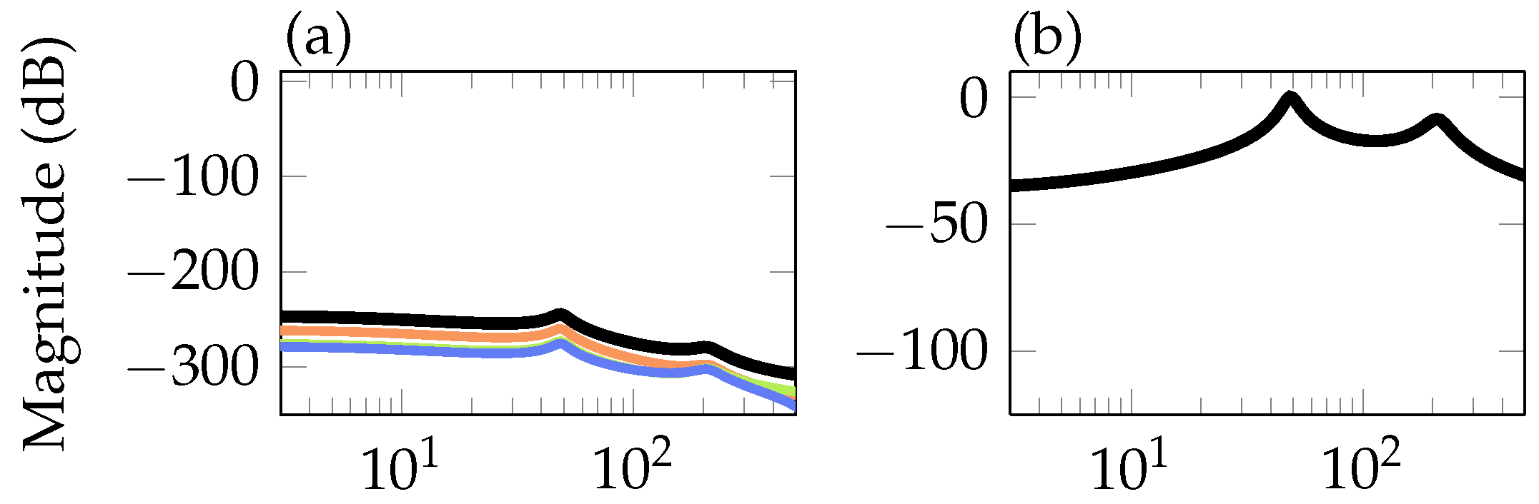
) and closed-loop () pole location of the wing’s first bending mode depicted in (a). Magnitude plot of the wing model augmented with the blending vectors () in (b) together with the magnitude of closed-loop (). ), mid (), outer () control surfaces to residual and from pitch motor command to the residual () in (a) and from fault to residual in (b).
), mid (), outer () control surfaces to residual and from pitch motor command to the residual () in (a) and from fault to residual in (b).
), mid (), outer () control surfaces to residual and from pitch motor command to the residual () in (a) and from fault to residual in (b).
 ) is depicted. In (b,d) the resulting open-loop () and closed-loop () bending moments are compared. Additionally, closed-loop inner (), mid () and outer () control surface commands are shown in (a).
) is depicted. In (b,d) the resulting open-loop () and closed-loop () bending moments are compared. Additionally, closed-loop inner (), mid () and outer () control surface commands are shown in (a).
) is depicted. In (b,d) the resulting open-loop () and closed-loop () bending moments are compared. Additionally, closed-loop inner (), mid () and outer () control surface commands are shown in (a). ) is depicted. In (b,d) the open-loop () and closed-loop () bending moments are compared. Additionally, closed-loop inner (), mid () and outer () control surface commands are shown in (a).
) is depicted. In (b,d) the open-loop () and closed-loop () bending moments are compared. Additionally, closed-loop inner (), mid () and outer () control surface commands are shown in (a).
) is depicted. In (b,d) the open-loop () and closed-loop () bending moments are compared. Additionally, closed-loop inner (), mid () and outer () control surface commands are shown in (a). ) is depicted, while in (b,d) the open- () and closed-loop () bending moment is compared.
) is depicted, while in (b,d) the open- () and closed-loop () bending moment is compared.
) is depicted, while in (b,d) the open- () and closed-loop () bending moment is compared. ) and closed-loop () experiments for sinusoidal excitation (a), 1-cosine gust excitations (b) and noise excitations (c) compared to the threshold (
 ).
) and closed-loop () experiments for sinusoidal excitation (a), 1-cosine gust excitations (b) and noise excitations (c) compared to the threshold ().
).
) and closed-loop () experiments for sinusoidal excitation (a), 1-cosine gust excitations (b) and noise excitations (c) compared to the threshold (). ).
).
).
). ), mid () and outer () control surface in (a), measured bending moment in (b) and the residual with its threshold () in (c). In (b,c), open-loop operation is indicated by () and closed-loop operation by ().
), mid () and outer () control surface in (a), measured bending moment in (b) and the residual with its threshold () in (c). In (b,c), open-loop operation is indicated by () and closed-loop operation by ().
), mid () and outer () control surface in (a), measured bending moment in (b) and the residual with its threshold () in (c). In (b,c), open-loop operation is indicated by () and closed-loop operation by ().
© 2019 by the authors. Licensee MDPI, Basel, Switzerland. This article is an open access article distributed under the terms and conditions of the Creative Commons Attribution (CC BY) license (http://creativecommons.org/licenses/by/4.0/).
Share and Cite
Ossmann, D.; Pusch, M. Fault Tolerant Control of an Experimental Flexible Wing. Aerospace 2019, 6, 76. https://doi.org/10.3390/aerospace6070076
Ossmann D, Pusch M. Fault Tolerant Control of an Experimental Flexible Wing. Aerospace. 2019; 6(7):76. https://doi.org/10.3390/aerospace6070076
Chicago/Turabian StyleOssmann, Daniel, and Manuel Pusch. 2019. "Fault Tolerant Control of an Experimental Flexible Wing" Aerospace 6, no. 7: 76. https://doi.org/10.3390/aerospace6070076
APA StyleOssmann, D., & Pusch, M. (2019). Fault Tolerant Control of an Experimental Flexible Wing. Aerospace, 6(7), 76. https://doi.org/10.3390/aerospace6070076