Article

Hybrid Rocket Underwater Propulsion: A Preliminary Assessment

1
Aerospace and Mechanical Engineering, Korea Aerospace University, Goyang 10540, Korea
2
Agency for Defense Development, Daejeon 34186, Korea
*
Author to whom correspondence should be addressed.
Aerospace 2019, 6(3), 28; https://doi.org/10.3390/aerospace6030028
Submission received: 28 January 2019 / Revised: 17 February 2019 / Accepted: 22 February 2019 / Published: 6 March 2019

Abstract

:
This paper presents an attempt to use the hybrid rocket for marine applications with a 500 N class hybrid motor. A 5-port high density polyethylene (HDPE) fuel grain was used as a test-bed for the preliminary assessment of the underwater boosting device. A rupture disc preset to burst at a given pressure was attached to the nozzle exit to prevent water intrusion where a careful hot-firing sequence was unconditionally required to avoid the wet environment within the chamber. The average thrust level around 450 N was delivered by both a ground test and an underwater test using a water-proof load cell. However, it was found that instantaneous underwater thrusts were prone to vibration, which was due in part to the wake structure downstream of the nozzle exit. Distinctive ignition curves depending on the rupture disc bursting pressure and oxidizer mass flow rate were also investigated. To assess the soft-start capability of the hybrid motor, the minimum power thrust, viewed as the idle test case, was evaluated by modulating the flow controlling valve. It was found that an optimum valve angle, delivering 16.3% of the full throttle test case, sustained the minimum thrust level. This preliminary study suggests that the throttable hybrid propulsion system can be a justifiable candidate for a short-duration, high-speed marine boosting system as an alternative to the solid underwater propulsion system.

1. Introduction

Underwater propulsion systems using conventional chemical rockets are uncommon and quite rare because of their short operating time, high noise, non-stealthiness, and shallow water depth operability with respect to the screw propeller driven system. These result from the limitations of a hot gas jet propulsive mechanism, which differs from the mechanical driver device where two-phase flow and high water-to-gas density ratios are present at the exit of the convergent/divergent nozzle, complicating the flow structure [1,2]. Mechanical driver devices, i.e., screw propellers, are usually driven by diesel engines, gas turbines, or even nuclear reactors for marine vessels, while, with the exception of rare trials using rocket propulsion, compressed heated air, electric motors, monopropellants, and gas turbines are used mostly for torpedoes. Modern marine vehicle development, either for watercrafts or torpedoes, focuses on speed augmentation, longer range and noise reduction, and additional depth increase for the underwater apparatus [3]. None of these factors are favorable for rocket application for marine propulsion, except for the speed augmentation, since the objective of a high-speed exhaust gas jet is a means of propulsion rather than noise reduction [4]. If a short-range and high-speed vehicle is enough for tactical purpose without taking any countermeasure for the noise, the underwater rocket propulsion could be an answer [4,5,6].
From the 20th century until today, marine propulsion designers and engineers have worked to increase torpedo speeds such that the modern high performing torpedo generally operates at around 50 knots. It is known that the increase of necessary power is proportional to the cubic of the rotational shaft speed, and therefore 240% increase in power output is required for a speed increase from 45 to 60 knots with a mechanically driven screw propeller [5,6]. Thus, rocket propulsion has been sporadically considered even up to the present time. From the first US Navy trial of the Ericsson rocket [4] proposed in the early 1880s to the recent “supercavitating rocket” [7], the underwater rocket has its own heritage with respect to the conventional torpedo in terms of cost, lack of moving parts, simplicity, minimal preparation, low maintenance, and low weight, depending on the rocket type. Research interest in high-speed torpedoes relying on solid propellant rockets increased in the past mid-twentieth century following World War II due to their speed, low cost, reliability, and negligible pre-launch preparation requirements [4]. To the authors’ knowledge, projects such as HEYDAY [4], CAMROSE [4,5] for anti-torpedo mission shown in Figure 1a, and BOOTLEG [4,5] for anti-ship missions were the earliest rocket-propelled torpedo studies conceived by the British since World War II. However, these projects were all abandoned due to the lack of financial support, which instead prioritized noise reduction studies. The focus of this study is not on supercavitating rockets nor on torpedo applications. Rather, the work proposed in this paper is focused on conventional chemical rocket propulsion systems for marine vessels.
In addition to a pure underwater main propulsion device, a rocket can also be envisaged as an auxiliary propulsion device for boosting the already running watercraft for some duration when used together with the conventional screw propeller driven system [8,9,10,11,12]. If a further rocket thrust variation is achievable, it would increase the mission flexibility of a marine vessel. It is also important to mention that thrust control for a soft-start is essential for marine vessels because the sudden acceleration in the start-up stage is dangerous, since it can disrupt the balance of the marine vehicle. Hence, the throttable rocket propulsion system can not only be applied to conventional vessels but also to high-speed vessels, which can be faster than the speed of ”Ghost” (50 knots), built by Juliet Marine System shown in Figure 1b, which uses a gas turbine based engine [13].
Until now, there has been no systematic classification of solid, liquid, and hybrid rockets for underwater environments. Marine propulsion using a solid propellant rocket has two main drawbacks: (1) the lack of thrust modulation capability with respect to hybrid and liquid counterparts; and (2) the low thrust level required for somewhat longer underwater operations. For the former, a lack of thrust modulation capability by means of propellant feed rate is a key classical drawback of solid propellant rockets since the thrust controllability is not frequently demanded for solid propellant systems. For the latter, solid propellant underwater propulsion systems have no choice but to have low thrust levels because these solid propellant rockets are forced to have “end-burning” grain configurations for prolonged operation time. The enlargement of propellant grain diameter required for a tubular port solid propellant grain is not a good solution for increasing the thrust level or for increasing the operating time because the drag force is increased as the square of the diameter. Concerning the liquid propellant rocket, it is obvious that its relatively heavy weight, large dimension, and complicated plumbing system are not very effective for underwater application.
Meanwhile, with its thrust controllability, the hybrid rocket used to be known as a cost-saving rocket with many advantages in terms of insensitivity of fuel, multiple shut on/off capability, easy handling, and environmental friendliness compared to solid and liquid propellant rockets. In addition, a typical hybrid propellant system can achieve a higher specific impulse than a solid propellant system, even though the belief that the hybrid propulsion system has a lower thrust/weight ratio than the solid propulsion system due to the addition of an oxidizer tank is still controversial in the field. Nonetheless, the throttleability of a propulsion system using a solidified fuel by means of a single oxidizer flow is very attractive since it reduces tremendous plumbing unlike conventional liquid bi-propellant systems. Owing to this, the underwater hybrid rocket can be an attractive alternative to solid or liquid counterparts, not to mention a safer alternative. Furthermore, common solid fuels used in the hybrid rocket propulsion system are suitable in humid environments due to the moisture-resistance of these fuels. From this point of view, a novel application of a hybrid rocket propulsion system for underwater application is introduced in this paper.
This study aimed to demonstrate the feasibility of the hybrid rocket application in an underwater environment rather than underlying interests on motor performance, e.g., use of high performing cryogenic oxidizers like liquid oxygen (LOX) [14,15,16] and use of high regression rate fuels with energetic particle addition [16,17,18] or swirl assisted injectors [19,20]. For this reason, nitrous oxide (N2O) was selected as the oxidizer since it does not require an additional pressurization system, while high density polyethylene (HDPE) was selected as the fuel since HDPE is known to be easily accessible for academic purposes in laboratory scale experiments. This is one of the simplest and most compact hybrid propulsion systems that can minimize the vehicle weight and the number of components. A series of hot firing tests was conducted to demonstrate the feasibility of the hybrid rocket application in an underwater environment where the 500 N class lab-scale hybrid rocket motors were used together for the underwater experimental set-up. A rupture disc was attached to the nozzle exit during each test to prevent the intrusion of water. Special emphasis was also placed on investigating the oxidizer supply timing and ignition characteristics. We also investigated the feasibility of an underwater hybrid rocket system in terms of full power thrust and factors to be assessed for minimum power thrust, i.e., the idle case.

2. Underwater Setup

2.1. Underwater Experimental System

Figure 2 shows the schematic of the experimental setup for the 500 N class lab-scale hybrid rocket motor used for the static-tests. The experimental setup of each unit was composed of an oxidizer feed system, ignition system, data acquisition (DAQ) system, and the hybrid rocket motor, where the unit number 8 represented the water filled tank. For the ground test, the hybrid motor was out of the water tank, while for the underwater test, a supplemental cap plugged in the rocket nozzle exit and the water filled tank accommodating the hybrid motor were additionally used.
The cross-sectional view of the lab-scale hybrid motor used both for ground and underwater combustion experiments is shown in Figure 3a. From the head-end, a shower head injector, pre-chamber, fuel grain, post-combustion chamber and a water-cooled copper nozzle used to prevent over-heating of the environment were all attached in-line making a total motor length of 457 mm. Pressure transducers were each mounted in the pre-chamber and post-chamber for static pressure measurement with a K type thermocouple to monitor the temperature level in the nozzle section. Figure 3b is an outer tank view showing the vertical transfer line, nozzle cooling line, and a cap plugged into the nozzle exit with the motor unit. The supplemental cap for the underwater firing test comprised a rupture disc provided by FDC Co. Ltd. (shown in Figure 4a,b) that not only prevented the intrusion of water during the ignition stage, but also blasts at a given preset chamber pressure.
Figure 5 shows the oxidizer supply system for the ground and underwater experiments. All combustion experiments were conducted in blow down mode using liquid N2O by assuming no spontaneous mixing of the liquid and vapor during the evacuation of N2O from the tank. The oxidizer run tank was charged from two N2O tanks, and the oxidizer mass flow rate was measured by a load cell capable of measuring the weight change in the run tank. Additionally, plumbing was installed at the bottom of the oxidizer run tank so that the liquid N2O could be discharged in advance of gas phase N2O.

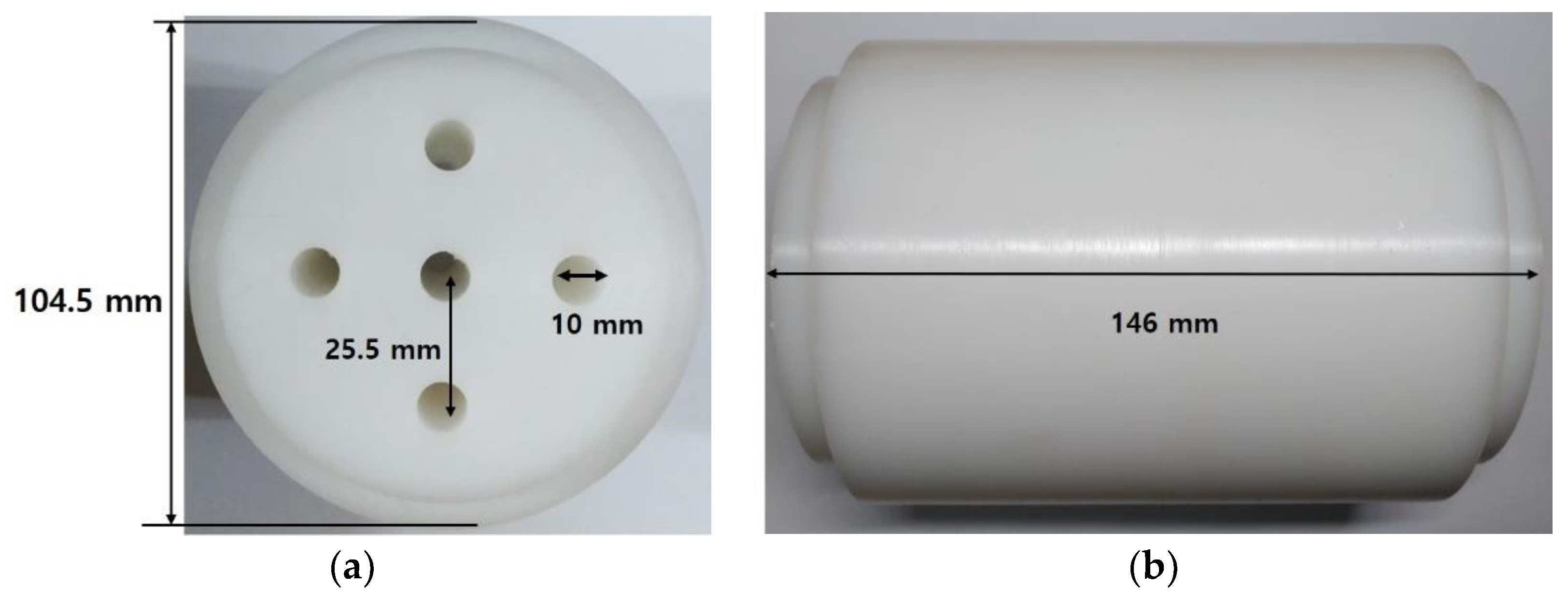
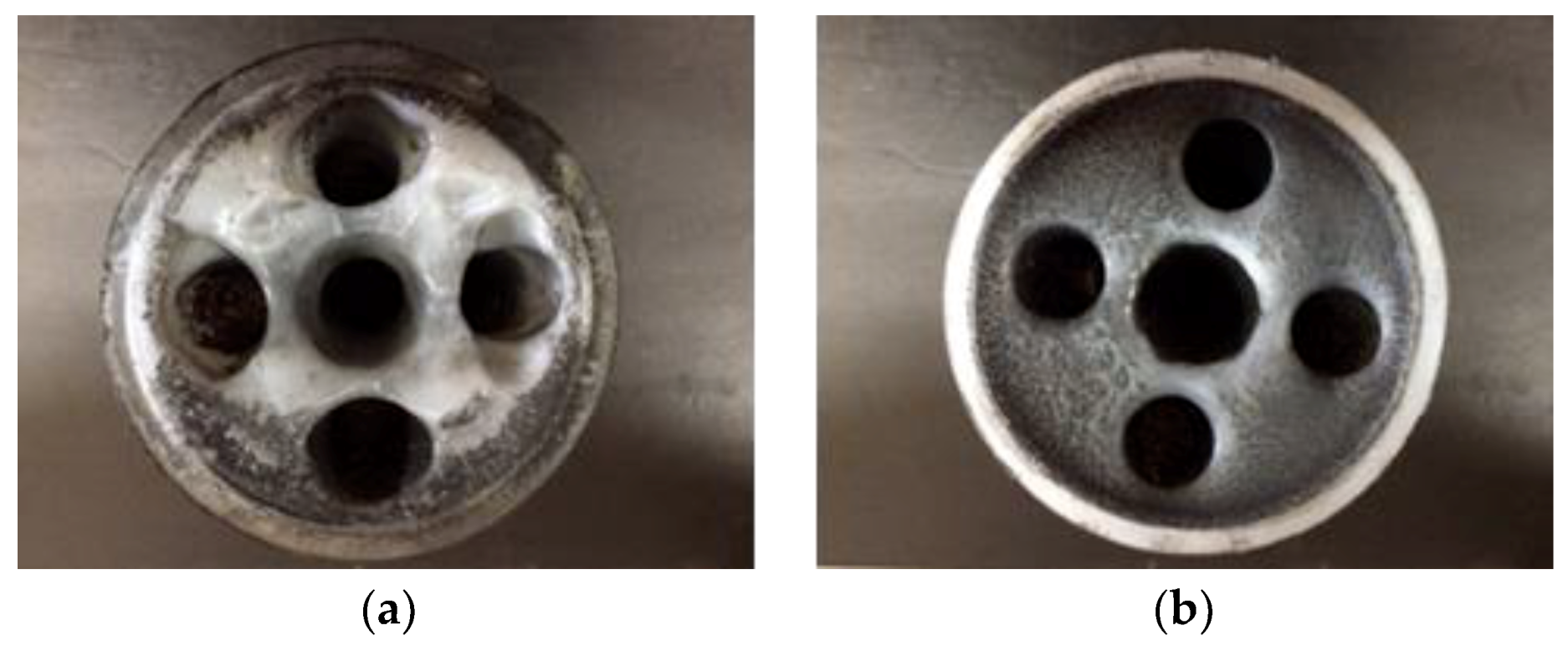
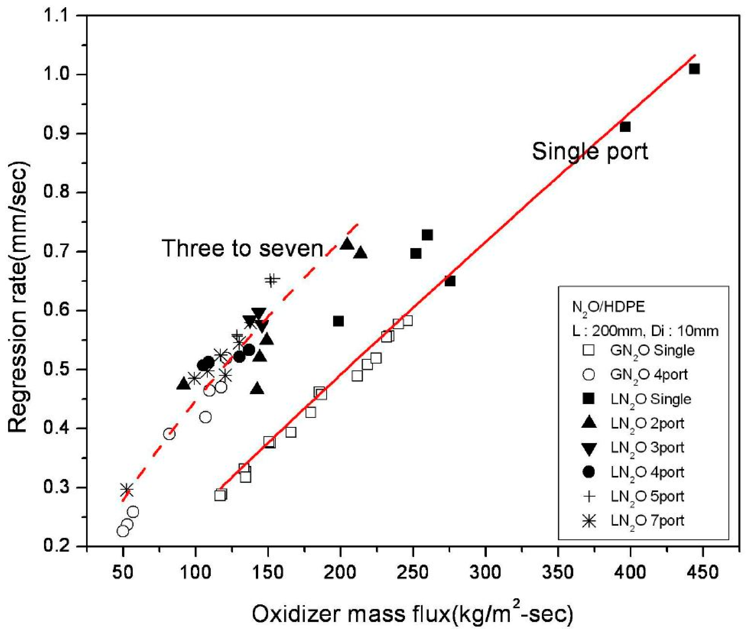
2.2. Internal Ballistics

Table 1 lists some specifications of the basic experimental conditions and fuel geometry, where liquid nitrous oxide and HDPE were used for the oxidizer and solid fuel, respectively. A 5-port fuel grain was chosen to shorten the motor length instead of a single port grain to avoid an unrealistically long motor unit. Figure 6a,b shows the front and side view of the 5-port grain, respectively, with an initial port diameter of 10 mm and distance between port’s centers of 25.5 mm before the test. On the other hand, Figure 7a,b each shows the front and rear view of the grain after combustion. One can notice that with a burning time of 10 s, there was no merging event between ports during the hot firing tests. An in-depth analysis on port merging can be found in reference [21].
In a typical hybrid rocket internal ballistic design, knowledge of the fuel regression rate is of primary importance and crucial for the right performance prediction. Therefore, for the design of the 500 N class motor, the empirical regression rate of our previous works [21,22,23,24] for multi-port grains were used. The empirical relation used in this study for the overall regression rate, r ˙ ¯ , was a time–space (burning time–fuel length) averaged value:
r ˙ ¯ = 0.01 G ¯ o 0.83
The overall regression rate can be evaluated with the measured fuel mass difference Δ m , initial and final port radius ( R p i and R p f ) from the cross-section areas ( A p i and A p f ), the port number N, the fuel density ρ , and the fuel length L by following equations:
Δ m N ρ = ( A p f A p i ) L
r ˙ ¯ R p f R p i t b
G ¯ o is the averaged oxidizer mass flux defined as:
G ¯ o 4 m ˙ ¯ o π ( R p i + R p f ) 2 N
where m ˙ ¯ o is the averaged oxidizer mass flow rate. The complete details of the procedure can be found in references [21,22,23,24]. Figure 8 shows the N2O/HDPE multi-port regression rate correlations [22] where Equation (1) is the empirical relation corresponding to “three to seven” ports shown by the red dotted line. It was found that three to seven-port HDPE laboratory scale grain can be fitted by a single empirical regression rate. Results of ground and underwater hot-firing experiments using the 5-port grain motor are shown in Section 3.1 and idle cases in Section 3.4.

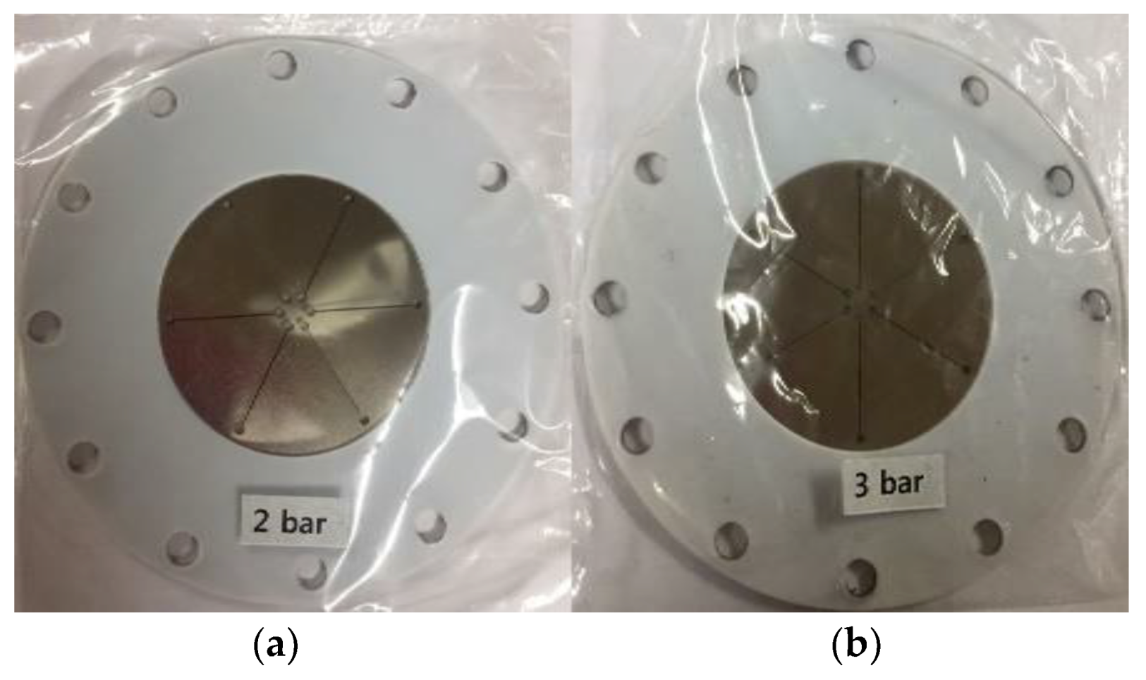
2.3. Underwater Subsystem (Ignition, Flow Control, Thrust Measurement)

Concerning the ignition system, Potassium Nitrate/Sorbitol (KNSB), widely used in semi-professional rocketry, was used as a pyrotechnic ignition for simplicity. The KNSB igniter was mounted upstream of the fuel port entrance inside the pre-combustion chamber, as shown in Figure 9. The amount of igniter chosen was either 30 g or 60 g depending on the preset rupture disc bursting pressure. The oxidizer mass flow control system was made using a commercially available throttle valve with a stepping motor in which they are connected by a coupling for accurate alignment. Among numerous valve types, pintle valves are known to be best fitted for hybrid and liquid propellant rockets. However, they are expensive and custom-made. For this study, being a preliminary assessment of an underwater hybrid rocket application, with the exception of the water-proof load cell, which directly contacted the water, all underwater systems were assembled using conventional systems that were widely available and cost effective, such as the ball valve, stepping motor, and KNSB ignition system. Thus, the ball valve was selected for the oxidizer flow control considering the temperature range of liquid nitrous oxide (–40 to 24 °C). The specification of the oxidizer control valve and stepping motor are presented in Table 2 and Table 3, respectively.

2.4. Water Filled Tank Containing the Motor

Figure 10 shows the accommodated laboratory scale motor within the filled water tank prior to the underwater test. Three pressure transducers each measuring the static pressure of the injector manifold, pre-chamber and post-chamber can be seen with a water-proof load cell (CAS SB-100L) situated at the head end of the motor. The water tank was designed to have a minimum length and width so that the wake reflected back from the far end of the tank wall would not disturb the jet flame coming out of the nozzle. For the time being, we assumed that the reflected wake would merely disturb the nozzle exit area. The width and depth were set as 1 m × 1 m with a total water capacity of 3 tons. The side wall of the water tank was made of tempered glass to aid in visualizing and observing the wake structure. Figure 10 also shows the vertical transfer system that submerged the hybrid rocket motor into the water where the motor base was set to be located at 70 cm beneath the water surface.

2.5. Signal Command and Sequence

In order to guarantee a smooth and uniform ignition curve, the “pressure signal triggering loop” was tested following the flow chart shown in Figure 11. During the ignition sequence, at the time when the pre-chamber pressure attained the “preset Ox. v/v opening pressure”, the main oxidizer valve was opened, and the igniter power was turned off simultaneously. The “preset Ox. v/v opening pressure” was preset (before the combustion test) to 1.2 bar due to a delay time (0.5–0.7 s) existing between power signal “on” and the real valve opening moment. As the rupture disc bursting pressure was set to 2 bar (or 3 bar), the valve opening command was signaled earlier than expected to compensate this delay time. Figure 4a,b shows two rupture discs set to burst at a gauge pressure of 2 bar and 3 bar, respectively. If the hot firing test of 10 s duration is successful, nitrogen is purged for 8 s and the sequence is terminated. On the contrary, if ignition does not occur within 15 s and thus, the pre-chamber pressure does not rise, the test is stopped immediately. Detailed experimental cases are shown in Table 4.

3. Results and Discussion

3.1. Ground Tests versus Underwater Tests

In order to assess the technical feasibility of the hybrid rocket application in the underwater environment, comparisons between underwater test results with ground test results were performed. Firing test comparisons on these two different mediums were necessary to check any difference that may exist on the chamber pressure and thrust level, or that may be revealed during the ignition time and combustion period. Therefore, two identical hybrid motors, one for the ground test and one another for the underwater test, were made and designated for their own medium. The pressure and thrust curves of the ground tests are shown in Figure 12a,b, respectively, while those of underwater tests are shown in Figure 12c,d. The unstable wavy pressure curve (from 7.5 to 11 s) in the early stage of the ground test (GT_Lab-01) was due to the lengthy oxidizer feeding line, which required a settling time until a sufficient amount of oxidizer was stably supplied. Due to the inherent characteristics of the self-pressurized liquid nitrous oxide, whose tank pressure depends highly on the ambient temperature, the injected oxidizer supply pressure of ground and underwater cases could show a difference. However, as seen in Figure 12a,c, the difference was minor. Additionally, the average thrust level around 45 kgf, which corresponded to 90% of the design thrust, was observed for both cases. Comparing the ground test data of Figure 12a,b with the underwater test data of Figure 12c,d, it was found that there were no significant qualitative differences in chamber pressure curves and mean thrust levels. The snapshots of hot-firing tests in atmospheric and underwater media are shown in Figure 13 and Figure 14, respectively.
It should be pointed out that as far as the nozzle throat is choked, the built-up pressure of the combustion chamber for both the ground and underwater tests would behave similarly for the two mediums. Conversely, it is expected that the combustion characteristics within the chamber of the underwater rocket motor would differentiate with respect to the ground test case for the non-choked nozzle, since the underwater back pressure, downstream of the nozzle exit, is subject to a violent change during jet evacuation. However, in terms of thrust behavior in the underwater environment and under choked nozzle conditions, it is questionable whether the underwater environment gives a notable effect on thrust variation with respect to the ground case. Therefore, the following section assesses the outer motor underwater environment.

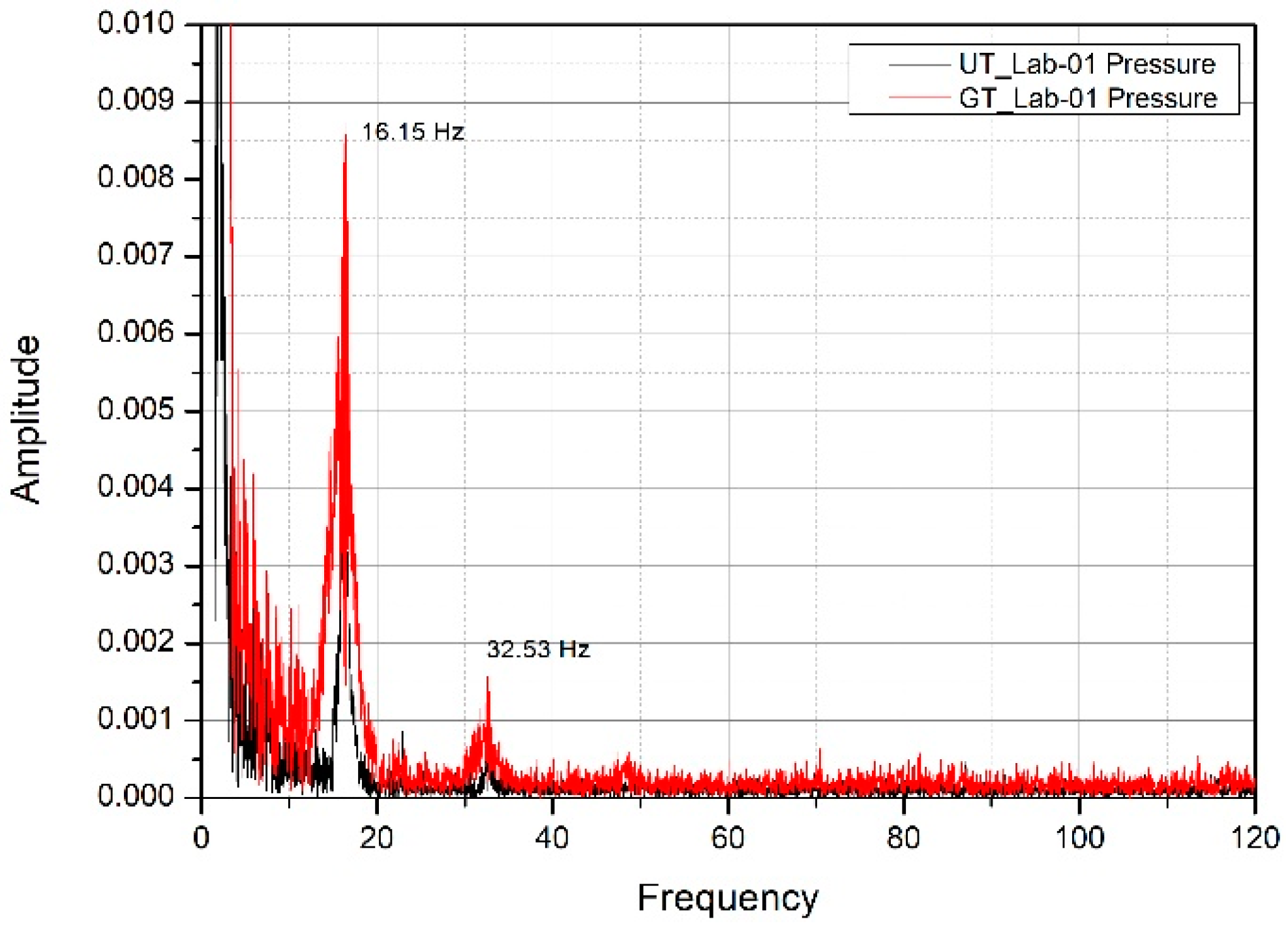
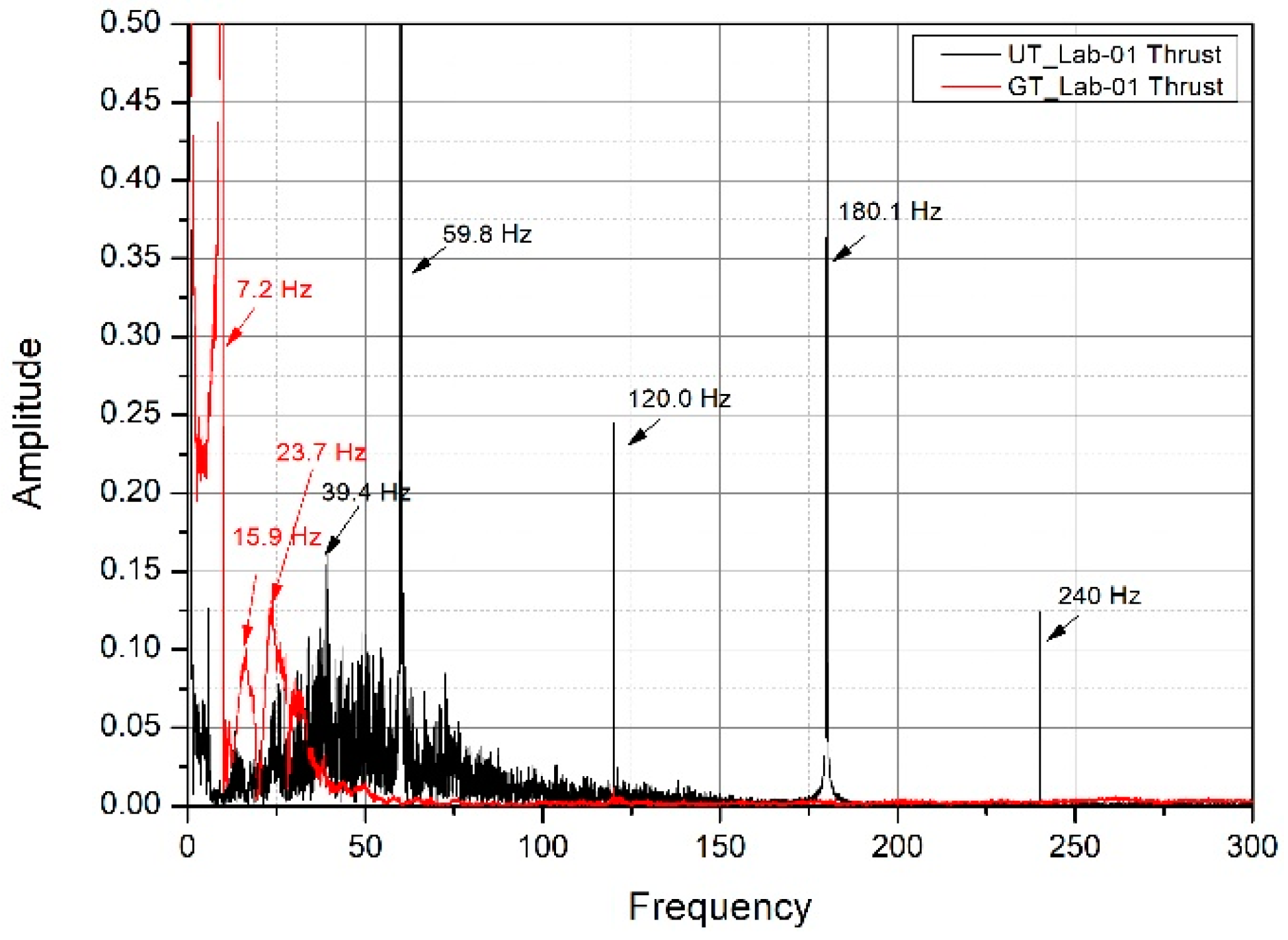
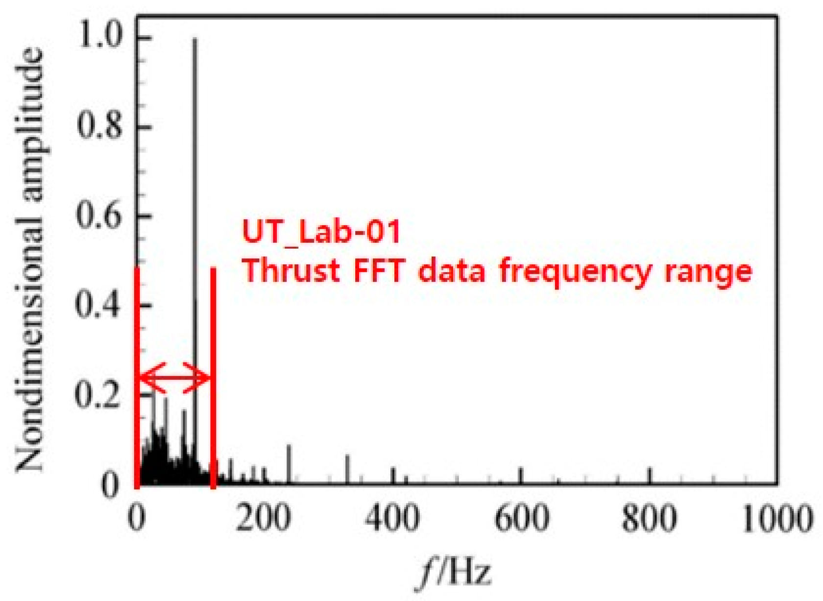
3.2. Thrust Oscillation in Underwater Environment

Extensive works [1,2,25,26,27,28,29,30,31] have reported that the gaseous jet injected into water results in complicated flow structures due mainly to the high water-to-gas density ratio leading to an extremely unsteady and turbulent multiphasic environment. In addition, the intermittent pulses of back pressure and nozzle exit pressure make the prediction and measurement of the flow structures extremely challenging either by computational fluid dynamics or experiments. From the literature [1,2], the nozzle exit environment can be categorized as expansion, bulge, necking/breaking, and back-attack depending on the formation and dissipation of the gas bag at the rear of the nozzle. In order to check and validate the gas bag formation encountered in this study, snapshots of exiting gaseous jets as well as Fast Fourier Transform (FFT) analysis of chamber pressure and of thrust were performed. Figure 15a,b shows the snapshots of the flow structure at the onset of jet exhaust into the water where the aforementioned four categorized phenomena can be depicted. The three snapshots of Figure 15b show the presence of necking/breaking and back-attack phenomena in which a high pressurized gas bag situated just downstream of the necking region is clearly seen. Following Tang et al. [1,2], it is believed that the oscillating back pressure can result in oscillating thrust. Accordingly, this fact may have triggered the thrust vibration observed in Figure 12d. It should be pointed out that the back-pressure variation of an underwater medium does not affect the chamber pressure for the case of the maximum supply oxidizer flow rate, i.e., with a choked nozzle throat. At the contrary, the chamber pressure can interact with the gas bag (filled with hot gas) downstream of the nozzle for the case of low oxidizer flow rate, i.e., with non-choking condition. To clarify this, FFT analyses were performed with the data from post-chamber pressure (Figure 16) and from thrust data (Figure 17). From the comparison shown in Figure 16, one can observe that the chamber pressure FFTs of the ground and underwater firing tests were nearly the same for both environments. Thus, one can confirm that the underwater test was conducted well within the choked condition. The observed frequency band of 18 Hz and 33 Hz was the signal noise frequency. Meanwhile, the thrust FFTs analyses of GT_lab-01 and UT_lab-01, shown in Figure 17, behaved differently as a consequence of gas bag presence in the water. Comparing the UT_Lab-01 spectrum shown in Figure 17 and Figure 18 of Tang et al. [1,2], one can remark that the amplitude observed in the frequency bandwidth of 0–100 Hz of this study nearly matched the one observed by Tang et al.

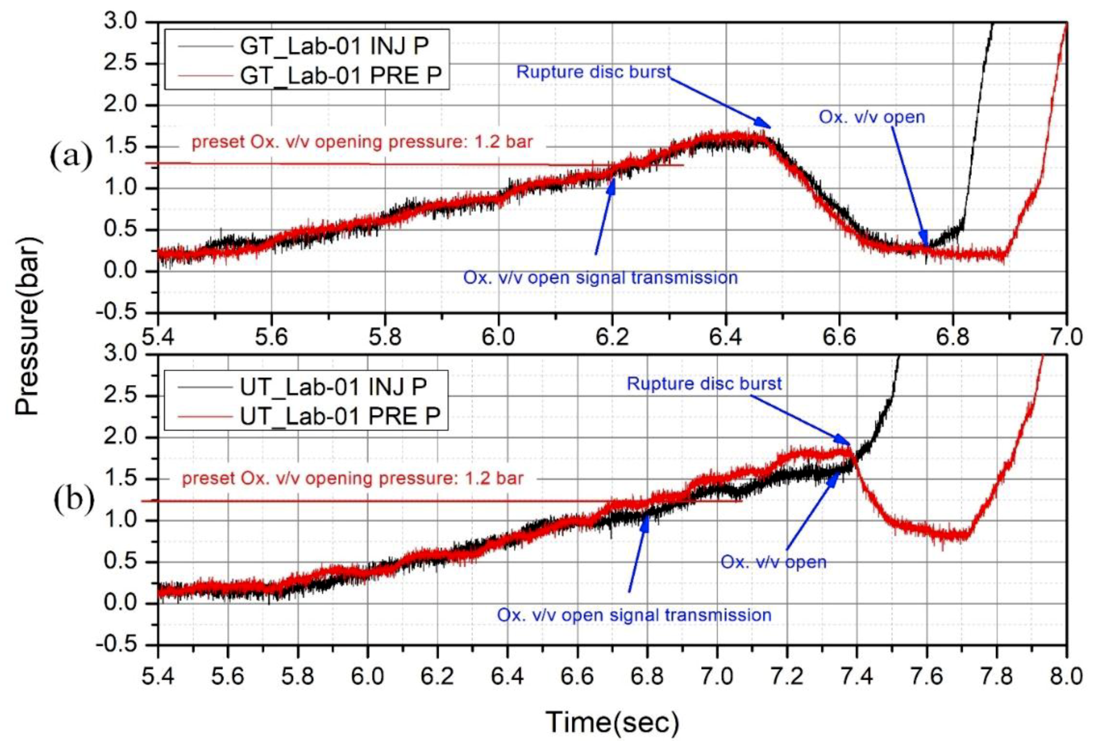
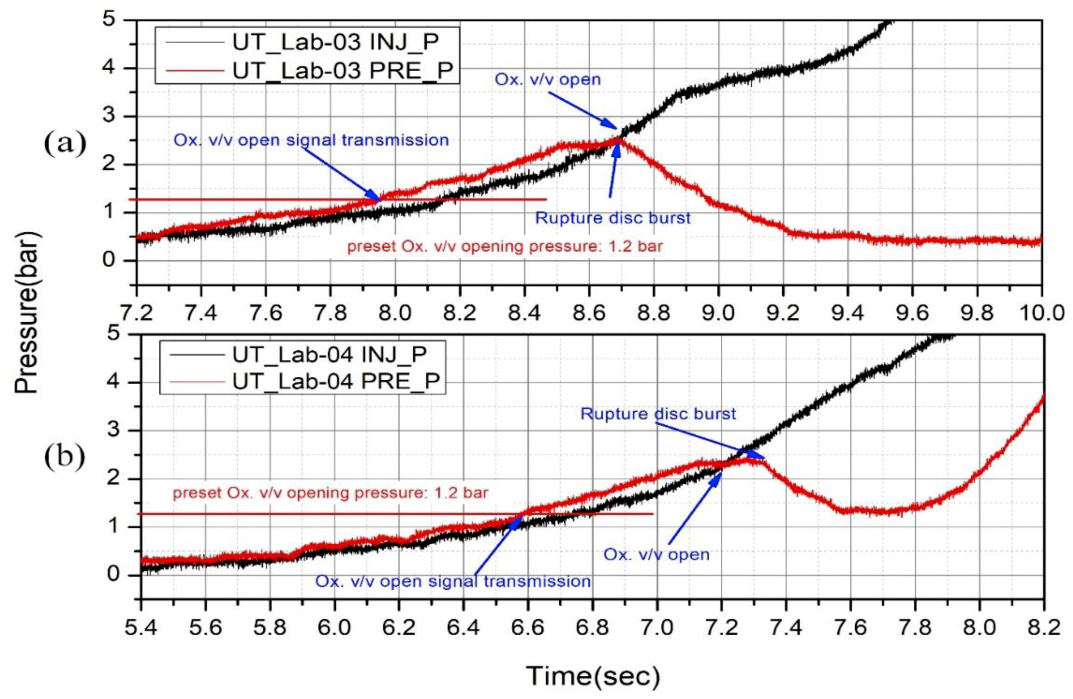
3.3. Ignition Characteristics

For a rocket motor submerged in the water, a dry environment of the combustion chamber is necessary especially for pyrotechnic ignition. The rupture disc is used to prevent the eventual intrusion of water and to keep the environment in the chamber dry, at least during the initial stage of ignition. The pyrotechnic ignition characteristics, with a rupture disc bursting at 2 bar for ground and underwater environments, are shown in Figure 19a,b, respectively. These two tests were conducted under identical experimental conditions (i.e., with the same rupture disc bursting pressure, the same “preset Ox. v/v opening pressure”, and the same amount of igniter).
As cited in Section 2.5, when the growing pre-chamber pressure attains the “preset Ox. v/v opening pressure”, the main oxidizer valve opening signal is triggered (signal on), and the igniter power is turned off simultaneously. The “preset Ox. v/v opening pressure” was preset to 1.2 bar due to a delay time (0.5–0.7 s) existing between the power signal “on” and the real valve opening moment. The rupture disc bursting pressure being set to 2 bar (gauge), the valve opening command was signaled on earlier to compensate this delay time. The optimal condition would be the exact moment when the oxidizer valve opens at the bursting event of the rupture disc. In order to find out the valve opening delay time after the command signal, numerous ignition tests were performed. It was found that a preset gauge pressure of 1.2 bar for the “preset Ox. v/v opening pressure” was the best preset value to resolve this delay. Since then, the “Identifier” number was given, e.g., UT_Lab-01.
Figure 19 and Figure 20 show the moment of signal transmission time, rupture disc bursting time, and oxidizer valve opening time for a clearer observation of the ignition sequence. It can be seen that after the rupture disc burst, the chamber pressure started to decrease toward atmospheric pressure followed later by the opening of the oxidizer valve that triggered the combustion leading to an abrupt pressure rise. It was observed that water intrusion was prevented during the ignition stage of the underwater tests. Figure 19a,b also shows early bursting events (below 2 bar) prior to the expected preset rupture disc bursting pressure. It seems that this was a consequence of the direct exposure of high temperature gases to the plate of the rupture disc, which resided in the small internal volume of the lab-scale motor.
When the minimum ignitable oxidizer mass flow rate was supplied to the combustion chamber, the pressure rise occurred very slowly with respect to the full throttle test case and there may have been a possibility of extinguishment due to water intrusion. In order to find out the safe operating condition for the minimum achievable and ignitable oxidizer mass flow rate, the amount of KNSB propellant as well as the rupture disc bursting pressure were varied and investigated (cf. Table 4). Figure 20a,b shows the case of the oxidizer valve angle of 54 degrees (UT_lab-03) and of 56 degrees (UT_lab-04), respectively. These correspond to 16.3% and 23.7% of the maximum (UT_Lab-01) oxidizer mass flow rate, respectively, where the minimum chamber pressure could be maintained at a gauge pressure of 0.5 bar and 1.2 bar, respectively. These conditions were achieved by increasing the amount of KNSB to 60 g.

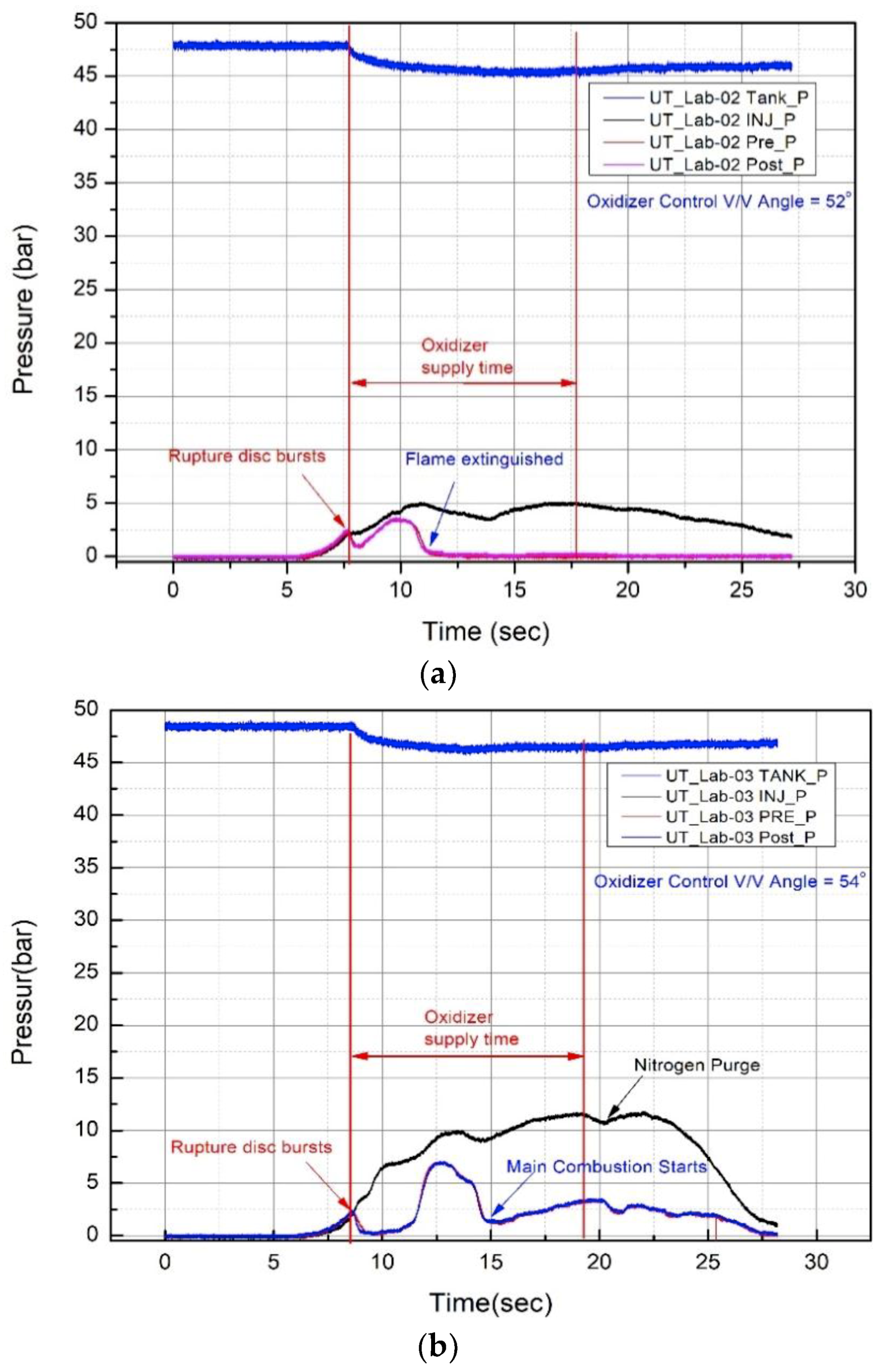
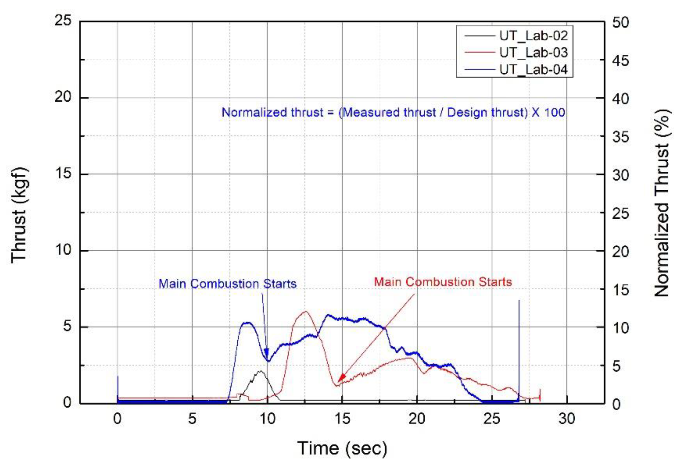
3.4. Motor Idling Condition in Underwater Environment

The sudden acceleration in the start-up stage is dangerous since it can disrupt the balance of the marine vehicles. Thus, finding idling conditions for the soft-start is crucial for stable operation. Experiments were carried out to find the optimum valve angle that can sustain the minimum thrust level. Figure 21a–c shows the results of experiments performed in the water where the valve angles were set to 52 degrees, 54 degrees, and 56 degrees, representing around 11.1%, 16.3% and 23.7% of the full throttle oxidizer supply, respectively. For all tests, the oxidizer tank pressure was initially set to 48 bar intentionally to retain the exact initial conditions of Figure 12c, i.e., the full throttle case. For all three Figures, one can clearly see that a bump in pre-chamber pressure trace was observed following the “rupture disc burst” event. This bump represents the pressure build-up section where the main oxidizer started to deliver fresh oxidizer to the combustion chamber mixed with KNSB propellant, which was still continuously burning. Looking to the case of valve angle 52 degrees (Figure 21a), it was confirmed that 11.1% of maximum flow rate was not enough to trigger any pressure rise, since the oxidizer mass flux was too low to sustain the main combustion in the chamber. Thus, the flame extinguished due to the extremely low oxidizer-to-fuel (O/F) ratio. However, three pressure build-up sections are depicted in Figure 21b,c (16.3% and 23.7% of the maximum flow rate, respectively) where the combustion was sustained, representing the motor idle case. The first pressure build-up section was due to KNSB propellant burning before the “rupture disc burst” event, while the second pressure build-up section that lies on the bump was due to the mixture of supplied fresh main oxidizer with the still burning KNSB as cited earlier. Finally, the third pressure build-up section was purely caused by the main combustion of N2O/HDPE in which the low slopes shown in Figure 21b,c resulted from the low oxidizer supply of 54 degrees and 56 degrees valve angles, respectively. It is worthwhile to note that the ignition delay after the second pressure build-up was decreased for augmented oxidizer mass flow. The ignition delays for the 54 degrees and 56 degrees cases were approximately 5 s and 2.3 s, respectively, while for the final combustion chamber pressure, it attained up to 3 bar and 7.5 bar, respectively. Meanwhile, Figure 22 shows the thrust and normalized thrust curve for underwater idling conditions. Due to the existing “bump” in the early operating stage and the self-pressurizing N2O blow down nature, fluctuations of instantaneous thrust were inevitable. For a clearer quantitative observation, we displayed the normalized thrust in percent with a double Y-axis. The thrust delivered from the main combustion of N2O/HDPE starting at 14.5 s (UT_Lab-03) and the one starting at 10 s (UT_Lab-04) each reached 6% and 12% of the maximum thrust, respectively.

4. Conclusions

In this study, attempts at hybrid rocket motor hot-firing tests were conducted in an underwater environment for marine application. A laboratory scale hybrid motor of 500 N class using liquid nitrous oxide and 5-port high density polyethylene (HDPE) fuel grain was used as a test-bed for the preliminary assessment of the underwater main propulsion or auxiliary boosting device. The use of a rupture disc for preventing the water intrusion, and the rupture disc blast timing both required a special precaution of the ignition signal command and sequence. From the FFT analysis of chamber pressure for the ground and underwater tests, no critical and notable difference was observed for the combustion chamber environment, while FFT analysis of underwater motor thrust revealed a vibration-prone environment, which was due in part to the wake structure downstream of the nozzle exit, a common fact encountered for a jet propulsive system compared to a screw propeller system.
Compared to the solid rocket counterpart, the hybrid rocket, with its throttleability, can offer a soft-start capability, which is essential for a marine vessel’s early stage of operation. The minimum power thrust, viewed as the idle test case with stable operation, was evaluated depending on the flow controlling optimum valve angle. It was found that 16.3% of the full throttle case sustained the minimum thrust level. Under full power, severe thrust oscillation was not observed in the underwater environment. These factors imply that the throttable hybrid rocket propulsion system can be a justifiable candidate for a short duration, high speed, marine boosting system or applied as a tactical system for naval application as an alternative to the solid propellant underwater rocket.

Author Contributions

Supervision, H.M.; conceptualization, H.M. and S.H.; investigation, S.H.; writing—review and editing, H.M. and S.H.; project management, Y.Y. and M.K.

Funding

This research was funded by the Agency for Defense Development (No. UE161021GD) and Advanced Research Center Program (NRF-2013R1A5A1073861).

Acknowledgments

This work was supported by the Defense Acquisition Program Administration and Agency for Defense Development (UE161021GD) Korea and supported by the Advanced Research Center Program (NRF-2013R1A5A1073861) through the National Research Foundation of Korea (NRF) grant funded by the Korea government (MSIP), contracted through the Advanced Space Propulsion Research Center at Seoul National University.

Conflicts of Interest

The authors declare no conflict of interest

Nomenclature

A p i Initial cross-section area(m2)
A p f Final cross-section area(m2)
G ¯ o Averaged oxidizer mass flux(kg·m–2·s–1)
L Fuel grain length(m)
Δ m Fuel mass difference(kg)
m ˙ ¯ o Averaged oxidizer mass flow rate(kg·s–1)
N Port number(-)
r ˙ ¯ Overall regression rate(m·s–1)
R p i Initial port radius(m)
R p f Final port radius(m)
t b Burning time(s)
ρ Fuel density(kg·m–3)

References

  1. Tang, J.N.; Wang, N.F.; Shyy, W. Flow structures of gaseous jets injected into water for underwater propulsion. Acta Mech. Sin. 2011, 27, 461–472. [Google Scholar] [CrossRef]
  2. Tang, J.; Tseng, C.C.; Wang, N.; Shyy, W. Flow structures of gaseous gets injected into water for underwater propulsion. In Proceedings of the 49th AIAA Aerospace Sciences Meeting including the New Horizons Forum and Aerospace Exposition, Orlando, FL, USA, 4–7 January 2011. [Google Scholar]
  3. Burke, A.E. Torpedoes and Their Impact on Naval Warfare; 0704-0188; Naval Undersea Warfare Center Division: Newport, RI, USA, 2017. [Google Scholar]
  4. Kirby, G. A history of the torpedo. J. R. Nav. Sci. Serv. 1972, 27, 30–105. [Google Scholar]
  5. Kirby, G. The Development of Rocket-Propelled Torpedoes. Available online: http://www.geoffkirby.co.uk/rocket-torpedoes.pdf (accessed on 26 January 2019).
  6. Garanin, I. The hydro-reacting marine solid fuel rocket engine. In Thermal to Mechanical Energy Conversion: Engines and Requirements-Volume II; United Nations Educational Scientific and Cultural Organization: Paris, France, 2009; Volume 8, pp. 201–240. [Google Scholar]
  7. Ng, K. Overview and future research directions of undersea weapon design & optimization. In Proceedings of the 9th AIAA/ISSMO Symposium on Multidisciplinary Analysis and Optimization, Atlanta, GA, USA, 4–6 September 2002. [Google Scholar]
  8. Han, S.J.; Moon, K.H.; Ko, S.H.; Kim, J.K.; Moon, H.J.; You, Y.J.; Kwon, M.C. Feasibility study and demonstration of an underwater lab-scale hybrid rocket propulsion. In Proceedings of the 53rd AIAA/SAE/ASEE Joint Propulsion Conference, Atlanta, GA, USA, 10–12 July 2017. [Google Scholar]
  9. Hwang, H.S.; Kim, H.S.; You, Y.J. Analysis on initial stability test results of underwater vehicle using the HR propulsion system. In Proceedings of the Korean Society of Propulsion Engineers, Jeju, Korea, 31 May–2 June 2017. [Google Scholar]
  10. Woo, K.J.; Min, M.K.; Lee, J.H.; Choo, B.K.; Lee, S.H.; Kim, G.M.; Kim, H.J.; Kim, J.M.; Hwang, H.S.; You, Y.J. A Study of hybrid rocket for underwater operation. In Proceedings of the Korean Society of Propulsion Engineers, Jeju, Korea, 31 May–2 June 2017. [Google Scholar]
  11. Han, S.J.; Moon, K.H.; Ko, S.H.; Kim, J.K.; You, Y.J.; Kwon, M.C.; Moon, H.J. Ignition characteristics of hybrid underwater propulsion system with rupture disc. In Proceedings of the Korean Society of Propulsion Engineers, Pusan, Korea, 22–24 November 2016. [Google Scholar]
  12. Kim, S.J.; Kim, H.C.; Kim, K.H.; Park, Y.H.; Park, S.J.; Lee, D.G.; Kim, J.K.; Moon, H.J.; You, Y.J.; Kwon, M.C. Underwater combustion test using lab-scale hybrid rocket motor. In Proceedings of the Korean Society of Propulsion Engineers, Jeju, Korea, 25–27 May 2016. [Google Scholar]
  13. Juliet-Marine-Brochure-1. Available online: http://www.julietmarine.com/pdfs/Juliet-Marine-Brochure-1.pdf (accessed on 26 January 2019).
  14. Sakurai, T.; Tomizawa, T. Applicability of a LOx vaporization preburner for swirling-flow hybrid rocket engines. In Proceedings of the 51st AIAA/SAE/ASEE Joint Propulsion Conference, Orlando, FL, USA, 27–29 July 2015. [Google Scholar]
  15. Calabro, M. LOx/HTPB/AlH3 hybrid propulsion for launch vehicle boosters. In Proceedings of the 40th AIAA/ASME/SAE/ASEE Joint Propulsion Conference and Exhibit, Fort Lauderdale, FL, USA, 11–14 July 2004. [Google Scholar]
  16. Rice, E.; Gramer, D. Methane and methane/aluminum cryogenic hybrid rocket engines for Mars ISRU propulsion. In Proceedings of the 38th Aerospace Sciences Meeting and Exhibit, Reno, NV, USA, 10–13 January 2000. [Google Scholar]
  17. Risha, G.; Boyer, E.; Wehrman, R.; Evans, B.; Kuo, K. Nano-sized aluminum and boron-based solid fuel characterization in a hybrid rocket engine. In Proceedings of the 39th AIAA/ASME/SAE/ASEE Joint Propulsion Conference and Exhibit, Huntsville, AL, USA, 20–23 July 2003. [Google Scholar]
  18. Marothiya, G.; Ramakrishna, P. Utilization of mechanically activated aluminum in hybrid rockets. J. Propuls. Power 2018, 34, 1206–1213. [Google Scholar] [CrossRef]
  19. Paccagnella, E.; Barato, F.; Pavarin, D.; Karabeyoğlu, A. Scaling parameters of swirling oxidizer injection in hybrid rocket motors. J. Propuls. Power 2017, 33, 1378–1394. [Google Scholar] [CrossRef]
  20. Arena, Z.; Athougies, A.; Rodulfo, A.; DeTurris, D. Swirl injection hybrid rocket motor design and testing. In Proceedings of the 47th AIAA/ASME/SAE/ASEE Joint Propulsion Conference & Exhibit, San Diego, CA, USA, 31 July–3 August 2011. [Google Scholar]
  21. Kim, S.J.; Lee, J.P.; Moon, H.J.; Kim, J.K.; Sung, H.G.; Kwon, O.C. Regression characteristics of the cylindrical multiport grain in hybrid rockets. J. Propuls. Power 2013, 29, 573–581. [Google Scholar] [CrossRef]
  22. Kim, G.H. A Study on Combustion Characteristic of the Cylindrical Multi-Port Grain for Hybrid Rocket Motor Using PE/N2O. Master’s Thesis, Korea Aerospace University, Goyang, Korea, 20 January 2010. [Google Scholar]
  23. Kim, S.J.; Kim, J.K.; Moon, H.J.; Sung, H.G.; Lee, J.P.; Kim, G.H.; Cho, J.T.; Park, S.H. Combustion characteristics of the cylindrical multi-port grain for hybrid rocket motor. In Proceedings of the 45th AIAA/ASME/SAE/ASEE Joint Propulsion Conference & Exhibit, Denver, CO, USA, 2–5 August 2009. [Google Scholar]
  24. Kim, G.H.; Kim, S.J.; Lee, J.P.; Cho, J.T.; Moon, H.J.; Sung, H.G.; Kim, J.K. A study on merge effect in the multi-port fuel grain of hybrid rockets. In Proceedings of the 2009 Asia-Pacific International Symposium on Aerospace Technology, Gifu, Japan, 4–6 November 2009. [Google Scholar]
  25. Chen, K.; Richter, H. Instability analysis of the transition from bubbling to jetting in a gas injected into a liquid. Int. J. Multiph. Flow 1997, 23, 699–712. [Google Scholar] [CrossRef]
  26. Dai, Z.; Wang, B.; Qi, L.; Shi, H. Experimental study on hydrodynamic behaviors of high-speed gas jets in still water. Acta Mech. Sin. 2006, 22, 443–448. [Google Scholar] [CrossRef] [Green Version]
  27. Linck, M.B.; Gupta, A.K.; Yu, K.H. Submerged combustion and two-phase exhaust jet instabilities. J. Propuls. Power 2009, 25, 522–532. [Google Scholar] [CrossRef]
  28. Loth, E.; Faeth, G.M. Structure of plane under expanded air jets into water. J. AIChE 1990, 36, 818–826. [Google Scholar] [CrossRef]
  29. Shi, H.; Wang, B.; Dai, Z. Research on the mechanics of underwater supersonic gas jets. Sci. China Phys. Mech. 2010, 53, 527–535. [Google Scholar] [CrossRef] [Green Version]
  30. Shi, H.H.; Guo, Q.; Wang, C.; Dong, R.L.; Zhang, L.T.; Jia, H.X.; Wang, X.G.; Wang, B.Y. Oscillation flow induced by underwater supersonic gas jets. Shock Waves 2010, 20, 347–352. [Google Scholar] [CrossRef] [Green Version]
  31. Weiland, C.; Vlachos, P.P. Round gas jets submerged in water. Int. J. Multiph. Flow 2013, 48, 46–57. [Google Scholar] [CrossRef]
Figure 1. (a) CAMROSE dynamic test vehicle c.1954 [5]; (b) Ghost (Juliet Marine system) [13].
Aerospace 06 00028 g001
Figure 2. Schematic of experimental setup for underwater hot-firing test.
Aerospace 06 00028 g002
Figure 3. (a) Cross-sectional view of lab-scale motor; (b) lab-scale hybrid rocket motor mounted in the water tank.
Aerospace 06 00028 g003
Figure 4. Rupture disc (provided by FDC Co. Ltd. Gimhae, Korea), (a) bursting pressure set to 2 bar gauge; (b) bursting pressure set to 3 bar gauge.
Aerospace 06 00028 g004
Figure 5. Oxidizer run tank and mass flow measurement.
Aerospace 06 00028 g005
Figure 6. Fuel grain configuration, (a) front view; (b) side view.
Aerospace 06 00028 g006
Figure 7. Fuel grain after combustion, (a) front view; (b) rear view.
Aerospace 06 00028 g007
Figure 8. N2O/HDPE multi-port regression rates correlations [22].
Aerospace 06 00028 g008
Figure 9. KNSB igniter mounted in pre-chamber.
Aerospace 06 00028 g009
Figure 10. Water tank and vertical transfer system of hybrid motor.
Aerospace 06 00028 g010
Figure 11. Pressure signal triggering loop.
Aerospace 06 00028 g011
Figure 12. (a) Pressure curve of ground test (GT_Lab-01); (b) thrust curve of ground test (GT_Lab-01); (c) pressure curve of underwater test (UT_Lab-01); (d) thrust curve of underwater test (UT_Lab-01).
Aerospace 06 00028 g012
Figure 13. Snapshot of ground hot-firing test.
Aerospace 06 00028 g013
Figure 14. Snapshot of underwater hot-firing test.
Aerospace 06 00028 g014
Figure 15. Snapshots of flow structures during underwater hot-firing test, (a) expansion and bulging process; (b) necking/breaking and back-attack process.
Aerospace 06 00028 g015
Figure 16. Fast Fourier transform (FFT) results of post-chamber pressure for ground and underwater test.
Aerospace 06 00028 g016
Figure 17. FFT results of thrust data for ground and underwater test.
Aerospace 06 00028 g017
Figure 18. FFT results of back pressure oscillation from Tang et al. [1,2].
Aerospace 06 00028 g018
Figure 19. Ignition curve, (a) GT_Lab-01 w/rupture disc 2 bar; (b) UT_Lab-01 w/rupture disc 2 bar.
Aerospace 06 00028 g019
Figure 20. Ignition curve, (a) UT_Lab-03 w/rupture disc 3 bar; (b) UT_Lab-04 w/rupture disc 3 bar.
Aerospace 06 00028 g020
Figure 21. Pressure curves at idling condition, (a) UT_Lab-02 (52 degrees oxidizer control v/v angle); (b) UT_Lab-03 (54 degrees oxidizer control v/v angle); (c) UT_Lab-04 (56 degrees oxidizer control v/v angle).
Aerospace 06 00028 g021aAerospace 06 00028 g021b
Figure 22. Thrust and normalized thrust curves for underwater idling conditions.
Aerospace 06 00028 g022
Table 1. Specifications of the experimental conditions for underwater firing test.
HeadingHeading
Design thrust (kgf)50
OxidizerLiquid nitrous oxide
Solid fuelHigh density polyethylene (HDPE)
IgniterPotassium nitrate/sorbitol (KNSB) propellant
Fuel density (kg/m3)950
Burning time (s)10
Oxidizer mass flow rate range (g/s)15–134
Initial port diameter (mm)10
Grain outer diameter (mm)104.5
Port number5
Grain length (mm)146
Table 2. Specification of oxidizer mass flow control valve.
ModelSupplier (Country)Orifice Diameter (mm)Temperature Rating (°C)Pressure Rating (bar)
VL82A-D-4T-SDK-lok (KOR)3.2−54 to 65172
Table 3. Specification of oxidizer mass flow control motor.
ModelSupplier (Country)Motor TypeMotionMax. Resolution (deg/pulse)Min. Resolution (deg/pulse)
MDrive 23 PlusSchneider Electric (USA)Stepping MotorCW/CCW1.80.007
Table 4. Ground and underwater hot-firing test cases.
IdentifierGT_Lab-01UT_Lab-01UT_Lab-02UT_Lab-03UT_Lab-04
Test environmentGroundUnderwater
Oxidizer control valve angle (deg)w/o v/vw/o v/v525456
Average oxidizer mass flow rate (g/s)121.1134.615.022.032.0
Average fuel mass flow rate (g/s)21.221.8-8.510.5
Average oxidizer-to-fuel (O/F) ratio5.76.2-2.63.0
Rupture disc bursting pressure (bar)22333
Preset Ox. v/v opening pressure (bar)1.21.21.21.21.2
Amount of pyrotechnic igniter (g)3030606060

