Challenges of Fully-Coupled High-Fidelity Ditching Simulations
Abstract
1. Introduction
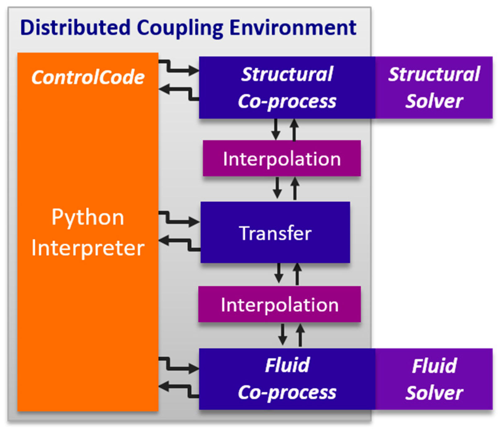
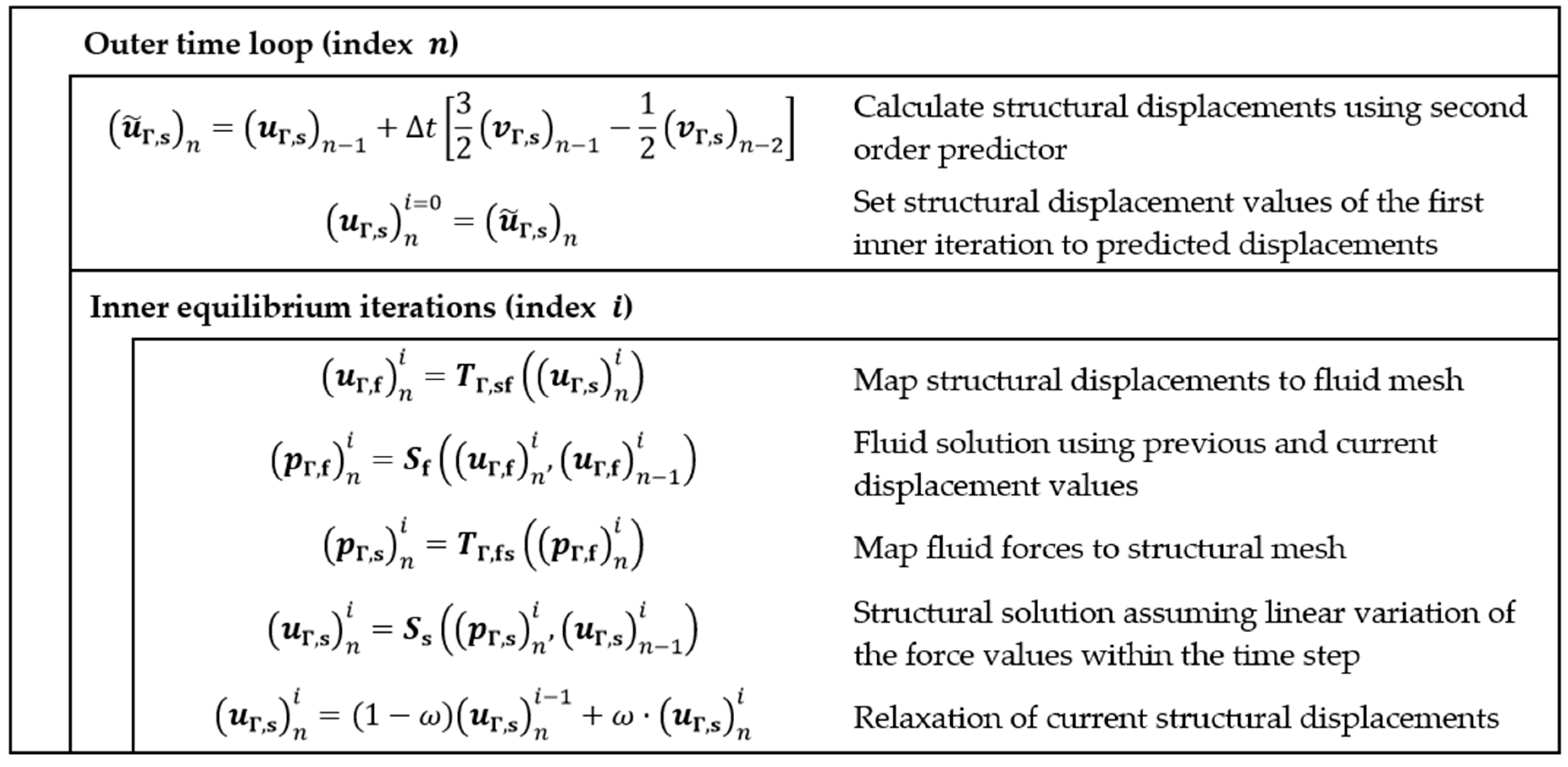
2. Numerical Simulation Framework
3. Results and Discussion
3.1. Validation Studies
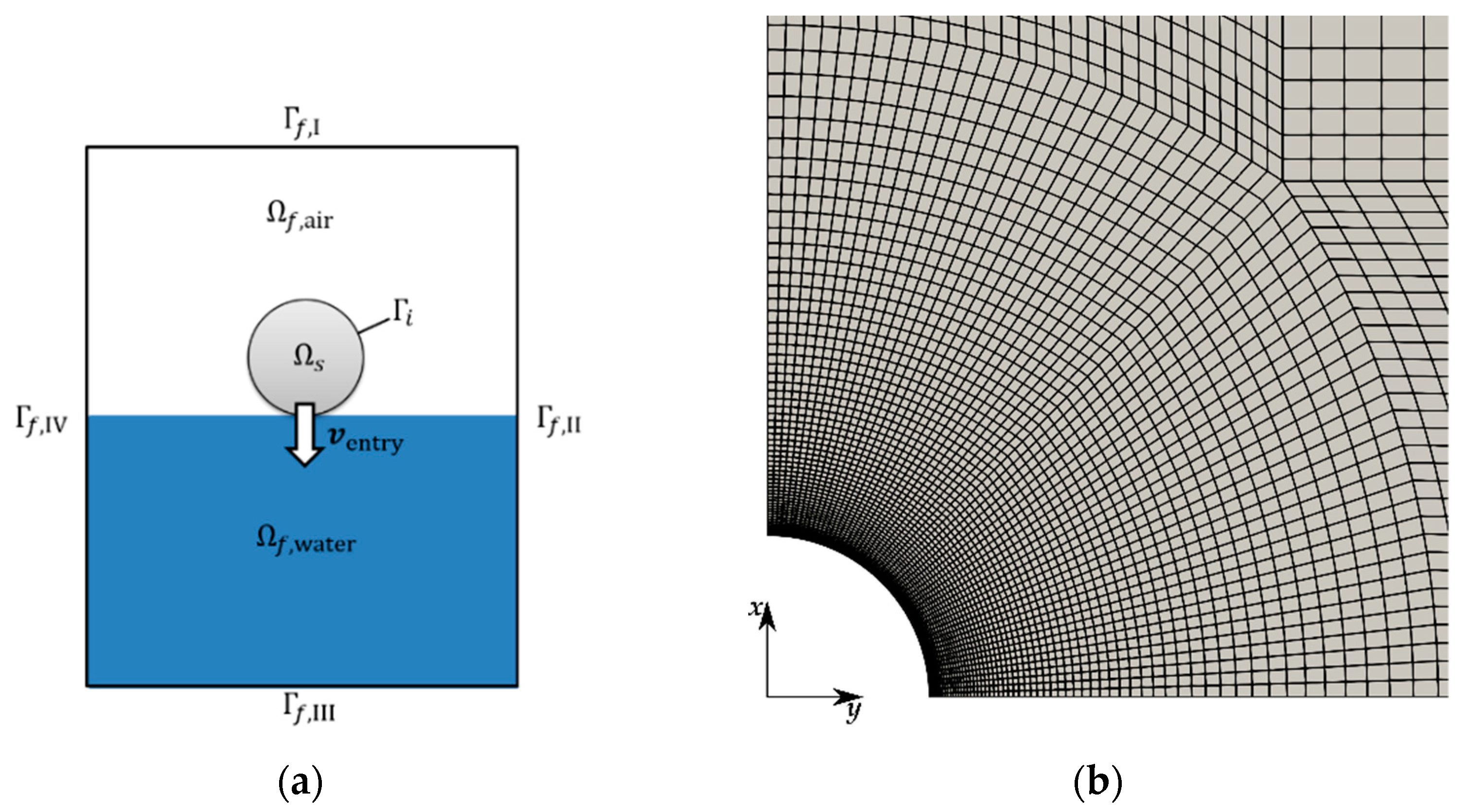
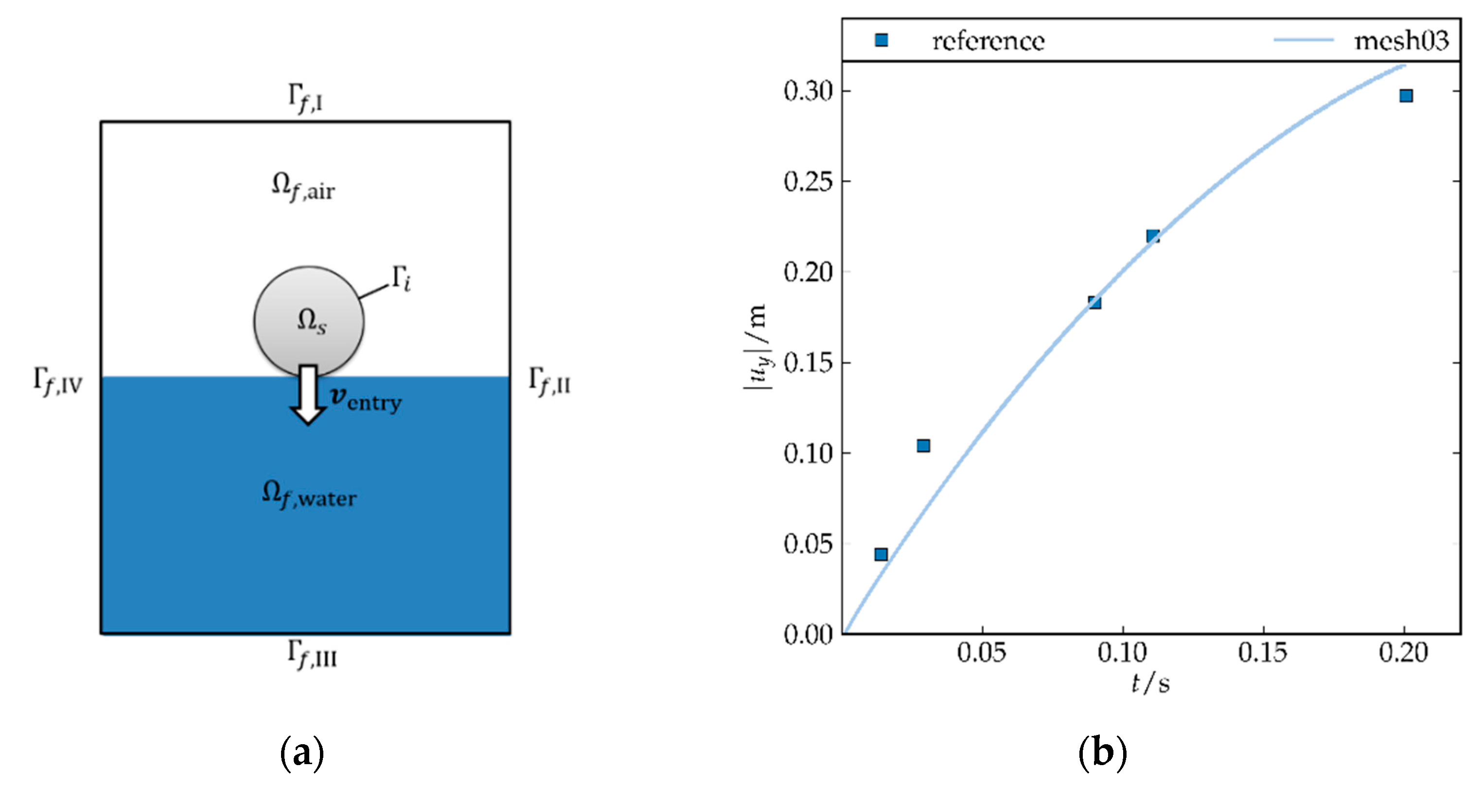
3.1.1. Drop Test of Rigid Cylinder
3.1.2. Drop Test of Deformable Cylinder
3.2. Structural Model
3.2.1. Global FE-Model
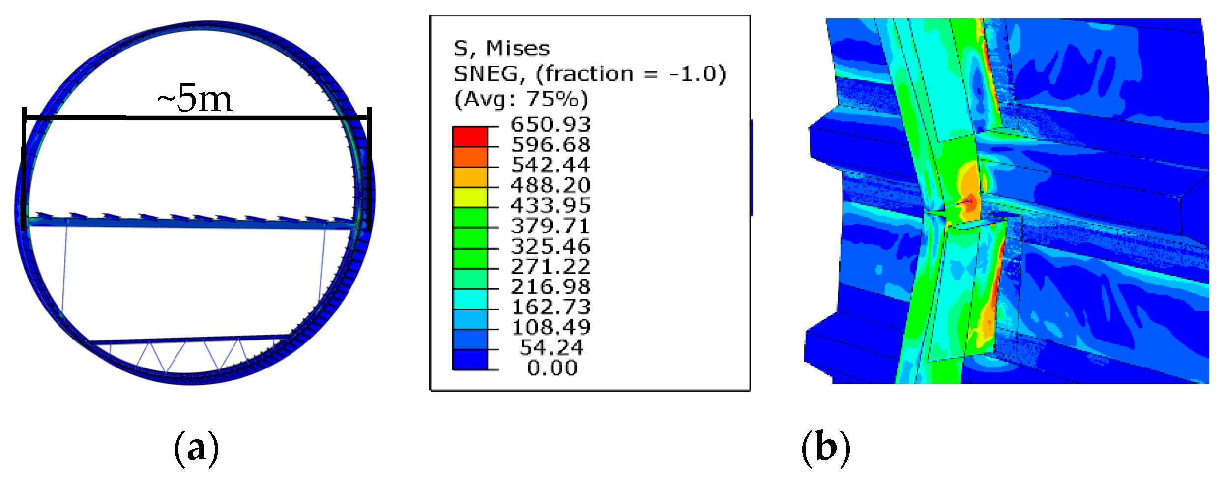
3.2.2. Fuselage Crash Simulations
3.2.3. Multiscale Model for Ditching Simulation
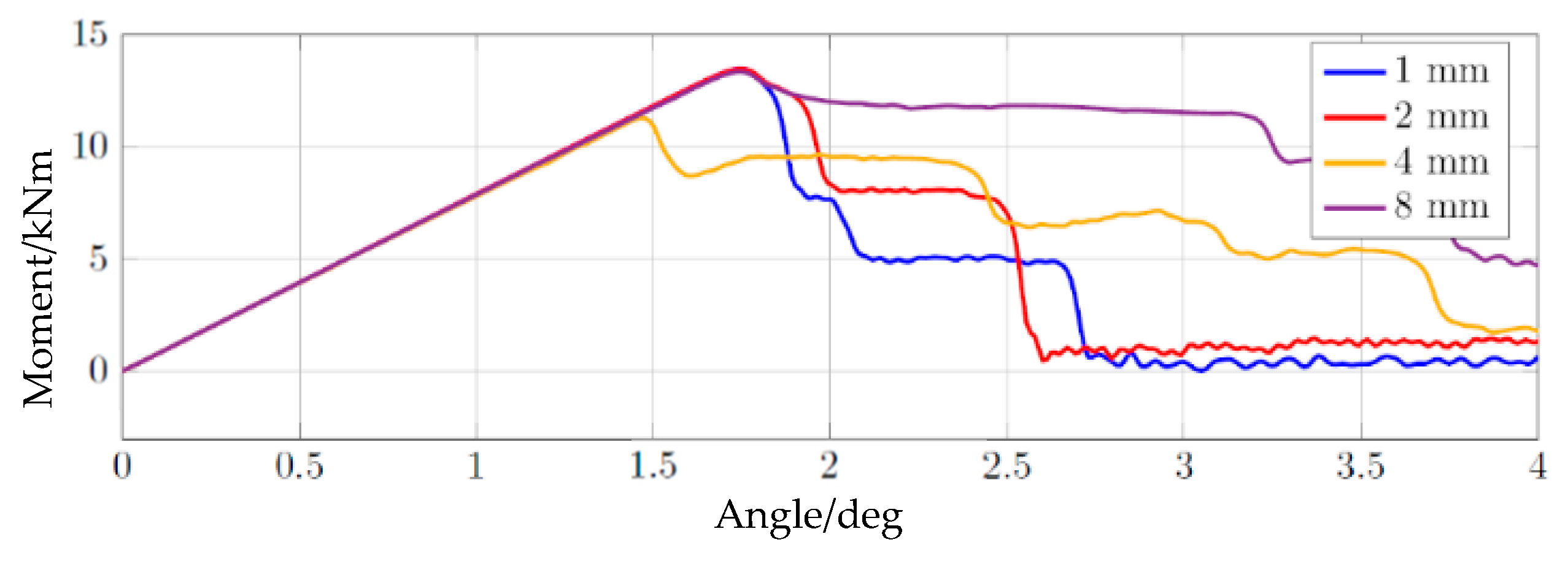
3.2.4. Modelling Damage
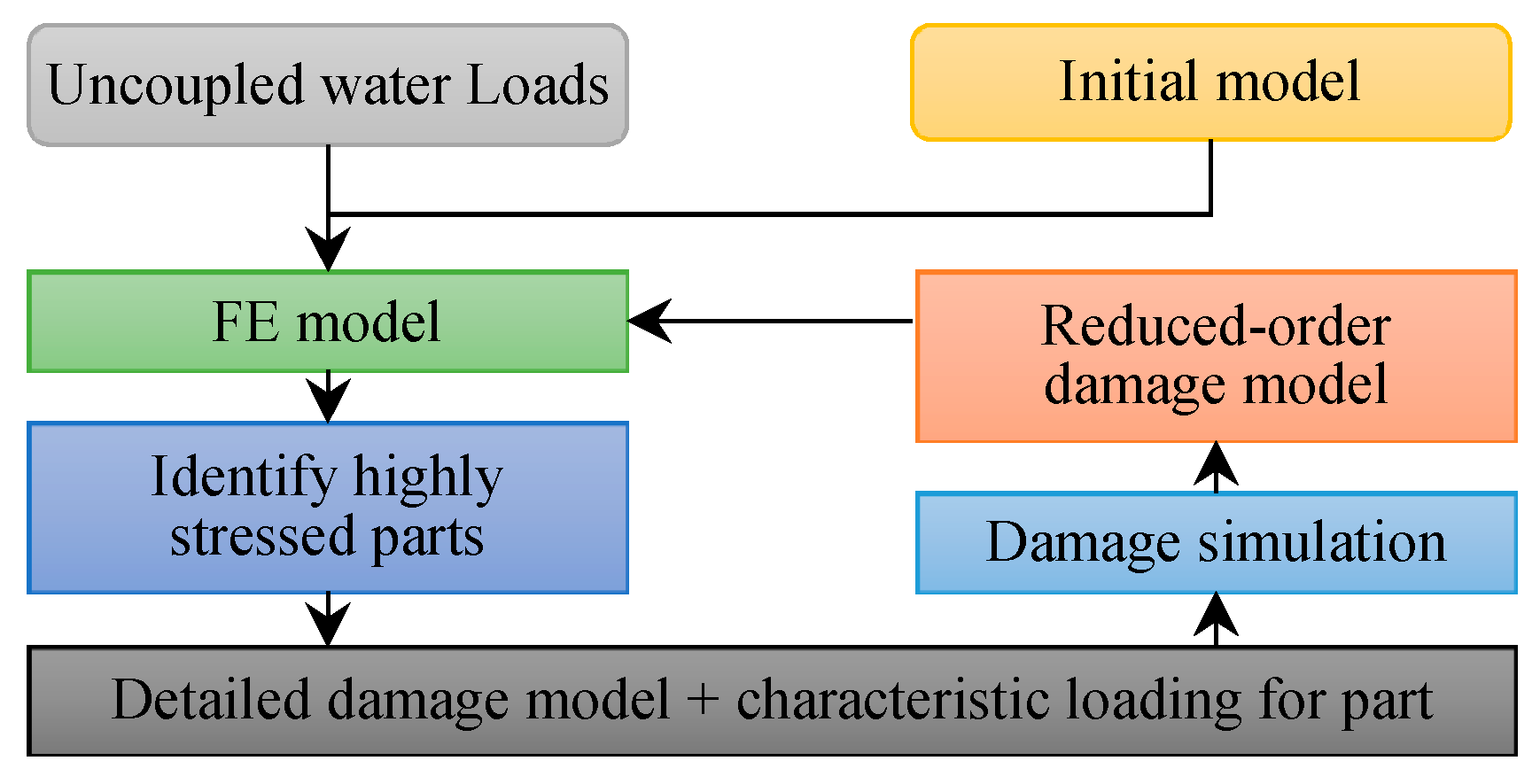
3.2.5. Creating the Multiscale Model
4. Conclusions and Outlook
Author Contributions
Funding
Acknowledgments
Conflicts of Interest
References
- European Aviation Safety Agency. Certification Specifications and Acceptable Means of Compliance for Large Aeroplanes CS-25, Book 1—Certification Specifications, Subpart C, Section CS 25.801—Ditching: CS 25.801. Amendment 22. Available online: https://www.easa.europa.eu/sites/default/files/dfu/CS-25%20Amendment%2022.pdf (accessed on 11 January 2019).
- Federal Aviation Administration (FAA), Department of Transportation. Code of Federal Regulations, Title 14, Chapter I, Subchapter C, Part 25, Subpart D, Section 25.801—Ditching: 14 CFR 25.801. Available online: https://www.law.cornell.edu/cfr/text/14/25.801 (accessed on 11 January 2019).
- Siemann, M.H.; Langrand, B. Coupled fluid-structure computational methods for aircraft ditching simulations: Comparison of ALE-FE and SPH-FE approaches. Comput. Struct. 2017, 188, 95–108. [Google Scholar] [CrossRef]
- Pentecôte, N.; Vigliotti, A. Crashworthiness of helicopters on water: Test and simulation of a full-scale WG30 impacting on water. Int. J. Crashworth. 2003, 8, 559–572. [Google Scholar] [CrossRef]
- Wernsdorfer, T.; Keller, K.; Climent, H. CN-235-300M Deepwater—Subscale Model, Ditching and Floatation Tests Plan, Issue A; EASA-CASA: Madrid, Spain, 2003. [Google Scholar]
- Climent, H.; Benitez, L.; Rosich, F.; Rueda, F.; Pentecote, N. Aircraft Ditching Numerical Simulation. In Proceedings of the 25th International Congress of the Aeronautical Sciences, Hamburg, Germany, 3–8 September 2006. [Google Scholar]
- Keller, A.P. Cavitation Scale Effects—Empirically Found Relations and the Correlation of Cavitation Number and Hydrodynamic Coefficients. In Proceedings of the CAV 2001: Fourth International Symposium on Cavitation, California Institute of Technology, Pasadena, CA, USA, 20–23 June 2001. [Google Scholar]
- Lindenau, O.; Busch, C.; Streckwall, H.; Bensch, L.; Rung, T. Validation of a transport aircraft ditching simulation tool. In Proceedings of the 6th International KRASH Users’ Seminar (IKUS6), Stuttgart, Germany, 15–17 June 2009. [Google Scholar]
- Halbout, S.; Vagnot, A.; Markmiller, J. Modelling of water impact during ditching event. Available online: https://dspace-erf.nlr.nl/xmlui/bitstream/handle/20.500.11881/3673/ERF2016_47_S.%20HALBOUT%20_P.pdf?sequence=1 (accessed on 11 January 2019).
- Anghileri, M.; Castelletti, L.-M.L.; Francesconi, E.; Milanese, A.; Pittofrati, M. Survey of numerical approaches to analyse the behavior of a composite skin panel during a water impact. Int. J. Impact Eng. 2014, 63, 43–51. [Google Scholar] [CrossRef]
- Bisagni, C.; Pigazzini, M.S. Modelling strategies for numerical simulation of aircraft ditching. Int. J. Crashworth. 2018, 23, 377–394. [Google Scholar] [CrossRef]
- Iafrati, A.; Grizzi, S.; Siemann, M.H.; Benítez Montañés, L. High-speed ditching of a flat plate: Experimental data and uncertainty assessment. J. Fluids Struct. 2015, 55, 501–525. [Google Scholar] [CrossRef]
- Waimer, M.; Kohlgrüber, D.; Hachenberg, D.; Voggenreiter, H. The Kinematics Model—A Numerical Method for the Development of a Crashworthy Composite Fuselage Design of Transport Aircraft. In Proceedings of the Sixth Triennial International Aircraft Fire and Cabin Safety Research Conference, Atlantic City, NJ, USA, 25–28 October 2010. [Google Scholar]
- Reinhard, M.; Korobkin, A.A.; Cooker, M.J. Water entry of a flat elastic plate at high horizontal speed. J. Fluid Mech. 2013, 724, 123–153. [Google Scholar] [CrossRef]
- Newman, J.M. Marine Hydrodynamics; MIT Press: Cambridge, MA, USA, 1977. [Google Scholar]
- Le Tallec, P.; Mouro, J. Fluid structure interaction with large structural displacements. Comput. Methods Appl. Mech. Eng. 2001, 190, 3039–3067. [Google Scholar] [CrossRef]
- Causin, P.; Gerbeau, J.F.; Nobile, F. Added-mass effect in the design of partitioned algorithms for fluid–structure problems. Comput. Methods Appl. Mech. Eng. 2005, 194, 4506–4527. [Google Scholar] [CrossRef]
- Förster, C.; Wall, W.A.; Ramm, E. Artificial added mass instabilities in sequential staggered coupling of nonlinear structures and incompressible viscous flows. Comput. Methods Appl. Mech. Eng. 2007, 196, 1278–1293. [Google Scholar] [CrossRef]
- Küttler, U.; Wall, W.A. Fixed-point fluid–structure interaction solvers with dynamic relaxation. Comput. Mech. 2008, 43, 61–72. [Google Scholar] [CrossRef]
- Küttler, U.; Gee, M.; Förster, C.; Comerford, A.; Wall, W.A. Coupling strategies for biomedical fluid–structure interaction problems. Int. J. Numer. Methods Biomech. Eng. 2010, 26, 305–321. [Google Scholar] [CrossRef]
- Ortiz, R.; Charles, J.L.; Sobry, J.F. Structural loading of a complete aircraft under realistic crash conditions: Generation of a load database for passenger safety and innovative design. In Proceedings of the 24th International Congress of the Aeronautical Sciences, Yokohama, Japan, 29 August–3 September 2004. [Google Scholar]
- Kohlgruber, D.; Vigliotti, A.; Weissberg, V.; Bartosch, H. Numerical simulation of a composite helicopter sub-floor structure subjected to water impact. In Proceedings of the 60th Annual Forum of the American Helicopter Society, Baltimore, MD, USA, 7–10 June 2004; pp. 7–10. [Google Scholar]
- Groenenboom, P.H.; Campbell, J.; Benítez Montañés, L.; Siemann, M.H. Innovative SPH methods for aircraft ditching. In Proceedings of the 11th WCCM/5th ECCM, Barcelona, Spain, 20–25 July 2014. [Google Scholar]
- Smith, A.G.; Warren, C.H.E.; Wright, D.F. Investigations of the Behaviour of Aircraft When Making a Forced Landing on Water (Ditching); Her Majesty’s Stationery Office: London, UK, 1957. [Google Scholar]
- Kowollik, D.; Tini, V.; Reese, S.; Haupt, M. 3D fluid-structure interaction analysis of a typical liquid rocket engine cycle based on a novel viscoplastic damage model. Int. J. Numer. Methods Eng. 2013, 94, 1165–1190. [Google Scholar] [CrossRef]
- Lindhorst, K.; Haupt, M.C.; Horst, P. Reduced-order modelling of non-linear, transient aerodynamics of the HIRENASD wing. Aeronaut. J. 2016, 120, 601–626. [Google Scholar] [CrossRef]
- Sommerwerk, K.; Haupt, M.C. Design analysis and sizing of a circulation controlled CFRP wing with Coandǎ flaps via CFD–CSM coupling. CEAS Aeronaut. J. 2014, 5, 95–108. [Google Scholar] [CrossRef]
- Haupt, M.; Niesner, R.; Unger, R.; Horst, P. Computational Aero-Structural Coupling for Hypersonic Applications. In Proceedings of the 9th AIAA/ASME Joint Thermophysics and Heat Transfer Conference, San Francisco, CA, USA, 5–8 June 2006; American Institute of Aeronautics and Astronautics: Reston, VA, USA, 2006; p. 95. [Google Scholar]
- Müller, M.; Haupt, M.; Horst, P. Socket-Based Coupling of OpenFOAM and Abaqus to Simulate Vertical Water Entry of Rigid and Deformable Structures. In Proceedings of the 6th ESI OpenFOAM User Conference 2018, Hamburg, Germany, 23–25 October 2018. [Google Scholar]
- Mok, D.P.; Wall, W.A.; Ramm, E. Accelerated iterative substructuring schemes for instationary fluid-structure interaction. Comput. Fluid Solid Mech. 2001, 2, 1325–1328. [Google Scholar]
- Greenhow, M.; Lin, W.M. Nonlinear-Free Surface Effects: Experiments and Theory; Massachusetts Institute of Technology Cambridge: Cambridge, MA, USA, 1983. [Google Scholar]
- Deshpande, S.S.; Anumolu, L.; Trujillo, M.F. Evaluating the performance of the two-phase flow solver interFoam. Comput. Sci. Discov. 2012, 5, 14016. [Google Scholar] [CrossRef]
- Roenby, J.; Bredmose, H.; Jasak, H. A computational method for sharp interface advection. R. Soc. Open Sci. 2016, 3, 160405. [Google Scholar] [CrossRef]
- Arai, M.; Miyauchi, T. Numerical Simulation of the Water Impact on Cylindrical Shells Considering Fluid-Structure Interaction. J. Soc. Nav. Archit. Jpn. 1997, 1997, 827–835. [Google Scholar] [CrossRef]
- Sun, H.; Faltinsen, O.M. Water impact of horizontal circular cylinders and cylindrical shells. Appl. Ocean Res. 2006, 28, 299–311. [Google Scholar] [CrossRef]
- Ionina, M.F.; Korobkin, A.A. Water Impact on Cylindrical Shell. In Proceedings of the 14th International Workshop on Water Waves and Floating Bodies, Port Huron, MI, USA, 11–14 April 1999. [Google Scholar]
- Wagner, H. Über Stoss-und Gleitvorgänge an der Oberfläche von Flüssigkeiten. Z. Angew. Math. Mech. 1932, 12, 193–235. [Google Scholar] [CrossRef]
- Weiß, L. Initial Design of Crashworthy Composite Structures. Ph.D. Thesis, Technischen Universität Carolo-Wilhelmina, Braunschweig, Germany, 2016. [Google Scholar]
- Byar, A. A Crashworthiness Study of a Boeing 737 Fuselage Section. Ph.D. Thesis, Drexel University, Philadelphia, PA, USA, 2003. [Google Scholar]
- Guidoboni, G.; Glowinski, R.; Cavallini, N.; Canic, S. Stable loosely-coupled-type algorithm for fluid–structure interaction in blood flow. J. Comput. Phys. 2009, 228, 6916–6937. [Google Scholar] [CrossRef]
- Li, L.; Henshaw, W.D.; Banks, J.W.; Schwendeman, D.W.; Main, A. A stable partitioned FSI algorithm for incompressible flow and deforming beams. J. Comput. Phys. 2016, 312, 272–306. [Google Scholar] [CrossRef]
- Badia, S.; Quaini, A.; Quarteroni, A. Modular vs. non-modular preconditioners for fluid–structure systems with large added-mass effect. Comput. Methods Appl. Mech. Eng. 2008, 197, 4216–4232. [Google Scholar] [CrossRef]
- Burman, E.; Fernández, M.A. Explicit strategies for incompressible fluid-structure interaction problems: Nitsche type mortaring versus Robin-Robin coupling. Int. J. Numer. Methods Eng. 2014, 97, 739–758. [Google Scholar] [CrossRef]
- Steger, J.L.; Dougherty, F.C.; Benek, J.A. A chimera grid scheme. [Multiple overset body-conforming mesh system for finite difference adaptation to complex aircraft configurations]. Advances in grid generation. In Proceedings of the Applied Mechanics, Bioengineering, and Fluids Engineering Conference, Houston, TX, USA, 20–22 June 1983; (A84-11576 02-64). American Society of Mechanical Engineers: New York, NY, USA, 1983; pp. 59–69. [Google Scholar]

| Boundary | Pressure | Velocity |
|---|---|---|
| Constant zero pressure | Outflow: zero gradient in normal direction | |
| Inflow: Robin condition based on flux in the patch-normal direction | ||
| Zero gradient in normal direction | Constant zero velocity |
| Parameters | Value |
|---|---|
| Outer cylinder diameter | |
| Shell thickness | |
| Entry velocity | |
| Shell density | |
| Young’s modulus | |
| Poisson’s ratio |
© 2019 by the authors. Licensee MDPI, Basel, Switzerland. This article is an open access article distributed under the terms and conditions of the Creative Commons Attribution (CC BY) license (http://creativecommons.org/licenses/by/4.0/).
Share and Cite
Müller, M.; Woidt, M.; Haupt, M.; Horst, P. Challenges of Fully-Coupled High-Fidelity Ditching Simulations. Aerospace 2019, 6, 10. https://doi.org/10.3390/aerospace6020010
Müller M, Woidt M, Haupt M, Horst P. Challenges of Fully-Coupled High-Fidelity Ditching Simulations. Aerospace. 2019; 6(2):10. https://doi.org/10.3390/aerospace6020010
Chicago/Turabian StyleMüller, Maximilian, Malte Woidt, Matthias Haupt, and Peter Horst. 2019. "Challenges of Fully-Coupled High-Fidelity Ditching Simulations" Aerospace 6, no. 2: 10. https://doi.org/10.3390/aerospace6020010
APA StyleMüller, M., Woidt, M., Haupt, M., & Horst, P. (2019). Challenges of Fully-Coupled High-Fidelity Ditching Simulations. Aerospace, 6(2), 10. https://doi.org/10.3390/aerospace6020010


