1. Introduction
The development of any hypersonic aircraft must take into consideration the requirements of all the different components that make-up the aircraft and how their designs affect one another, from the lift generation component, fuel, propulsion system and control surfaces [
1].
The invention of safe and reliable jet engines made any part of the world accessible within 24 h. The Concorde and the Tupolev Tu-144 have been the only supersonic transport aircraft to see regular service. The first step to making supersonic flight accessible to civilians was the creation of the Concorde flying at Mach 2.02 in 1970. Flying above subsonic speeds, Mach 0.8 to 0.9, is considered inefficient, due to the sudden increase of drag when travelling above the speed of sound [
2]. Concorde’s retirement in 2003 was due to a combination of inflated fuel prices and the infamous accident in which 113 people lost their lives. The loss of confidence in the safety of the aircraft was the same reason for the Tupolev Tu-144 retirement [
3]. Other aircraft have reached speeds greater than Mach 2 but relied upon different engine technologies such has ramjets, scramjets and rockets. As these types of propulsion technologies are fundamentally different to the standard turbojet and turbofan engines, many technical challenges will have to be overcome before being their introduced to the civil aircrafts. The extreme harsh flow conditions, within the engine as well as the outside of it, required to achieve high Mach velocities need to be very carefully managed for it to become reality. The engine configuration studied in this report has in mind taking the least amount of volume whilst still producing enough thrust for an aircraft for commercial use like the Concorde.
1.1. Hypersonic Flows
The recent development of hypersonic aircraft and guided missiles going faster has brought new engineering challenges. The accepted convention in aerodynamics that defines hypersonic flow is where the flow speeds are greater than Mach 5. At these speeds, the physical behavior of air is very different to what is encountered at subsonic. When an object is flying through at the atmosphere, at supersonic or hypersonic speed, a shock layer forms upstream of it, called a bow shock. This phenomenon must be considered due to the abrupt changes in flow properties across it, such as entropy increase, temperature and pressure. The viscosity of the fluid plays an intricate role with the internal energy of the fluid. The high temperatures associated with such flows may generate the dissociation and ionization of air molecules [
4,
5].
1.2. Reaching Mach 2.0
The Concorde was powered with four Olympus 593 Mrk610 turbojet engines manufactured by Rolls-Royce, UK and Snecma of France. The thrust produced by each engine at take-off (with afterburner) and during supersonic cruise were 170 kN and 45 kN, respectively. The engines were run on A1 Jet fuel, which is still widely used today. The power plant was fitted with a two-spool system which would run at high and low compression stage, each made of 7 stages and driven by two turbine systems. At cruise speeds, the compression ratio would reach 80:1. The high temperatures resulting from the high compression ratio created a thermal challenge for engineers. Parts of the engine required materials with high service temperatures that only nickel-based alloys could provide at the time. In a turbojet engine, the fuel is mixed with the air in the combustion chamber position after the compressor. To improve the efficiency of the combustion process, the air flow is slowed down to subsonic speeds to improve the mixing and ignition. The Concorde is the only civil airliner to have been equipped with a reheat system (after burner) which would provide up to 26 kN of thrust. The reheat was required for the take-off phase and for a short 10-minute acceleration phase to push the aircraft from Mach 1 to Mach 1.7. The reheat was the primary source of noise in the Concorde. The Concorde was capable of a cruise speed of Mach 2.02 at an altitude of 18 km with a range of 4500 nautical miles. The peculiarity of its turbojet was that the same engine was used to take it from take-off to cruise speeds and back to landing. However, the engine emitting large amount of noise and pollutants due to its poor efficiency was the reason for its retirement [
3].
1.3. Mach 3.0
The SR-71 Blackbird, equipped with two J-58JT11D-20 turbo-ramjets, was manufactured by Pratt and Whitney. Each engine produced 145 kN of thrust with the reheat system on and 110 kN without it. The engine consists of nine compression stages fitted on a single spool to the turbine. Below Mach 2, the engine would behave like any turbojet engine. However, at speeds above Mach 2.2, it bypasses bleed air from the compressor straight into the afterburner, which makes the engine behave like a ramjet. Effectively the afterburner would become the combustion chamber. The effect was to improve the efficiency of the engine by letting the forward motion of the aircraft produce most of the compression. Similar to a turbojet engine, the combustion process in a ramjet still occurs at subsonic velocity; however, a much larger amount of air is being accelerated due to the series of air bleeds, allowing for greater speeds. The ramjet cannot be started at idle speed like a turbojet because of the required forward motion. Its maximum operating velocity is Mach 6. The engines ran off a new type of jet fuel, JP-7. This fuel having a very high ignition temperature, required Triethylborane (TEB) for the engine and after burner to start. Once ignited, the engine could maintain combustion due to the high service temperature inside the engine. TEB is a hazardous chemical so the refueling process would require specially trained crew and equipment. The Blackbird was capable of speeds of Mach 3.2 at an altitude of 26 km with a range of 3200 nautical miles without refueling [
6].
1.4. Beyond Mach 3.0
The NASA Hyper-X program created the X-43 unmanned hypersonic aircraft. This experimental aircraft’s purpose was to validate that an “air breathing scramjet engine” could be used to propel an aircraft to hypersonic speed. The X-43 reached a velocity of Mach 9.6 [
7]. A scramjet has no moving parts and does not need to be axially symmetrical like a conventional turbojet engine. The flow throughout the engine remains supersonic, and thus the flow is not slowed down. The theoretical maximum speed using hydrogen fuel is Mach 20. The by-product of this fuel being only water (H
2O), would provide very clean travel. However, this type of engine required a minimum speed of Mach 6 to function. The forward motion is required to compress the flow to the required pressure and temperature to allow the hydrogen to ignite. The Hypersonic Technology Vehicle 2, HTV-2 for short, was a crewless vehicle which reached Mach 20. As this experimental aircraft was part of the Defense Advanced Research Project Agency (DAPRA) of the United States government, very little information is available in open access. However, the purpose of this experiment was to pave the way of hypersonic engineering and increase the knowledge of the technical challenges to make hypersonic flight reality. The aircraft was launched using a rocket to bring it to its operating altitude and starting velocity above the Pacific Ocean. The drag generated at Mach 20 is such that the aircraft must fly at a very high altitude where the atmosphere is thin enough to reduce the induced drag and to prevent the friction on the body of the aircraft from generating excessive heat. The aircraft was powered using either solid or liquid fuel rocket technology [
8]. The aircraft must carry the oxidizer as well, since the amount of oxygen in the atmosphere at high altitudes is insufficient for sustainable combustion. This type of propulsion method generates large amount of pollutants, and the corrosive nature of the fuel makes it unsuitable for refueling at airports.
1.5. Future Supersonic Travel
The aviation industry has long teased about future technology, which will “soon” be available for commercial aircrafts, new ways to increase the cruise speeds of aircrafts while still reducing the environmental impact all at a reasonable cost. One subsonic project such as the electric turbofan engine partnership between Airbus, Rolls-Royce and Siemens called E-Fan X Hybrid promises greener travel [
9]. British aerospace manufacturer, Reaction Engines Limited is working on a precooled heat exchanger engine which will equip supersonic long-distance passenger aircraft [
10]. The long-awaited big brother of the SR-71 Blackbird, the SR-72, will be equipped with an over-under configuration turbojet-ramjet combustion design capable of Mach 6 but will remain an unmanned remotely controlled aircraft for military use [
11].
The goal of FAME is to design an advanced engine configuration for sustained commercial hypersonic flight. The study will focus on the propulsion system design which will have to meet strict requirements including weight, noise and fuel consumption limits. The study will investigate the improved designs of the inlet and nozzle for both the ramjet and scramjet, whilst also investigating the feasibility of the use of a Dual-Mode Free-Jet combustion chamber design proposed by Trefny and Dippold [
12], which is the focus of this report. Combining both would allow for space and weight saving aboard the aircraft while reducing maintenance cost. The dual-mode combustion engine or dual ramjet-scramjet is a system that is a ramjet at low supersonic speeds and then transforms to scramjet at higher Mach number, i.e., 6 to 8. This design also benefits from being useable over a wide range of velocities while keeping reasonable performances.
The 2010 numerical investigation by Trefny and Dippold III [
12] was limited to hydrocarbon fuel operation over a range of velocities where the geometrical dimensions were slightly altered depending on the flight velocity. Challenges were encountered with extreme static temperatures within the combustion chambers.
This report will adapt the Dual-Mode Free-Jet design to fit the FAME propulsion requirements at cruise velocity Mach 8 while using hydrogen instead of hydrocarbon-based fuels. The study will also investigate how effectively altering the fuel to air ratio addresses the excessive temperatures within the combustion chamber. In doing so it extends the work originally conducted as part of the same project by Neill and Pesyridis [
13]. The FAME aircraft requirements have been previously described by Alkaya et al. [
14]. The individual component analyses on which this work is based, for ramjet and scramjet compression systems have been reported in [
15,
16,
17] and for nozzle performance in [
18,
19].
2. Dual-Mode Combustion Engines
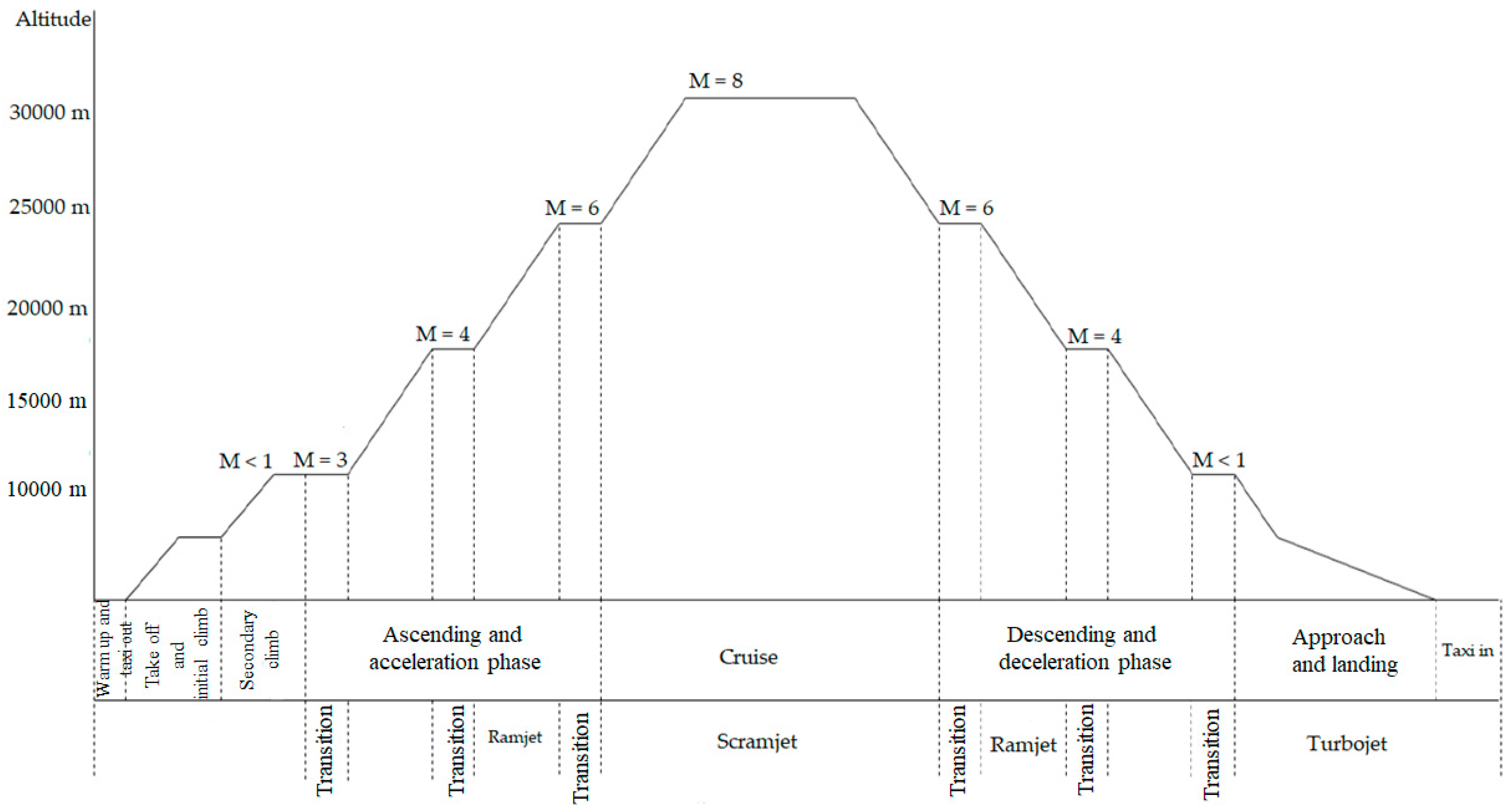
As is true for the body of the aircraft, different engine technologies function best at different altitudes and velocities. None of the current commercial aircraft are fitted with engines capable of propelling them to velocities beyond Mach 0.85. This second challenge will be addressed by using different engine technologies, ramjet and scramjet. However, for the aircraft to be a viable option for airline companies, it must take off like any other aircraft from a conventional runway. This is unfeasible with ramjet and scramjet engines since they cannot produce static thrust. To do so, the aircraft will be equipped with a combination of engines. Turbojet engines deliver thrust by burning jet fuel with compressed air. The air is compressed through an inlet, then typically through a multistage compressor before entering the combustion chamber. Once mixed, the air and fuel are ignited to produce thrust. The hot burnt gases are passed through a turbine and then a nozzle. The mechanical work produced by the turbine drives the compressor. Where turbofans are limited to Mach 0.85, turbojets, like the ones fitted on the Concorde and the SR-71 can operate at higher velocities. Turbojet will be used during taxing and take-off altitude of 0 m up to 10,000 m where it will be propelled to a velocity of Mach 3.0–3.5.
Figure 1 describes the typical flight profile of the plane from take-off through landing (13). It shows which engine will be used for each portion of the journey including the altitude and speed range. The flight profile includes a stepped approach from the take-off phase to cruise and from cruise to landing. This is needed to allow the pilot to switch between the different engines, to go from turbojet to turbo-ramjet, turbo-ramjet to ramjet, ramjet to scramjet and the inverse of this process for the landing phase.
2.1. Dual-Mode Engine Configuration
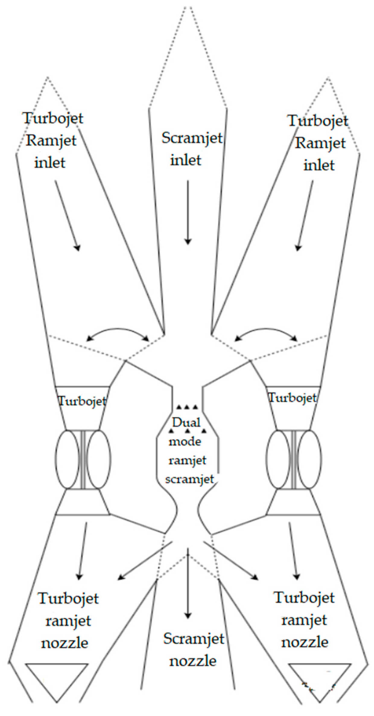
In this design, a dual-mode combustion chamber which can be used as both ramjet and scramjet is employed. The engine configuration includes, two turbojet engines with two ramjet inlets to channel the air into the turbojet engines. When, the aircraft has reached a velocity of Mach 3 and an altitude of 10,000 m, part of the air is channeled into the dual-mode combustion chamber which is configured in ramjet operation. The turbojets and ramjet work hand in hand until Mach 4 is reached at an altitude of 20,000 m. At this stage the turbojet ceases to work. All the air entering the inlets is routed into the ramjet. Finally, once a speed of Mach 6 is reached, the dual-mode combustion chamber is switched from ramjet to scramjet mode. Scramjet mode will remain in operation for the most part for the flight where it will reach its maximum velocity of Mach 8 at altitude 30,000 m.
Another improvement to the body from the previous work [
13] is the use of a series of “flaps” or “doors” used to channel the airflow into the different engines. These are shown as dotted lines in
Figure 2. These devices prevent unnecessary drag formation by letting air enter engines which are not in use. For example, at Mach 8, the ramjet and turbojet inlets are not being used and thus can be “closed off” to make the body of the aircraft more aerodynamically streamlined. The need of two turbojet engines is required for safety reasons. In the situation where one turbojet engine fails at low altitude, i.e., take-off and landing phase, a second engine is required to ensure the safe landing of the aircraft.
2.2. Dual-Mode Combustion Chamber Operating Principles
The design of the combustion chamber allows for the combustion chamber to be used at either subsonic or supersonic combustion. This characteristic makes it suitable for a wide range of operating velocities. The dual-mode supersonic combustion engine design is patented by Currant and Stull [
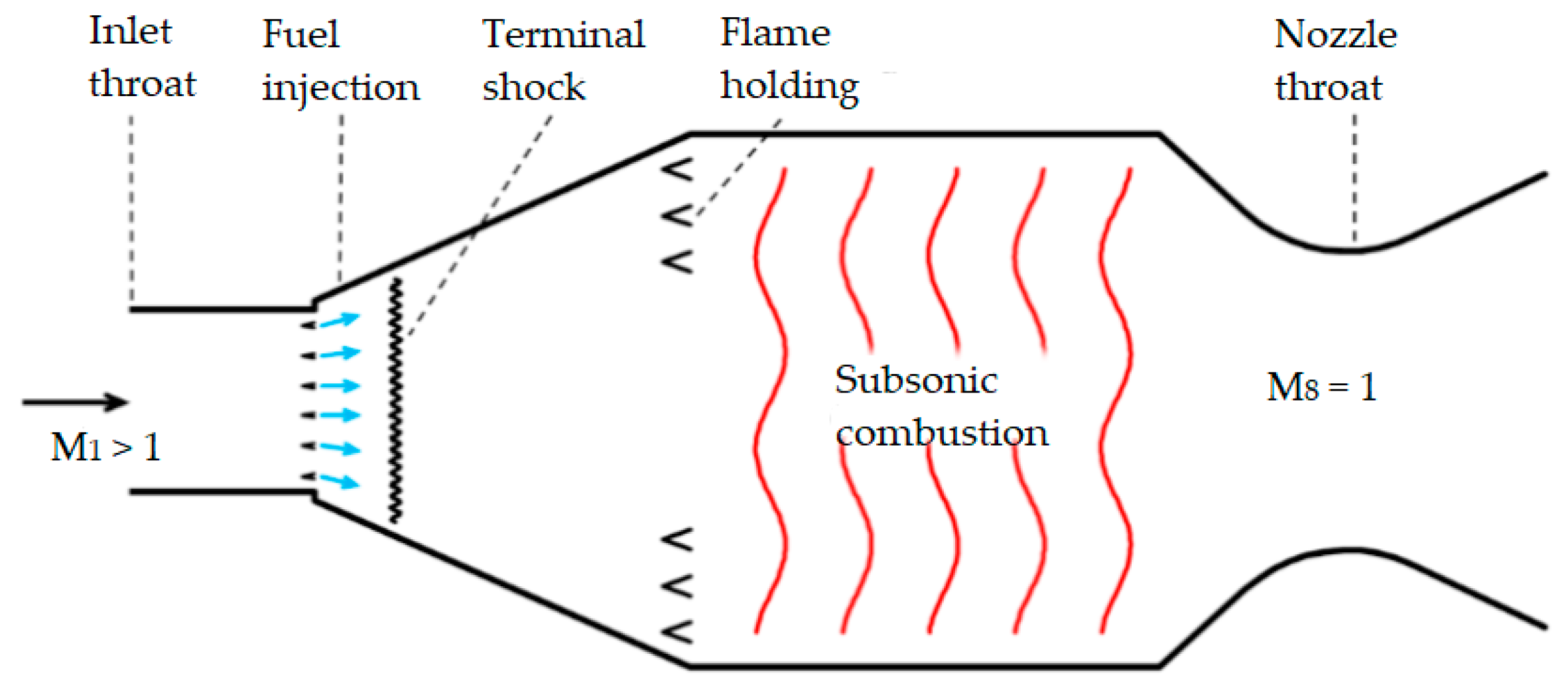
20]. During the use of ramjet, the airflow needs two throats; the first throat is to reduce the flow speed to subsonic level for combustion, and the second one is for supersonic acceleration in the nozzle (
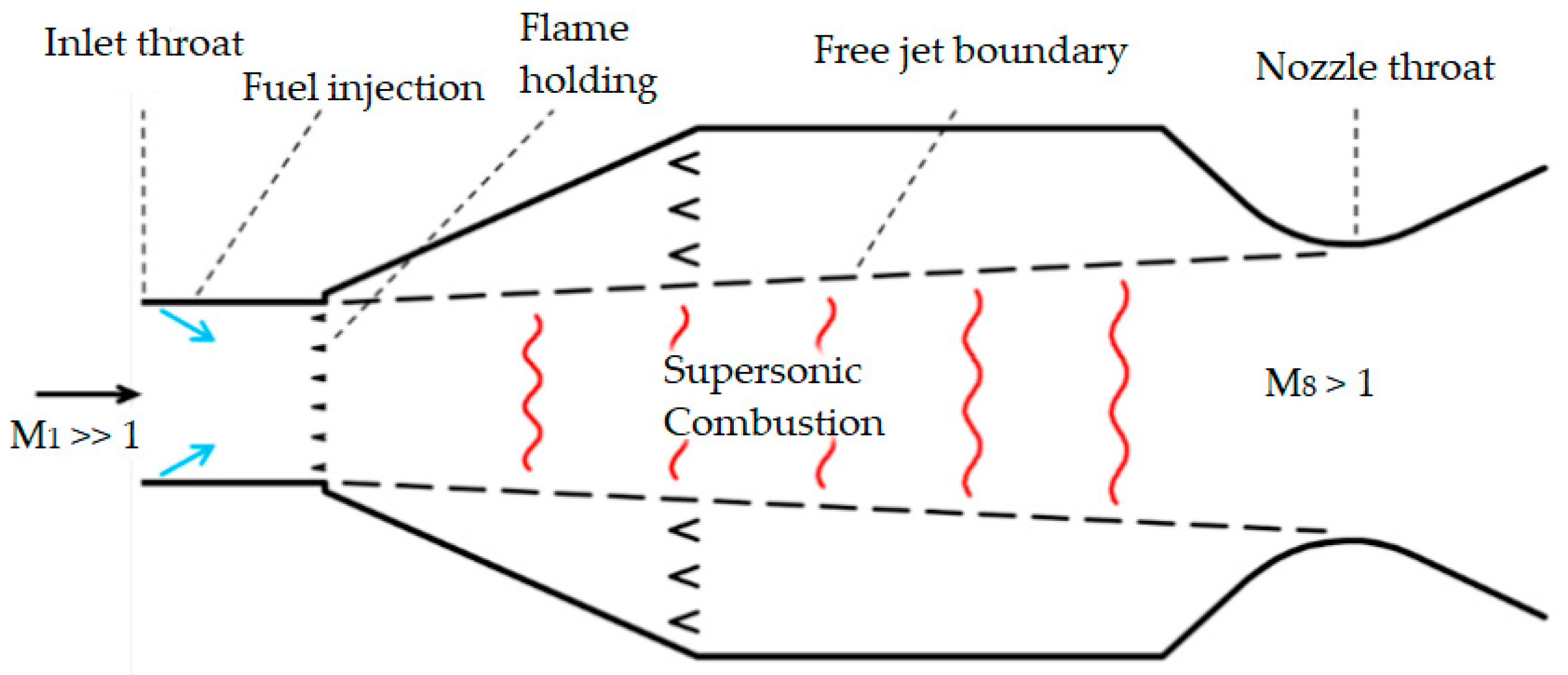
Figure 3). However, for scramjet the throats are not needed as it can be seen in
Figure 4.
The difference between a ramjet and scramjet engine is their operation speed range and their combustion process velocities. The operation speed range of a ramjet lies between Mach 2 and 5 while the combustion process occurs at subsonic velocity. A scramjet can function from Mach 4 upwards while the combustion process occurs at lower supersonic velocity.
There are technical challenges with this type of hybrid engine configuration, due to the modulation of the thermal location, fuel distribution, flame holding and the actual ignition of the fuel in the combustion chamber in such a large cross-section [
13]. When used at high operating velocities, Mach 5 and above, the supersonic combustion occurs in an unconfined supersonic free-jet surrounded by a subsonic combustion. The free-jet is channeled towards a variable throat area nozzle. As see in
Figure 4, the supersonic propulsive stream is not in contact with the wall of the combustion chamber. To adjust the nozzle throat cross section area, a control system is needed to manage the reattachment of the flow when in scramjet operation. Thus, the use of a dual-mode engine could be beneficial as it offers up a way of building up to the required Mach 8 speed value through an integration of two engine systems. This leads to space, weight and maintenance cost savings. Having less combustion chambers increases the space for extra payload or fuel and reduces the need to maintain multiple combustion chambers. The localized heating effects are negated due to the flow not being in contact with the combustion chamber walls. A secondary flow of air can be introduced into the engine to act as a cooling agent whilst increasing the pressure. However, this consideration will not be studied in this paper.
The high-speed air enters the engine through the inlet where it is compressed through a series of shockwaves. As it is compressed, it is slowed down to subsonic speeds in the case of a ramjet engine and remains supersonic in scramjet engine. However, the flow is still slowed down to improve the efficiency of the combustion chamber. Once in the combustion chamber, the fuel is injected and mixed with the air. In the case of ramjet, flame holders (igniters) may be required to maintain a steady combustion of the fuel. In scramjet engine, the fuel automatically ignites due to the extreme temperatures of the flow entering the combustion chamber. Finally, for both engines, the flow is expanded and ejected though the nozzle. The nozzle’s role is to convert the pressure and thermal energy of the air and fuel into kinetic energy which in turn generates thrust.
Both the ramjet and the scramjet use the forward motion of the engine to compress the incoming air. This means no moving parts are required to compress the air to the required pressures and temperatures for the combustion process. The Dual-Mode Free-Jet combustor has only been tested in a simulated computational environment thus far. This paper will validate the result using CFD analysis.
2.3. Fuel
The Dual-Mode Free-Jet combustor by Triffny and Dupold [
13] was modelled using ethylene fuel. This paper will be carrying out simulations using hydrogen as a fuel; hence, this section will compare the characteristics of ethylene and hydrogen fuel. Fuel properties are provided in
Table 1, below.
A study from the University of Queensland [
21] investigates the suitability of hydrogen, methane and ethylene fuels at Mach 8. From this analysis, it can be clearly seen that despite hydrogen having the higher energy content per mass, it is also the least dense of the three fuels. Therefore, consideration for the need of large storage tanks will have to be made. This is one of the driving factors for using a dual-mode combustor, the space gained by combining two separated combustion chambers into one, can be allocated to increase fuel storage.
Another influencing factor for choosing pure hydrogen fuel as opposed to hydrocarbon-based fuels, is the sustainability it offers. Its only by-product is water vapor (H
2O). The high energy content of hydrogen provides a significant advantage as highlighted by El-Sayed [
17]. The specific impulse potential of hydrogen is significantly higher allowing for better performing accelerations. More so, it can be used to fuel turbojets, ramjets and scramjet engines; hence, it could be used from take-off to cruise velocity, therefore relieving the need for alternative fuel for the other engines. The water vapour produced by the combustion of hydrogen does have a polluting effect at very high altitude [
22]. The presence of water vapor in the stratosphere, has a warming effect of the troposphere, hence being a contributor in global warming [
23].
2.4. Injection and Combustion
The challenge with supersonic combustion is achieving sufficient mixing of the fuel and air within the combustor [
24]. Due to the high flow velocities, the fuel has only a short amount of time to mix [
25]. The extreme conditions must allow the fuel to atomize, mix, ignite and produce a steady and reliable combustion. This is especially challenging for hydrocarbon fuels, due to the slow reaction rates and the short residence time involved that limits fuel-air mixing [
26]. Taking into consideration the Rayleigh flow effect, heat addition from adding fuel into the supersonic flow may result in a decrease of the stagnation pressure. An excessive decrease in pressure will impact the efficiency of the engine negatively and may result in the supersonic flow slowing down to subsonic speeds. Hence, for the fuel to add energy to the flow, the air must not enter the combustion chamber at too high a temperature. The injection system used by Trefny and Dippold III [
13] consists of 3 annular ring injectors.
For any given amount of fuel, there is a finite amount of oxygen required to burn it. Excess in oxygen does not hinder the combustion, and when complete combustion is preferred, oxygen is typically supplied in excess. The chemical interaction between the fuel and the oxidizers such as ethylene-air and nitrogen, and hydrogen-air and nitrogen, creates complex reactions species. The combustion simulation must model these sequences of molecular reactions, which release energy while being converted into products.
3. Computational Methodology
The computational simulations have the goal to simulate and quantify the performances of the adapted Dual-Mode Free-Jet design to fit the propulsion requirements at cruise velocity Mach 8 while using hydrogen instead of hydrocarbon-based fuels. Commercial software Ansys Fluent was used to perform the simulations. Investigation on the effect adjusting the fuel to air ratio, from equivalence ratio 0.4 to 1.0, has on the temperatures within the combustion chamber will also be studied.
3.1. Geometry
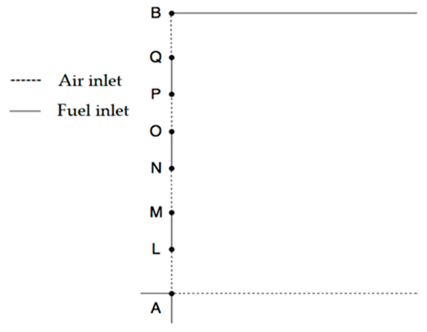
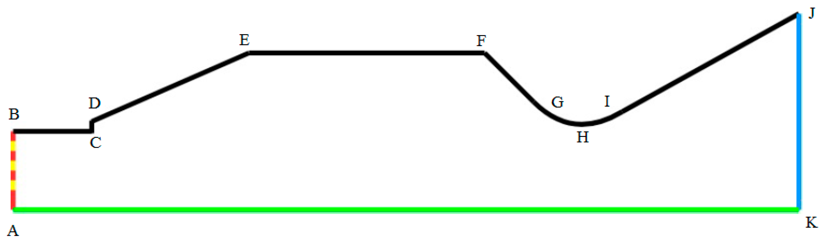
The geometry of the combustor, used for all cases, was identical to the one used in the 2010 study by Trefny and Dippold III [
13] (
Figure 5 and
Table 2). The dimensions were kept identical for the validation case and were modified to suit the FAME objectives. The dotted line between A and K is the symmetry line. The step at D and C is to induce flow separation from the wall. The curve through point G–H–I is defined with two tangent constraints to the neighboring line F–G and I–J and fixed height for the throat, point H. The nozzle section is not part of the combustor final design, but its only purpose is to demonstrate expansion of the flow after passing the throat (H) during simulation. The ramjet and scramjet nozzles designed are dimensioned to be fitted at point H. The injection system is positioned between points A and B, as shown in
Figure 6.
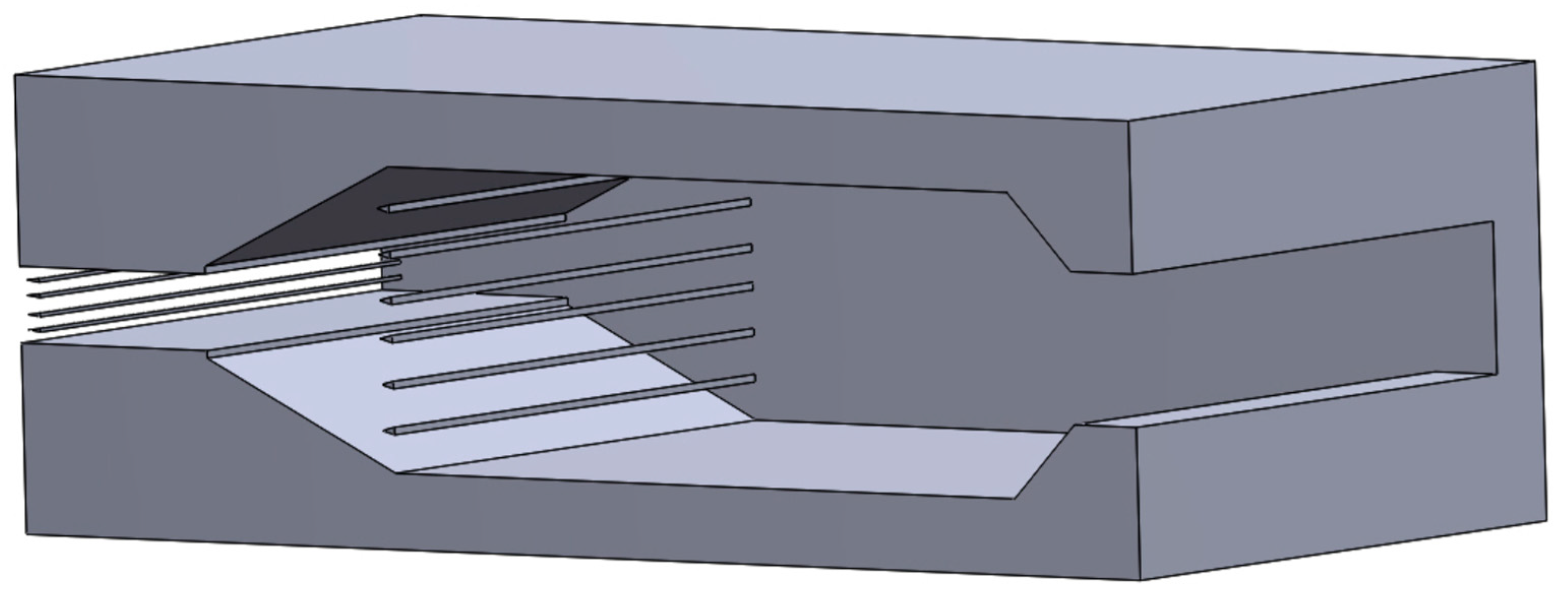
The dimension of the injectors had to be drastically reduced in size to accommodate the replacement fuel, from ethylene to hydrogen due to the higher calorific content. In a ramjet-scramjet engine, the combustion chamber can be asymmetrically shaped, meaning it does not need to be cylindrical or axially symmetrical [
22].
Figure 7 shows the asymmetrical design of the Dual-Mode Free-Jet combustion chamber.
3.2. Boundary Types
The inlet (fuel and air) and outlet boundaries were specified using pressure. The computational domain was halved employing symmetry conditions so as to reduce the computational effort. The boundary conditions are described in
Table 3.
3.3. Numerical Model
There is no single turbulence model able to universally predict every turbulent flow. Choosing the correct model can have significant impact on the accuracy of the flow modelling. The calculation carried out by NASA used a time-accurate, fully implicit code developed in-house [
13]. In this study the k-ε model was employed. RANS models are applicable to a wide range of applications while proving appropriately accurate for this study. Density based models are recommended for supersonic simulation since they provide good convergence properties as opposed to pressure-based models. For the solution of the governing equations, an implicit approach with the Roe-flux difference splitting for calculating the convective flux was used. The flow, turbulent kinetic energy, and turbulent dissipation were set as second order upwind to obtain more accurate solutions. Single step, volumetric reactions and finite rate reaction for the turbulence-chemistry interaction were enabled with the hydrogen–air mixture (H
2 + O
2), to model the scramjet combustion. The Y+ value was maintained less than 1. A Species Transport Laminar Finite Rate model will be employed to model the volumetric reaction combustion process where the turbulent fluctuations are ignored. It uses the Arrhenius Rate of Reaction Law. The chemical mechanisms are integrated into Fluent ANSYS using the CHEMKIN tool. This software is used for solving complex chemical kinetics problems.
3.4. Mesh
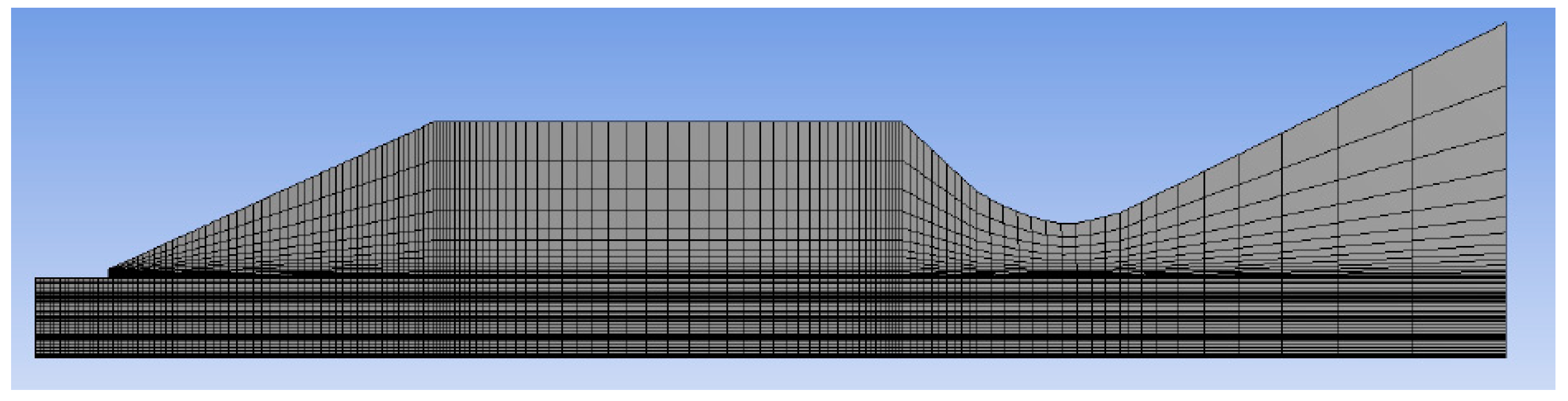
The computational domain was meshed using a quadrilateral mesh and using edge sizing wherever possible.
Figure 8 shows the grid pattern generated to the NASA specifications. The grid shown in the figure is with reduced mesh density for better clarity. The node number used for validation was in accordance with number used by NASA, approximately 392,000.
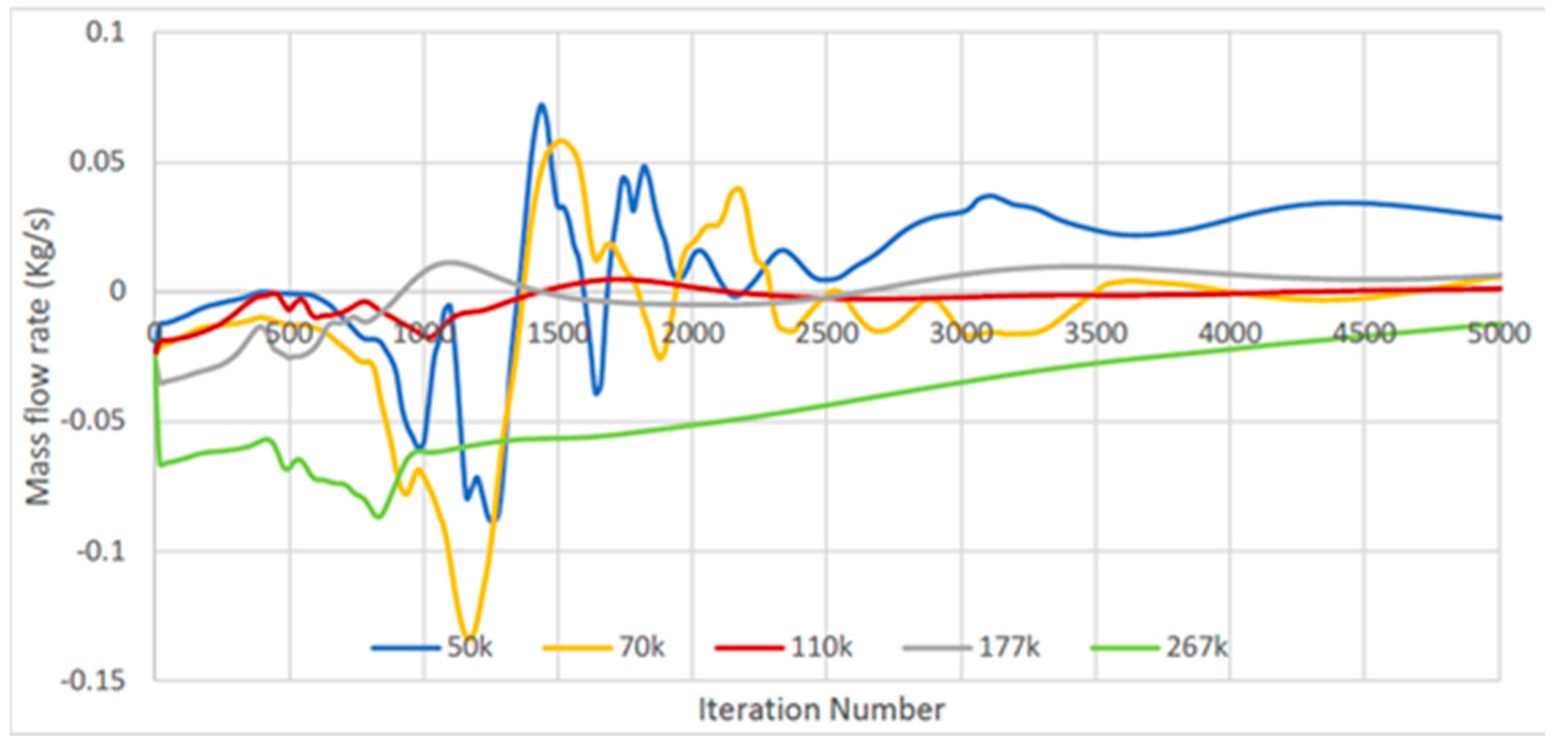
The grid independence study was carried out using ANSYS Workbench, where 5 different mesh densities were created, a 50,000, 70,000, 110,000, 177,000 and 267,000. The 110-k cell mesh showed the fastest convergence to steady mass flow rate of 0 kg/s (
Figure 9). Coarser meshes provided a very unstable value at the beginning of the simulation and would end up taking a greater amount of time to converge. Denser meshes provided more stable results; however, the convergence would require a greater amount of time to converge, particularly for 267,000 cells and above. It was decided upon the results of the mesh refinement study to carry all simulations with a mesh count of 110,000 cells.
3.5. Species Model
The three-step reaction with 7 species for ethylene–air is described in
Table 4 [
23] and the one step reaction for hydrogen–oxygen is described in
Table 5.
4. Results and Discussion
4.1. Validation
In this section the numerical methodology adopted in this study is validated by comparing the simulation results with experimental results provided by NASA [
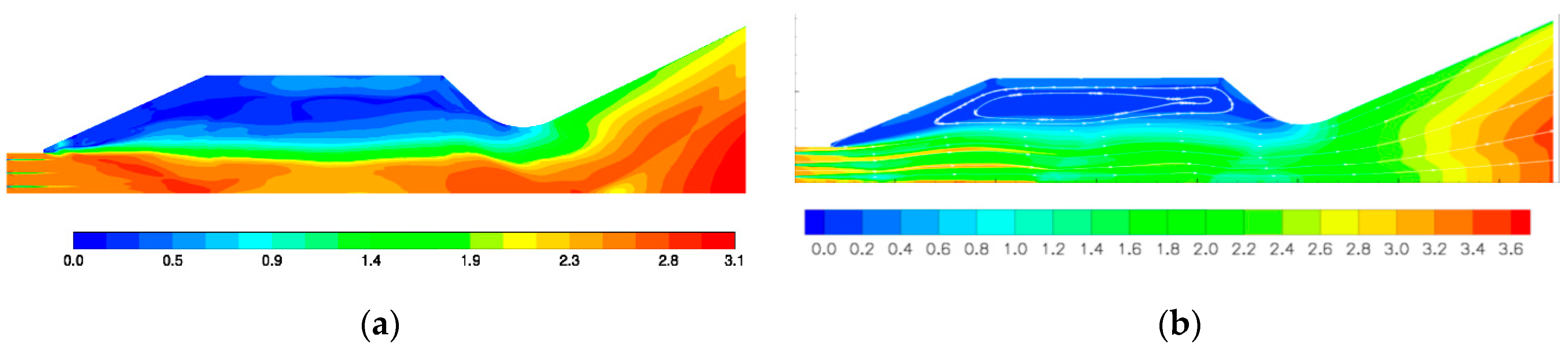
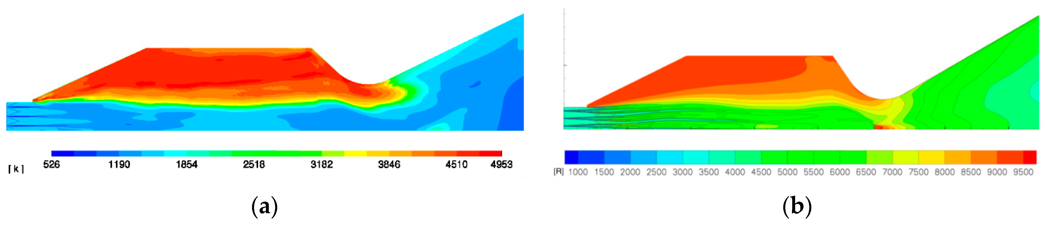
19]. The results in this section will be limited to flow property comparison at Mach 8. The NASA numerical experiment shown on the right in
Figure 10 shows fast incoming air entering the combustion chamber whilst the fuel is traveling at a lower speed than Mach 1. The flow continues to slow down until reaches past the throat at about Mach 2.0 where it proceeds to speed up to Mach 3.6 in the nozzle. In the validation case shown on the left, the fuel injection is seen to be similarly slower than the incoming air; however, the flow does not slow down as dramatically as in the NASA study. This may be because the fuel is acting as a speed reducing agent as it mixes with the air. The fuel does not seem to penetrate as far into the combustion chamber. Another difference can be noticed that the stagnating recirculation zone is separated by an intermediate zone of flow before the free-jet stream of air at Mach 2.4 in the computational analysis. Nonetheless, the flow reattaches in both cases at the throat at a speed above Mach 1 and accelerates downstream.
The extreme temperatures in the recirculation region of 5000 kelvin (9500 Rankin) were observed in the NASA numerical experiment,
Figure 11b. This was successfully replicated in the validation study. The subsonic recirculating flow can be seen to be in the region of 5000 kelvin degrees. These high temperature causes ionizing of atoms, which is undesirable for combustion. This can be addressed by adjusting the amount of fuel being introduced into the combustion chamber. Although differences exist in the Mach and temperature plots, the setup provides results, which provide sufficient validations for further analysis.
4.2. Effect of Equivalence Ratio on the Flow Characteristics
Following the validation run of the NASA design, the model was modified to meet the specifications for the present study. The numerical methodology parameters used are identical to the validation case, except that the species and materials parameters have been changed to reflect the use of hydrogen fuel. The effect of equivalence ratio (EQ) on the flow characteristics has been studied in detail.
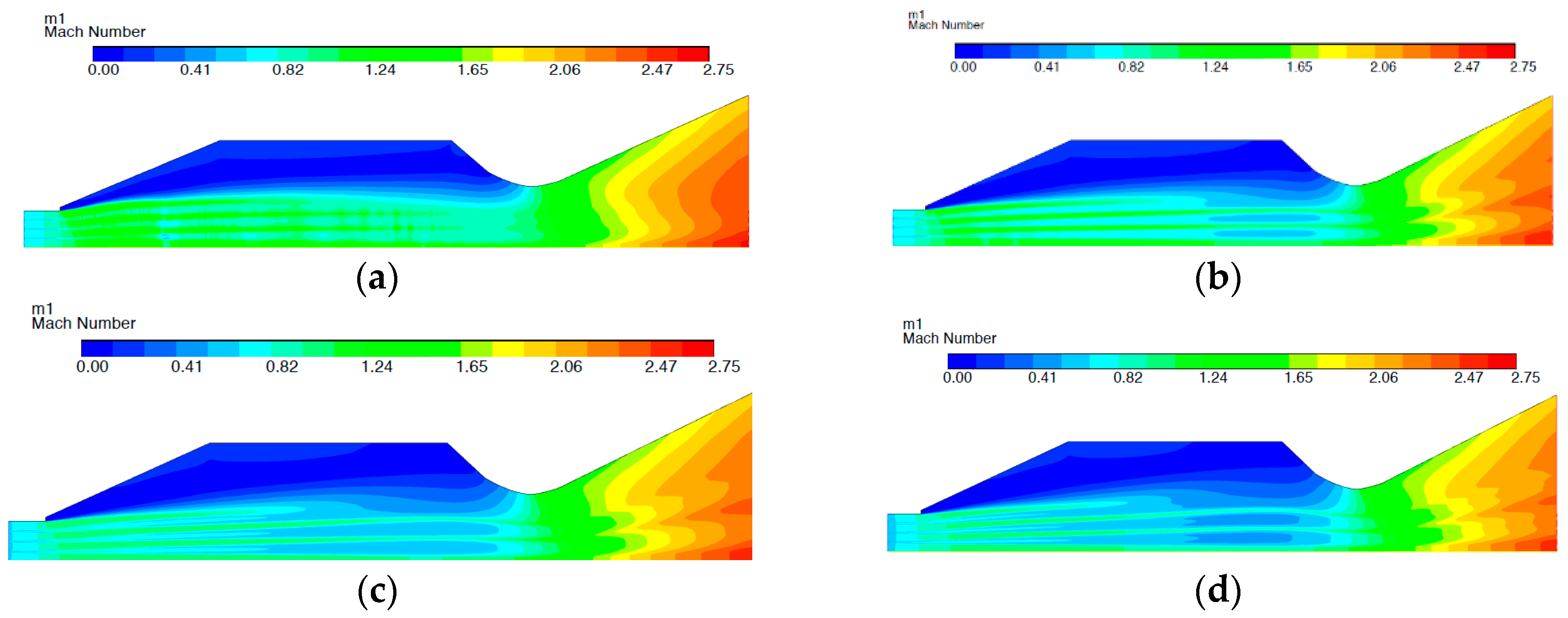
4.2.1. Mach Number
As seen in
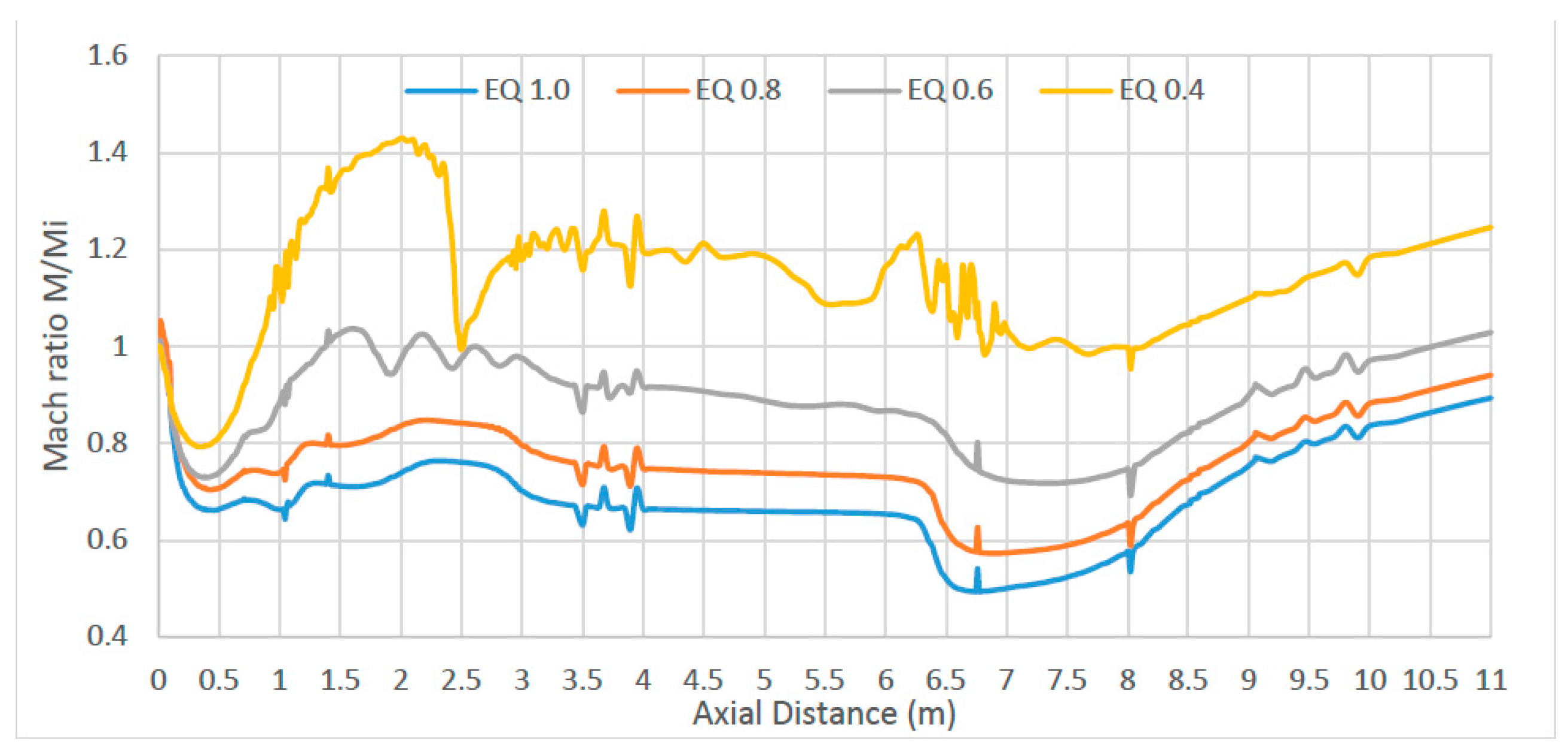
Figure 12a–d, the Mach velocity at the inlet is below Mach 1.0. This suggests that a normal shock perpendicular to the flow has formed at the very entrance of the inlet, which causes the flow to slow down as explained above. This shock formation causes the flow to go into subsonic velocities in the combustion chamber. In essence, the scramjet engine is behaving as a ramjet where combustion occurs at subsonic flows. The free-jet is at subsonic velocity instead of supersonic. The free-jet is surrounded by a lower speed static region of flow. The fuel can be seen to be traveling through the free-jet at a lower speed and the surrounding air from the inlet. Looking at the Mach ratio along the axial centerline distance of the combustor (
Figure 13), significant fluctuations occur at Equivalence ratio 0.4 where little fuel is injected. The peak velocity occurs in the divergent part of the combustor, between 0.5 m and 2.2 m in all cases. However, only for equivalence ratio 0.4 does the Mach reaches 1.4 times the inlet speed.
The equivalence ratio mixture 0.6 peeks at a ratio 1, meaning its maximum speed is equal to its inlet speed (Mi). EQ 0.8 and 1.0 show poor Mach ratios below 1 throughout the combustion chamber. The Mach plots in
Figure 12a–d shows the flow velocities to be above Mach 1 prior to reaching the throat, hence allowing the flow to accelerate in the nozzle. However, the expected Mach velocity between Mach 2.5 to 3.0 required for the scramjet nozzle to produce enough thrust was not achieved. As the amount of fuel is increased, from equivalence ratio 0.4 to 1.0, the Mach value remains unchanged. This suggests that a lean fuel-air mixture would have an as good effect of thrust as a stoichiometric mixture.
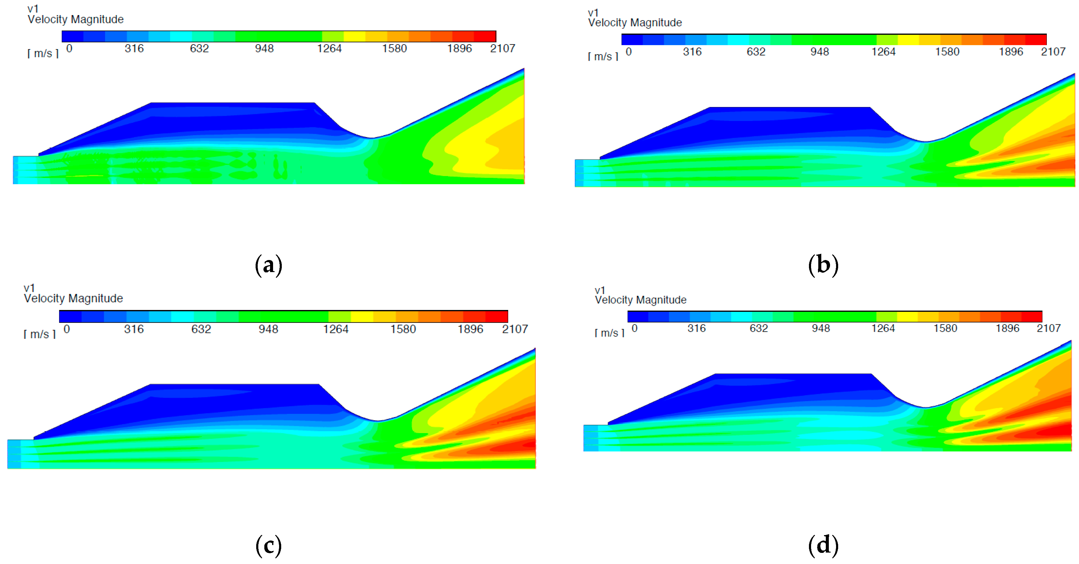
4.2.2. Velocity
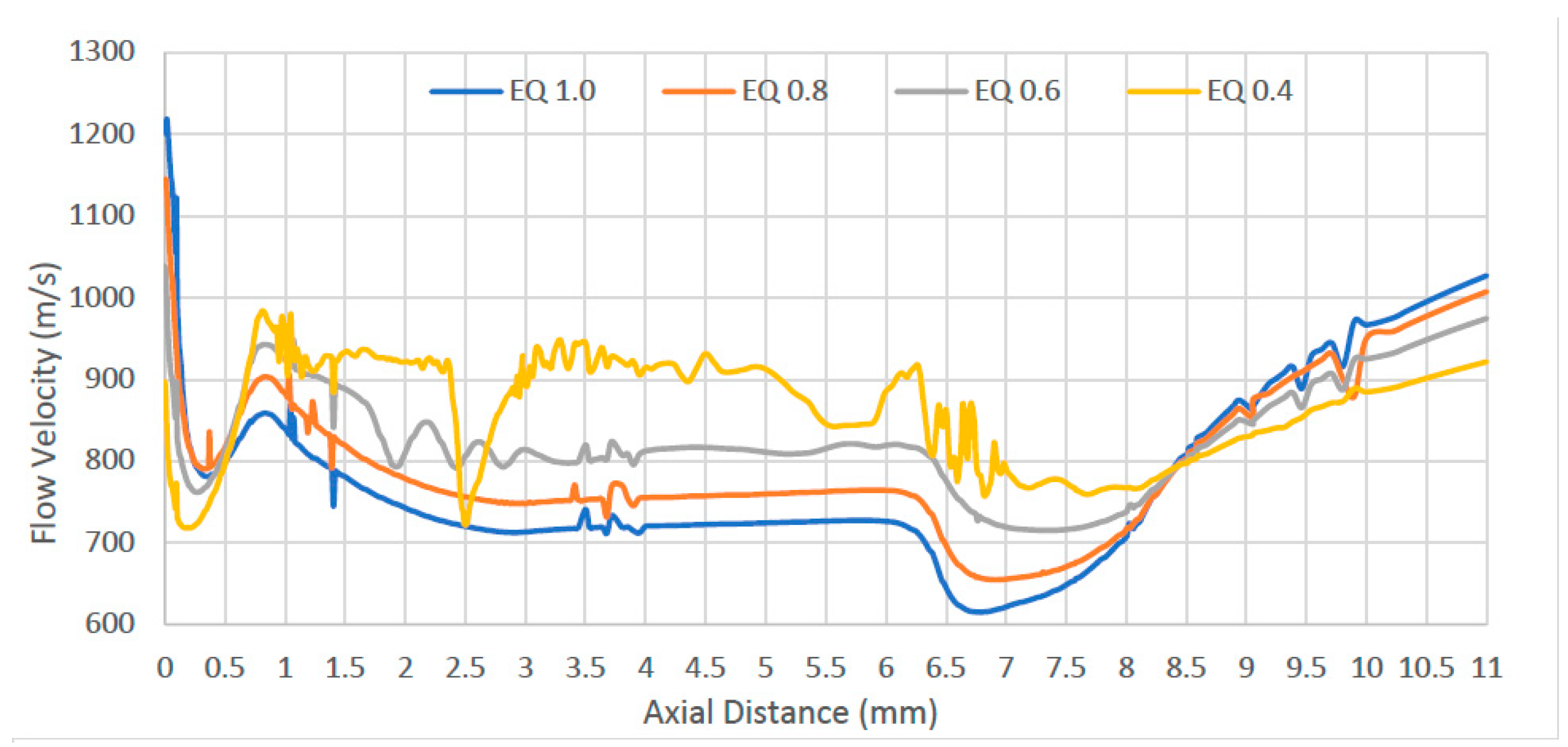
Similar to the Mach plots, the velocity plots in
Figure 14a–d show a relatively fast subsonic, free-jet flow surrounded by a slower, recirculating zone of air above it. The freestream jet reattaches at the throat where in reaches a velocity of about 650 to 850 m/s depending on the fuel content of the mixture. The relationship between fuel-to-air ratio and flow acceleration becomes clear in the nozzle as shown by
Figure 15. With an EQ of 0.4 and 0.6, the lean mix of fuel does not allow the air to accelerate above 960 m/s in the nozzle. However, with higher fuel mixtures, EQ 1.0 and EQ 0.8, the flow accelerates beyond 1000 m/s.
Figure 14b,c shows two dark red streaks of fast moving flow in the nozzle at EQ 0.8 and EQ 1.0, which are not present at EQ 0.4 and are only faintly visible at EQ 0.6. This, contrary to the Mach flow plots, would suggest that a stoichiometric mixture would be preferable to a lean fuel-air mixture. The disparity between the Mach and Velocity plots are due to the local speed of sound changing throughout the combustion chamber caused by the temperature increase, as seen in the next section.
4.2.3. Temperature
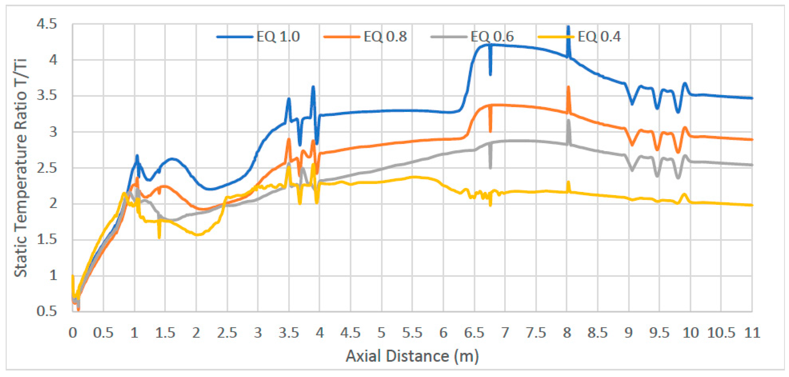
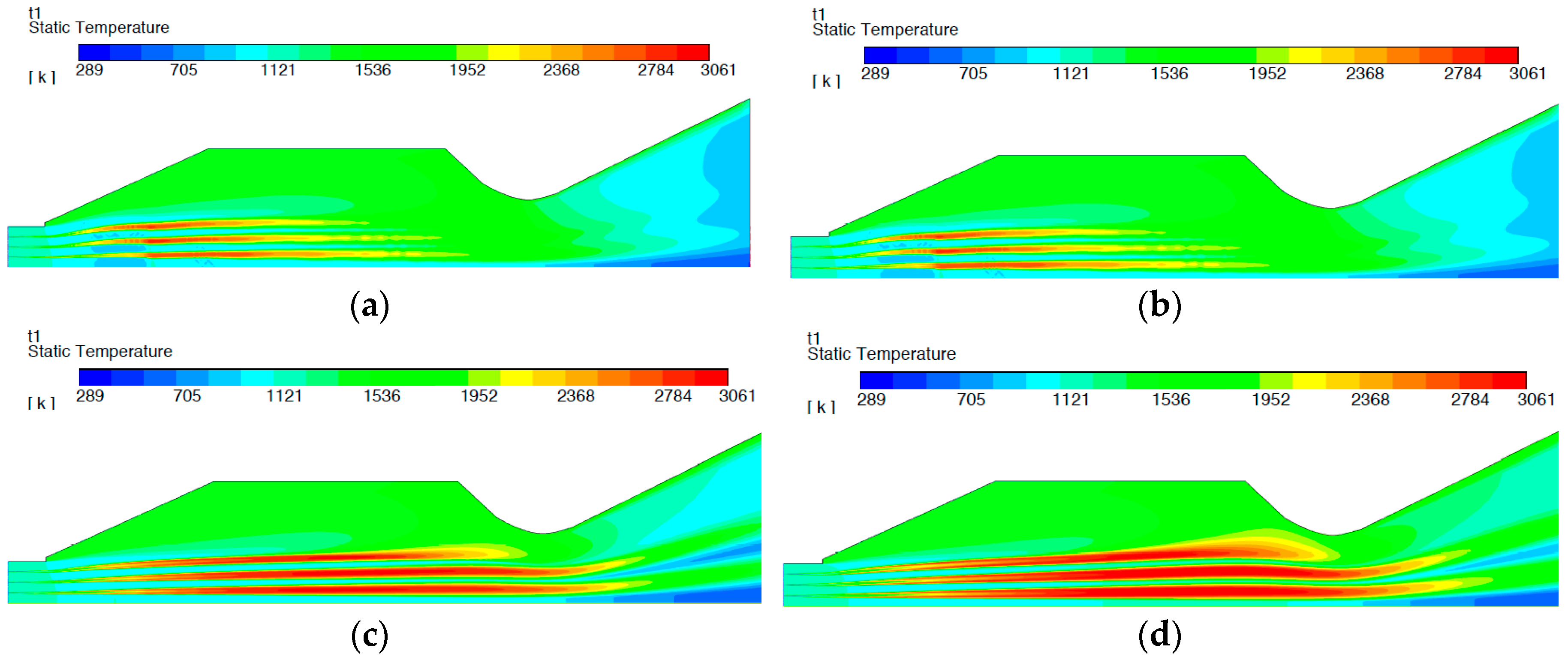
As expected, the combustion process releases energy in the form of heat proportionally to the amount of fuel introduced into the combustion.
Figure 16 shows the static temperature of the fuel throughout the domain. The mixture with EQ of 0.4 only reaches about twice the temperature within the combustor. The temperature for the stoichiometric mixture, EQ 1.0, increases to approximately 3.3 times within the constant diameter section where it peaks at a ratio of 4.3 in the throat. Comparing the four-different fuel-air mixtures (
Figure 17a–d), there is only temperature increase within the free-jet. The recirculation zone remains at a relatively low temperature of 1500 K compared to the 5000 K observed by the NASA study. The low temperatures at the nozzle part may be attributed to the presence of reverse flow at the pressure outlet at the lower equivalence ratios of 0.4 and 0.6 at least, but further work is clearly required in this area.
With EQ 0.4, most of the thermal energy release occurs in the divergent part of the combustion chamber. The energy release ends approximately halfway down the combustion chamber, meaning that all the fuel is consumed prior to reaching the throat. With the high fuel-to-air mixtures, the thermal energy release occurs from injection until the throat of the combustion chamber. The temperature in the inlet can be observed to be relatively low in all four cases.
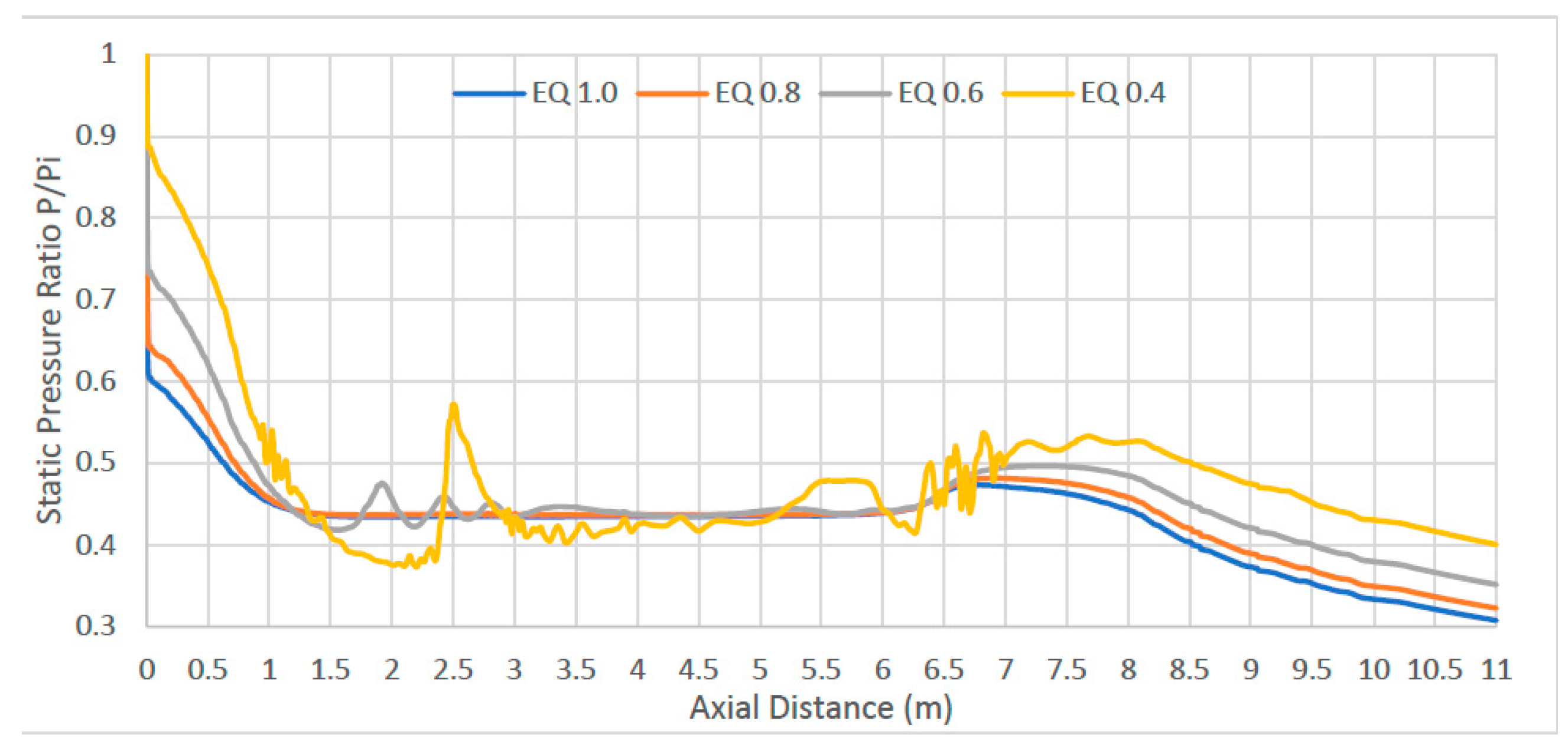
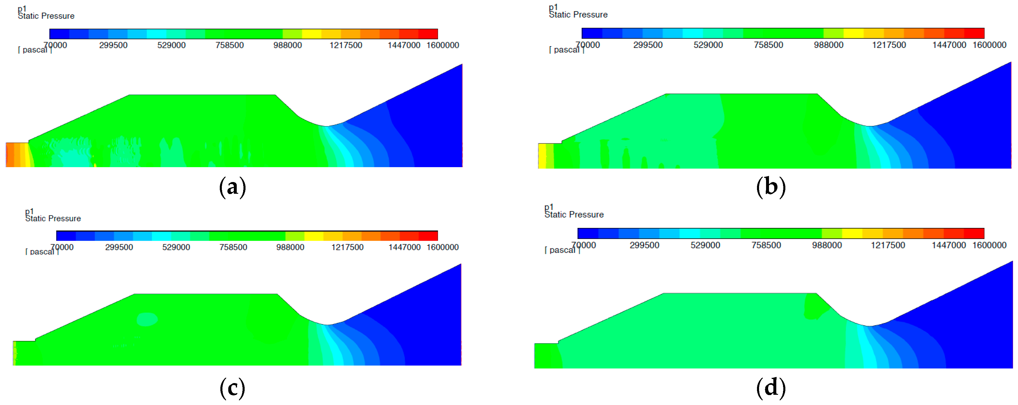
4.2.4. Pressure
Figure 18a–d and
Figure 19 plot the pressure drops throughout the combustion chamber. These results display the loss in performance of the engine. The pressure does show some fluctuation near the throat. The slight pressure increase in the throat followed by a pressure drop in the nozzle is expected as the flow is slowed down before re-accelerating in the nozzle. It is expected to have a pressure drop across the combustion chamber due to the formation of shock trains within it. The presence of shock formation can even promote mixing; however, the trade-off of efficient mixing comes with the decrease of total pressure recovery.
5. Conclusions
The aim of this report was to adapt the Dual-Mode Free-Jet design, first tested by Trefny and Dippold III, and fit the FAME18 project propulsion requirements at cruise velocity Mach 8. The goal of the FAME project was to design an advanced engine configuration for sustained commercial hypersonic flight. The study was based on the prior work of the FAME team to provide improved designs of the inlet and nozzle for both the ramjet and scramjet, whilst also investigating the feasibility of the use of a Dual-Mode Free-Jet combustion chamber design proposed by Trefny and Dippold. The dual-mode combustion engine or dual ramjet-scramjet is a system that operates as a ramjet at low supersonic speeds and then transforms to a scramjet at higher Mach numbers between 6 to 8. This design also benefits from being useable over a wide range of velocities while keeping reasonable performances.
The 2010 numerical investigation by Trefny and Dippold III, was limited to hydrocarbon fuel operation and challenges were encountered with extreme static temperatures within the combustion chambers. This report adapted the Dual-Mode Free-Jet design to fit the FAME propulsion requirements at cruise velocity Mach 8 while using hydrogen instead of hydrocarbon-based fuels.
In this Computational Fluid Dynamics (CFD) investigation the k-ε model was employed. The Y+ value was maintained at less than 1. A Species Transport Laminar Finite Rate model was employed to model the volumetric reaction combustion process. The chemical mechanisms were integrated into the Fluent ANSYS software package using the CHEMKIN tool (used for solving complex chemical kinetics problems).
The Dual-Mode Free-Jet design was validated against numerical results provided by NASA at Mach 8. The model captured well all of the salient flow features such as flow deceleration (although not quite as dramatically as in the NASA model) and the stagnating recirculation zone separated by an intermediate zone of flow in the model, with the flow in both cases reattaching at the throat at a speed above Mach 1. In addition, the extreme temperatures in the recirculation region observed in the NASA numerical experiment were also successfully replicated in the validation study. The normal shock wave formation at the entrance of the inlet could not be prevented in this study. A way of preventing it would be implementing a variable inlet and nozzle height. Although, differences exist in the Mach and temperature plots, these are relatively minor, resulting in sufficient validations for further analysis.
This new design allows the ramjet and scramjet engines to be combined into a single unit allowing for a volume reduction of 53% compared to prior work by the same group in the field (17). The aircraft is then capable to be run over a large range of Mach speeds using a single combustion chamber whilst allowing for significant space saving and reduced maintenance cost. As this study was the first to peer review the design, a series of challenges were faced when modelling the combustion chamber.
Being the first study to study the unique combustion chamber design, this study provides useful and time saving insights for subsequent studies to develop upon the results. The size reduction of the combustion system for this aircraft as well as the sustainability improvement by switching from ethylene to hydrogen fuel are significant progress which encourages future advancement in research regarding this design.


