Morphing Wing Droop Nose with Large Deformation: Ground Tests and Lessons Learned

 , , , ,
Abstract
1. Introduction
2. Methods
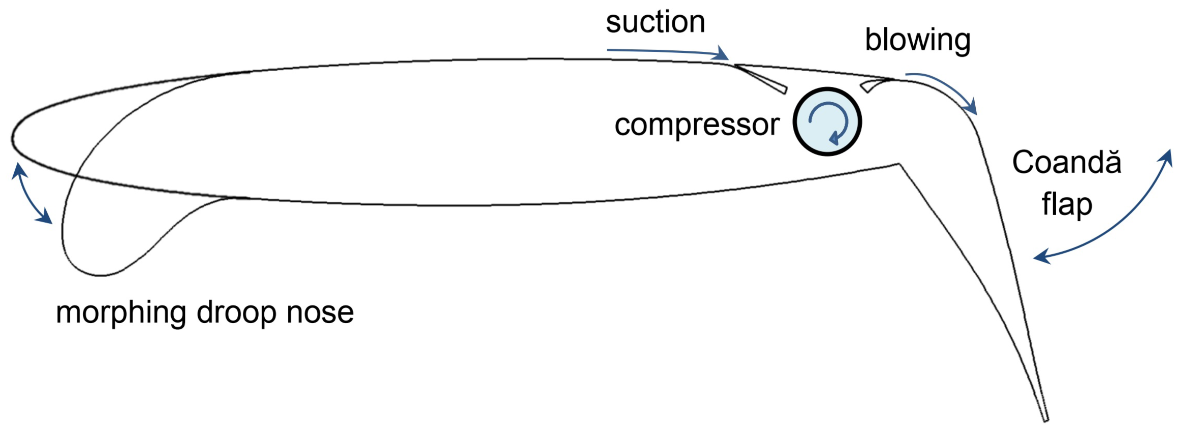
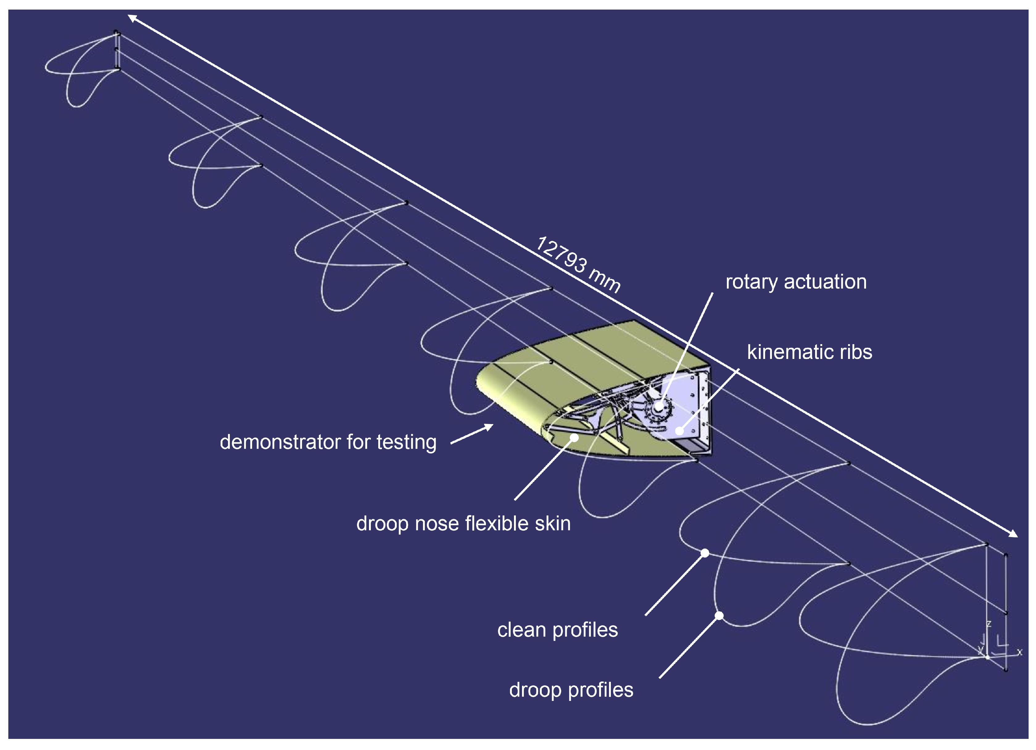
2.1. Aerodynamic Design
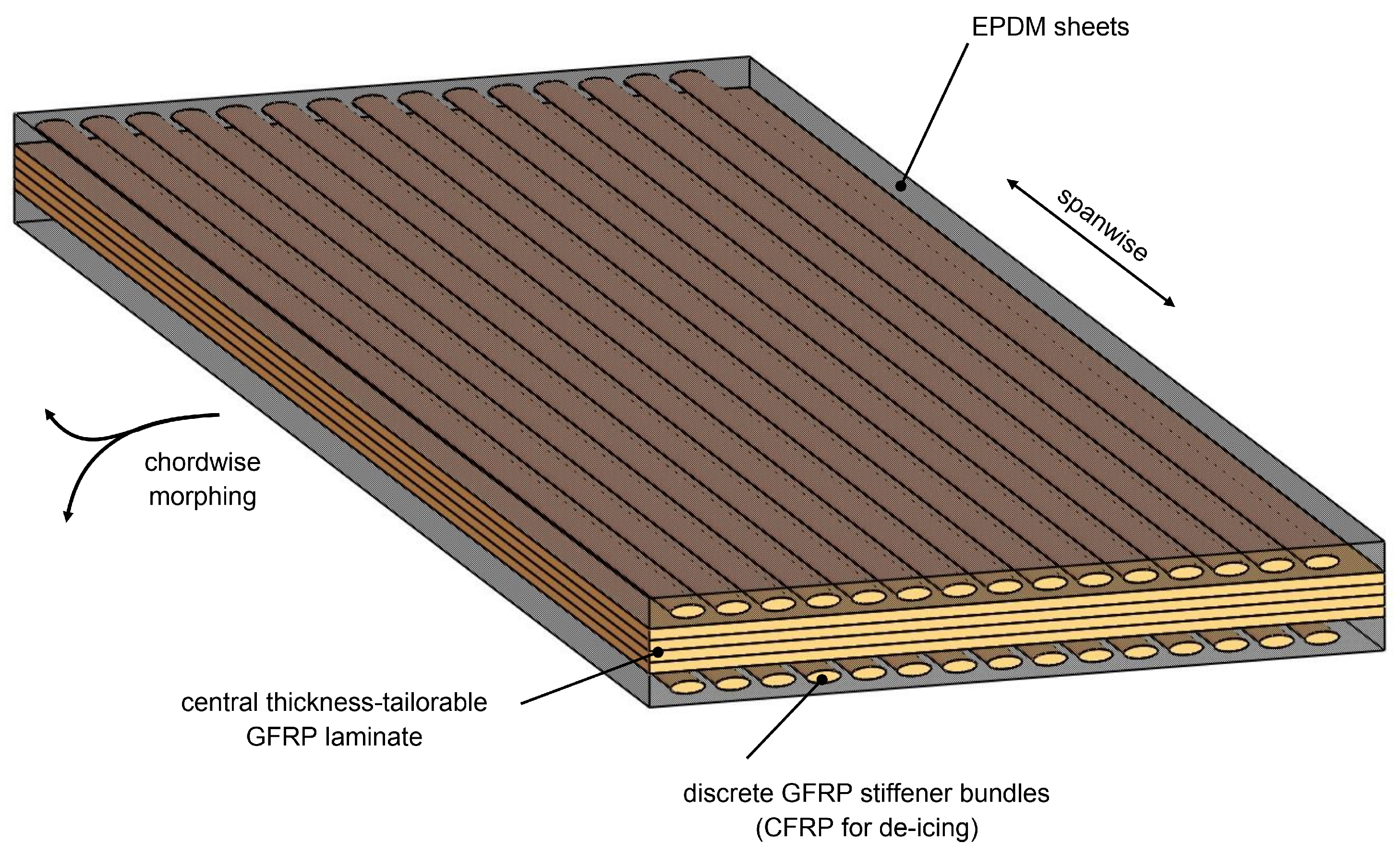
2.2. Structural Design
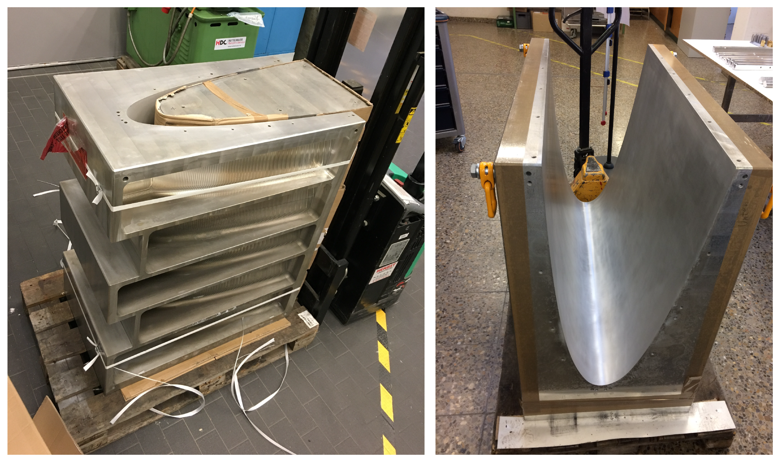
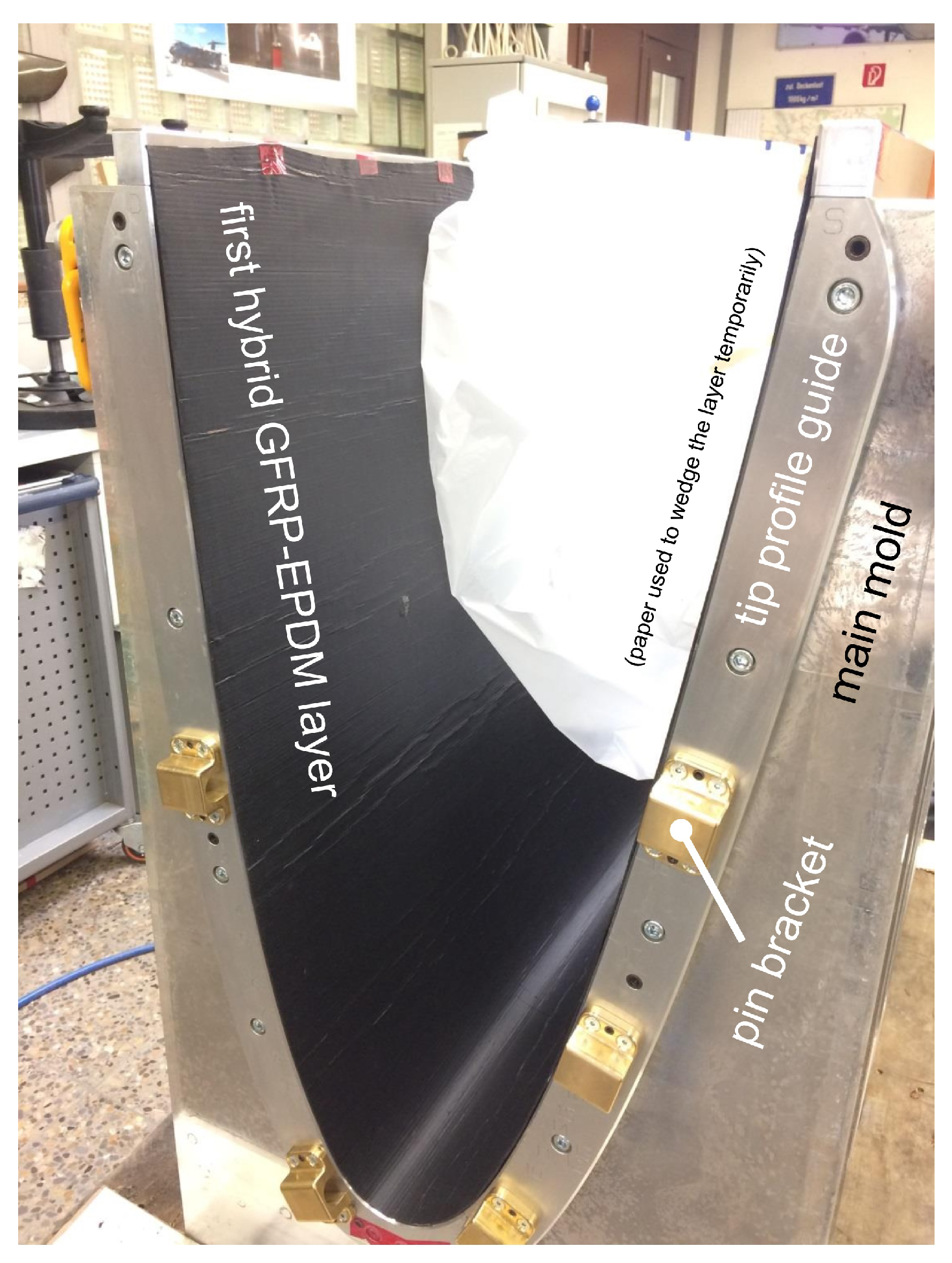
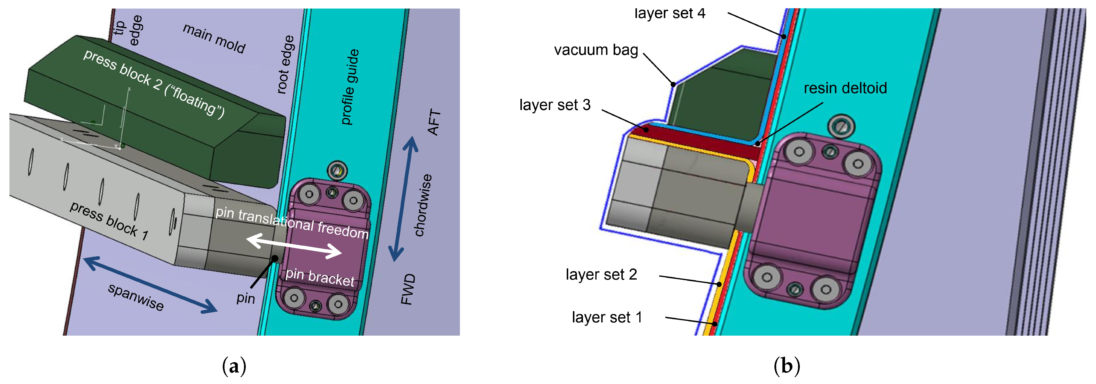
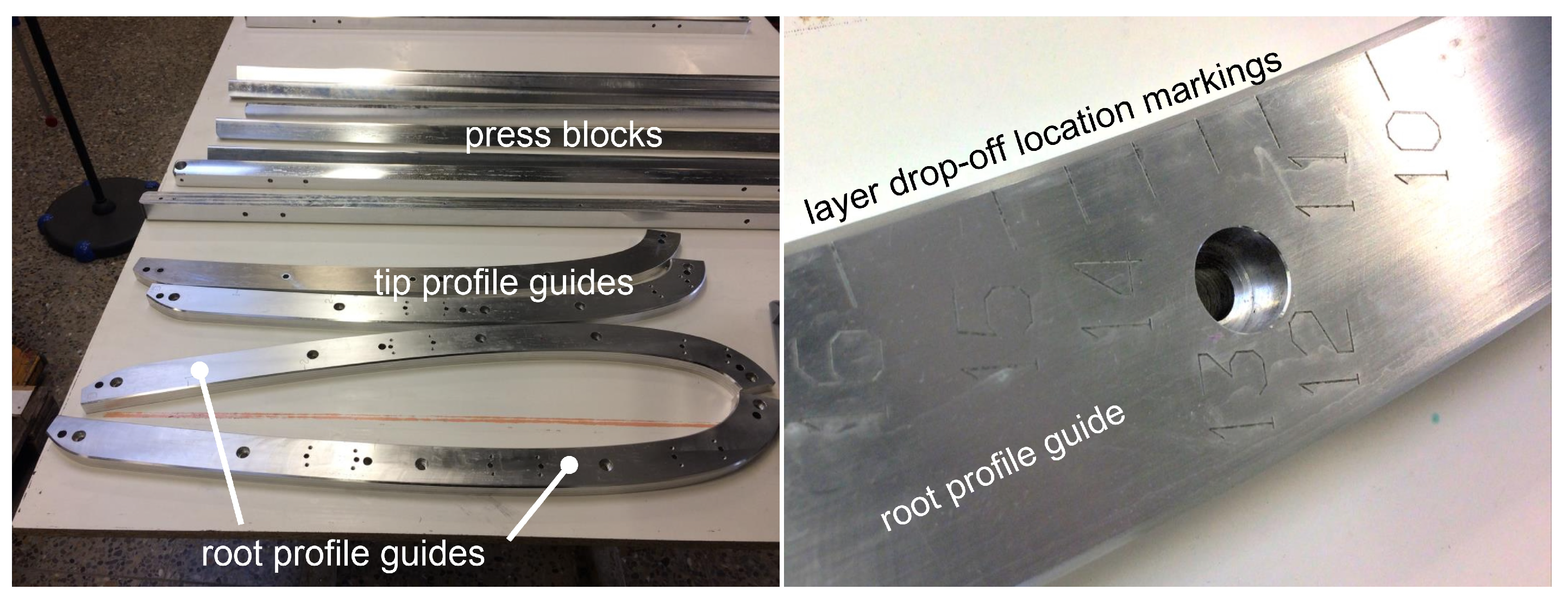
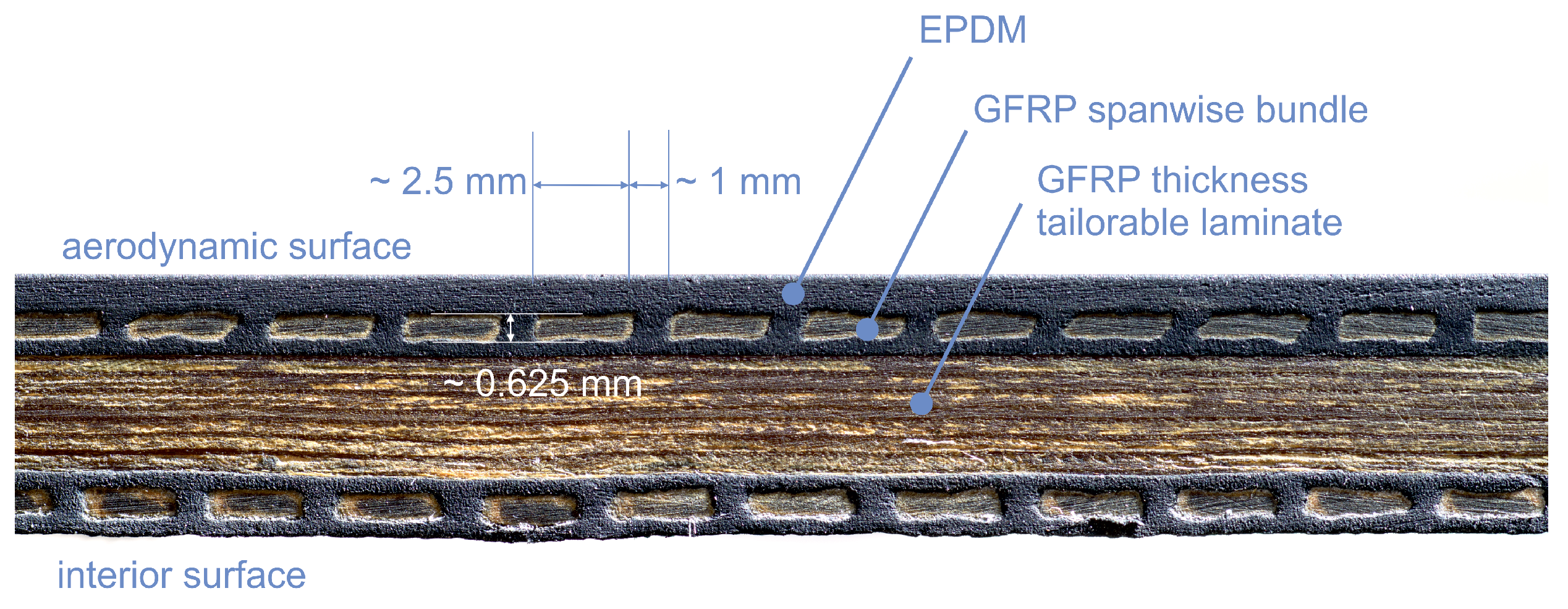
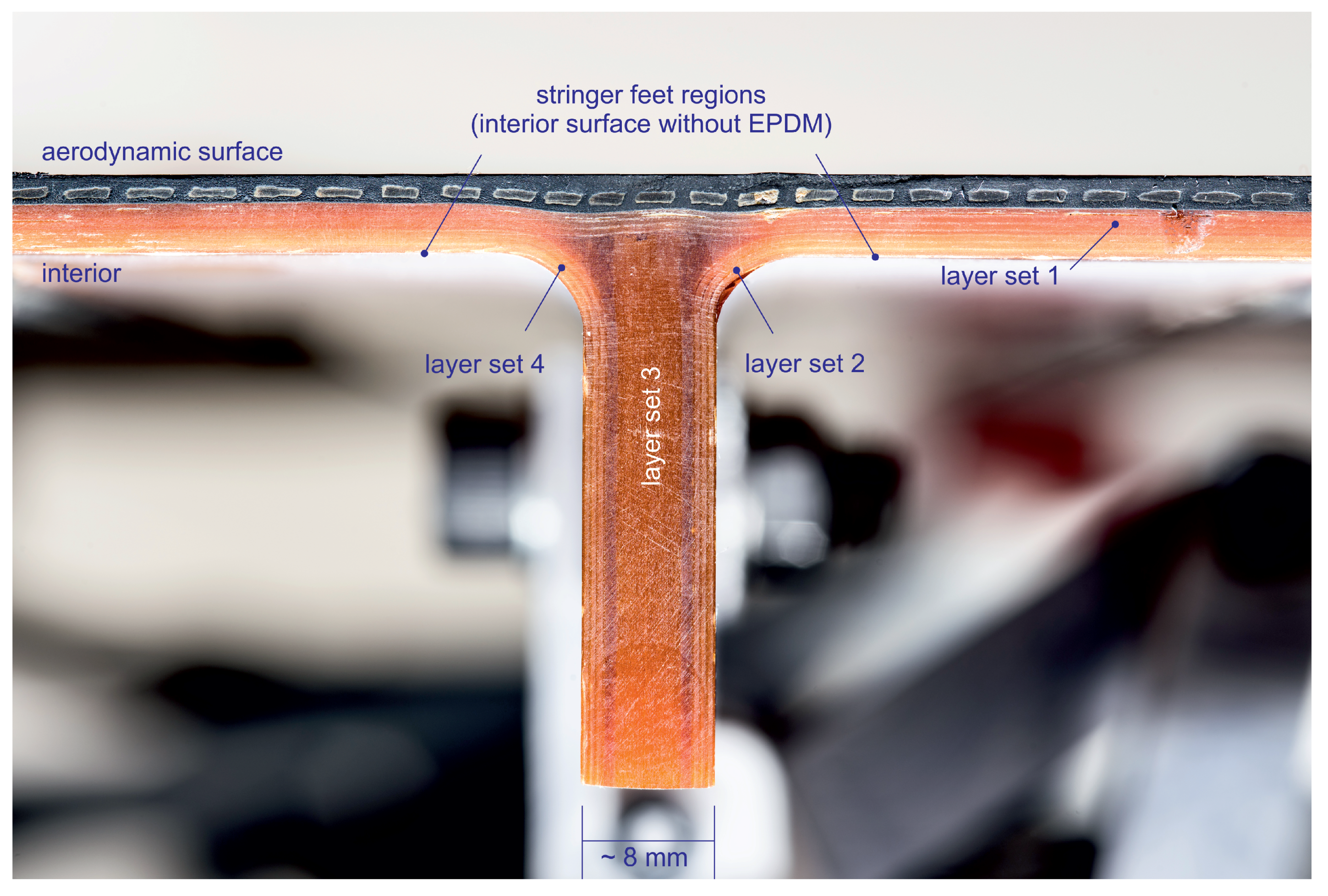
2.3. Skin Manufacturing
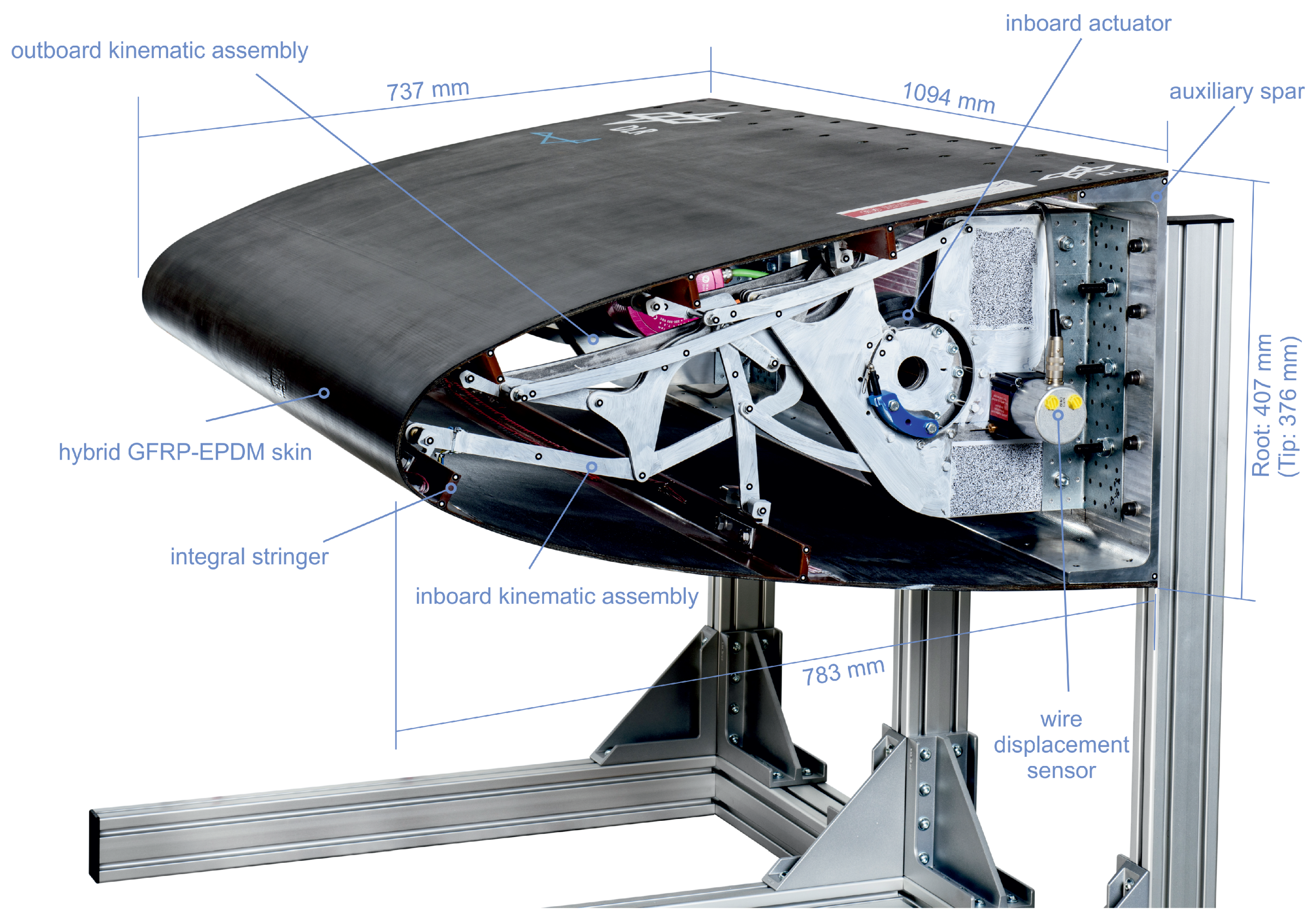
2.4. Kinematic Ribs and Actuators
2.5. Sensing and Measurement
3. Results
3.1. Manufacturing and Functionality Tests
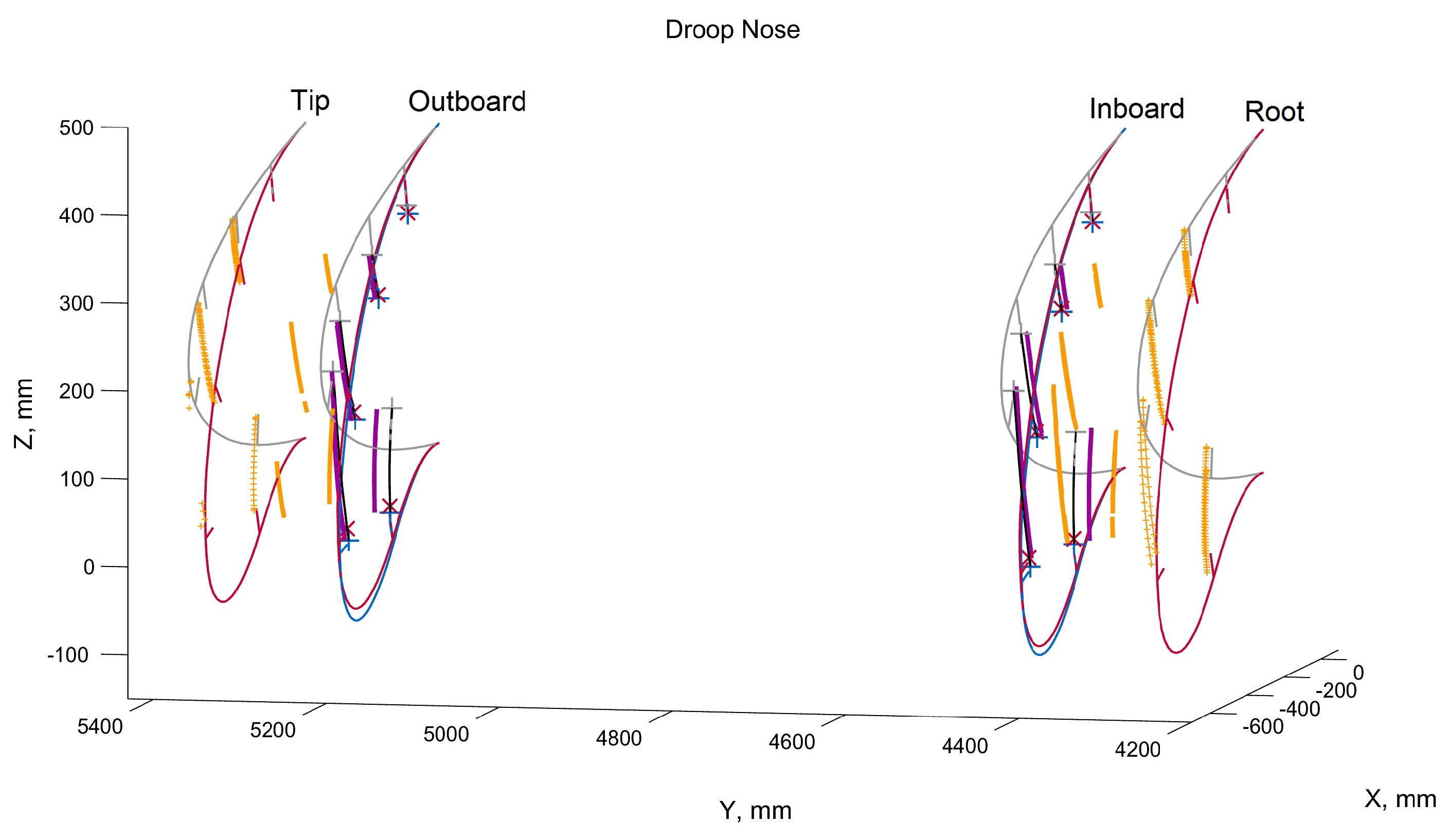
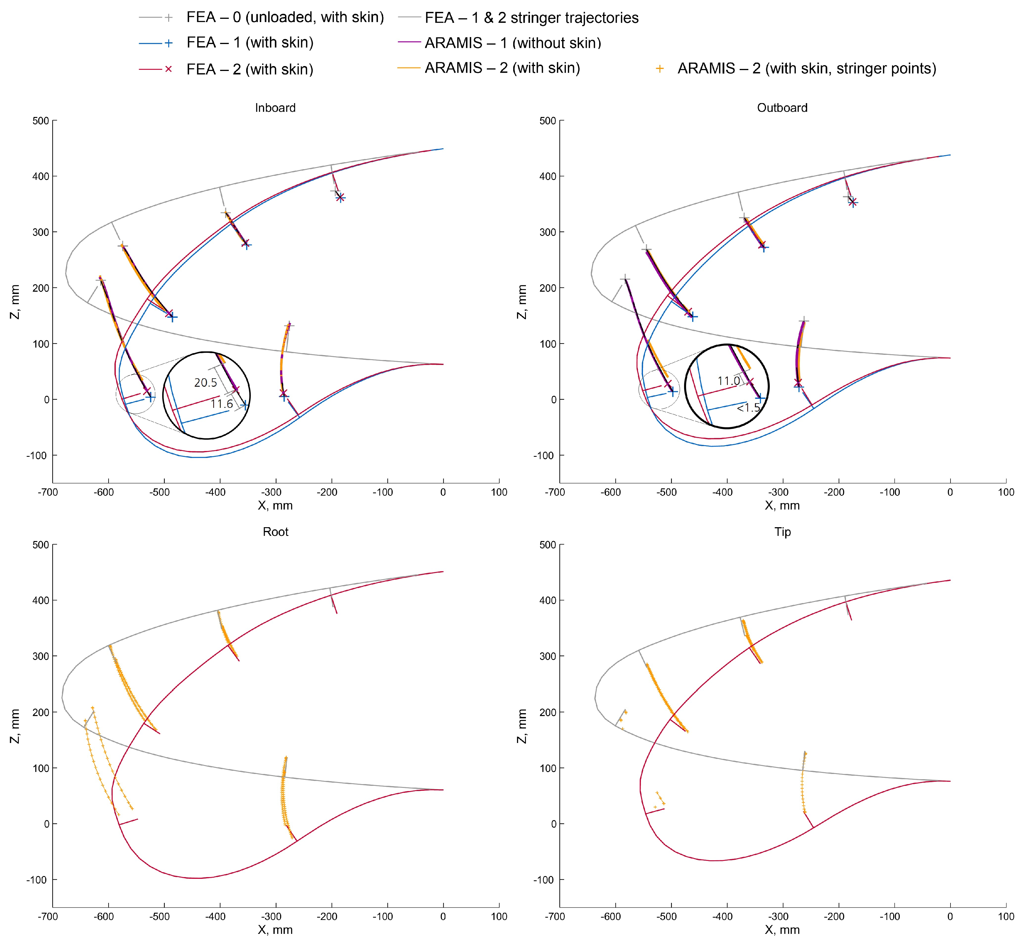
3.2. Shapes
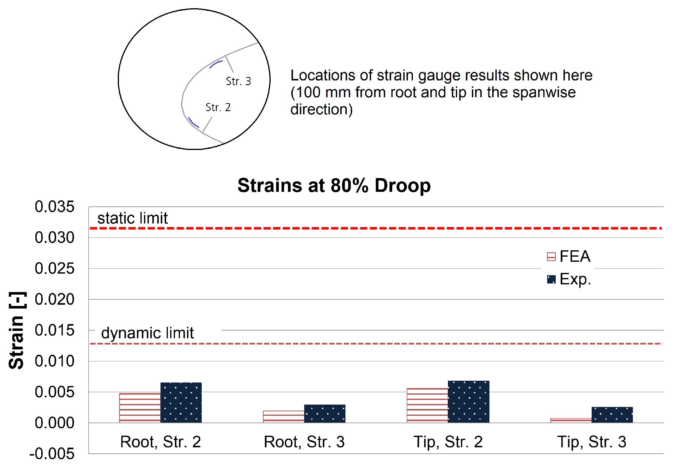
3.3. Strains
3.4. Masses
4. Discussion
5. Conclusions
Author Contributions
Funding
Acknowledgments
Conflicts of Interest
Abbreviations
| CAD | Computer-aided design |
| CFD | Computational fluid dynamics |
| CFRP | Carbon-fiber reinforced plastic |
| DIC | Digital image correlationc |
| EDM | Electrical discharge machining |
| EPDM | Ethylene propylene diene monomer |
| FEA | Finite element analysis |
| GFRP | Glass-fiber reinforced plastic |
| SFB880 | Sonderforschungsbereich 880 (Collaborative Research Center 880) |
| STOL | Short take-off and landing |
| UHMW-PE | Ultra high molecular weight polyethylene |
| VC | Variable camber |
References
- Radespiel, R.; Heinze, W. SFB 880: Fundamentals of High Lift for Future Commercial Aircraft. CEAS Aeronaut. J. 2014, 5, 239–251. [Google Scholar] [CrossRef]
- Seume, J.; Teichel, S.; Burnazzi, M.; Schwerter, M.; Behr, C.; Rudenko, A.; Schmitz, A.; Dörbaum, M.; Atalayer, C. SFB 880—Efficient High Lift. In Proceedings of the Deutscher Luft- und Ramfahrtkongress, Stuttgart, Germany, 10–12 September 2013. [Google Scholar]
- Burnazzi, M.; Radespiel, R. Synergies Between Suction and Blowing for Active High-Lift Flaps. CEAS Aeronaut. J. 2015, 6, 305–318. [Google Scholar] [CrossRef]
- Burnazzi, M.; Radespiel, R. Design and Analysis of a Droop Nose for Coanda Flap Applications. J. Aircr. 2014, 51, 1567–1579. [Google Scholar] [CrossRef]
- El Sayed, M.Y.; Oswald, P.; Sattler, S.; Kumar, P.; Radespiel, R.; Behr, C.; Sinapius, M.; Petersen, J.; Wierach, P.; Quade, M.; et al. Open- and Closed-loop Control Investigations of Unsteady Coanda Actuation on a High-lift Configuration. In Proceedings of the 2018 Flow Control Conference, Atlanta, GE, USA, 25–29 June 2018. [Google Scholar] [CrossRef]
- El Sayed, M.Y.; Beck, N.; Kumar, P.; Semaan, R.; Radespiel, R. Challenges in the Experimental Quantification of the Momentum Coefficient of Circulation Controlled Wings. In New Results in Numerical and Experimental Fluid Mechanics XI; Dillmann, A., Heller, G., Krämer, E., Wagner, C., Bansmer, S., Radespiel, R., Semaan, R., Eds.; Springer International Publishing: Cham, Switzerland, 2018; pp. 533–543. [Google Scholar]
- François, D.G.; Radespiel, R.; Semaan, R. Numerical Investigations of Spanwise-Varied Unsteady Coanda Actuation on High-Lift Configuration. J. Aircr. 2018, 55, 1720–1730. [Google Scholar] [CrossRef]
- Diekmann, J.H. Flight Mechanical Challenges of STOL Aircraft Using Active High Lift. J. Aircr. 2019, 56, 1753–1764. [Google Scholar] [CrossRef]
- Zimmer, H. Transverse Force-Connected Body With Variable Profiling, Particularly an Airplane Wing. U.S. Patent 4,252,287, 24 February 1981. [Google Scholar]
- Pierce, D. Fluid Dynamic Lift Generating or Control Force Generating Structures. U.S. Patent 3,716,209 A, 13 February 1973. [Google Scholar]
- Zapel, E.J. Variable Camber Leading Edge for Airfoil. U.S. Patent 4,171,787, 23 October 1979. [Google Scholar]
- Cole, J.B. Variable Camber Airfoil. U.S. Patent 4,553,722 A, 19 November 1985. [Google Scholar]
- Gilbert, W.W. Mission Adaptive Wing System for Tactical Aircraft. J. Aircr. 1981, 18, 597–602. [Google Scholar] [CrossRef]
- Rudolph, P.K.C. High-Lift Systems on Commercial Subsonic Airliners; NASA Contractor Report 4746; National Aeronautics and Space Administration: Moffett Field, CA, USA, 1996.
- Kintscher, M.; Monner, H.P.; Heintze, O. Experimental Testing of a Smart Leading Edge High Lift Device for Commercial Transportation Aircrafts. In Proceedings of the 27th International Congress of the Aeronautical Sciences, Nice, France, 19–24 September 2010; Optimage Ltd.: Edinburgh, UK, 2010; pp. 1–7. [Google Scholar]
- Kintscher, M.; Wiedemann, M.; Monner, H.P.; Heintze, O.; Kühn, T. Design of a Smart Leading Edge Device for Low Speed Wind Tunnel Tests in the European Project SADE. Int. J. Struct. Integr. 2011, 2, 383–405. [Google Scholar] [CrossRef]
- Monner, H.; Kintscher, M.; Lorkowski, T.; Storm, S. Design of a Smart Droop Nose as Leading Edge High Lift System for Transportation Aircrafts. In Proceedings of the 50th AIAA/ASME/ASCE/AHS/ASC Structures, Structural Dynamics, and Materials Conference, Palm Springs, CA, USA, 4–7 May 2009. [Google Scholar] [CrossRef]
- Kintscher, M.; Geier, S.; Monner, H.P.; Wiedemann, M. Investigation of Multi-material Laminates for Smart Droop Nose Devices. In Proceedings of the 29th Congress of the International Council of the Aeronautical Sciences, ICAS 2014, St. Petersburg, Russia, 7–12 September 2014; pp. 1–11. [Google Scholar]
- Kintscher, M.; Kirn, J.; Storm, S.; Peter, F. Assessment of the SARISTU Enhanced Adaptive Droop Nose. In Smart Intelligent Aircraft Structures (SARISTU), Proceedings of the Final Project Conference; Wölcken, P.C., Papadopoulos, M., Eds.; Springer International Publishing: Cham, Switzerland, 2016; pp. 113–140. [Google Scholar] [CrossRef]
- Sodja, J.; Martinez, M.J.; Simpson, J.C.; Breuker, R.D. Experimental Evaluation of the Morphing Leading Edge Concept. In Proceedings of the 23rd AIAA/AHS Adaptive Structures Conference, Kissimmee, FL, USA, 5–9 January 2015. [Google Scholar] [CrossRef]
- Wang, C.; Haddad Khodaparast, H.; Friswell, M.I.; Magrini, A.; Ponza, R.; Benini, E.; Landersheim, V.; Laveuve, D.; Contell Asins, C. Conceptual-level Evaluation of a Variable Stiffness Skin for a Morphing Wing Leading Edge. Proc. Inst. Mech. Eng. Part G J. Aerosp. Eng. 2019, 233, 5703–5716. [Google Scholar] [CrossRef]
- De Gaspari, A.; Riccobene, L.; Ricci, S. Design, Manufacturing and Wind Tunnel Validation of a Morphing Compliant Wing. J. Aircr. 2018, 55, 2313–2326. [Google Scholar] [CrossRef]
- Vasista, S.; Riemenschneider, J.; van de Kamp, B.; Monner, H.P.; Cheung, R.C.M.; Wales, C.; Cooper, J.E. Evaluation of a Compliant Droop-Nose Morphing Wing Tip via Experimental Tests. J. Aircr. 2017, 54, 519–534. [Google Scholar] [CrossRef]
- Lu, K.J.; Kota, S. An Effective Method of Synthesizing Compliant Adaptive Structures using Load Path Representation. J. Intell. Mater. Syst. Struct. 2005, 16, 307–317. [Google Scholar] [CrossRef]
- Jakubinek, M.; Roy, S.; Palardy-Sim, M.; Ashrafi, B.; Shadmehri, F.; Renaud, G.; Barnes, M.; Martinez-Rubi, Y.; Rahmat, M.; Simard, B.; et al. Stretchable Structure for a Benchtop-Scale Morphed Leading Edge Demonstration. In Proceedings of the AIAA Scitech 2019 Forum, San Diego, CA, USA, 7–11 January 2019. [Google Scholar] [CrossRef]
- Thill, C.; Etches, J.; Bond, I.; Potter, K.; Weaver, P. Morphing skins. Aeronaut. J. 2008, 112, 117–139. [Google Scholar] [CrossRef]
- Vasista, S.; Tong, L.; Wong, K.C. Realization of Morphing Wings: A Multidisciplinary Challenge. J. Aircr. 2012, 49, 11–28. [Google Scholar] [CrossRef]
- Weisshaar, T.A. Morphing Aircraft Systems: Historical Perspectives and Future Challenges. J. Aircr. 2013, 50, 337–353. [Google Scholar] [CrossRef]
- Barbarino, S.; Bilgen, O.; Ajaj, R.M.; Friswell, M.I.; Inman, D.J. A Review of Morphing Aircraft. J. Intell. Mater. Syst. Struct. 2011, 22, 823–877. [Google Scholar] [CrossRef]
- Chillara, V.S.; Dapino, M.J. Review of Morphing Laminated Composites. Appl. Mech. Rev. 2019. [Google Scholar] [CrossRef]
- Concilio, A.; Lecce, L. Chapter 1—Historical Background and Current Scenario. In Morphing Wing Technologies; Concilio, A., Dimino, I., Lecce, L., Pecora, R., Eds.; Butterworth-Heinemann: Oxford, UK, 2018; pp. 3–84. [Google Scholar] [CrossRef]
- Vasista, S.; Nolte, F.; Monner, H.P.; Horst, P.; Burnazzi, M. Three-dimensional Design of a Large-displacement Morphing Wing Droop Nose Device. J. Intell. Mater. Syst. Struct. 2018, 29, 3222–3241. [Google Scholar] [CrossRef]
- Schmitz, A.; Horst, P. Buckling of Multiple Discrete Composite Bundles in the Elastomeric Foundation of a Curvature-morphing Skin. Compos. Struct. 2015, 134, 1014–1023. [Google Scholar] [CrossRef]
- Hannig, A. Static and Fatigue Transverse Crack Initiation in Thin-ply Fibre-reinforced Composites. In Forschungsbericht 2018-02; Niedersächsiches Forschungszentrum für Luftfahrt (NFL): Braunschweig, Germany, 2018. [Google Scholar]
- Nolte, F.; Hannig, A.; Horst, P. Investigation of Integral Composite T-Joints under Mixed Mode Loading. Key Eng. Mater. 2018, 774, 197–202. [Google Scholar] [CrossRef]
- Chary, C. Development and Validation of a Bird Strike Protection System for an Enhanced Adaptive Droop Nose. In Smart Intelligent Aircraft Structures (SARISTU), Proceedings of the Final Project Conference; Wölcken, P.C., Papadopoulos, M., Eds.; Springer International Publishing: Cham, Switzerland, 2016; pp. 71–83. [Google Scholar] [CrossRef]
- Vasista, S.; Riemenschneider, J.; Monner, H.P.; Nolte, F.; Horst, P. Manufacture and Testing of a Large-displacement Droop-Nose Morphing Wing Leading Edge. In Proceedings of the AIAA Scitech 2019 Forum, San Diego, CA, USA, 7–11 January 2019. [Google Scholar] [CrossRef]
- Vasista, S.; Rose, M.; Monner, H.P. Optimization Tool Assessment for a Large-displacement Compliant Morphing Wing Leading Edge. In Proceedings of the 27th International Conference on Adaptive Structures and Technologies ICAST2016, Lake George, NY, USA, 3–5 October 2016. [Google Scholar]
- Pepper, R.; van Dam, C. Design Methodology for Multi-Element High-Lift Systems on Subsonic Civil Transport Aircraft; NASA Contractor Report 202365; National Aeronautics and Space Administration: Moffett Field, CA, USA, 1996.


© 2019 by the authors. Licensee MDPI, Basel, Switzerland. This article is an open access article distributed under the terms and conditions of the Creative Commons Attribution (CC BY) license (http://creativecommons.org/licenses/by/4.0/).
Share and Cite
Vasista, S.; Riemenschneider, J.; Keimer, R.; Monner, H.P.; Nolte, F.; Horst, P. Morphing Wing Droop Nose with Large Deformation: Ground Tests and Lessons Learned. Aerospace 2019, 6, 111. https://doi.org/10.3390/aerospace6100111
Vasista S, Riemenschneider J, Keimer R, Monner HP, Nolte F, Horst P. Morphing Wing Droop Nose with Large Deformation: Ground Tests and Lessons Learned. Aerospace. 2019; 6(10):111. https://doi.org/10.3390/aerospace6100111
Chicago/Turabian StyleVasista, Srinivas, Johannes Riemenschneider, Ralf Keimer, Hans Peter Monner, Felix Nolte, and Peter Horst. 2019. "Morphing Wing Droop Nose with Large Deformation: Ground Tests and Lessons Learned" Aerospace 6, no. 10: 111. https://doi.org/10.3390/aerospace6100111
APA StyleVasista, S., Riemenschneider, J., Keimer, R., Monner, H. P., Nolte, F., & Horst, P. (2019). Morphing Wing Droop Nose with Large Deformation: Ground Tests and Lessons Learned. Aerospace, 6(10), 111. https://doi.org/10.3390/aerospace6100111