Article

Damage Localization in Composite Structures Using a Guided Waves Based Multi-Parameter Approach

Department of Industrial Engineering—Aerospace Division, Università degli Studi di Napoli Federico II, Via Claudio 21, 80125 Napoli, Italy
*
Author to whom correspondence should be addressed.
The author has been awarded the 2017 Aerospace Travel Award for his research on reliable solutions for structural health monitoring of complex composite structures using guided waves.
Aerospace 2018, 5(4), 111; https://doi.org/10.3390/aerospace5040111
Submission received: 19 September 2018 / Revised: 15 October 2018 / Accepted: 16 October 2018 / Published: 19 October 2018
(This article belongs to the Special Issue Civil and Military Airworthiness: Recent Developments and Challenges)

Abstract

:
Aerospace vehicles are demanded to withstand harsh conditions with a low weight impact. Composites have been increasingly adopted to meet such performances but they are affected by sudden and barely visible failures when subjected to low velocity impacts. The design criteria and the maintenance tasks in a damage tolerant approach are unavoidably compromised. Structural Health Monitoring is expected to avoid typical accommodations employed during design and lifetime management by achieving a cost-effective and on condition maintenance. This paper describes the use of guided ultrasonic waves excited and sensed by permanently attached piezoelectric transducers for detection and localization of unforeseen and hidden flaws in composite structures. A composite stiffened structures designed for real scale components is investigated to test a multi-parameter detection technique capable of predicting different wave features affected by hidden failures to detect any possible change in the structure. Usually, propagation behavior is exploited to detect changes in the waveguide focusing on the analysis of an intrinsic feature of the propagating wave. Numerical simulations and measurements carried out on a real-scale aircraft structure demonstrate that increasing the observed characteristics improves the result making efficient the diagnosis. Furthermore, it is shown that accounting a multi-parameter analysis of ultrasonic data enhances the localization reliability making use of the same reconstruction algorithm with data fusion approach while facing with different kind of damages.

Graphical Abstract

1. Introduction

Performances are key concerns in the field of transportation engineering where aerospace vehicles require safer structures with as little consumption as possible. To achieve higher performances with lighter components, composite materials replaced classic aluminum alloys even in primary structures. An important aspect consists of the flexible design of the structure according to tailorable properties of composite materials [1], making them even more efficient for load cases and conditions typically withstood by aerostructures [2]. Moreover, aircrafts made of composites require far fewer parts, so there is less to bolt together and the possibility to create structural components with fewer connections possible. Looking for operational efficient aircrafts, the use of composites improves passenger comfort. Furthermore, composites are even tougher than aluminum alloys and the higher durability should allow maintenance costs to be much lower than for aluminum planes.
However, random events such as certain low velocity impacts may induce damages which are typically more severe and even less visible than in metals [3]. The mixed crack–delamination evolution characterizing the impact mechanics of composites results in a very small surface indentation even when the through thickness damage is much greater than an emerging flaw. The damage tolerance approach, which usually avoids rough safety factors in favor of inspection procedures and structural design concepts to protect safety [4], introduces a sort of “defect” factor based on degree of detectability for establishing minimum damage tolerance residual strengths for composite structures [5]. Such residual strength is that connected with external visibility, much lower than the material ultimate strength. To accomplish the presence of hidden failures due to barely visible damages, the design strain level is knocked down for both ultimate and limit combined load [6]. According to Boeing design manuals and military handbooks [4], the design limit allowable s d . l . a . can be calculated for first approximation introducing a scatter to the ultimate material allowable s m . u . a . as follows:
s d . l . a . = 0.5 × s m . u . a .
where the major part of such knockdown factors results from impact induced residual strength.
In addition, stringers are adopted for reinforcing thin walled structures and lightening aeronautical components [2]. When subject to low energy impacts, disbondings may appear; the punctual load leads to complex damage mechanics resulting in the separation between the stringer and the hosting structure which prevents the collaboration between parts with a dangerous drawback for loading absorbing. To avoid separations overcoming the ultimate length of disconnection, ensuring that stiffeners and skin are collaborating properly, such disbonding stoppers are usually included into the design [6]. In fact, connections are indeed necessary where the introduction of composites would avoid or limit any type of connection between different parts to reduce weight as well as manufacturing and maintenance costs.
This rough damage tolerance approach therefore further breaks down the benefits encouraging composites introduction. That is where an integrated structure providing monitoring of critical components can limit the design allowables to the residual stress or strain associated to the minimum detectable instead of minimum visible damage. Although this is a very long-term perspective, the introduction of an effective SHM system may completely change the maintenance strategies which are actually based on different level of inspections targeted to ensure safety according to the damage tolerance design criteria. An integrated on demand inspection allowing condition-based maintenance can increase safety and reduce the aircraft downtime as well [7]. The European Union itself is deeply involved in research programs dedicated to achieving low-weight aircraft configurations in which the continuous monitoring is a key concept [8,9,10]. In fact, SHM integration would enable the reduction of in-service inspection costs of up to 1 % for defect critical structures.
Using permanently distributed sensors, several approaches may be used to interrogate or extract sensitive data from the integrated structure [11]. Among various techniques, wave propagation or guided ultrasonic waves (GUWs) techniques respond to the requirements for an integrated and self-sensed structure. They exploit the propagation and reflection of elastic ultrasonic waves in solids with the assumption that a hidden flaw in the structure alters their behavior [12]. The pitch–catch techniques allow excitation of elastic waves at one location (pitch), and sensing at a different location (catch) by employing piezoelectric devices. Damage and its severity along the wave propagation path is detected by examining such response in terms of wave characteristics.
It is worth noting that the complex propagation behavior makes reconstructing the real wavefield from limited resources, namely the few single sensing points, quite difficult. Instead, wave parameters (signal responses) likely affected by hidden changes in structural characteristics (i.e., damage scenario) need to be analyzed for damage detection. In addition, propagation complexities introduced by composites [13] do not allow efficiently using model based approaches. A possible failure would be detected directly comparing one or more of such parameters with scheduled intervals towards a “pristine (healthy) configuration”. The comparative analysis provides information about hidden flaws by means of damage indicators as assessment metrics. Practically, a damage index close to zero suggests undamaged/healthy structure. Otherwise, a flaw indicator higher than a certain threshold warns such a failure. Namely, damage metrics are used to correlate wave behavior to waveguide anomalies because the response of the structure is not predictable while considering impact on composites [14] and different features can be extracted as signal response to track changes within the waveguide [15]. Likewise, many algorithms [16,17] and signal processing techniques [18,19] are tailored to work while varying operative conditions [20] and temperatures [21] are implemented for efficiently monitoring maintenance-critical structures.
Damage diagnosis is quite complex and strongly affects the remaining life of the structure. Detection stage is crucial mostly because its reliability allows the further diagnosis stages including localization and characterization. The target of the system, defined as minimum flaw size detectable with a certain confidence level, is the key application concern. The Probability of detection analysis [22] is usually extended to SHM systems to approach this kind of problems. The system quantification appears mostly affected by the decision level [23] and a threshold identifying technique cannot be demanded to operator expertise. Unsupervised [24,25] or supervised [26] data processing have been proposed and can be addressed to enhance the aircraft lifetime management as well [27]. Likewise, the signal response can be statistically related to the flaw size to assess the severity and size of damage from damage indicator [22,28]. Hence, a system efficiently warning hidden failures can simultaneously return the severity of damage. Instead, the flaw localization needs an algorithm opportunely sorting the data to reconstruct the damage risk.
To achieve the comprehensive diagnosis is crucial to: (i) establish a signal response (metric) likely affected by flaw occurrence and directly related to its severity; and (ii) locate the damage estimating at least its coordinates in 2D system. For the first item, the application needs to be known a priori. Aircrafts show typical damage scenario dealing with low velocity impact induced failures, whose characteristics mainly depend upon the the impact location. Typically, delaminations and disbondings are mostly arising, respectively, through multilayered composites at the interface between two adjacent layers with different fiber orientation and between thin stringer and hosting structure. Consequently, a SHM methodology aiming to discover and characterize impact induced damages should be able to monitor both events. To achieve this goal, a guided wave based multi-path damage detection approach with multi-parameter capabilities is presented and validated in this work. The reconstruction algorithm, where different features are simultaneously extracted from the propagating waves, is indeed able to enhance the detectability of several types of damages by using a single detection framework where the detection is operated via statistical approaches.

2. Materials and Methods

One of the major concerns in SHM is to define an algorithm to relate one or more wave features (signal response) to damage features (diagnosis) in relation to the desired level of inspection. In this context, the approach proposed is dedicated to detect and localize damages analyzing direct propagating waves resorting to a distributed array of ultrasonic sensors. All relevant aspects are here detailed and a few preliminary results are discussed to highlight critical points, improvements and capabilities of the resulting methodology, which has been widely validated on several real scale structures with different damage scenarios.

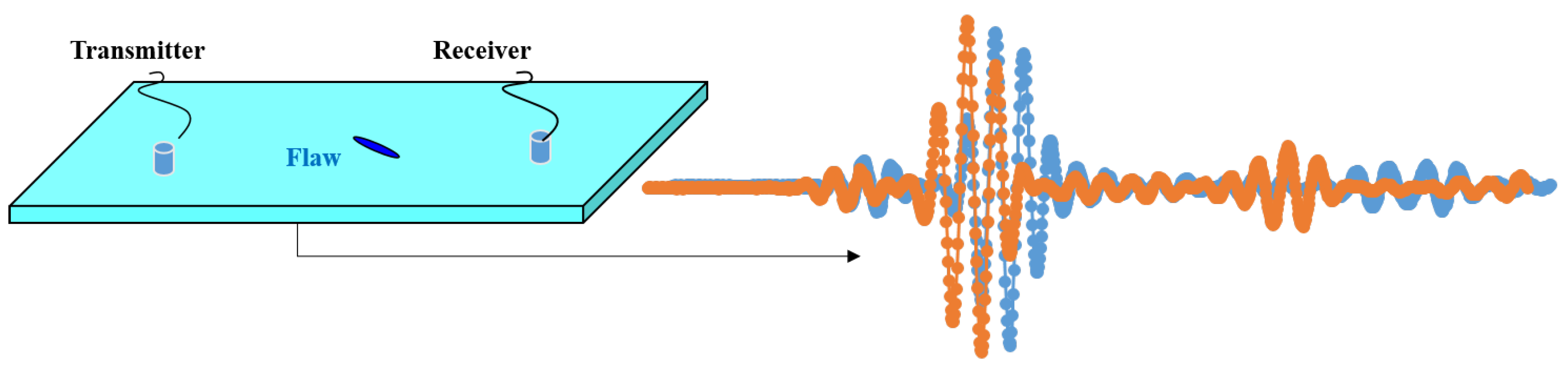
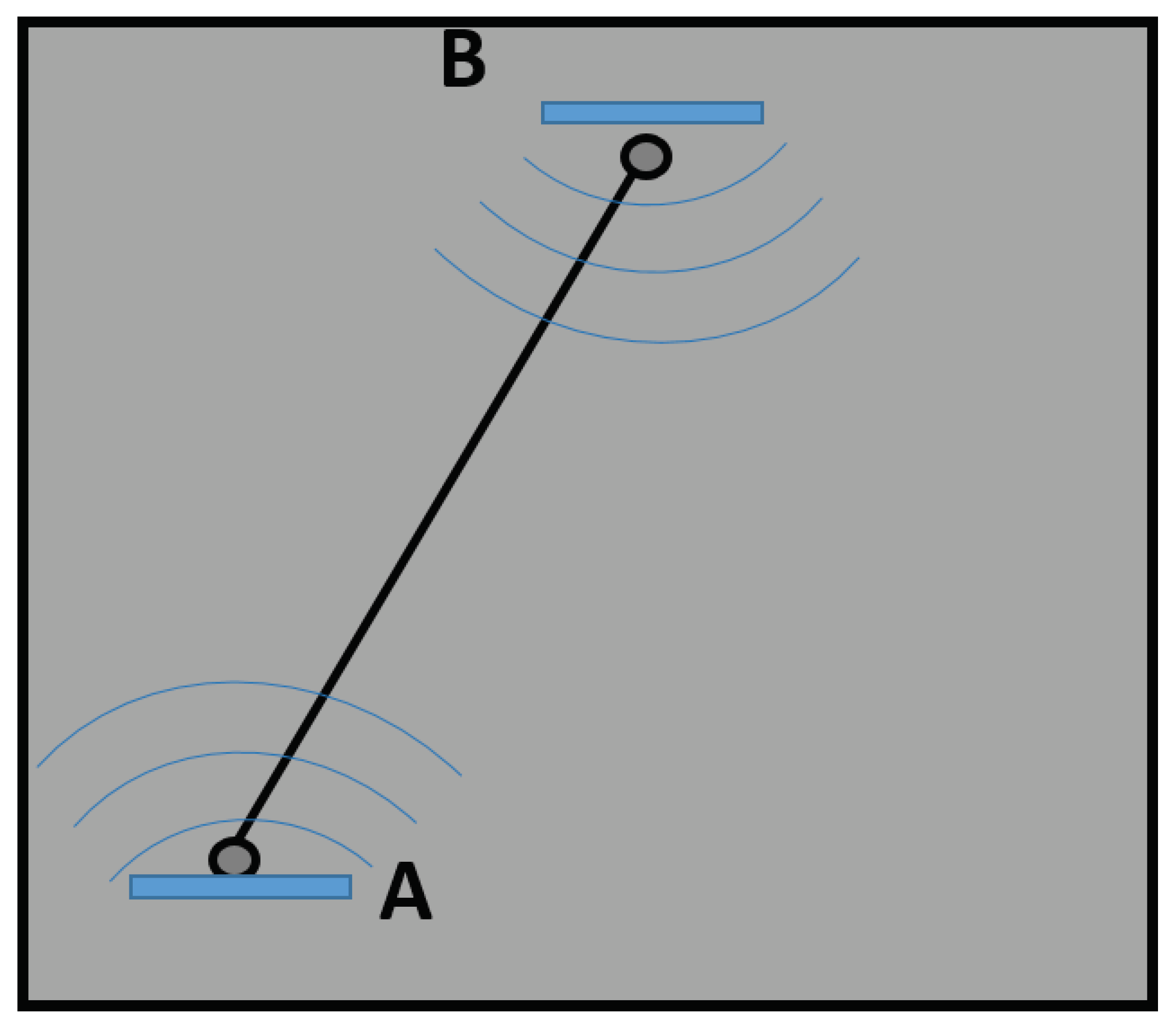
2.1. Flaw Detection Using Direct Propagating Waves

The detection and localization procedure adopted here requires the ultrasonic interrogation in “pitch–catch” mode in different operative conditions where the main activities involved can be grouped in:
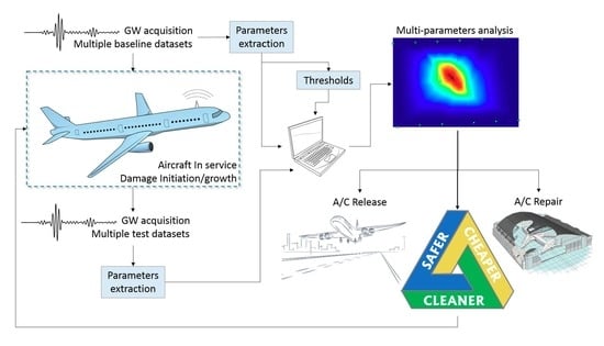
  • data acquisition, where the guided waves are recorded during aircraft parking according to the interrogation mode and stored for analysis;
  • data processing, which deals with the analysis of stored data to extract features possibly affected by the damage (signal response);
  • decision-making process, where the minimum metric associated to a damage with a reasonable confidence is established; and
  • damage reconstruction, which deals with all algorithms aimed at a certain diagnosis, no matter what is the level of the estimation.
Data acquisition and data processing are mostly related to the wave propagation behavior while the decision and reconstruction process is strongly related to the reconstruction algorithm adopted. Discussion about data acquisition is here limited to the description of the measurement setup. However, it is worth noting that the critical issue is the correct sampling of the guided waves related to the acquisition and analog to digital (receivers) and digital to analog (transmitter) conversion. In fact, a poor resolution of time histories reduces the system capabilities. The second item is related to several signal processing techniques to establish characteristic features of propagating wave which reveal the interaction with damage [29]. Instead, the latter items are crucial to select all useful data among those processed and to correctly relate the signal responses to damage features (e.g., occurrence, position, severity, dimension), as described hereinafter.

2.2. Ultrasonic Metrics

For the sake of the simplicity, it can be asserted that the propagation is always affected while a detectable damage is encountered. However, non-isotropic media are quite complex waveguides [13,30] making relating time histories caught in a few single sensing points to propagation, interaction with, and scattering from such a hidden flaw challenging. As highlighted in Figure 1 for a pitch–catch approach, the acquired signals are merely a synthesis of the wave propagation, which is reflected in the time history of the high frequency vibration affecting the receiver. Ultrasonic propagation needs the analysis of specific features (signal responses according to [22]) likely affected by unforeseen failure. Data analysis from rough signals is a key step for operating an identification system properly. The appropriate signal processing technique extracts features from the sensor array and translates the information gathered from single points into a diagnosis including location and/or severity of damage [31].
In fact, the accuracy and precision of a GUWs-based damage identification approach depends on the signals captured by several sensors and it is largely subject to their processing and interpretation. Efficient data processing while using limited resources is demanded to catch crucial yet concise features from raw signals which are expected to further provide the damage assessment. While the latter demand deals with the algorithms able to relate signal responses to damage parameters, such parameters have to be correctly addressed. Several signal processing techniques can be exploited in relation to the wave feature selected. Such selection depends primarily upon the type of damage to investigate while interrogating the structure. An impact induced damage can indeed be idealized as a complex discontinuity distributed through the thickness changing the waveguide characteristics [32]. Lamb waves are quite dispersive at certain frequencies and the interaction with local damage can lead to a different arrival time with respect to pristine propagation. The group velocity is strongly affected by those damages which modify the waveguide, while thickness frequency response shows a certain gradient. The group velocity results directly from the Time of Flight (ToF) estimating the characteristic time of the sensed ( t ¯ s ) and excited ( t ¯ e ) waves, respectively.
T o F = t ¯ s t ¯ e
Due to the dispersion restriction, the combination of wave modes, interrogation frequency and thickness variation strongly affects the detectability varying the time of flight efficiency. Otherwise, a discontinuity in a waveguide can be modeled as an abrupt change of the local mechanical impedance [33], where the energy propagating in the media is scattered. Transmitted and received portions of the energy content of the propagating wave can be monitored using the pitch–catch approach where such a Transmission Factor (TF) identifies the hidden flaw. To obtain an interrogation-independent metric, the transmission factor is here defined as the ratio between an energy parameter E ¯ of the sensed and the excited signal, respectively:
T F = E ¯ s E ¯ e
Both energy parameter and characteristic time can be computed by means of Short Time Fourier Transform (STFT) of the digitized signal (see Equation (4))
S T F T x t t , ω = X ω , t = t + X t ω t τ e j ω t
where x ( t ) is the discrete signal and ω ( t ) is the window function, chosen here as Hanning function, used to select a subset of samples to be further processed with Fourier transform using a certain overlap [34]. This function ensures low aliasing a with slightly lower resolution. The amplitude of the Power Spectral Density P S D calculated with Equation (4) identifies the energy content of the selected Lamb wave mode exploited in Equation (3) and the characteristic time exploited in Equation (2). It is worth noting that the ratio between excited and sensed wave in Equation (3) allows neglecting every dependence upon discrete transformation included in Equation (4) (e.g., ω ( t ) and τ ). For arrival time, the STFT approach is usually preferred because of the double feature obtained preventing further processing for cross correlation analysis which has been proven to lead to quite close results.
When the damage occurs, the wave transmitted over the flaw results from a complex interaction which is characterized by the scattering of the incident guided mode into propagating and non-propagating evanescent modes [35], including mode conversion in the case of multi-modal waves (e.g., Lamb waves). In fact, to account for every change in the complex wave packet sensed rather than the interrogating mode selected, the parameter should account for the entire diagnostic signal. For the latter demand, the wave energy E is a key feature and it can be computed in its generalized version [36] analyzing the time or spectral domain following Equation (5).
E = + x t 2 = + X ω 2
Because the primary measurements acquired are time limited signals, it is worth noting that the time analysis is adopted to maximize the accuracy. In addition, sensing the wave from t 0 (trigger time) to t f i n (observation time), the dependences upon time limited analysis can be neglected using damage indicators as comparative features.
The damage-related metric can be finally computed following Equation (6), where the extracted feature f (scalar quantity), chosen among Equations (2), (3) and (5) or others, is evaluated on pristine f B and currently operating f C structures separately to assess the damage indicator.
D I ( f ) = f C f B f B

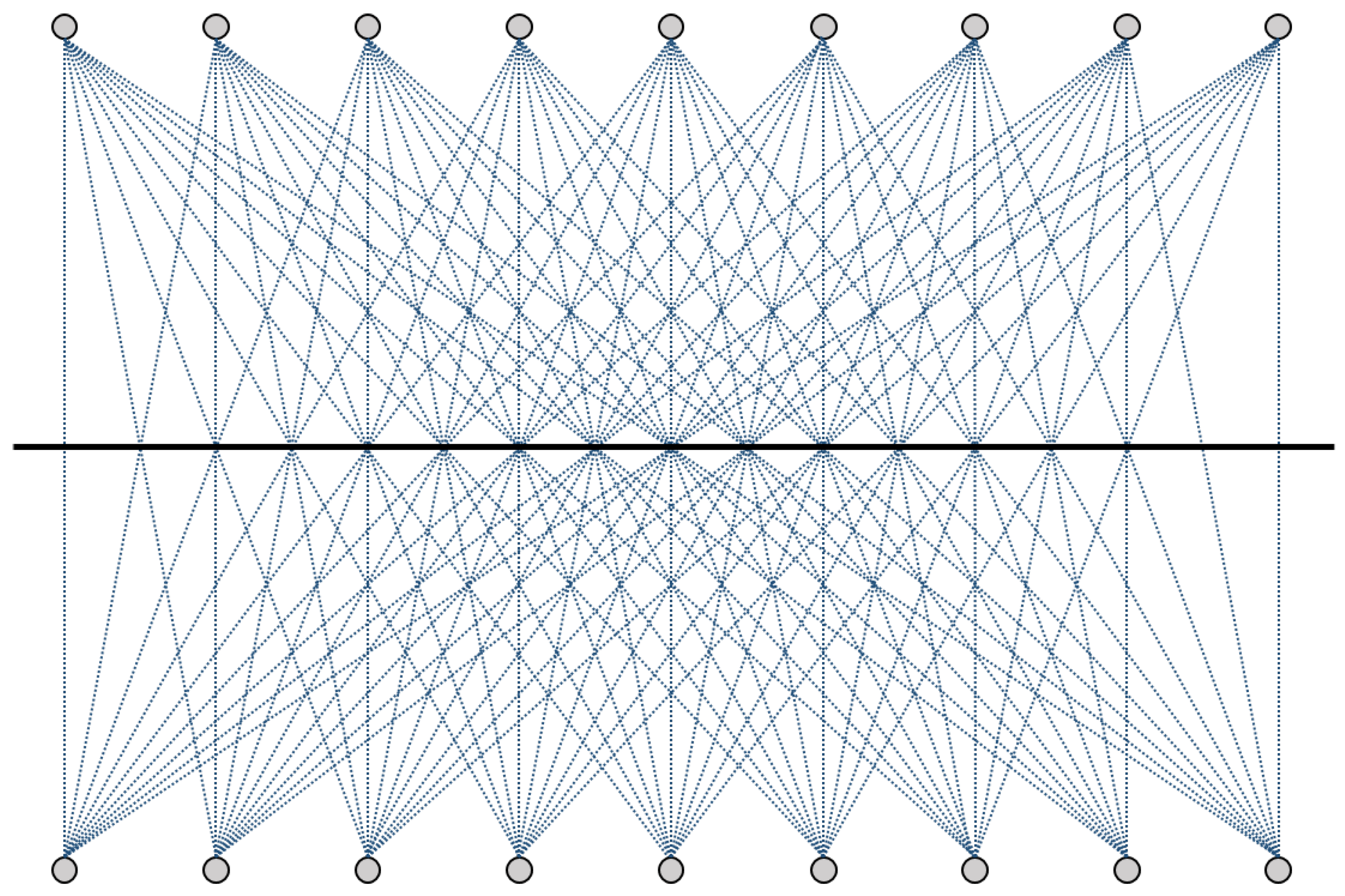
2.3. Multi-Path Reconstruction Principles

When the features are extracted from wave signals, a key procedure regards the decision making approach, where the changes detected in the guided waves are defined sufficient enough to identify any damage. The autonomous identification of failure is itself the determination of a threshold level efficiently warning the presence of damage. Hence, a non-arbitrary decision procedure which does not rely on the expertise of any operator is crucial. The results below the decision level are then censured and, when available, those above the threshold are analyzed to further locate and characterize the failure.
In detail, the detection approach is based on a multi-path analysis in which lines of sight between every actuator–receiver pair are exploited to obtain a set of independent interrogations, whose post processing returns the several features described. Using a cluster with a limited number of sources, it is indeed possible to define a discrete number of paths affected by damage emerging at the surrounding area [37]. The same approach can be used also in complex structures as depicted in Figure 2 where a double-line array of sensors is adopted to monitor the stringer in a stiffened structure. If one damage indicator exceeds the threshold, the path is indeed affected by damage and classified as damaged by the system. A few selected paths are classified among all possible propagation paths using the decisional step. Those ones are used for the localization presented in Section 2.5. It is supposed that paths crossing the damages area are affected by stiffness variation which results in a different vibration response reflected within the signals. Otherwise, paths crossing far from damaged area are not affected because no stiffness variation is present. Consequently, the damage index theoretically vanishes when signals are sensed on the same structural condition. However, repeating measurements leads to slightly different results with nonzero value of DI, [38], demanding a specific decision tool using prediction techniques to define the minimum indicator value warning the presence of a damage.

2.4. Decision-Making Approach

The decision-making procedure can be statistically addressed; damage detection is achieved when measurements return damage metrics exceeding the threshold according to a certain confidence level. In fact, decisional phase combines knowledge and uncertainties due to random and systematic variability in measurements. To prevent the misinterpretation of those changes revealed by the dynamic response of the structure, statistics allows the classification of the wave parameters ensuring a certain degree of confidence. Various approaches are available in the literature to define a discriminating threshold by unsupervised learning mode and using central statistics [39] or outliers analysis [24,40,41,42]. The main issue is to ensure that the extreme values are properly estimated because there the data from pristine and altered condition may be very close. Furthermore, threshold determination can be obtained by supervised approach using previous observations or simulations. In many investigations, disturbances resulting from inputs and environmental variation are introduced numerically to achieve the threshold level estimated in the next measurements [26,43,44] at the cost of analysis which are often too much intensive.
To account such a variability due to the non-repeatability and noise of measurements, a prediction interval can be more simply estimated according to the definition of a normal distribution. In this case, an appropriate hypothesis test is required to classify the feature distribution while no damage is indeed present in the structure. The damage indicator that returns from that analysis measures the noise level instead of the damage level. Then, the Gauss bound is estimated to discern the damaged condition from the noise. When the damage is present, the feature is expected to be above the estimated upper bound level. In this context, an effective discrimination of sensitive signals can be reached even with few samples and less effort using parametric statistics such as a Kolmogorov–Smirnov test [45]. An example of such application is successfully presented in Figure 3 where the energy based metric is parametrically defined together with the threshold level, I t h :
I t h = μ + k · σ
where μ is the estimated mean value and σ is the estimated standard deviation of the noise. The k factor defines the bounds of the prediction interval and it depends on the significance level chosen in accordance with normal distribution. With the probability of 1 α , every sample x i of the population X (i.e., DS population) is in the range defined by statistical bounds. For the sake of the clarity, for a normally distributed noise, the threshold level fixed as μ + 1.96 · σ provides a 97.5% prediction interval. If the damage indicator lies below that value, there is 97.5 % confidence in stating that no damage is indeed occurring. Likewise, a damage index higher than that limit returns a 97.5 % confidence in stating that the damage is present.
This prediction analysis returns a statistically meaningful threshold only when a certain variability is present in the signal response. However, when a discrete transformation is computed (see Equation (4)), signal processing of experimental data demonstrates that uncertainties are hidden by the time–frequency discretization; the metric is classified in larger ranges whose extremes (discrete metric) prevent the statistical analysis of such data. To overcome this lack of applicability, the Acoustic Reciprocity Theorem is proposed in an unsupervised learning mode to discern noise from signal response when any variability is not identified from statistics. The B e t t i reciprocal theorem [2] applied to ultrasonic fields suggests that the signal response related to the direct wave should not be dependent upon the direction of wave propagation in pristine condition. Hence, exciting Lamb waves with a transducer located in A and sensing the wave propagation with the sensor located in B (see Figure 4), the system should return some features that are equal to those extracted from signal recorded by a sensor located in A while exciting propagation with a transducer located in B.
Measurements and data processing show that this principle is not satisfied even when any damage is not indeed present in the structure [15,38]. In addition, this consideration is applied to different transmitter–sensor couples so that the lack of agreement is still present when a nearly repeatability of extracted features is obtained. Thus, the reciprocity mismatch is considered here due to such uncertainties affecting damage detection. It simply provides the decision value as the maximum difference between the same feature observed along the two propagation directions.

2.5. Reconstruction Algorithm

The identification of damage is the first diagnostic output achievable with a SHM system, warning the presence of a damage. With a statistical correlation, the signal response can be related to the severity of damage [22], but it does not provide any information about its location. Using several signal processing techniques, the detection approach described in Section 2.4 aims to select those paths affected by such a damage. The last result can be used to locate the damage using an opportune reconstruction scheme aimed to assess the risk to have a damage in a specific location. Since the identification is provided with the threshold definition, the location of damage is estimated as the location with the highest risk. The information contained after data processing is related to the paths and it is necessary to get that knowledge on the structure via developing an image depicting the position of damage. Many image techniques to investigate the region surrounded by an array of transducers have been developed in the past years in this field as reported in [46]. One of such techniques is the guided wave based tomography where certain features of a wave mode or of a sensed signal are used as input to create an image of the area for damage detection. Discretized the structure to be monitored in finite elements (see Figure 5), it is possible to define two different types of mesh: (i) the structural mesh, where the health information is desired; and (ii) the SHM mesh, where that information is primarily known. Depending on the relation between them, it is possible to broadly group several techniques in:
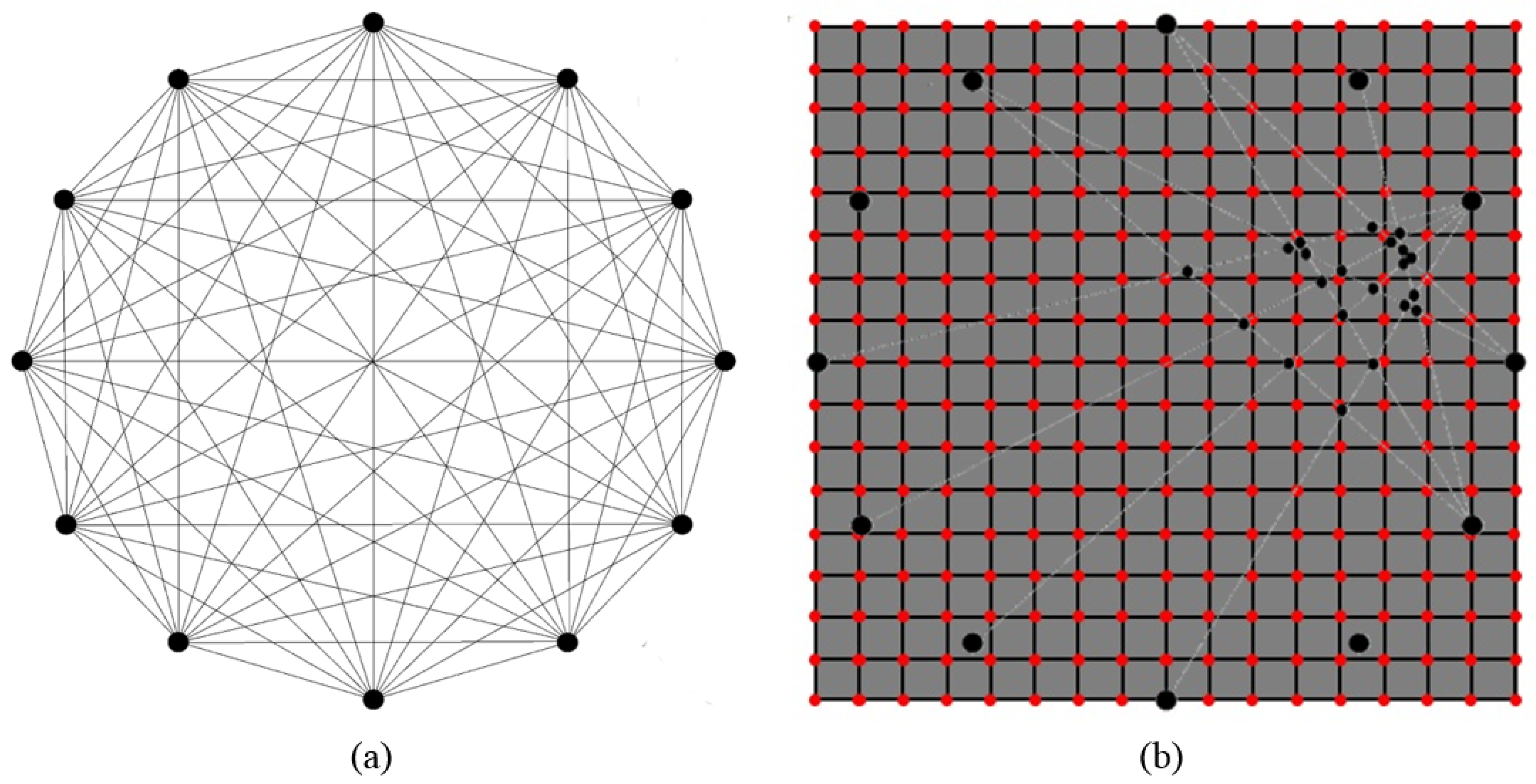
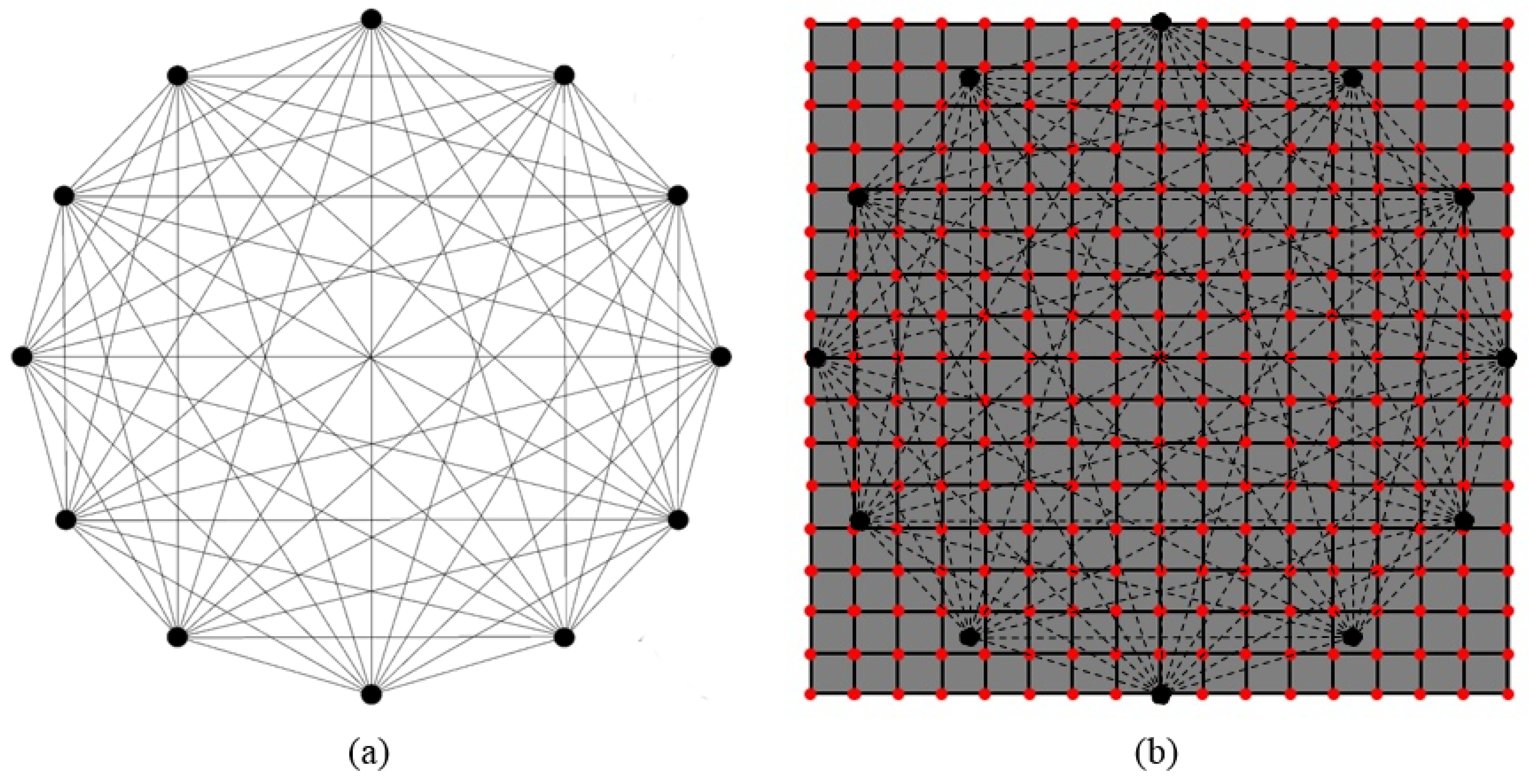
  • mesh-based approaches, where SHM data are directly obtained on the structural mesh (i.e., the SHM mesh corresponds to the structural mesh [18]); and
  • meshless approaches, where the SHM data are obtained in points not previously known and interpolated on the structural mesh (i.e., the SHM mesh does not match with the structural mesh [47]).
The first approach usually requires a heavy computational effort accounting for each point the effect of all possible paths resorting to a decreasing probability far from their line of sight [16].
To reduce the efforts demanded by a mesh-based probabilistic formulation, the effect of selected paths is here considered in a different way. From their intersection, few emerging points create the SHM mesh where structural condition is parameterized according the average value of DI at intersecting lines of sight. The coordinates of such resulting nodes, whose weight is the resulting DI, can be passed on to an algorithm which estimates the the impact point through such a tomographic representation of damaged area. Several image processing techniques can be exploited to portray the health status from scattered data points to the structural mesh and they can broadly classified as:
  • discrete approach;
  • spatial interpolation; and
  • nodal density.
With the former approach, scattered data formally constitute a discrete system. The damage location is estimated considering the centroid of the SHM mesh where he weight of every discrete point is mainly the DI which returns at the emerging node. The barycentric information is estimated first via weighted averaging algorithms. Accordingly, the damage location is then defined as the point C G = ( x C G ; y C G ) in the Cartesian reference. The geometric extrapolation of the coordinates ( C G G ) is carried out as follows:
x G = i = 1 n x i f i i = 1 n f i , y G = i = 1 n y i f i i = 1 n f i
while the arithmetic coordinates ( C G A ) are given by:
x G = i = 1 n x i · f i i = 1 n f i , y G = i = 1 n y i · f i i = 1 n f i
where f i is the weight of the ith node, namely the damage indicator.
Otherwise, considering that each node of the SHM mesh contains structural information about the surrounding area according to the emerging damage indicators, the damage can be located fitting a surface on the scattered data. The scattered data are interpolated to smooth the surface on to the supporting (structural) mesh which returns the risk to having a damage in a specific location. The highest risk is thus associated to the impact position. Likewise, the latter approach enables the density of the SHM mesh as the key feature to be interpolated and provides the damage risk. It mainly accounts that the greater is the number of points, the higher the probability is to have damage in the concerned area. Returning a sort of damage risk map, the last two approaches provide such a global reconstruction rather than merely the localization of hidden diagnosed with the first approach. In both cases, the reconstruction returns a rapidly decreasing risk moving away from the SHM mesh whose main criteria are itemized below:
  • The damage risk is estimated on the area enclosed by the sensors which are employed to set boundary conditions for the interpolation.
  • The data below the threshold do not affect the interpolation because are censured by the decision-making approach.
  • Every isolated path which is not intersecting at least another path does not affect the localization.
  • The peak of smoothed function returns the damage position whose coordinates are used to estimate the impact location.
It is worth noting that a node of the SHM mesh affects only the surrounding area according to the specific scheme adopted for the interpolation. Here, the imaging is carried out using spline-based algorithm, typically suited for image processing when few data are supposed to be available.
In the next section, several results are described. A first analysis based on numerical data is presented to demonstrate and overcome a few shortcomings of the proposed methodology. Interpolation is improved weighting the effect of DIs merging the nodal density approach to the images obtained with a single parameter interpolation. The final improvement is obtained resorting to a normalization and further data fusion to obtain the multi-path and multi-parameter approach called M P 2 and based on meshless reconstruction. The results are finally compared with those obtained using literature mesh based “benchmarks” improved by resorting to the same multi-parameter approach. After validating the reliability and efficiency of the M P 2 system, real scale structures are monitored with the M P 2 approach to detect and localize both delamination-like structures and stiffener disbondings.

3. Results

3.1. Setup

The structural health monitoring based on guided wave propagation is here operated through several steps, which are the same whether simulations or experiments are considered. The structure is simulated/integrated with several PZTs to constitute the active diagnostic cluster of sensors where multiple datasets are then extracted. To get all data, the multipath guided wave propagation is activated first on the pristine structure and then on the current (damaged) structure. The currently operating structure is obtained by introducing a barely visible damage to simulate the airplane-in-service when cracks can initiate and propagate. The data are thus post processed with the comparative multi-parameter analysis and the damage is reconstructed where any damage indicator is found to overcome the threshold. A 4.5 sine-cycles windowed burst excited at low-ultrasound frequencies is adopted as diagnostic wave to mostly excite the A 0 mode and extract the described features. That mode is selected as interrogation mode instead of S 0 or S H 0 modes because more tuned with the type of sensors employed at low ultrasound frequencies. The sketch of the processes followed during experiments is reported in Figure 6 where the modeling of Structure, PZTs and damage is highlighted with multiple option according to how the datasets are extracted. Those are where the experiments and simulation are indeed different. To achieve a correlation between measurements and simulation, the methodology already developed for this type of damage and validated in [32] is successfully adopted.

3.2. Validation of Multi-Parameter Analysis

While exciting low ultrasound, only the fundamental Lamb wave modes ( A 0 (antisymmetric) and S 0 (symmetric)) are excited. Whereas antisymmetric mode appears more tuned, group velocity and transmission factor of the A 0 mode are typically evaluated by processing recorded signals. Instead, the energy content integrated over time allows accounting for the effect of the damage on several propagating modes. Comparing signals, only a few paths among those defined by all possible sensors pairs are selected as those affected by the damage. Summarizing preliminary results for the sake of conciseness, it is worth noting that impact induced damage can be typically identified and localized using the approach proposed in the previous section even where a minimum number of emerging nodes results from decision-making approach. For several features, only the DIs higher than the respective threshold currently suggest the presence of the damage and the impact location is predicted with a negligible error compared to the size of the damage. Furthermore, the impact location predicted with discrete approach falls exactly in the area with greater probability of damage appearance.
Although a very simple, faster (compared with other image reconstruction algorithms) and effective approach has been obtained including discrete analysis and spatial interpolation to improve hidden flaw localization after the decision-making approach, few criticality aspects have been detected with the aid of numerical simulations as well.
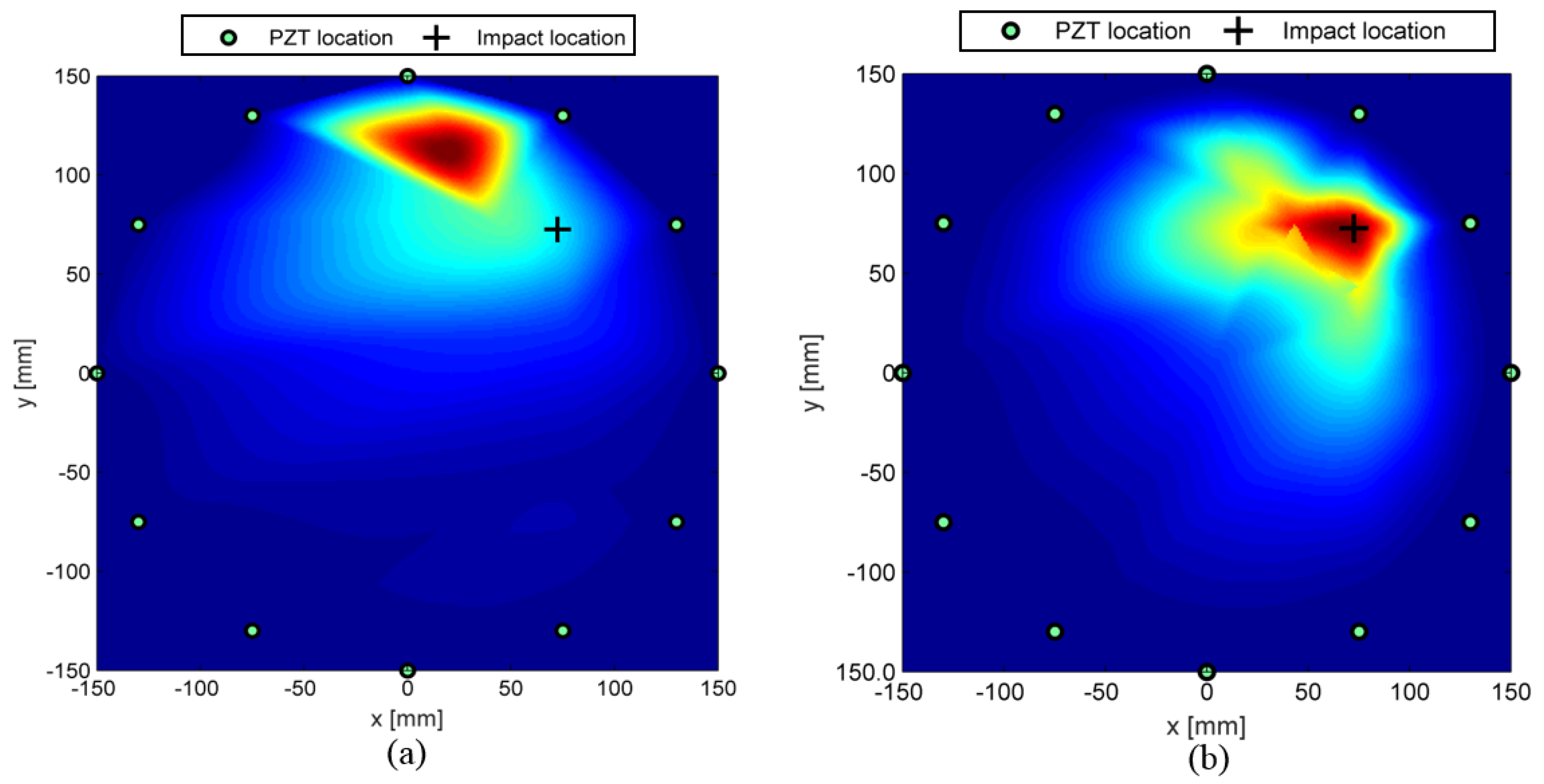
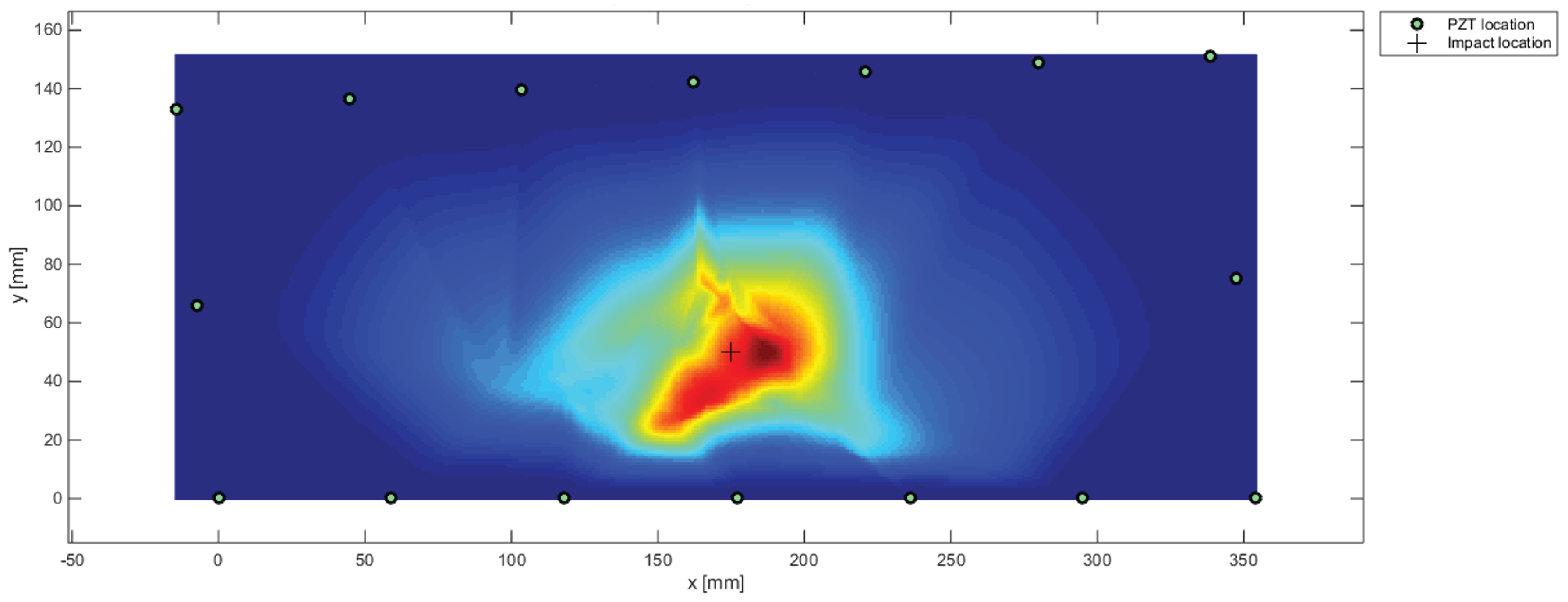
  • Phantom damages: Several spots in the image may suggest damage where no failure is present. This event happens when few nodes in the SHM mesh are emerging far from the damage due to the intersection of most affected paths among those selected. The high DI level associated to those paths induces a high risk to a single node which is indeed far from damage location.
  • Feature sensitivity: Due to the complex behavior of wave propagation and the statistical decision-making approach, a few paths that should be affected by the damage show a response suggesting no change in the structure. Otherwise, relevant changes in signal response can be detected even when no such a damage affects the correspondent line of sight. This happens especially when time of flight associated with low dispersivity of A 0 mode is adopted to detect changes in the waveguide.
About the first item, it is worth noting that the most critical area (damage) corresponds always to the area with the largest number of neighboring nodes in the SHM mesh. This remark suggests to resort to nodal density as damage metric, i.e. the greater is the number of nodes, the higher is the risk to have damage in the neighboring area. Namely, an isolated spot with very high damage indicator may return false alarm. Conversely, the large number of emerging nodes with a damage indicator exceeding threshold returns the damage diagnosis with higher reliability.
The output of a numerical simulation is considered hereinafter to analyze such aspects and to establish a reliable solution to be further validated on real scale components. In detail, the structure considered is a 6 mm-thick bay of a tapered wing panel designed for a lower wing panel discretized resorting to 600 mm × 600 mm × 6 mm composite plate made of carbon-epoxy material typically adopted in the aeronautical sector on which 12 PZT disks made of soft material PIC 255 by Physik Instrumente are mounted and arranged in a circular network. The plate is laminated using unidirectional laminae with fibers along 0 (UD) and biaxial laminae with orientation 0 / 90 (B) and ± 45 (B45) which are stacked between 5 H a r n e s s (5H) external plies according to the stacking sequence [ 5 H / B 45 / U / B / U / B 45 / U / B ] s . The plies are discretized as single layers modeling the material properties reported in Table 1 and material orientation according to the defined layup.
The wave propagation is simulated by using equivalent single layer approach [13] and the damage is discretized decreasing the mechanical properties around the impact [32]. The noise is then mathematically introduced into the signals to simulate the decision-making approach. As anticipated above, Figure 7a shows that the phantom damages are located in a sparsely populated area. This evidence confirms the hypothesis about the critical role of the nodal density. Furthermore, it can be confirmed as a lack of the reconstruction technique appearing appearing even while resorting to simulations. The SHM mesh indeed consists of nodes emerging from the intersection of those paths affected by the damage occurrence according to the decision-making output. It may happen that two selected paths strongly affected by the hidden failure (i.e., they return a high damage indicator) intersect each other in an area far away from the real damage location. Thus, an isolated spot arises around that location, generating a lack of the reliability. To reduce such a false alarm in damage prediction, the density of the SHM mesh can be calculated for each node resorting to the distance between that node and the others as follows:
1 f i = j = 1 n ( x i x j ) 2 + ( y i y j ) 2 n 1 , i j and i , j = 1 , 2 , , n
where f i is the density parameter of the ith node and and n is the number of SHM nodes. Then, the parameter is normalized in order to do not affect the DI scale as follows:
f ¯ i = f i ( f i ) m a x , i = 1 , 2 , , n
Such a d e n s i f i c a t i o n factor is preferred here rather than a classic density definition because it allows addressing such a weight for each node: the higher is the inverse of the average distance obtained, the greater is the number of nodes in the surrounding area. Instead, to construct another image, a new damage index is formulated as:
D I i w = f ¯ i · D I i
where D I i is the damage index value assigned to the ith node after decision making phase. The D I i w is thus preferred because it incorporates the severity of damage ( D I i ) with the density of emerging nodes in the surrounding area ( f i ). The ability to eliminate phantom damages is depicted in Figure 7b, where any indecision in the damage reconstruction is overcome, without giving up the information about the gravity of damage. In this case, the probability of a false alarm due to the occurrence of phantom damage rapidly decreases.
The second item regards the sensitivity of the specific feature to a specific damage. Due to the wide range of variables involved (frequency, thickness, multimode, dispersion, damage scenarios, etc.), establishing the relation between a classified damage and the effectiveness of a single feature is often complex. Every feature extracted from wave modes has its own detection capability for a specific damage considered. Generally, damage indicators based on wave energy content analysis in time domain are quite effective for detection and localization especially while accounting all modes, echoes and reflections affected by the failure. On the other hand, when the energy based feature accounts the entire wave signal, it strongly reflects the noise and the threshold, which is usually very high, and may censure also useful data. The same discussion can be pointed out for the transmission factor based damage index. Although it is likewise effective, it is affected by those echoes and waves appearing in the signal with the same frequency which introduce distortion in the wave spectrum. Otherwise, a different discussion lies in the time of flight parameter because it is connected to dispersive behavior of selected wave mode which strongly depends upon the frequency thickness. This feature indeed appears effective while decreasing the thickness of the structure and the efficiency is strongly reduced with thicker solids. In addition, its efficiency is related to the ratio between damage dimension and path length; the local effect of hidden failure is indeed mitigated by the entire propagation path between the couple of sensors.
Among those explained, the most striking result deals with such dispersive behavior, which affects the localization of damage using ToF single-parameter representation. Figure 8a shows the result obtained with the T o F damage index This lack of agreement while processing wave velocity is due to the fact that the A 0 mode shows low dispersive behavior around 60 kHz, the frequency chosen to optimize the signal response of the antisymmetric mode. Emerging even when propagating waves are simulated, such result is mostly due to the parameter selection rather than to uncertainties in measurements.
However, a SHM system should be oriented to find the more reliable and general purpose identification rather than the more reliable feature according to the specific case. In addition, an autonomous decision-making approach does not allow improving results by changing the decision level. Decisional procedure indeed affects and tightly correlates probability of false alarm and probability of detection. When defined the system target, the probability of detection (POD) is directly connected with safety and the operative costs due to the downtime decreases according with the probability of false alarm (PFA) [27]. Thus, while increasing the threshold, the PFA decreases (desirable) and the probability of missed detection increases, which means a decreasing POD (undesirable). Otherwise, the system can be enhanced by improving the system response. Several features parameters can be weighted and combined (data fusion) after decision-making to increase the robustness of the system versus the damage characteristics. Although probabilistic reconstruction is a consolidated approach for GUWs-based damage detection [16], there are few studies in which resulting reconstruction images for the same structural state are fused to improve damage localization and background noise [20]. The data fusion here is carried out resorting to the following steps:
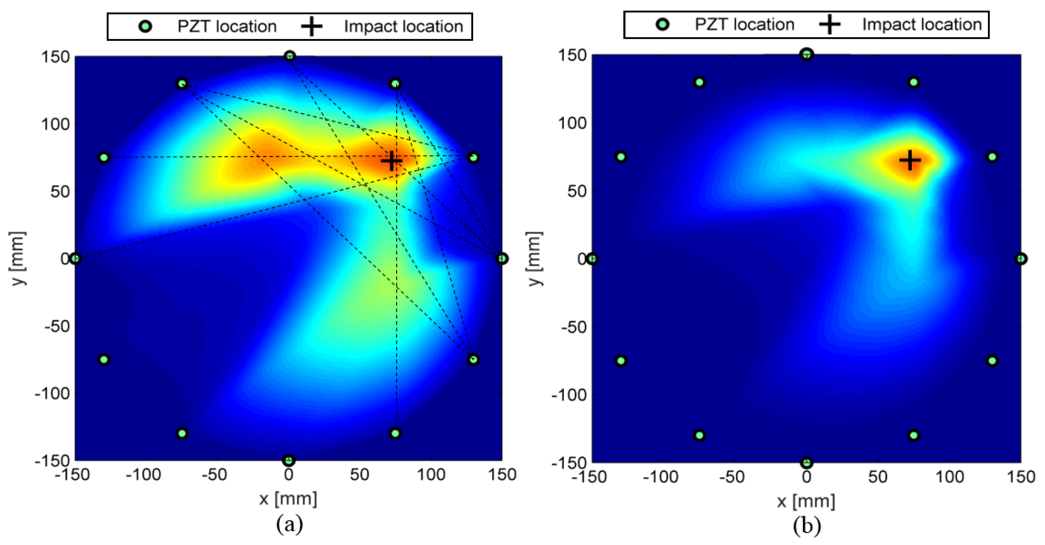
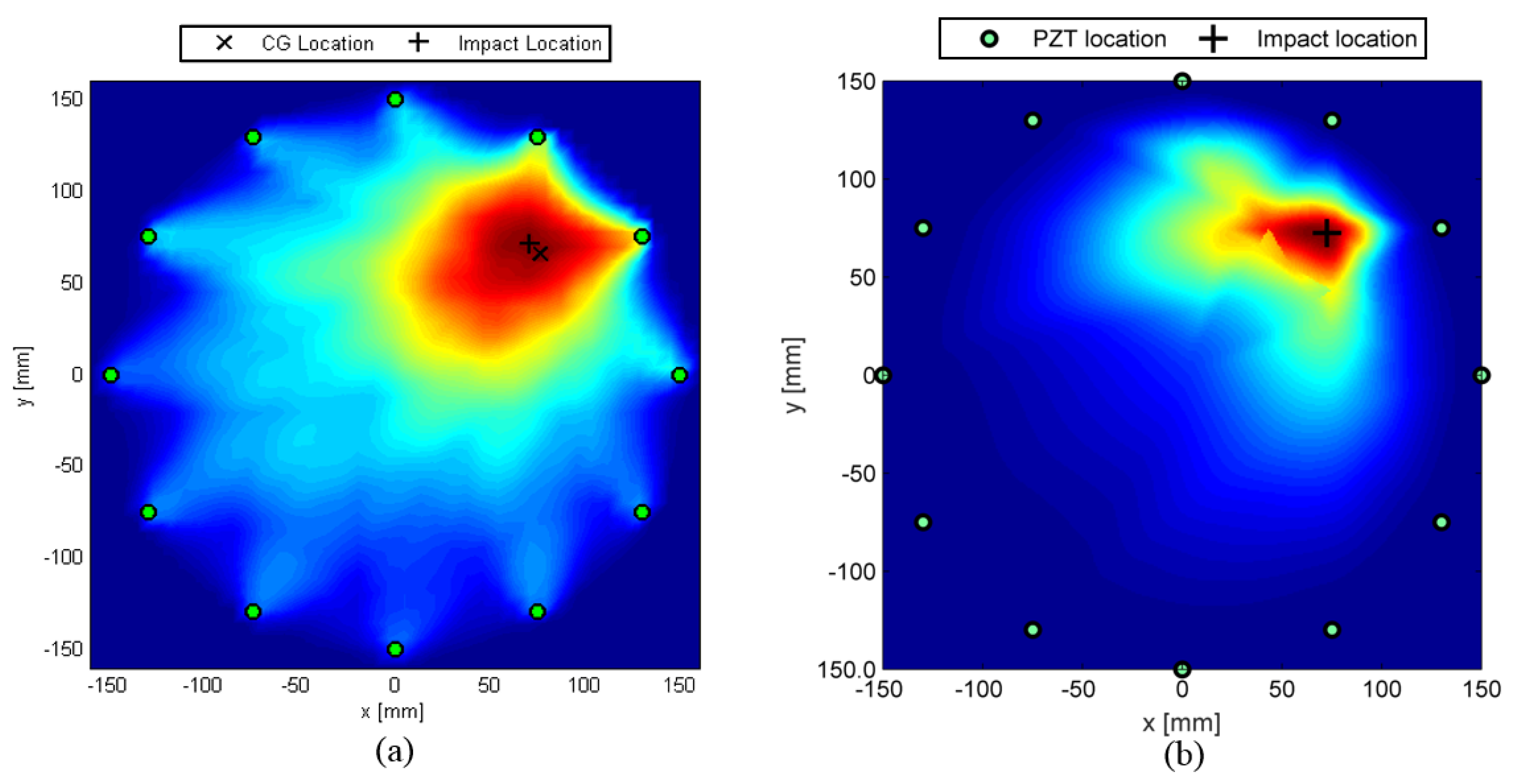
  • (i) weighting procedure according to Equation (12) for each parameter extracted from traveling waves and selected by decision-making step;
  • (ii) interpolation of damage according to each feature on the structural mesh (single parameter approach);
  • (iii) normalization of data obtained on that mesh; and
  • (iv) data fusion for the multi-parameter representation of damage.
The result obtained with data fusion of normalized weighted DIs is depicted in Figure 8 where the misleading interpretation of the ToF based reconstruction (Figure 8a) is clearly smoothed by introducing the multi-parameter approach (Figure 8b) including all of the three features considered.
To establish the effectiveness of the M P 2 meshless methodology, the results obtained are compared with a classic mesh-based approach where the damage index is evaluated in the same way for every path depicted in Figure 9a. Then, the damage probability index ( D P I ) is calculated in every point of structural mesh shown in Figure 9b resorting to a decreasing probability function based on a nonlinear definition of a distance Index ( d I ) , which establishes the effect of the path on its surrounding area. The effect induced by the ith path to the specific point P of the structural mesh is addressed as follows:
D P I i ( P ) = d I i ( P ) · D I i
where D I i is the damage index of ith path and d I i ( P ) is the distance index between that path and point P calculated according to enable a specific decreasing probability. To obtain the classic elliptical reconstruction [18], for each point P, the distance δ i ( P ) is calculated from the distances between that node and the sensors connected by the ith path. The distance index is then evaluated following Equation (14) where β is a scale parameter (i.e., it defines the farther influence of a path) to improve the reconstruction after being calibrated on a well-known condition. Finally, the D P I of the point P is evaluated accounting for the effects of every selected path induced on the point P and normalizing such overall value for further data fusion according to the multi-parameter approach.
d I i ( P ) = β δ i ( P ) β 1 , δ i ( P ) β d I i ( P ) = 0 , δ i ( P ) β
The results obtained with mesh based and meshless multi-parameter ( M P 2 ) approach are reported in Figure 10. Figure 10a shows a mesh-based reconstruction and returns damage identification and localization without uncertainties. Figure 10b shows the reconstruction of the meshless-based diagnosis, where the density weight is able to restrict the localization around the damage location. From the comparison, it is worth noting that a similar reasonable result can be obtained with the meshless approach with less computational cost needed.

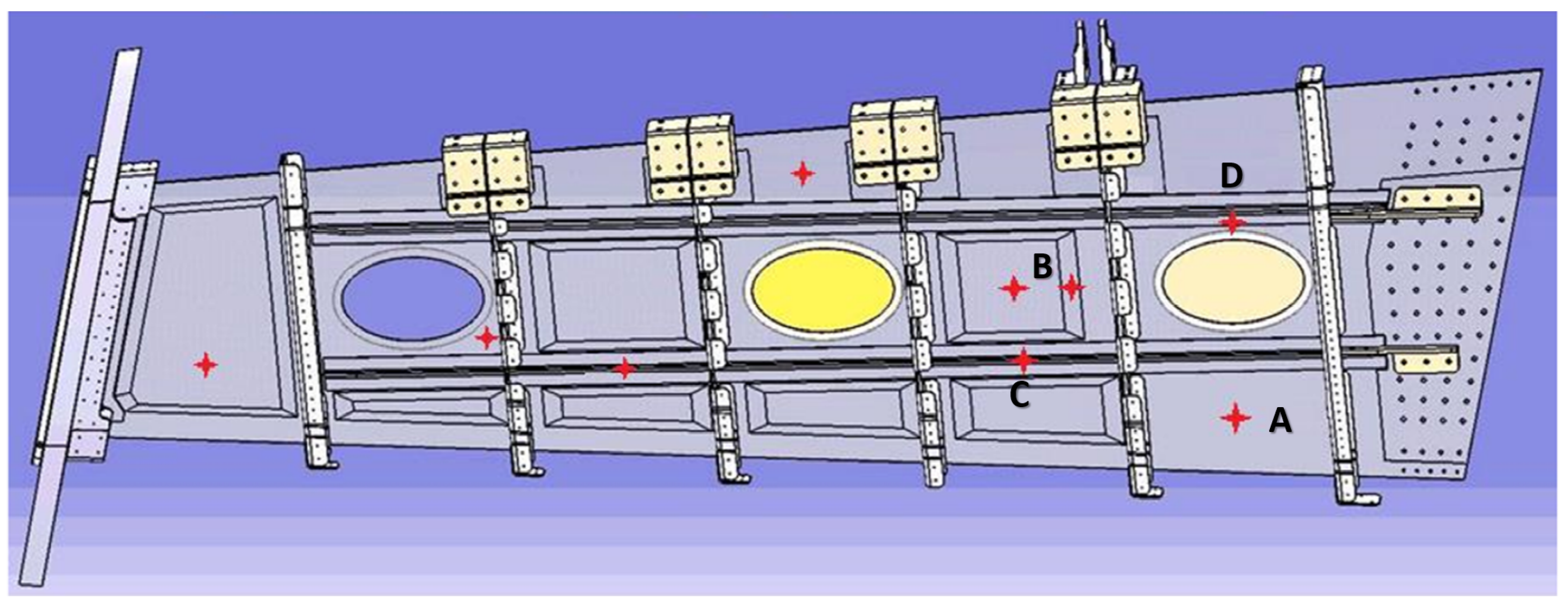
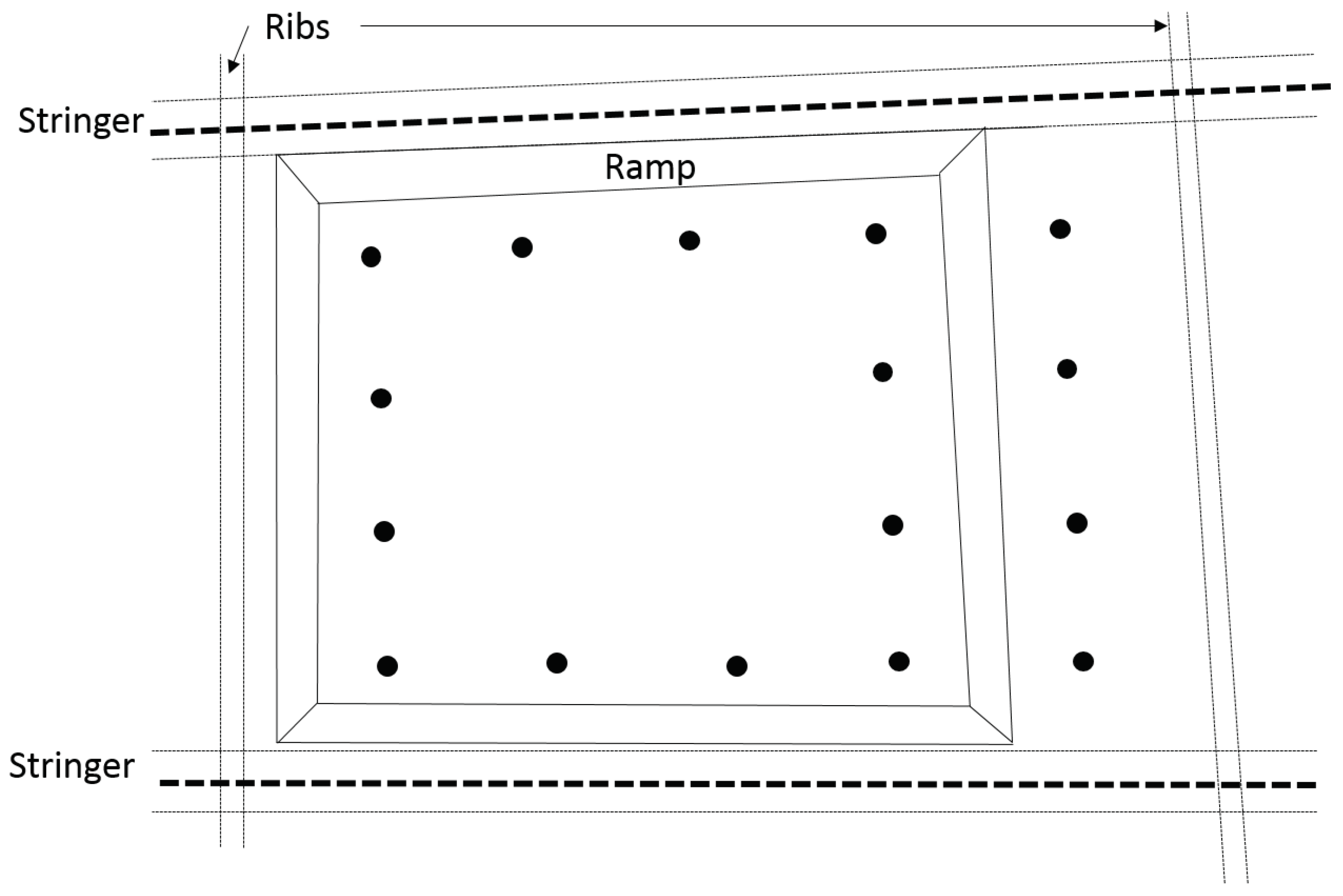
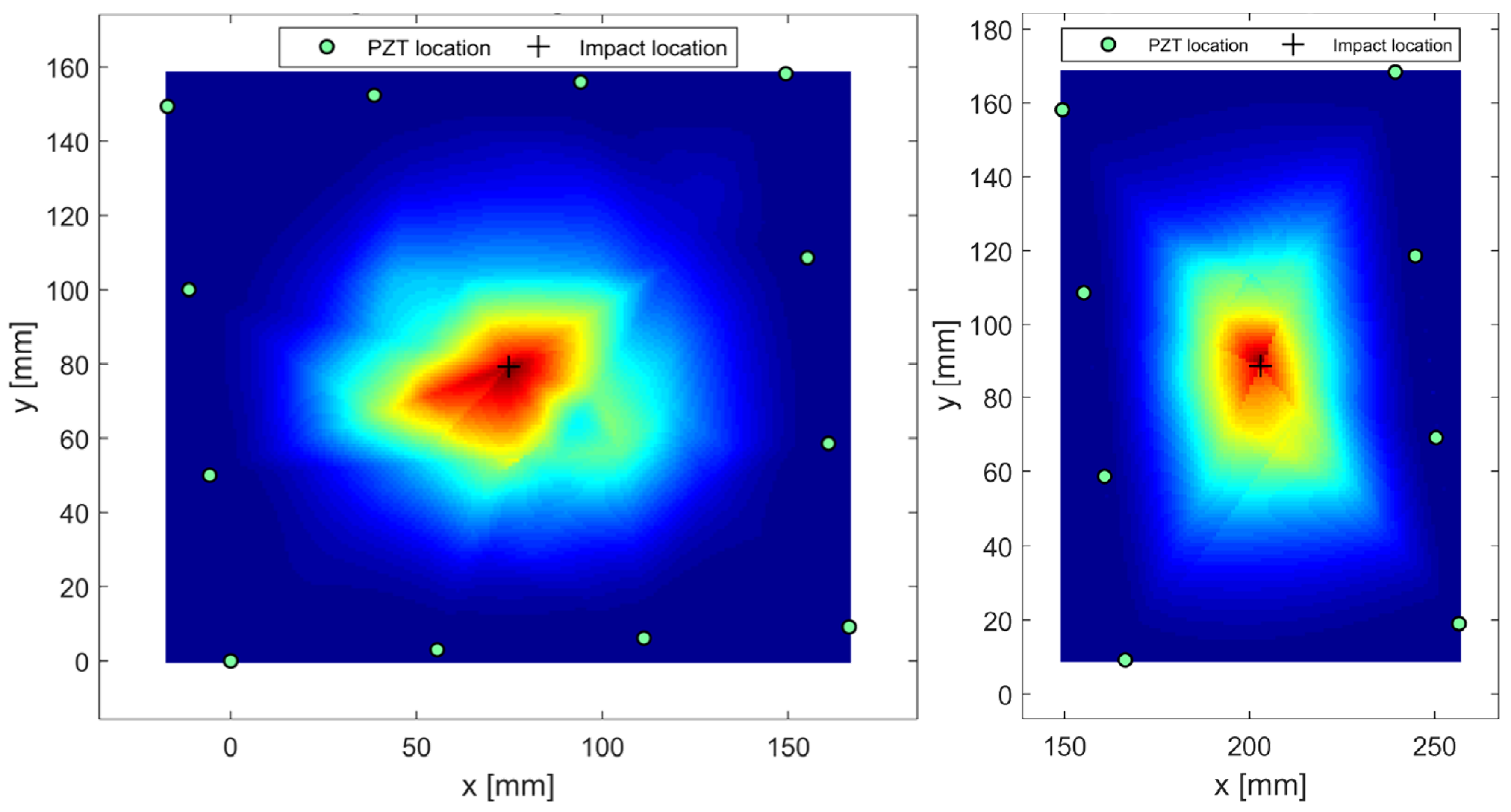
3.3. Delamination Detection in Complex Structures

The M P 2 methodology described in the previous section is employed and validated on real scale structures designed for the outer wing box of a commercial aircraft (see Figure 11). For the sake of the conciseness, the effects of several improvements in the M P 2 system are not further discussed by using measurement datasets. The results obtained through numerical simulations are even confirmed by the experiments, where the multi parameter approach is able to enhance the detectability of the multipath analysis. About the structure, the same material and similar thicknesses of the composite plate discretized in the virtual environment are designed for the wing component. In addition, several stringers are inserted for stiffening the thin walled structure according to the actual aerospace advanced structural design [2].
Before monitoring the structure, the wave behavior of the A 0 mode is investigated on a flat area of the lower wing panel where a similar thickness (about 6 mm) and stacking sequence is present ( [ 5 H / B 45 / U / B / U / B 45 / U / B ] s ). The dispersion curves depicted in Figure 12a confirm the low dispersivity discussed in the previous section along principal direction of propagation. Furthermore, there is n strong dependence of the group velocity upon the direction of propagation. This result is mostly due to the thick plate and the complex stacking sequence which is inclined to a quasi-isotropic configuration. Otherwise, the tuning of the anti-symmetric mode is strongly dependent upon the frequency of excitation showing the classic bend bell curve in Figure 12b.
The SHM system is expected to monitor critical components of the entire structure, including thin bays (delamination detection) and stiffened area (disbonding detection). Hence, several bays of the structure are sensorized with clusters of PZTs bonded on the inner surface to perform condition monitoring when the wing box is correctly assembled and mounted on the aircraft. The sensors distribution, for each group and for each bay, is defined according to: (i) the potential critical impact locations during lifetime; and (ii) the wave propagation directionality analysis. Figure 11 shows in detail the critical impact points selected which are reported on the inner side of the lower wing panel. The structure includes three different thicknesses zones and transition areas with an inhomogeneous distribution inside each bay with respect to the nominal value of 8.3 mm. The other identified thickness values are 12.5 mm below the T-shaped stringers, 10 mm in the left thin walled bay, and 6.4 mm in the remaining bays where the ramp is depicted. According to the described setup, the aircraft operative life is simulated through impact tests on the lower wing panel after wing-box assembly stage. The complex test article constraint system (when mounted on the wing-box) and the inhomogeneous distribution of thickness require impact energy calibration tests suggesting the energy level to obtain barely visible damages. The experimental calibrated energies found are:
  • 60 J for 6.4 mm thickness;
  • 90 J for 8.3 mm thickness; and
  • 100–110 J for 10 mm thickness.
After energy impact calibration, the baseline ultrasonic data are acquired and scheduled impacts are performed through drop weight test. Each impacted area reveals the presence of barely visible damages when inspected with nondestructive ultrasonic phased array tests which are adopted for detailed inspection in the aeronautical sector. Finally, the current ultrasonic data are acquired for further post processing.
Figure 13 shows one of the sensor clusters adopted to monitor delamination-like damages in flat thin walled composite. Several PZT transducers are located on the independent bay delimited by stringer, ribs and corner. The energy released by a low velocity impact occurring at the internal area may lead to a barely visible set of delaminations between several layers which are stacking the flat structure.
The damage identification is here strongly challenging due to the complex wave propagation behavior in real composite aerostructures characterized by varying thicknesses and layups, stiffeners and holes. Besides the monitored area, the remaining part of the sketched section is quite complex, showing ramp links towards stringer and ribs which strongly affects the wave propagation. In Figure 14, the noise introduced in the signals and the several modes and echoes recorded are quite evident. Different response of pristine and currently damaged structure is even evident while considering time of flight and transmission (amplitude) of A 0 mode as well as generalized energy of the entire signal.
A 4.5-sine-cycle windowed burst with a frequency of 60 KHz is adopted as diagnostic wave to achieve a trade off between tuning of A 0 mode and time shift between fundamental modes. The monitoring is operated by interrogating the structure before and after low energy impacts simulated on the structure employing a drop weight machine. Despite the complex operative conditions in which the system worked, the damage reconstruction approach appears to be able to determine the damage location, even though some ghost areas (phantom damages) are often present, especially processing a single parameter without accounting the density of emerging nodes in the SHM mesh. However, the introduction of the density parameter to weight damage indicators highly reduces the presence of those areas and increases the reliability of the system. In addition, the results can be enhanced with the multi-parameter analysis by performing the image fusion of the various damage reconstructions using the same supporting mesh grid. It is worth noting that the best results in terms of localization are always achieved by the data fusion of all different damage parameters (i.e., signal energy level, time of flight and transmission factor), as reported in Figure 15, which shows the diagnosis of the flat area (A) depicted in Figure 13.
Another test case is sketched in Figure 16, where another bay of the wing panel is characterized by thinner inner area connected to a thicker plate on which several stiffeners are bonded. Two different impact damages are investigated in this case: one occurring on the thinner area and the other occurring below the right ramp. Both damages are simulated with a drop weight test and the diagnosis is separately carried out sorting the appropriate sensor configuration as depicted in Figure 16.
In both cases, the M P 2 approach is able to correctly detect and localize the presence of the damage as reported in Figure 17. Even when the ramp is strongly complicating the wave propagation, the system does not show any indecision in localization while accounting for the density of emerging nodes and data fusion for the final reconstruction. The damage decision approach is indeed able to sort those paths that are mostly affected by the emerging flaw while the multi-parameter approach is able to provide a reliable localization.

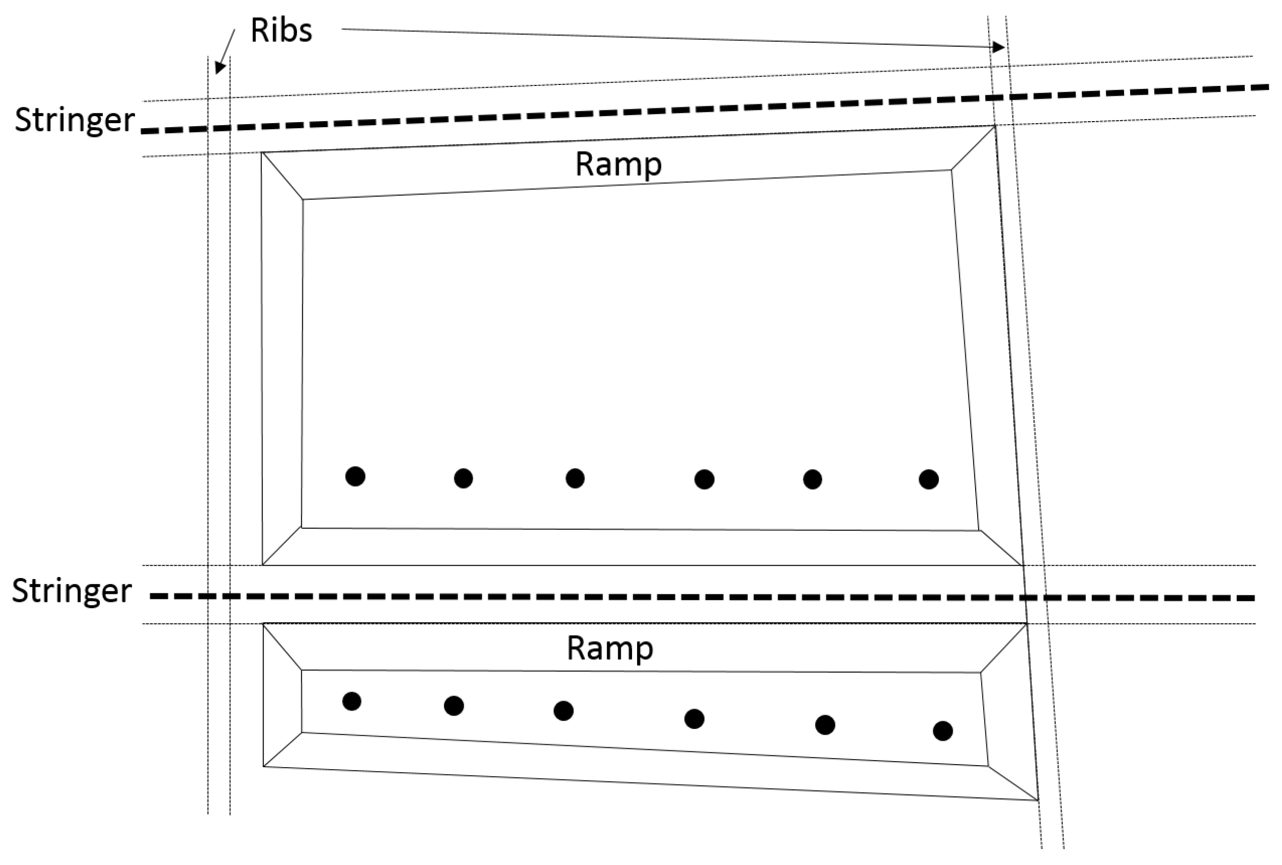
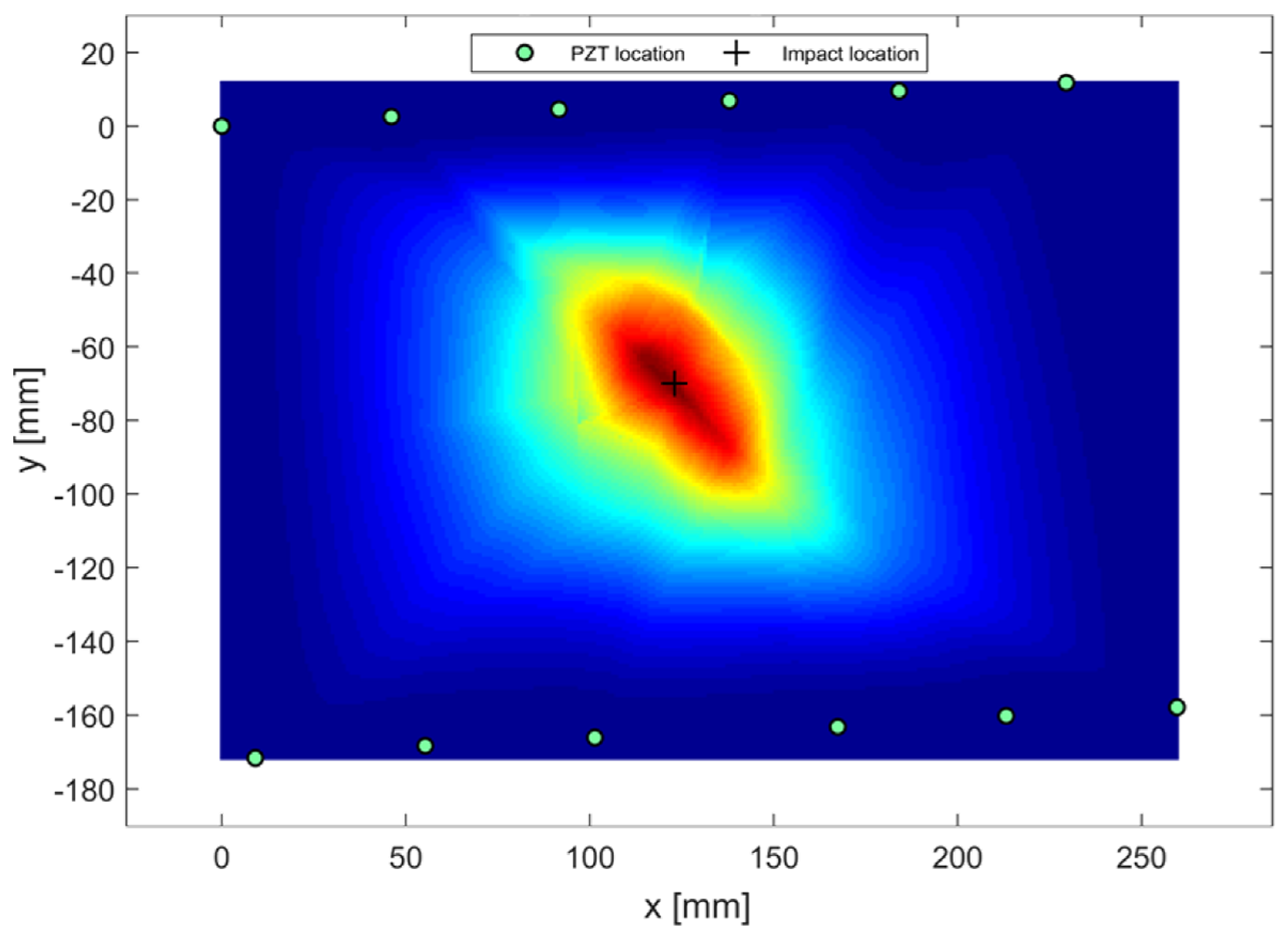
3.4. Disbonding Detection in Complex Structures

A distributed cluster of sensors used to detect propagating wave through pitch–catch approach consists of a sensor configuration as closed pattern or sensor matrix, where the sensors constitute a polygonal geometry. While monitoring a possible disbonding between stringer and thin walled composite structure, the wave propagating directly along transducers path is recorded for all possible pairs located on the opposite sides of the stiffener (see Figure 2). Stringer, structure and their interface are indeed expected to affect the paths crossing the damage. With meshless approach, the SHM mesh is constructed restoring DI datasets on the intersections defined after decisional step. The results are further interpolated to transfer health information to the structural mesh according to required resolution. A damage index approach can be efficiently employed even in this case because the wave propagating over the stringer behaves in completely different manner when the stringer is disconnected rather than bonded to the hosting structure [48]. In the latter, the wave mostly penetrates into the stringer and then is scattered back to the source location. A small amount of the energy is transmitted through the stiffener and reaches the sensors on the other side. When the stringer is completely detached, the wave travels in the thin walled structures without interacting with the stiffener. When a low velocity impact occurs below the stringer feet, usually the load partially disconnects the parts jointed together. While interrogating the structure, a portion of the energy is transmitted behind the stringer due to the wave propagating in the plate and the remaining part of the energy is reflected due to the wave penetrating into the stringer. Hence, the configuration in Figure 2 allows detecting and locating the damage using the decision-making step to select the paths affected by the hidden flaw and the dedicated algorithm to localize the damage from DI datasets, namely exploiting the paradigms of the M P 2 approaches. Namely, the approach proposed in the previous section for delamination-like damage identification in flat plates is merely extended to stiffened panels for disbonding detection. To demonstrate the feasibility of this global approach for further detecting the disbonding, another section of the same structure (Area C) is instrumented as sketched in Figure 18.
The thin walled structure is thick 6 mm and shows a ramp connecting flat parts to the stringer leg where the hosting structures is thick 8 mm as the leg and the web. The same interrogation procedure is adopted before and after a low velocity impact calibrated to lead to a disbonding. The M P 2 diagnosis is reported in Figure 19, showing the disbonding diagnosis of the meshless approach. The reconstruction is based on the multi-parameter approach where the first antisymmetric mode ( A 0 ) of propagating Lamb waves is mostly excited. The impact location is depicted as well, showing the very marginal error obtained. The map shows increasing risk where the structure is disbonded, achieving both its detection and localization. The M P 2 approach returns a negligible impact localization error when compared with the real disbonding extent. It is indeed about 35 mm, as assessed with classic ultrasonic NDT.
Another stiffened plate (Area D) is monitored as depicted in Figure 20 by using a non-regular cluster of sensors. In this case, the thin walled structure hosting the stringer has a constant thickness (8 mm). The stiffened area is characterized by the stringer legs directly connected to the surface without any ramp link. Otherwise, one of the depicted bays shows an hole very close to the stringer which prevents the design of a regular cluster of PZTs and strongly complicates the wave propagation. The damage is here simulated with loading the lower leg of the stringer to localize the damage only lower side of the stringer. No matter what the geometry and complexities are, the M P 2 approach is able to correctly detect and locate the stringer disbonding. The result depicted in Figure 21 shows the reasonable result obtained in terms of localization even when a very complex geometry is considered. Furthermore, the diagnosis correctly suggests the leg which is currently damaged.

4. Discussion and Concluding Remarks

The work deals with efficient identification and localization of damage in complex composite structures by allowing a multi-path and multi-parameter approach. Despite the different and less regular geometries involved compared to flat composite plates, the tomographic method based on unsupervised threshold definition and multi-parameter processing does not show any indecision in detecting and locating the impact damages. Good results are obtained even while reconstructing damaged area where thickness ramps are present as well as where holes and stiffeners are located near the monitored area. The results reported show the effectiveness of the implemented approach combining mesh-less reconstruction from statistical selection of propagation paths with multi-parameter analysis and data fusion techniques to provide higher levels of probability of detection for all the investigated damage scenarios. Furthermore, the result is often even more promising than that of conventional mesh-based approaches with fewer computational costs possible. It is worth noting that the methodology proposed is here applied to aeronautical structures, where the SHM has been demonstrated to improve the performances and the operations. However, it can be applied to monitor all types of structures, including isotropic and anisotropic components. The M P 2 framework presented in this work is indeed general while the features affected by the hidden flaw can be addressed to the appropriate event-induced damage (i.e., impact rather than fatigue-induced damage or others). In addition, although impacts may randomly occur, it is worth noting that the position is a priori established to make more challenging the investigation and the central location is likely chosen because: (i) that area is characterized by less dense mesh; and (ii) the closer the damage is to the sensors, the more accurate is the reconstruction [49].
One of the more challenging aspects is the robustness of the methodology versus number of sensors adopted, which may also varying during the system lifetime. Sensors may fail due to the harsh condition that they have to withstand [50,51] and a self diagnosis approach should be integrated together with a health management strategy continuously pursuing the minimum target to achieve the prescribed POD. This means that the effect of missing sensors has to be addressed a priori to continuously predict the minimum detectable damage. On the other hand, the impact of SHM systems strongly depends upon the weight introduced into the monitored vehicle. Although PZT sensors are much lighter than classic probes, they need connections, wiring and driving hardware to be mounted on the aircraft. This means that a reliability oriented approach is needed to have the minimum detectable damage very close to the system target to minimize the weight by using as few as sensors possible.

Author Contributions

V.M. conceived the proposed multi-parameter methodology, wrote the paper, carried out numerical simulations and measurements and post-processed the whole datasets for diagnosis purpose. N.D.B. designed the experiments and was deeply involved during the measurements campaign on the lower wing panel. L.M. reviewed the article. E.M. and F.R. supervised the activity.

Funding

The research leading to these results has received funding from the European Union’s Seventh Framework Programme for research, technological development and demonstration under grant agreement no 284562 (SARISTU Project).

Conflicts of Interest

The authors declare no conflict of interest.

Abbreviations

The following abbreviations are wisely used in this manuscript:
SHMStructural Health Monitoring
NDTNon destructive Testing
GWGuided Wave
PZTLead zirconate titanate (piezoelectric material)
PODProbability of detection
PFAProbability of false alarm

References

  1. Jones, R. Mechanics Of Composite Materials; Materials scIence And Engineering Series; Taylor & Francis: Abingdon, UK, 1998. [Google Scholar]
  2. Megson, T. Aircraft Structures for Engineering Students, 5th ed.; Butterworth-Heinemann: Boston, MA, USA, 2013. [Google Scholar]
  3. Maio, L.; Monaco, E.; Ricci, F.; Lecce, L. Simulation of low velocity impact on composite laminates with progressive failure analysis. Compos. Struct. 2013, 103, 75–85. [Google Scholar] [CrossRef]
  4. USA Department of Defense. MIL-HDBK 17-3F: Composite Materials Handbook; Department of Defense Handbook: Washington, DC, USA, 2002.
  5. USA Department of Defense. JSSG-2006, Aircraft Structures; Department of Defense Joint Service Specification Guide: Washington, DC, USA, 1998.
  6. US Department of Transportation—Federal Aviation Administration. AC No: 20-107B. Composite Aircraft Structure; US Department of Transportation—Federal Aviation Administration: Washington, DC, USA, 2009.
  7. Cot, L.; Wang, Y.; Bes, C.; Gogu, C. Scheduled and SHM structural airframe maintenance applications using a new probabilistic model. In Proceedings of the 7th European Workshop on Structural Health Monitoring, EWSHM 2014—2nd European Conference of the Prognostics and Health Management (PHM) Society, Nantes, France, 8–11 July 2014; pp. 2306–2313. [Google Scholar]
  8. Clean Sky 1 GRA—Green Regional Aircraft. Available online: http://www.cleansky.eu/green-regional-aircraft-gra (accessed on 16 September 2018).
  9. Wolcken, P.C.; Papadopoulos, M. SARISTU—Smart Intelligent Aircraft Structures; Springer: Berlin, Germany, 2015. [Google Scholar]
  10. Clean Sky 2 RA—Regional Aircraft. Available online: http://www.cleansky.eu/regional-aircraft (accessed on 16 September 2018).
  11. Giurgiutiu, V. Structural Health Monitoring with Piezoelectric Wafer Active Sensors, 2nd ed.; Academic Press: Oxford, UK, 2014. [Google Scholar]
  12. Viktorov, I. Rayleigh and Lamb Waves: Physical Theory and Applications; Ultrasonic Technology; Springer: New York, NY, USA, 1967. [Google Scholar]
  13. Maio, L.; Memmolo, V.; Ricci, F.; Boffa, N.; Monaco, E. Investigation on fundamental modes of guided waves propagating in symmetric and nonsymmetric composite laminates. Proc. Inst. Mech. Eng. Part C J. Mech. Eng. Sci. 2017, 231, 2988–3000. [Google Scholar] [CrossRef]
  14. Abrate, S. Impact on Composite Structures; Cambridge University Press: Cambridge, UK, 1998. [Google Scholar] [CrossRef]
  15. Memmolo, V.; Pasquino, N.; Ricci, F. Experimental characterization of a damage detection and localization system for composite structures. Measurement 2018, 129, 381–388. [Google Scholar] [CrossRef]
  16. Hay, T.R.; Royer, R.L.; Gao, H.; Zhao, X.; Rose, J.L. A comparison of embedded sensor Lamb wave ultrasonic tomography approaches for material loss detection. Smart Mater. Struct. 2006, 15, 946. [Google Scholar] [CrossRef]
  17. Testoni, N.; De Marchi, L.; Marzani, A. Detection and characterization of delaminations in composite plates via air-coupled probes and warped-domain filtering. Compos. Struct. 2016, 153, 773–781. [Google Scholar] [CrossRef]
  18. Zhao, X.; Royer, R.L.; Owens, S.E.; Rose, J.L. Ultrasonic Lamb wave tomography in structural health monitoring. Smart Mater. Struct. 2011, 20, 105002. [Google Scholar] [CrossRef]
  19. De Marchi, L.; Marzani, A.; Moll, J.; Kudela, P.; Radzieński, M.; Ostachowicz, W. A pulse coding and decoding strategy to perform Lamb wave inspections using simultaneously multiple actuators. Mech. Syst. Signal Process. 2017, 91, 111–121. [Google Scholar] [CrossRef]
  20. Michaels, J.E.; Michaels, T.E. Guided wave signal processing and image fusion for in situ damage localization in plates. Wave Mot. 2007, 44, 482–492. [Google Scholar] [CrossRef]
  21. Croxford, A.J.; Moll, J.; Wilcox, P.D.; Michaels, J.E. Efficient temperature compensation strategies for guided wave structural health monitoring. Ultrasonics 2010, 50, 517–528. [Google Scholar] [CrossRef] [PubMed]
  22. US Department of Defence. MIL-HDBK No: 1823A. Non Destructive Evaluation System Reliability Assessment; US Department of Defence: Washington, DC, USA, 2009.
  23. Janapati, V.; Kopsaftopoulos, F.; Li, F.; Lee, S.; Chang, F.K. Damage detection sensitivity characterization of acousto-ultrasound-based structural health monitoring techniques. Struct. Health Monit. 2016, 15, 143–161. [Google Scholar] [CrossRef]
  24. Worden, K.; Allen, D.W.; Sohn, H.; Farrar, C.R. Damage detection in mechanical structures using extreme value statistics. In Smart Structures and Materials 2002: Modeling, Signal Processing, and Control; International Society for Optics and Photonics: Bellingham, WA, USA, 2002; Volume 4693, pp. 289–299. [Google Scholar]
  25. Monaco, E.; Memmolo, V.; Ricci, F.; Boffa, N.; Maio, L. Guided waves based SHM systems for composites structural elements: Statistical analyses finalized at probability of detection definition and assessment. In Proceedings of the SPIE—The International Society for Optical Engineering, San Diego, CA, USA, 8–12 March 2015; Volume 9438. [Google Scholar] [CrossRef]
  26. Sohn, H.; Farrar, C.; Hunter, N.; Worden, K. Structural health monitoring using statistical pattern recognition techniques. J. Dyn. Syst. Meas. Control 2001, 133, 706–711. [Google Scholar] [CrossRef]
  27. Cottone, G.; Gollwitzer, S.; Heckenberger, U.; Straub, D. Reliability-oriented optimization of replacement strategies for monitored composite panels for aircraft structures. In Proceedings of the 9th International Workshop on Structural Health Monitoring: A Roadmap to Intelligent, Stanford, CA, USA, 10–13 September 2013; Volume 2, pp. 2728–2735. [Google Scholar]
  28. Gianneo, A.; Carboni, M.; Giglio, M. Feasibility study of a multi-parameter probability of detection formulation for a Lamb waves based structural health monitoring approach to light alloy aeronautical plates. Struct. Health Monit. 2017, 16, 225–249. [Google Scholar] [CrossRef]
  29. Maio, L.; Ricci, F.; Memmolo, V.; Monaco, E.; Boffa, N. Application of laser Doppler vibrometry for ultrasonic velocity assessment in a composite panel with defect. Compos. Struct. 2018, 184, 1030–1039. [Google Scholar] [CrossRef]
  30. Maio, L.; Memmolo, V.; Ricci, F.; Boffa, N.; Monaco, E.; Pecora, R. Ultrasonic wave propagation in composite laminates by numerical simulation. Compos. Struct. 2016, 121. [Google Scholar] [CrossRef]
  31. Staszewski, W.; Boller, C.; Tomlinson, G. Health Monitoring of Aerospace Structures: Smart Sensor Technologies and Signal Processing; John Wiley & Sons: Hoboken, NJ, USA, 2004. [Google Scholar]
  32. Memmolo, V.; Ricci, F.; Maio, L.; Boffa, N.; Monaco, E. Model assisted probability of detection for a guided waves based SHM technique. In Proceedings of the SPIE—The International Society for Optical Engineering, Las Vegas, NV, USA, 20–24 March 2016; Volume 9805. [Google Scholar] [CrossRef]
  33. Cremer, L.; Heckl, M.; Petersson, B.A.T. Structure-Borne Sound: Structural Vibrations and Sound Radiation at Audio Frequencies; Springer: Berlin, Germany, 2005. [Google Scholar]
  34. Harris, F.J. On the use of windows for harmonic analysis with the discrete Fourier transform. Proc. IEEE 1978, 66, 51–83. [Google Scholar] [CrossRef] [Green Version]
  35. Auld, B. Acoustic Fields and Waves in Solids; Ripol Classic: Moscow, Russia, 1975. [Google Scholar]
  36. Oppenheim, A.; Verghese, G. Signals, Systems and Inference, Global Edition; Pearson Education: London, UK, 2016. [Google Scholar]
  37. Memmolo, V.; Maio, L.; Boffa, N.D.; Monaco, E.; Ricci, F. Damage detection tomography based on guided waves in composite structures using a distributed sensor network. Opt. Eng. 2015, 55, 011007. [Google Scholar] [CrossRef]
  38. Memmolo, V.; Boffa, N.; Maio, L.; Monaco, E.; Ricci, F.; Pasquino, N. Experimental characterization of a composite structures health monitoring methodology. In Proceedings of the 3rd IEEE International Workshop on Metrology for Aerospace, MetroAeroSpace, Florence, Italy, 22–23 June 2016. [Google Scholar] [CrossRef]
  39. Worden, K.; Manson, G.; Fieller, N. Damage detection using oulier analysis. J. Sound Vib. 2000, 229, 647–667. [Google Scholar] [CrossRef]
  40. Fugate, M.; Sohn, H.; Farrar, C. Vibration-based damage detection using statistical process control. Mech. Syst. Signal Process. 2001, 15, 707–721. [Google Scholar] [CrossRef]
  41. Sohn, H.; Czarnecki, J.A.; Farrar, C.R. Structural health monitoring using statistical process control. J. Struct. Eng. 2000, 126, 1356–1363. [Google Scholar] [CrossRef]
  42. Bornn, L.; Farrar, C.R.; Park, G.; Farinholt, K. Structural health monitoring with autoregressive support vector machines. J. Vib. Acoust. 2009, 131, 021004. [Google Scholar] [CrossRef]
  43. Farrar, C.; Worden, K. Structural Health Monitoring: A Machine Learning Perspective; John Wiley & Sons: Hoboken, NJ, USA, 2012. [Google Scholar]
  44. Laboratory, L.A.N.; States, U. A Comparison Study of Modal Parameter Confidence Intervals Computed Using the Monte Carlo and Bootstrap Techniques; Department of Energy, Office of the Assistant Secretary, Management and Administration: Washington, DC, USA, 1998.
  45. Hazewinkel, M. Encyclopaedia of Mathematics: Volume 3 Heaps and Semi-Heaps—Moments, Method of (in Probability Theory); Encyclopaedia of Mathematics; Springer: New York, NY, USA, 2013. [Google Scholar]
  46. Mitra, M.; Gopalakrishnan, S. Guided wave based structural health monitoring: A review. Smart Mater. Struct. 2016, 25, 053001. [Google Scholar] [CrossRef]
  47. Moll, J.; Schulte, R.; Hartmann, B.; Fritzen, C.P.; Nelles, O. Multi-site damage localization in anisotropic plate-like structures using an active guided wave structural health monitoring system. Smart Mater. Struct. 2010, 19. [Google Scholar] [CrossRef]
  48. Ricci, F.; Monaco, E.; Maio, L.; Boffa, N.; Mal, A. Guided waves in a stiffened composite laminate with a delamination. Struct. Health Monit. 2016, 15, 351–358. [Google Scholar] [CrossRef]
  49. Memmolo, V.; Ricci, F.; Boffa, N.; Maio, L.; Monaco, E. Structural health monitoring in composites based on probabilistic reconstruction techniques. Procedia Eng. 2016, 167, 48–55. [Google Scholar] [CrossRef]
  50. Memmolo, V.; Park, Y.; Lilov, M.; Monaco, E.; Ricci, F. Preliminary acousto-ultrasonic investigation for multi-parameter transducer self-diagnostic system in composites. Compos. Struct. 2018, 202, 1229–1238. [Google Scholar] [CrossRef]
  51. Mueller, I.; Fritzen, C.P. Inspection of piezoceramic transducers used for structural health monitoring. Materials 2017, 10, 71. [Google Scholar] [CrossRef] [PubMed]
Figure 1. Lamb waves response sensed using pitch–catch approach as a synthesis of wave propagation.
Aerospace 05 00111 g001
Figure 2. Transmitter-receiver paths for double-line array configuration around stringer in a stiffened structure.
Aerospace 05 00111 g002
Figure 3. Kolmogorov–Smirnov testing: Comparison between analytical and experimental cumulative distribution functions of the signal response noise in a composite panel without defect [37].
Aerospace 05 00111 g003
Figure 4. According to Betti reciprocal theorem applied to direct wavefield, the same relative influence is found considering A-B and B-A pairs.
Aerospace 05 00111 g004
Figure 5. Circular sensors cluster with all interrogating paths (a). Representation of a typical bi-parametric structural mesh (b). Selected paths (light grey lines) and their intersections (sparse black points) are highlighted in the background.
Aerospace 05 00111 g005
Figure 6. Scheme followed during experiment.
Aerospace 05 00111 g006
Figure 7. Tomographic analysis of the numerical test-case: reconstruction of damage based on energy level (a); and reconstruction of damage based on weighted energy level (b).
Aerospace 05 00111 g007
Figure 8. Tomographic analysis of the numerical test-case: map of damage based on single ToF (a); and multi-parameter (b) approach.
Aerospace 05 00111 g008
Figure 9. Cluster of sensor with all passible propagation paths (a); and typical mesh for mesh-based reconstruction approach (b).
Aerospace 05 00111 g009
Figure 10. Tomographic analysis of the numerical test-case: mesh based multi-parameter approach (a); and M P 2 meshless image reconstruction (b).
Aerospace 05 00111 g010
Figure 11. Lower wing panel mounted on the outer wing box of a commercial aircraft. Structural and impacts details used for the design of the SHM configuration. Red crosses represent impact locations while capitalized letters label the monitored area whose SHM analysis is reported afterwards.
Aerospace 05 00111 g011
Figure 12. Dispersion (a); and tuning (b) characteristics of the A 0 Lamb wave mode travelling through the 6 mm composite media.
Aerospace 05 00111 g012
Figure 13. Sensor clusters adopted to monitor delamination-like damages in flat thin walled composite (Area A in Figure 11).
Aerospace 05 00111 g013
Figure 14. Typical time history of the propagating wave captured at sensor location. Several modes and reflections propagating at frequency of 60 KHz.
Aerospace 05 00111 g014
Figure 15. M P 2 damage detection of flat thin walled composite sketched in Figure 13 (Area A).
Aerospace 05 00111 g015
Figure 16. Sensor clusters adopted to monitor delamination-like damages in tapered thin walled composite (Area B in Figure 11).
Aerospace 05 00111 g016
Figure 17. M P 2 damage detection of tapered thin walled composite sketched in Figure 16 (Area B).
Aerospace 05 00111 g017
Figure 18. Sensor clusters adopted to monitor disbondings in stiffened thin walled composite (Area C in Figure 11).
Aerospace 05 00111 g018
Figure 19. M P 2 diagnosis of the stringer disbonding occurred below the stringer web depicted in Figure 18 (Area C).
Aerospace 05 00111 g019
Figure 20. Sensor clusters adopted to monitor disbondings in stiffened thin walled composite ( Area D in Figure 11).
Aerospace 05 00111 g020
Figure 21. M P 2 diagnosis of the stringer disbonding occurred below a stringer leg depicted in Figure 20 (Area D).
Aerospace 05 00111 g021
Table 1. Elastic properties of graphite-epoxy laminae adopted for the 6 mm-thick composite plate.
PropertiesBiaxialUniaxial5Harness
ρ [kg/m 3 ]179017901770
E 1 [MPa]81,000152,000158,420
E 2 [MPa]81,00088008800
E 3 [MPa]880088008800
G 12 = G 13 = G 23 [MPa]410041003600
ν 12 = ν 13 = ν 23 0.310.310.31

