Abstract
The paper introduces and describes the recent and still ongoing development activities performed in Luxembourg for In-Orbit Attach Mechanisms for (Drag) Sails Modules to be operated from Space Tugs. After some preparatory work aiming at understanding the possible operational aspects and implications of mating interfaces between these space systems, three possible designs of In-Orbit Attach Mechanisms have been proposed and completed for their 3D (Metal and Plastic) Printing, a new manufacturing technology assessed within this project. The Plastic-printed prototype underwent a series of automated tests in which a robotic arm, equipped with an advanced force sensor, replicated four docking scenarii in ideal and degraded modes. The observation of the forces and torque behaviors at and after impact allowed one to characterize the typical patterns for the various contacts but also, to identify a type of potentially dramatic impact for the safety of the docking and its equipment: in the case of the off-axis approach, “point” contacts shall be avoided, as they instantaneously transfer the total kinetic energy in a small area that could break.
1. Introduction
In the future, some key Space applications like (Active) Debris Removal and Space Resources (Mining) could benefit from the combined use of Spaceborne Sails and/with “Space Tugs”, with the latter being in-orbit infrastructures offering stored resources and/or available services for other missions. Rendez-vous between satellites and On-Orbit Servicing (OOS) will thus become classical operations requiring multiple and repeated docking or berthing connections with or without transfers of materials.
The work presented in this paper relates to recent and ongoing activities in Luxembourg aiming at preparing the Team for these future challenges: Spaceborne Sail (Modules) are being developed, and In-Orbit Attach Mechanisms are being investigated, prototyped, and tested (this in the context of Spaceborne Sails stored onto and operated from Space Tugs as OOS Adds-on for de-orbiting, inter-planetary propulsion, and/or transport of goods).
For comprehension, the Spaceborne Sails and Space Tugs systems have now been introduced.
1.1. Spaceborne Sails
Since their inception back in 1921 by Constantin Tsiolkovski, spaceborne sails have been conceived of as large, deployable, lightweight, flat, and highly reflective membranes supporting photonic propulsion. The main historical projects of such “solar” sails were (a) the NASA developments for a rendezvous with the Halley’s Comet in the 70s and (b) the international efforts for the Marco Polo race to the Moon supposed to start in 1992 [1]. Eventually, the first successful deployment and operation of a Solar Sail (SRS) in Space happened in 2010 with the Japanese IKAROS project [2].
It is interesting to recall here that photonic propulsion (thanks to solar sails) has been identified as one of the most powerful, elegant, and versatile ways of travelling in Space. Solar sails can indeed navigate towards or outwards from the Sun and/or keep a stationary position in Space. In particular, for this research/paper on Spaceborne Sails combined with Space Tugs, the concept of solar-sail-based Stopover Cyclers for cargo transportation missions needs to be highlighted, along with Figure 1 [3]:

Figure 1.
The generic Stopover Cycler between a Starting planet and a Target planet and its four phases: “in the first one, referred to as S-T phase, the spacecraft is transferred from the starting to the target planet. The spacecraft then orbits around the target and waits for the next opportunity to return back. This waiting time at the target is denoted by T-T phase, whereas the return voyage towards the starting planet is called T-S phase. The stopover cycler ends with a waiting S-S phase at the starting planet, whose duration is equal to the time length necessary for the planets to return in the same relative configuration they occupied at time t0” [3].
If spaceborne sails originated thus from missions requiring photonic propulsion, they have (recently) evolved towards other applications:
- As Drag Sails (DRS), in which the deployed area is exposed to atmospheric fluxes to bring in shorter-time (satellite) debris down toward Earth and their relative destruction during re-entry.
- As “Functional” Sails, proposed for use either as a large solar power generator or as antenna, or other applications requiring the implementation of additional (flexible) functionalities on the deployed sail membrane.
Although several configurations exist, spaceborne sails have often been conceived of as square flat systems made of four sail segments deployed by booms from a box-shaped “Sail Module”, shown open on Figure 2a. Two important parameters of (square) sails are the sidelength “S” and the “Sail Assembly Loading”, which is defined as the ratio of the complete sail module mass (i.e., for sail film + all sail elements, booms, structures, and mechanisms) to the deployed sail area.
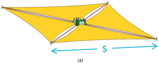
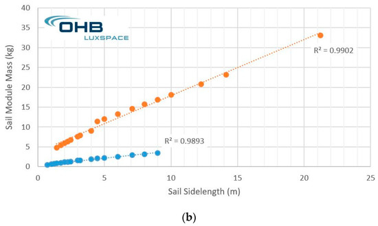
Figure 2.
Typical configuration of square sail (module) deployed and tensed by four booms: (a) drawing of typical sail module showing at the center the booms mechanisms and the sail containers from which the sail segments are deployed, forming ultimately a flat square of sidelength “S”; (b) current and near-term sail module masses for two booms technologies behave almost linearly with respect to sail sidelength “S” [4].
The linear behavior shown on Figure 2b of the Sail Module mass with the Sail Sidelength is given by the following best fit equations, depending on the chosen boom technology:
“Large, Heavy” Sail Module mass [kg] = 1.42 × (Sail Sidelength [m]) + 3.72
“Small, Light” Sail Module mass [kg] = 0.35 × (Sail Sidelength [m]) + 0.39
Equation (1) can be used indicatively for Sail Sidelengths over [1.4; 21.2] meters, while Equation (2) can be used indicatively for Sail Sidelengths over [0.7; 9.0] meters. These equations allow thus to estimate the Sail Assembly Loading of current sail modules. Table 1 here below indicate current and future expectations in terms of this key technical parameter, as enabler for sail-based missions:

Table 1.
Current and future expectations for Sail Assembly Loadings [4,5,6]. Data is given in g·m−2.
1.2. “Space Tugs”
The name “Space Tug” originates back from 1949/1953 [7]. Under this generic concept, a reference is (still) made to modular infrastructures established/assembled in “parking” orbits and offering resources for On-Orbit Servicing (OOS) to other missions and/or satellites [8].
NASA investigated the Space Tug concept thoroughly in the 70s [9]. At that time, it was intended to be a reusable multipurpose space vehicle designed to transport payloads to different orbital inclinations. Utilizing mission-specific combinations of its three primary modules (crew, propulsion, and cargo) and a variety of supplementary kits, the Space Tug would have been capable of numerous space applications:
As seen on the next Figure 3a, the typical (modular) resources stored and transferred to/from Space Tugs were, and are again, proposed to be [8,9]:
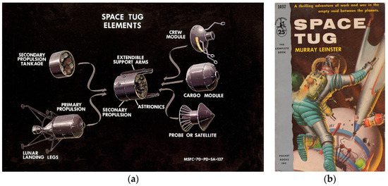
Figure 3.
Two historical documents on “Space Tugs”: (a) a NASA drawing showing the various modules considered; (b) coverpage of one of the first documents (1953) citing and defining the “Space Tug” concept [7].
- Crew Modules;
- Cargo Modules;
- (Stored) Probe or Satellite;
- Primary and Secondary Propulsion Modules (e.g., for orbit control and/or repositioning);
- Propellant and/or Pressurant (for refuelling);
- Robotic Elements (e.g., for assembly, for berthing, for logistic);
- Landing Legs;
- Systems for (Active) Debris Removal.
In the present research project, it is proposed to consider the implementation of Spaceborne Sail Modules on Space Tugs to support missions like:
- De-orbiting and re-entry with “Drag Sails”;
- Inter-planetary journeys (based on photonic propulsion) with “Solar Sails”;
- Space resources (mining) and the relative transport of fluidic and/or solid material with “Solar Trailers”, possibly with Stopover Cyclers to/from the Main Asteroid Belt.
These different Sail Module applications with Space Tugs will in any case require rendez-vous and docking/berthing operations and hence specific interfaces, and to start: In-Orbit Attach Mechanism(s).
2. Materials and Methods
2.1. “Actors” Involved in (Drag) Sails Modules Operations with/from Space Tugs
The focus of the research is In-Orbit Attach Mechanisms for (Drag) Sails Modules to be operated from Space Tugs; the project was started by identifying the possible “Actors” involved, their operations, and their interfaces. These are depicted in the following Figure 4:
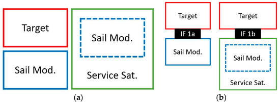
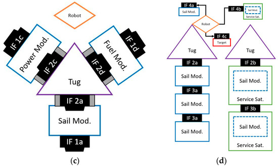
Figure 4.
Main actors and interfaces involved in (Drag) Sail Modules operated from Space Tugs: (a) Target satellite, (Drag) Sail Module and Service satellite embedding or not a (Drag) Sail Module; (b) possible interfaces/attachments providing a (Drag) Sail Module to the Target satellite; (c) the Space Tug and some of its offered modules awaiting OOS usage. The Space Tug can be conceived of with or without a robot (e.g., arm); (d) a Space Tug with robotic arm offering Sail Modules (left); a Space Tug offering Sail Modules through Service Satellites, each equipped with a Sail Module (right).
- The Target satellite is the satellite requiring the in-orbit attachment of a (Drag) Sail Module (for its de-orbiting/re-entry). The Target satellite could be cooperative or not.
- The (Drag) Sail Module is an add-on, which was initially stored onto the Space Tug and was planned to be attached to a Target satellite. This module is not equipped with any Attitude and Orbit Control Subsystem (AOCS) allowing autonomous docking with the Target satellite.
- The Service satellite offers OOS by bringing/attaching the (Drag) Sail Module to the Target satellite. The Service satellite like the (Drag) Sail Module is initially stored onto the Space Tug. It is capable of autonomously leaving the Space Tug, approaching the Target satellite, performing the rendez-vous connections, and deploying its (Drag) Sail if available. The Target satellite could also be equipped, or not, with robotic facilities.
- The Space Tug carries all service modules. It has AOCS capabilities to control/correct its orbit, and it can be equipped or not with robotic facilities.
- The Robot is planned for berthing and/or in-orbit assembly. It can be “fixed” if installed onto and operated from the Space Tug, or “mobile” if installed onto and operated from the Service satellite.
2.2. In-Orbit Attach Mechanisms for (Drag) Sails Modules
Having understood the main operations and interfaces between involved actors, the project initiated the design of In-Orbit Attach Mechanisms for (Drag) Sail Modules. After a survey of the main docking/berthing systems ever produced for Space applications (e.g., Apollo DS [10], SSVP [11], APAS/APAS-95 [12,13], IDSS [14], MCDS [15], UDP [16], ASSIST [17], OECS [18], and ASDS [19]), three mechanisms consisting of two identical androgyne (for ease of printability) parts were derived for this project:
- The 1st Mechanism shown hereafter in Figure 5a is based on the International Docking System Standard (IDSS) [14]. The prototype of the androgyne part features an envelope of 110 mm × 60.5 (height) mm. When 3D Metal (Aluminum) printed, each prototype will weigh about 254 grams.
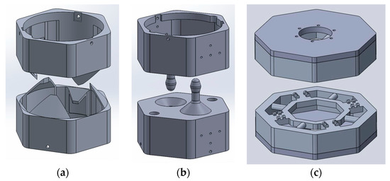 Figure 5. The three In-Orbit Attach Mechanisms designed for the project (a) based on the International Docking System Standard (IDSS) [14]; (b) based on the Universal Docking Port (UDP) [16]; and (c) based on the concept proposed for the ESA Mars Sample Return (MSR) mission [20].
 - The 2nd Mechanism shown hereafter in Figure 5b is based on the Universal Docking Port (UDP) [16]. The prototype of the androgyne part features an envelope of 110 mm × 110 (height) mm. When 3D Metal (Aluminum) printed, each prototype will weigh about 371 grams.
- The 3rd Mechanism shown hereafter in Figure 5c is based on the concept proposed for the ESA Mars Sample Return (MSR) mission [20]. The prototype of the androgyne part features an envelope of 200 (dia.) mm × 50 (height) mm. When 3D (Plastic, here PLA) printed and assembled, each prototype will weigh about 329 grams.
2.3. Test Cases for the Automated Test at FANUC Luxembourg
As part of the In-Orbit Attach Mechanisms development, a verification plan has been prepared including a first automated (i.e., robotized) test of the connection/matching between the two parts of the 3rd (Plastic-printed) Mechanism. The verification plan intends to replicate the same automated test on the other two (metal-printed) mechanisms as soon as they are produced and made available for such test.
Considering a fixed “Passive” part and the other mobile “Active” part approaching at 3 cm/s similarly to the Soyuz when close (<10 m) to the International Space Station (ISS) [21], four test cases have been identified (see Figure 6):
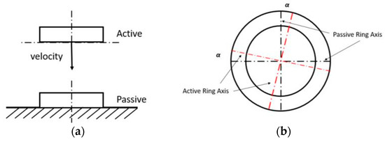
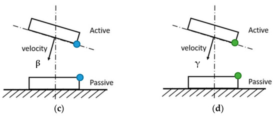
Figure 6.
The four test cases: (a) Nominal case: ideal approach along vertical “Z” axis; (b) Non-nominal case 1: misalignment in the contact plane; (c) Non-nominal case 2: misalignment out of the contact plane (edge contact); (d) Non-nominal case 3: misalignment out of the contact plane (vertex contact).
- Nominal case: ideal approach along the docking (i.e., “Z”) axis;
- Non-nominal case 1: misalignment of an angle α in the plane perpendicular to the docking axis;
- Non-nominal case 2: misalignment of an angle β out of the plane perpendicular to the docking axis. The first impact occurs here via two parallel edges of the (active and passive) polygonal parts;
- Non-nominal case 3: misalignment of a conic angle γ out of the plane of the docking axis. The first impact occurs here via two vertices of the (active and passive) polygonal parts.
For the Non-nominal cases (1, 2, and 3) investigating angular misalignments, the values of the misalignments (respectively α, β, and γ) have been identified with two criteria: (1) as angular limit enabling the geometrical matching between parts, and (2) as angular limit imposed by the test facility.
2.4. Facility Used for the Automated Test at FANUC Luxembourg
The facility kindly made available by FANUC Luxembourg for the automated test on the 3rd Mechanism was a slightly upgraded version of the FANUC Educational Package [22]. This compact “all-in-one” robotic facility, shown here after in Figure 7a, has been specifically designed for educational, hands-on training in schools and universities. Upgraded with FANUC’s auto-calibrating Force Sensor, the robotic facility used for the tests consisted in:
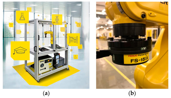
Figure 7.
Robotic facility used for the automated test at FANUC Luxembourg, located in Echternach: (a) the FANUC Educational Package equipped with the 6-Axis Mechanical Robot LR-Mate 200iD/4S and (b) the auto-calibrating Force Sensor FS-15iA mounted on the robot of the facility.
- FANUC’s 6-Axis Mechanical Robot LR-Mate 200iD/4S (with max payload of 4 kg and reach of 550 mm) as part of the standard Educational Package;
- FANUC’s auto-calibrating Force Sensor FS-15iA, as upgrade for these tests;
- FANUC’s ROBOGUIDE Simulation Software.
The FANUC’s auto-calibrating force sensor FS-15iA has different features to achieve better performances. To test the 3rd Mechanism, three of them have been used, according to the test case:
- The Constant Push feature enables the robot to push with constant force in the Z direction. This feature has been used for the Nominal case.
- The Phase Search feature performs the phase search before the engagement, aligning the mechanism by rotating the active part. This feature has been used for the Non-nominal case 1 (roll misalignment).
- The Face Match feature provides the robot with the ability of align and match the faces of the two parts. This feature has been used for the Non-nominal cases 2 and 3 (yaw/pitch misalignment).
The few pictures shown on Figure 8 depict the final and complete test configuration used for all test cases:
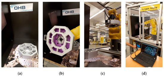
Figure 8.
Final and complete test configuration used for the Automated Test on the 3rd Mechanism: (a) passive part of the prototype fixed on the test bench; (b) active part of the prototype (equipped with a “star tracker/docking” camera, visible on the left side) mounted on the robot via the force sensor; (c) a view of the principal elements of the test before sequence start (d) a view of the principal elements of the test during sequence—note on the laptop: the image taken simultaneously by the mounted “star tracker/docking” camera.
3. Results
The following sections present the impact forces and torques resulting from the automated tests (all conducted with constant approach velocity of 3 cm/s, starting from the same height above the interface plane) for the four test cases. Where noticeable, some interpretations, as well as the experimental conclusions that can be drawn, are given.
3.1. Nominal Case
The Nominal case deals with an ideal approach along the docking axis Z. The forces and torques experienced at impact for this case are presented in the next Figure 9:
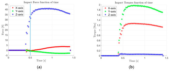
Figure 9.
Nominal Case (v = 0.030 m/s): (a) forces at impact and (b) torques at impact.
The impact (step) force along Z axis is noticeable around 0.5 s; the level is kept almost constant after contact by the “constant push” feature of the Force Sensor. The smaller forces and torques along the X and Y axis after contact have been attributed to possible misalignments, loss of fixations and geometrical features of the 3D printed parts. However, such “real” effects will need to be considered for future design activities at mechanism and at system levels (especially for what relates to relative attitude control during docking).
3.2. Non-Nominal Case 1
The Non-nominal case 1 deals with a misalignment of an angle α in the plane perpendicular to the docking axis Z. The forces and torques experienced at impact for this case are presented in the next Figure 10:
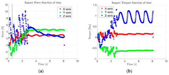
Figure 10.
Nominal Case (v = 0.030 m/s; α = 2 deg): (a) forces at impact and (b) torques at impact.
A clear and unique impact (force) along the Z axis is not noticeable around 0.5 s. Instead, oscillatory behaviors are observed and attributed to the control laws implemented by the “phase search” feature of the Force Sensor.
3.3. Non-Nominal Case 2
The Non-nominal case 2 deals with a misalignment of an angle β out of the plane perpendicular to the docking axis Z (the Active part impacts the Passive part along edges/borders). The forces and torques experienced at impact for this case are presented in the next Figure 11:
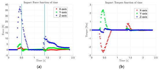
Figure 11.
Nominal Case (v = 0.030 m/s; β = 3 deg): (a) forces at impact and (b) torques at impact.
A clear and first impact (force) along Z is noticeable around 0.5 s; a second and reduced impact (force) along Z is also noticeable about 1 s later. This second impact results from the “face match” feature of the Force Sensor that rotates the Active part to ensure the final perfect contact between the parts.
3.4. Non-Nominal Case 3
The Non-nominal case 3 deals with a misalignment of a conic angle γ out of the plane of the docking axis Z (the Active part impacts the Passive part on vertices/corners). The forces and torques experienced at impact for this case are presented in the next Figure 12:
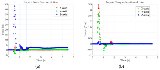
Figure 12.
Nominal Case (v = 0.030 m/s; γ = 3.6 deg): (a) forces at impact and (b) torques at impact.
A clear and first impact (force) along Z is noticeable around 0.5 s; two other reduced impacts (forces) along Z are also noticeable subsequently. These smaller impacts result again from the “face match” feature of the Force Sensor that rotates the Active part to ensure the final perfect contact between the parts. The level of the first impact is similar to the one observed in the Nominal case and Non-nominal 2 case; however, it applies here instantly to the corners (i.e., points) and not to distributed areas (like faces or edges/borders).
4. Discussion
A TRL 4 has been reached thanks to the automated test on the 3D (Plastic) printed prototype of the 3rd In-Orbit Attach Mechanism designed for (Drag) Sail Modules to be operated from Space Tugs. The lessons learned and the technical results obtained will be re-injected in subsequent design activities.
An important observation was made with the Non-nominal case 3 in which contact impact occurred at/by vertices/corners; from there, awareness was raised with respect to non-nominal first point contacts injecting all the kinetic energy in a single, reduced area. In a case of important misalignment, such a failure mode could indeed destroy mission-critical equipment necessary for a safe docking.
Although not identified yet, the Team will now consider any future opportunities to repeat the performed automated test on the prototypes of the 1st and 2nd In-Orbit Attach Mechanisms that should be 3D (Metal) printed during the year 2018.
Author Contributions
In this project, hence for this research article, the various authors made the following individual contributions: Florio Dalla Vedova defined and coordinated the complete research programme and wrote the paper, Pierre Morin initiated the investigations of the In-Orbit Attach Mechanisms and designed the first two concepts, Thibault Roux investigated on combined use of star tracker and docking camera for use with Space Tugs, Roberta Brombin pursued the investigations of the In-Orbit Attach Mechanisms and designed/produced/tested the third concept, Alberto Piccinini conducted the automated tests on docking, and Nigel Ramsden facilitated and coordinated the complete automated tests campaign. These authors contributed equally to this work.
Acknowledgments
The presented project for the pre-development of In-Orbit Attach Mechanisms for (Drag) Sails Modules to be operated from Space Tugs largely benefitted from the grant received by the still running EU/H2020 “Revolutionary Design of Spacecraft through Holistic Integration of Future Technologies” (ReDSHIFT) project, covering also the costs to publish in open access for dissemination objectives. The graph shown in Figure 2b has been derived for the ESA/ESOC “Environmental Aspects of Passive De-orbiting Devices” project. The project also largely benefitted from the kind support offered by FANUC Luxembourg. Villmools Merci!
Conflicts of Interest
The authors declare no conflict of interest.
References
- Perret, L.; Dalla Vedova, F.; Denaux, D.; Esterle, A. Structural Advances on the European Solar Sail. In Proceedings of the 45th Congress of the International Astronautical Federation (IAF), Jerusalem, Israel, 9–14 October 1994. Paper IAF-94-I.1.177. [Google Scholar]
- Dalla Vedova, F.; Morin, P. Survey of Available Boom Technologies, the related TRL2 (and 3) and When Will We Reach Our Solar Sails Missions Objectives. In Proceedings of the 4th International Symposium on Solar Sailing (ISSS), Kyoto, Japan, 17–20 January 2017. [Google Scholar]
- Mengali, G.; Quarta, A. Solar-Sail-Based Stopover Cyclers for Cargo Transportation Missions. J. Spacecr. Rocket 2007, 44, 822–830. [Google Scholar] [CrossRef]
- Technical Note 3, Issue 1.0 (2018) of the “Environmental Aspects of Passive De-orbiting Devices” Project (ESA Contract No. 4000119560/17/F/MOS).
- McInnes, C. Solar Sailing—What are we waiting for? In Proceedings of the Solar Sail Technologies and Applications Conference, NASA/GSFC, Greenbelt, MD, USA, 28–29 September 2004. [Google Scholar]
- Macdonald, M.; McInnes, C. A Near-Term Roadmap for Solar Sailing. In Proceedings of the 55th International Astronautical Congress (IAC), Vancouver, BC, Canada, 4–8 October 2004. Paper IAC-04-U.1.09. [Google Scholar]
- Leinster, M. Space Tug, 1st ed.; Pocket Books Inc.: New York, NY, USA, 1954. [Google Scholar]
- Frezet, M. Space Tug; Presentation for ESA Clean Space Industrials Days; ESA/Estec: Noordwijk, The Netherlands, 24 May 2016. [Google Scholar]
- Dickman, G.J. Space Tug Docking Study; NASA-CR-144239; Martin Marietta Corp.: Denver, CO, USA, March 1976. [Google Scholar]
- Langley, R.D. Apollo Experience Report—The Docking System; NASA TN D-6854; NASA Manned Spacecraft Center: Houston, TX, USA, June 1972. [Google Scholar]
- SSVP. Available online: www.kosmonavtika.com/vaisseaux/ssvp/tech/2/2.html (accessed on 7 May 2016).
- Carey, W. Mission Docking: Behind the Scenes. Go Taikonauts! January 2012. [Google Scholar]
- APAS-95. Available online: www.russianspaceweb.com/docking.html (accessed on 7 May 2016).
- NASA (National Aeronautics and Space Administration); ESA (European Space Agency); JAXA (Japan Aerospace Exploration Agency); ROSCOSMOS (Roscosmos State Corporation for Space Activities); CSA (Canadian Space Agency). International Docking System Standard (IDSS); Interface Definition Document (IDD); Revision Date 30 April 2015.
- NASA Technology Transfer Program. Magnetic Capture Docking System. U.S. Patent 7,815,149, 18 February 2009.
- Massachusetts Institute of Technology (MIT) Space Systems Laboratory. SPHERES (Universal) Docking Port—Interface Control Document; Rev. 1.0; Massachusetts Institute of Technology (MIT) Space Systems Laboratory: Cambridge, MA, USA, 15 September 2016. [Google Scholar]
- Medina, A.; Tomassini, A.; Suatoni, M.; Avilés, M.; Solway, N.; Coxhill, I.; Paraskevas, I.S.; Rekleitis, G.; Papadopoulos, E.; Krenn, R.; et al. Towards a Standardized Grasping and Refuelling On-Orbit Servicing for GEO Spacecraft. In Proceedings of the 66th International Astronautical Congress (IAC), Jerusalem, Israel, 12–16 October 2015. [Google Scholar]
- Christiansen, S.; Nilson, T. Docking System Mechanism Utilized on Orbital Express Program. In Proceedings of the 39th Aerospace Mechanism Symposium, Huntsville, AL, USA, 7–9 May 2008. [Google Scholar]
- Tchoryk, P., Jr.; Ritter, G.; Hays, A.; Wassick, G.; Sypitkowski, G.; Nardell, C. Autonomous Satellite Docking System. In Proceedings of the AIAA Space 2001 Conference and Exposition, Albuquerque, NM, USA, 28–30 August 2001. [Google Scholar]
- Pickering, A. MSR Carrier—Assessment of a Mars Sample and Return Carrier Mission; CDF Study Report; ESA Unclassified; ESA/Estec: Noordwijk, The Netherlands, 2016. [Google Scholar]
- Dalla Vedova, F.; Roux, T. Etude de Faisabilité: Combiner un Star Tracker et une Caméra d’Approche; LuxSpace Internal Technical Note; LuxSpace: Luxembourg, September 2017. [Google Scholar]
- The Factory Automation Company (FANUC). Educational Package—Hands-on Learning for the Future of Automation. Available online: www.fanuc.eu/cz/en/robots/educational-package (accessed on 25 February 2018).
© 2018 by the authors. Licensee MDPI, Basel, Switzerland. This article is an open access article distributed under the terms and conditions of the Creative Commons Attribution (CC BY) license (http://creativecommons.org/licenses/by/4.0/).