Review

An Overview of Cube-Satellite Propulsion Technologies and Trends

Department of Aerospace Engineering, Wichita State University, 1845 Fairmount St., Wichita, KS 67260, USA
*
Authors to whom correspondence should be addressed.
Aerospace 2017, 4(4), 58; https://doi.org/10.3390/aerospace4040058
Submission received: 30 September 2017 / Revised: 21 November 2017 / Accepted: 29 November 2017 / Published: 9 December 2017

Abstract

:
CubeSats provide a cost effective means to perform scientific and technological studies in space. Due to their affordability, CubeSat technologies have been diversely studied and developed by educational institutions, companies and space organizations all over the world. The CubeSat technology that is surveyed in this paper is the propulsion system. A propulsion system is the primary mobility device of a spacecraft and helps with orbit modifications and attitude control. This paper provides an overview of micro-propulsion technologies that have been developed or are currently being developed for CubeSats. Some of the micro-propulsion technologies listed have also flown as secondary propulsion systems on larger spacecraft. Operating principles and key design considerations for each class of propulsion system are outlined. Finally, the performance factors of micro-propulsion systems have been summarized in terms of: first, a comparison of thrust and specific impulse for all propulsion systems; second, a comparison of power and specific impulse, as also thrust-to-power ratio and specific impulse for electric propulsion systems.

1. Introduction

Recent years have witnessed a tremendous increase in interest in Cube-Satellites (CubeSats) among the space community including space agencies, industry and academia. Two factors have influenced this spurt of interest: first, low-cost access to space as a secondary payload for the purpose of technology demonstration, science proof-of-concept validation, communication and education; second, utilizing commercial-off-the-shelf (COTS) technologies in the design architecture. These two factors have led to a significant low overall cost of a CubeSat mission [1]. Several commercial companies offer services to launch typical (1U–3U) CubeSats and they charge between $50,000 to $200,000 per CubeSat based on its design size and altitude of deployment [2]. Boeing, Interorbital Systems, Lockheed Martin, SpaceX, and Virgin Galactic have announced to lower this price to anywhere in the range of $10,000 and $85,000 by 2020 [2]. Many space agencies also provide CubeSat launch opportunities to academia through different proposal solicitations, resulting in Universities across the globe launching their own CubeSats and providing valuable space systems engineering education to students. A 1U (unit) CubeSat has dimensions of 10 × 10 × 10 cm 3 [3] and a mass of 1 kg [4]. CubeSats have primarily flown in 1U and 3U form factors, but CubeSats beyond 3U are not uncommon; other platforms that have been considered include 6U (12 kg), 12U (24 kg) and 27U (54 kg) [5].
To date, CubeSats have been utilized only for near earth missions, however, a few far Earth and interplanetary missions (INSPIRE and MarCO) have also been proposed [6,7]. CubeSats have mainly been restricted in their operations due to their small size that limits their on-board capabilities (power, mobility and payload) leading to a limited mission life and range of travel (after being deployed). There are multiple sub-systems on-board a CubeSat, including payload, communication and data handling, mobility (propulsion and attitude control systems) and power systems. This paper gives an overview of the propulsion systems that are suitable for CubeSats. A propulsion system is the primary mobility system of a spacecraft and helps with various maneuvering operations like orbit changing and station keeping. A key parameter that differentiates a propulsion system is its dependence on the on-board power. Accordingly, propulsion systems can be classified into two types: electric and non-electric systems. Electric propulsion systems are mainly classified into resistojet, electrospray, ion, Hall and pulsed plasma systems, and they actively require on-board power for their operation, while the non-electric propulsion systems can be classified into cold gas, liquid and solid rocket systems, and they require on-board power only to regulate (initiate and terminate) the propulsion process.
Next, four important performance factors for any propulsion system are outlined: Thrust ( τ ), specific impulse (I s p ), effective exit velocity (or exit velocity) ( v e ) and delta-v ( Δ v ). It is essential to understand these factors to better comprehend the operation of a propulsion system. The thrust (shown in Equation (1)) generated is a combination of momentum thrust and pressure thrust. Momentum thrust depends on the mass flow rate ( m ˙ ) of propellant and the exit (exhaust) velocity ( v e ) while, pressure thrust, on the other hand, is a function of the exit area ( A e ), exit pressure ( P e ) and ambient pressure ( P a ) [8]. The ambient pressure for the case of spacecraft propulsion systems is approximated to zero due to the vacuum conditions experienced in space. Nozzles form the expansion zones for the propellants (in cold gas, liquid, solid rocket and resistojet systems) and their geometry plays a significant role in accelerating the propellants and in generating high thrust (higher than typical electric propulsion systems). A Converging-Diverging (CD) type nozzle or de Laval nozzle is widely used because it converts a larger fraction of the energy present in the propellants into kinetic energy. The gases passing through a CD nozzle can breach the sound barrier (Mach number > 1 ) and hence they are also referred to as super sonic nozzles [8]. Specific impulse (shown in Equation (2)) is the impulse (integral of thrust over time) generated per unit weight (at sea level) of propellant and is dependent on the thrust generated and mass flow rate of the propellant ( m ˙ ). Exit velocity (shown in Equation (3)) is the velocity of the propellant at the exit region of the nozzle and can be calculated from the product of the specific impulse and acceleration due to gravity at sea level ( g o ). The delta-v (shown in Equation (4)) is obtained from the widely known Tsiolkovsky Rocket Equation that relates exit velocity of a spacecraft to its initial ( m i ) and final ( m f ) masses [8]. The relationships between the performance factors are summarized below:
τ = m ˙ v e + ( P e P a ) A e
I s p = τ m ˙ g o
v e = g o I s p
Δ v = v e l n m i m f
In this paper, micro-propulsion systems have been surveyed, some of which have flown on CubeSats, while others are in the development phase and are in potential consideration for future CubeSat missions. A subset of these have flown on bigger satellites as secondary propulsion systems. Based on the survey conducted, the performance factors of micro-propulsion systems have been summarized in terms of: first, a comparison of thrust and specific impulse for all propulsion systems; second, a comparison of power and specific impulse, as also thrust-to-power ratio and specific impulse for electric propulsion systems. There does exist in the literature a few studies summarizing the state-of-the-art micro-propulsion technologies: a recent survey on micro-propulsion systems— L e m m e r ( 2017 ) [9] and NASA Mission Design Division Report—Small Spacecraft Technology State of the Art (2015) [10]. These publications provide extensive overview of the performance characteristics and operational data from missions (CubeSats and larger satellites) for various micro-propulsion systems. The main contribution of this paper is to go beyond the technological and operational data and provide a survey that also reflects upon the operating principles and key design considerations, all addressed in a single document. This paper is intended to serve as an introductory learning material for students and young researchers new to the field of micro-propulsion technologies.

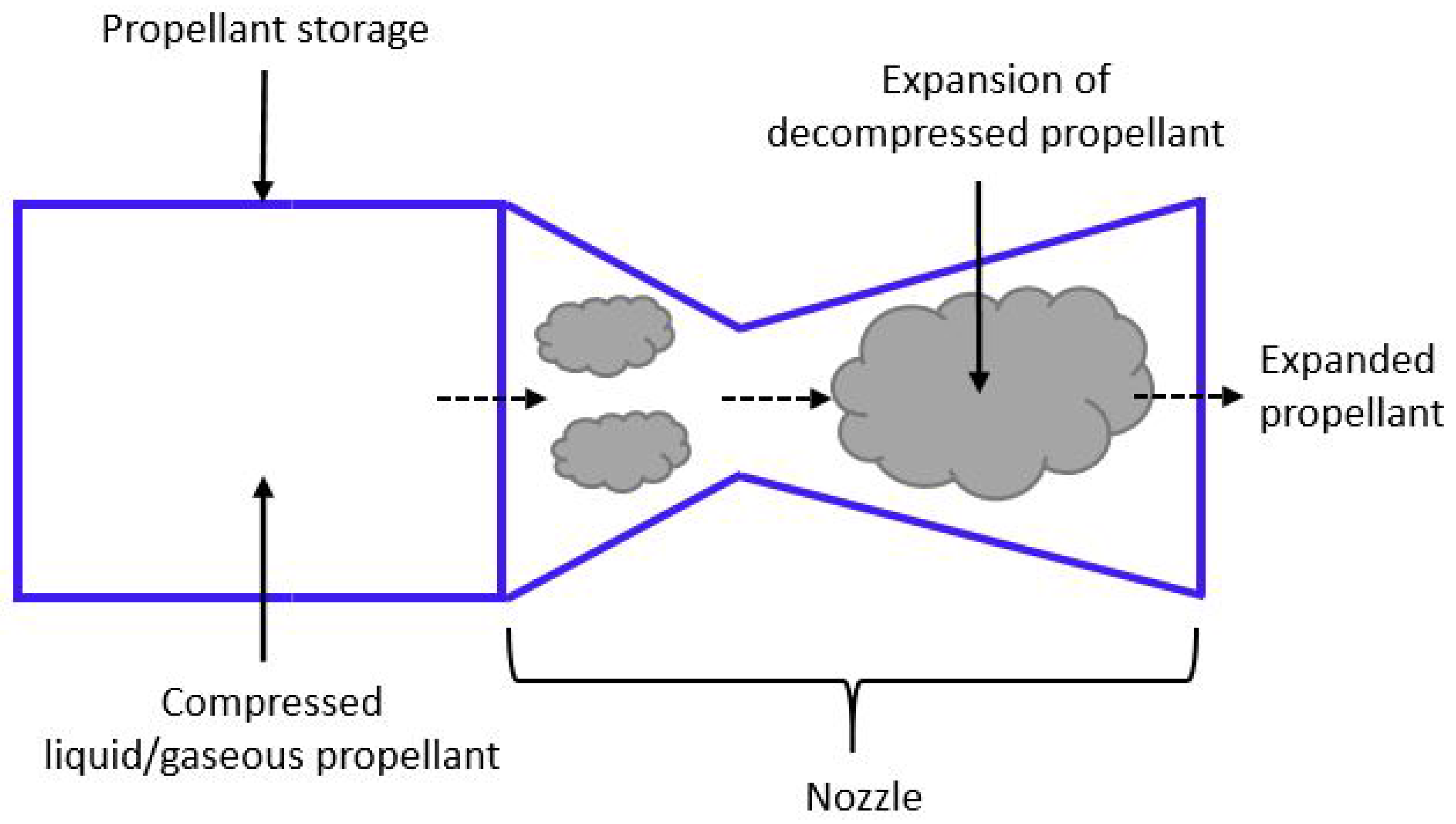
2. Cold Gas Propulsion (CGP) Systems

2.1. Operating Principle

A Cold Gas Propulsion System relies on the process of controlled ejection of compressed liquid or gaseous propellants to generate thrust. Due to the absence of a combustion process, a CGP system requires only one propellant (without an oxidizer), and hence can be designed with minimum complexity. The schematic of a typical CGP system is shown in Figure 1, and the main components include a propellant storage and a nozzle. The simpler design of a CGP system leads to a smaller system mass and lower power requirements for regulation purposes. However, these advantages come at the cost of a monotonically decreasing thrust profile over a period of time. The thrust produced is directly proportional to the pressure of the propellant inside the tank (propellant storage) and over the course of the mission, tank pressure decreases (due to propellant usage) resulting in a decrease of the maximum thrust that is generated by the system.
Specific impulse (shown in Equation (5)) of a CGP system mainly depends on the exit-to-chamber-pressure ( P e / P c ) and characteristic velocity ( C * ) [11]. The exit-to-chamber-pressure is related to the expansion of the propellant, while Poisson constant ( γ ) is the ratio of specific heats at constant pressure and constant volume. Characteristic velocity of a CGP system at any instant is a function of the velocity of propellant in Mach number [11]. Exit velocity (as shown in Equation (6)) is another important performance factor that not only depends on the exit-to-chamber-pressure, but also on the chamber temperature ( T c ) [11]. The mathematical relations summarizing these relationships are described below:
I s p = γ C * g o 2 γ 1 2 γ + 1 γ + 1 γ 1 1 P e P c γ 1 γ
v e = 2 γ T c γ 1 1 P e P c γ 1 2

2.2. Design Considerations and Technologies

A cold gas propulsion system can use either liquid or gaseous propellants, however, using a liquid propellant will lead to a reduction in the storage volume. The propellant selected should have high-density-I s p (Specific impulse/unit volume) in order to increase the longevity of the on-board propellant. In addition, lower storage pressure of the propellant facilitates the design of storage tanks with higher safety margin. The toxicity and the ease of availability of the propellant also impacts the design cost of a propulsion system during the on-ground manufacturing and assembly operations of the spacecraft. Therefore, using environment friendly propellants will lead to a decrease in costs incurred for safety measures, storage and transportation [12]. Liquid propellants provide the advantage of reduction in storage volume, however they can result in a de-stabilizing effect due to sloshing of propellant inside the tank [13]. While no specific sloshing prevention technology is available for CubeSats, special anti-sloshing baffles technology has been used in a micro-propulsion system of a larger satellite; these baffles are used to restrain the flow of propellant and have been used in the SNAP-1 propulsion system developed by Surrey Satellite Technology Ltd. (SSTL), Guildford, UK for the Giove-A mission [12].
A recently studied concept called solar thermal propulsion system has the potential of utilizing solar energy in improving the performance of CGP systems. In this system, concentrated solar energy is used to directly heat the propellant. As the propellant enters the nozzle at an elevated temperature, a significantly enhanced thrust and an increased specific impulse relative to a regular cold gas flow are observed. The solar thermal propulsion system concept was verified for a larger spacecraft, for instance, the orbital station-keeping scenario for a 200 kg spacecraft in a circular orbit was considered. The orbital parameters for this spacecraft were 600 km altitude, 28.5 degrees inclination and 1 km decay/day, and, it required a one minute burn of 1.9 N thrust to counter the orbital decay [14]. The 1.9 N burn was achieved with a specific impulse of 300 s, 0.64 g/s mass flow rate of propellant and an exit flow temperature of 1500 K. A major drawback of this technology is its dependence on direct solar illumination at the time of propulsive maneuvers [14]. Table 1 provides a summary of the performance parameters of the surveyed cold gas systems. As it is evident, CGP systems have been widely used on CubeSat missions; only one of the systems does not have CubeSat heritage but has flown on a larger satellite.

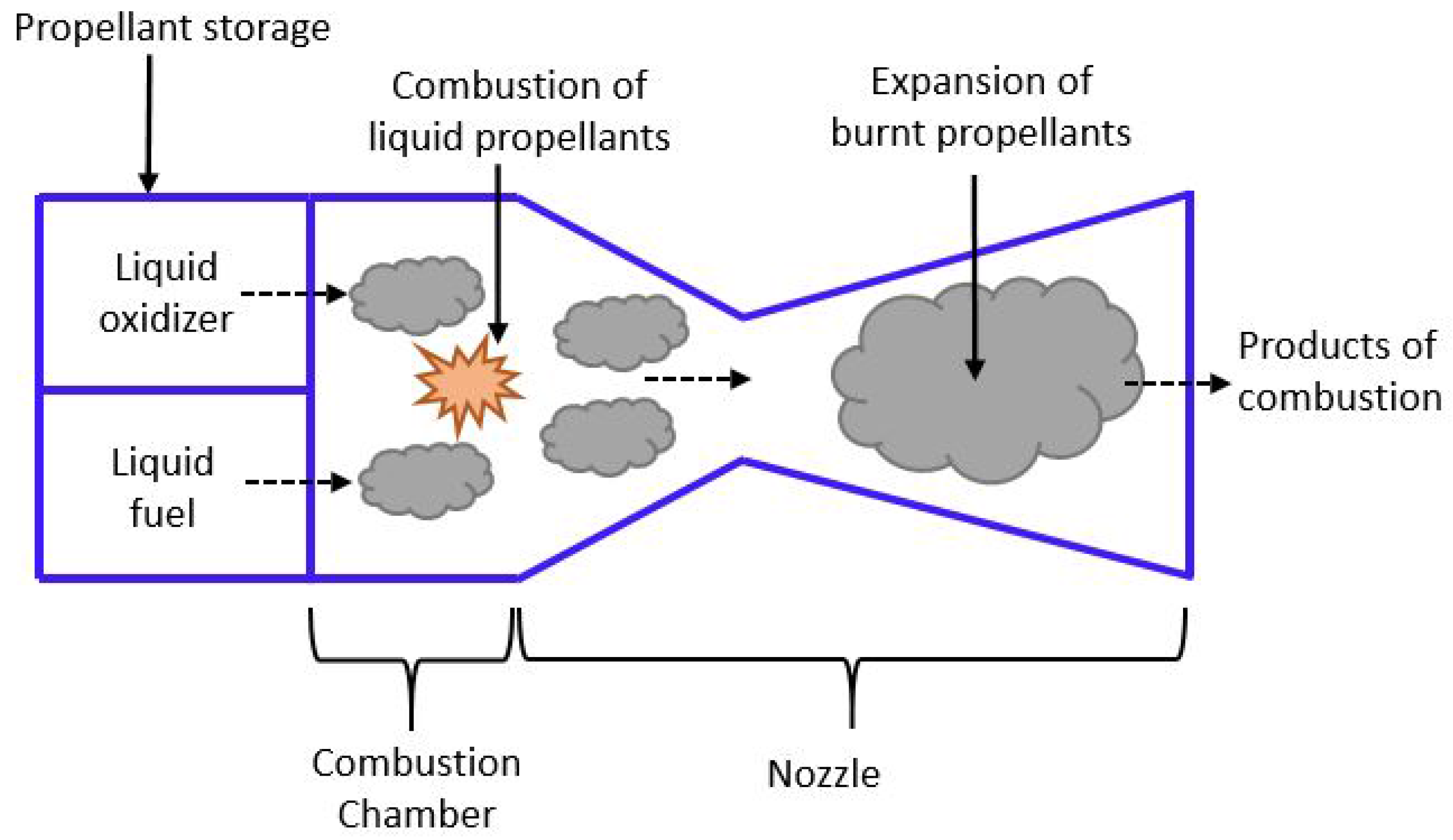
3. Liquid Propulsion (LP) Systems

3.1. Operating Principle

In a Liquid Propulsion System, thrust is generated by means of ejecting the gases formed during the process of combustion of liquid propellant(s). Depending on the mission requirements, a spacecraft can have LP systems with one (mono) or two (bi) propellants. Mono-propellant LP systems make use of a catalyst to decompose (ignite) the propellant and generate thrust. Decomposition process takes place when the propellant is injected into the combustion chamber through the catalyst bed [8]. Examples of mono-propellants are hydrazine and nitrous oxide [24] and examples of a catalyst are liquid permanganates, solid manganese dioxide, platinum, and iron oxide [8]. A bi-propellant LP system, on the other hand, comprises of both oxidizer and fuel. Combination of liquid oxygen and kerosene, or of liquid oxygen and RP1 are examples of bi-propellants that are widely used [24]. The fuel in the bi-propellant system can sometimes be used in a mono-propellant context with the inclusion of a catalyst. Either LP systems have primarily been used on larger satellites for high Δ v (orbit-raising) operations and a single propellant is typically used for low Δ v operations (station keeping). The schematic of a bi-propellant LP system is shown in Figure 2 and it primarily consists of a combustion chamber, nozzle and propellant storage for both oxidizer and fuel. Note here that the for the case of a mono-propellant system, the major components are propellant storage (only fuel), catalyst bed and the nozzle [8].
The thrust and specific impulse of an LP system can be obtained from the Equations (1) and (2) respectively. Exit velocity (shown in Equation (7)) of an LP system, like a CGP system is dependent on the exit-to-chamber-pressure-ratio ( P e / P c ) and combustion chamber temperature ( T c ) [8].
v e = 2 γ γ 1 T c 1 P e P c γ 1 γ ,
where γ is the Poisson constant and is the universal gas constant.

3.2. Design Considerations and Technologies

Liquid propulsion systems, like CGP systems, deal with issues related to storage and operational pressures of the propellant. To this end, the Maximum Expected Operating Pressure (MEOP), which is the highest possible pressure at which the propellant is expected to operate, is an important design parameter. MEOP of a propellant should be desirably high so that thruster performance (thrust, specific impulse) can be maximized [25]. Highly toxic propellants like hydrazine have been successfully used in larger spacecraft for over 60 years. Recently, there has been a global emphasis on the development and use of lower-toxic green propellants to reduce risks incurred due to contamination during laboratory testing and mission phases while in space. Green mono-propellants are less hazardous due to one of two reasons: either due to their benign toxicology even for probable levels of unintentional ingestion, or their low vapor pressure posing no significant risk of being inhaled. Many of the emergent green propellants (Sulfur Hexaflouride (SF 6 ), AF-M315E, Ammonium Dinitramide (ADN)) provide significant additional advantages like better physical characteristics (higher density), better performance for the propulsion system (higher thrust and specific impulse), and reduced thermal conditioning requirements for storage compared to hydrazine. However, they do pose a disadvantage with requiring higher preheat temperatures, higher than the typical 120–150 ° C of hydrazine thrusters [26].
Recently developed AF-M315E is a high performance Hydroxyl-Ammonium Nitrate (HAN) based green propellant (high mixture stability apart from being low-toxicity hazard) developed by US Air Force Research Laboratory (AFRL), Wright-Patterson Air Force Base, OH, USA. AF-M315E propellant has 50% higher density-specific-impulse (specific impulse/unit volume) than the hydrazine [27] and is still being tested for CubeSat applications; however, note that it is yet to fly on any spacecraft. The minimum storage and operating temperatures of AF-M315E potentially makes it a high interest application in cold environments where continuous thermal conditioning may not be feasible [26]. Additionally, a system using AF-M315E propellant will not likely encounter design issues and failure modes associated with control of mixture ratio of propellant, vapor diffusion and reaction, and oxidizer flow decay [27]. A major disadvantage of AF-M315E is that it is difficult to ignite due to its Ionic Liquid (IL) (high water content) form [26,28]. Experiments have been conducted with multiple catalyst systems to augment its ignitability, but room temperature ignition does not currently exist and the preheating process can consume large amount of energy (up to 15,000 J). These requirements on the energy consumption impose severe restrictions on spacecraft and even more so on CubeSats [28].
In order to cater to the needs of different CubeSat missions and to the increase their lifetime, micro-propulsion system developers have come up with form-factor customization based on the amount of on-board propellant that can be carried. MPS-120 CHAMPS, HPGP, BGT-X5 and VACCO/ECAPS are examples of micro-propulsion systems designed in multiple configurations varying from 0.5 U to 2 U. For a given system, the difference in configurations results mostly in the amount of propellant they carry. Note here that none of the above have flown on a CubeSat; however, HPGP micro-propulsion system has flown on two larger spacecraft. Table 2 provides a summary of the surveyed liquid propulsion systems and their performance factors. Note that, though HYDROS (developed by Tethers Unlimited, Bothell, WA, USA) is a hybrid electric/chemical propulsion system, however because the propellant is water it is summarized in the table below.

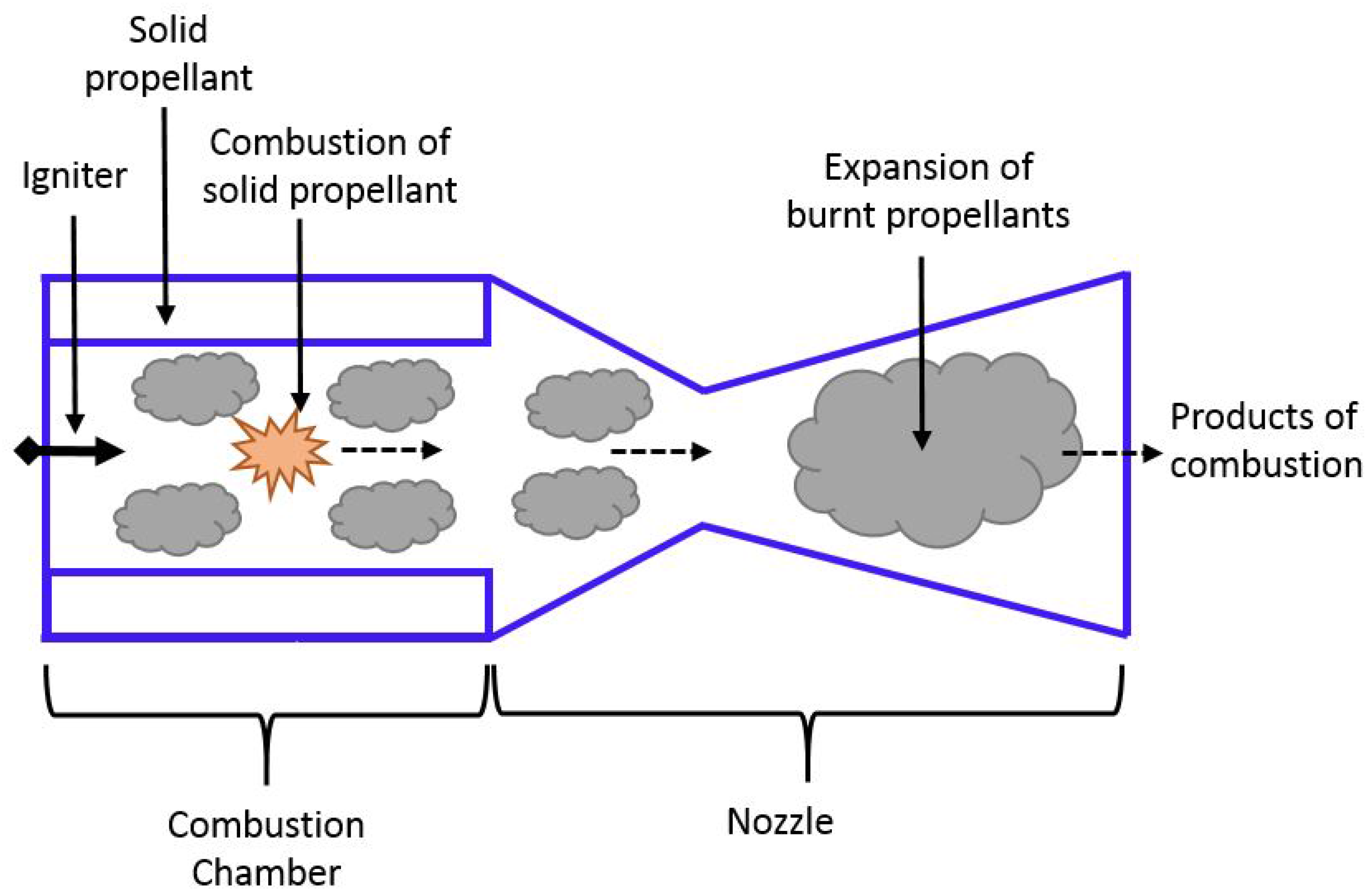
4. Solid Rocket Propulsion (SRP) Systems

4.1. Operating Principle

A Solid Rocket Propulsion System works on the principle of burning solid propellants and generating thrust by ejecting the gases formed during combustion. Similar to a LP bi-propellant system, an oxidizer is used in the SRP system. However, it differs from a LP system in a couple of ways: first, the solid propellants are stored within the combustion chamber itself; second, sloshing effects seen in LP systems are absent because both fuel and oxidizer are solids. Although SRP systems do not experience sloshing, the lack of control over propellant burn rate creates difficulty for thrust regulation [8]. The schematic of a SRP system is shown in Figure 3 and comprises of a combustion chamber that holds the solid propellant, an igniter that initiates the combustion process and a nozzle.
Considering that thrust regulation is difficult in SRP systems, burn rate can be used in the initial phase of system design to understand the combustion process because it governs the mass flow rate of hot gases generated during combustion. The burn rate (r) (shown in Equation (8)) is dependent on the chamber pressure ( P c ), temperature coefficient (a) and combustion index (n). Temperature coefficient is a non-dimensional empirical constant, while the combustion index describes the influence of chamber pressure on the burn rate. For a propulsion system equipped with a de Laval (CD) nozzle, the characteristic velocity (C * ) (shown in Equation (9)) relates to the efficiency of the combustion process and is independent of nozzle characteristics [8]. The thrust, specific impulse and exit velocity of an SRP system can be calculated the same way as it is done for LP systems from Equations (1), (2) and (7) respectively. The mathematical relations summarizing burn rate and characteristic velocity are described below:
r = a P c n
C * = P c A t m ˙

4.2. Design Considerations and Technologies
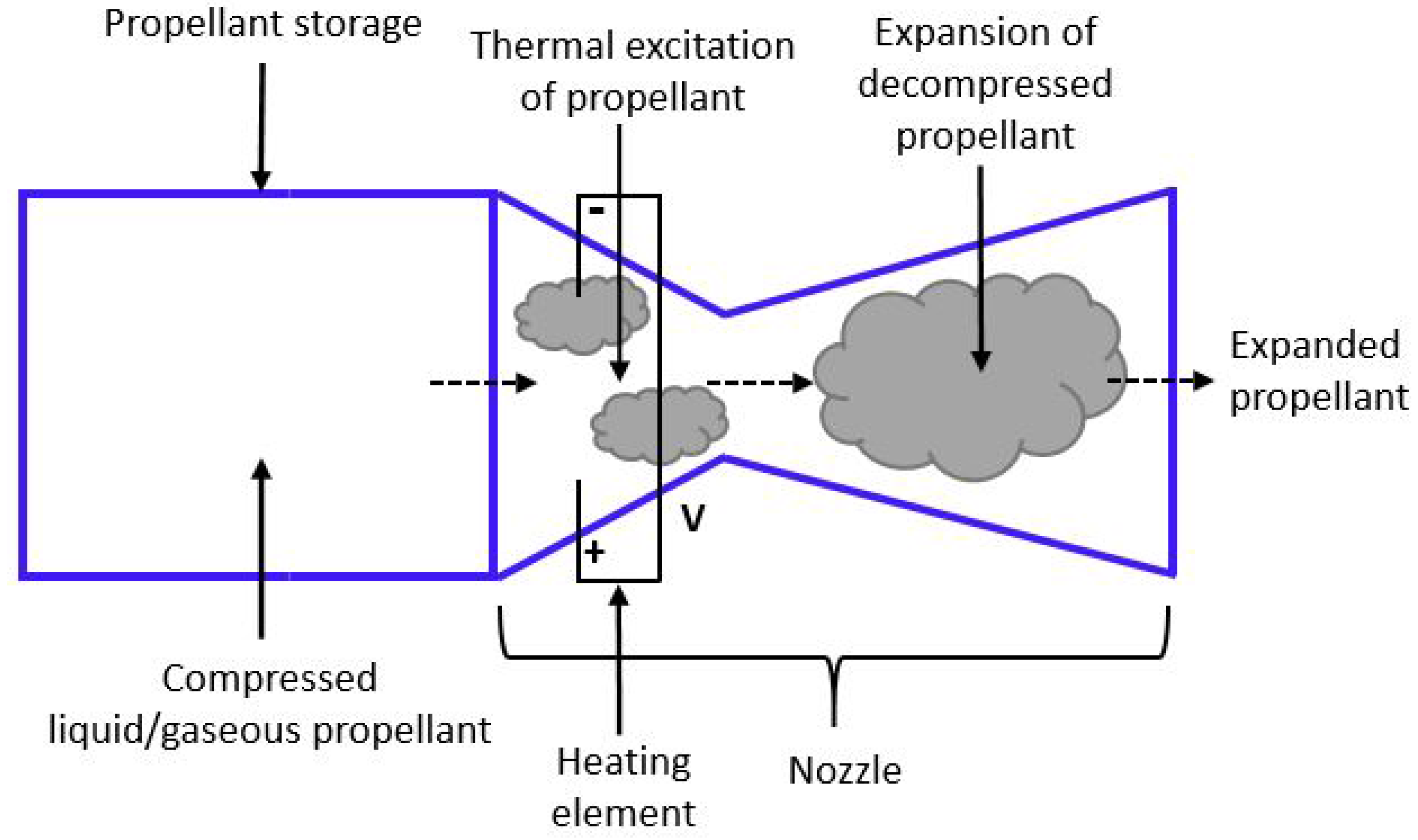
To overcome the issues with thrust regulation in SRP systems, a unique addition (to the existing SRP system design) was proposed and designed by Aerospace Corporation, El Segundo, CA, USA for the I s p 30 s Motor SRP system. This addition consists of an external movable mass (pitch/yaw system) with 8 jet paddles. The jet paddles are located just aft of the nozzle, and constitute rectangular moving arms (plates or slabs) with one of their faces exposed to the exhaust flow. Thrust regulation occurs by controlling the orientation of the paddles and imparting desired directionality to the flow [39]. Note that this technology could potentially lead to benefits for other micro-propulsion systems as well, specifically LPS.
A disadvantage of SRP systems is their one-shot use owing to a lack of control over propellant burn rate. To mitigate this disadvantage, a system of hundreds of Solid Propellant Micro-thrusters (SPMs) has been proposed in Ref. [40]; these micro-thrusters can be used by forming a tightly spaced matrix (within the constraints of available external surface area). In SPMs, solid energetic propellant is burnt (during combustion process) and the resultant gases are accelerated through micro-nozzles. The size of the thruster can be modified to suit the thrust requirements and programmable thrust delivery can be achieved via simultaneous or sequential firing of multiple thrusters [40]. A typical SRP micro-thruster makes use of MEMS technology and comprises of several laminated layers containing a combustion chamber, an igniter, a nozzle, and a seal [41]. Combustion chamber stores the solid energetic-propellant and igniter section heats the propellant by means of a resistive heating element. Silicon or nichrome are generally used as materials for the heating element [41]. Nozzles are designed to meet mission-specific thrust requirements and de-Laval (CD) nozzles are commonly chosen for their higher performance. The seal comprises of an epoxy or similar material or mechanisms. Also, silicon wafer is used in these micro-thrusters because it improves the ignition efficiency by minimizing the current leakage [42]. In addition to addressing the issue of a lack of control over propellant burn, SPMs avoid additional external-surface-area requirements owing to the use of a traditional nozzle (instead micro-nozzles are distributed over the surface of the spacecraft). Furthermore, SPMs provide the capability to generate differing torque values depending on thruster distance from the center of mass.
An alternative technology that provides improvement of burn rate regulation was proposed by Digital Solid State Propulsion (DSSP), Reno, NV, USA through the invention of a new Electric Solid Propellant (ESP). ESP is a Hydroxyl Ammonium Nitrate (HAN) based Green Mono-propellant (GEM) and offers higher theoretical performance than AF-M315E propellant (discussed earlier in LP systems section). This new technology is inherently safe because ignition is possible only through continuous supply of electrical power, thereby reducing the chances of flames generated due to accidents and it has the potential to be used as propellant in both chemical and electrical propulsion systems [43]. This technology has flown on a larger satellite; SPINSAT, a spherical satellite with 22 inch diameter and a mass of 57 kg, was launched in 2014 and housed 72 DSSP thrusters [44].
Many inexpensive alternate propellants have been researched for SRP systems and recently, aluminum wool as a propellant, along with the mixture of sodium hydroxide and water as an oxidizer, was tested and was found to produce a thrust of 32 mN and specific impulse of 45 s. A major advantage of these propellants is that they are low cost, easy to handle, and can be stored over a long duration without any decomposition [45]. Table 3 provides a summary of the surveyed SRP systems and their performance parameters. None of the mentioned systems have a heritage of flying on a CubeSat mission, however, as already indicated, one of these, the DSSP CAPS-3 propulsion system has flown on the SPINSAT mission.

5. Resistojets

5.1. Operating Principle

In a resistojet, the propellant is passed through a heat exchanger (or heating element) where it is super-heated and ejected through an expansion nozzle [48]. For instance, laboratory experiments have shown exit temperatures of 600–1050 ° C for methanol and 300–1175 ° C for ammonia propellants [49]. The heating process reduces the gas (propellant) flow rate from a given upstream pressure through a given nozzle area, thus leading to the increase in specific impulse that is proportional to the square root of temperature as depicted in Equation (11) [50]. The working principle of a resistojet is similar to that of a CGP system except that the propellant is heated before the expansion process. Because of the propellant’s high energy (gained by heating), an exhaust velocity much greater than that of a CGP system is achieved in a resistojet [48]. Exit velocities of micro CGP systems range between approximately 300–700 m/s [51,52], while those of micro resistojets are about approximately 2.2 km/s [53]. A major drawback of resistojets is that their performance (thrust, I s p ) is limited by the melting temperature of the heating element used. In addition, power and thermal losses during heating of the element contribute to the inefficiency of resistojets [54]. The schematic of a resistojet propulsion is shown in Figure 4, and the main components include propellant storage, heating element and nozzle.
The thrust (shown in Equation (10)) produced by the propellant at stagnation pressure also depends on stagnation number density of propellant ( n o ) in m 3 , stagnation temperature ( T o ) and the probability ( χ ) of a molecule exiting the expansion slot area ( A o ). Specific impulse (shown in Equation (11)) is a function of the stagnation temperature, and the mass of the propellant (m) [55].
τ = A o n o k T o 2 χ
I s p = π k T o 2 m 1 g o ,
where k is the Boltzmann constant and g o is the acceleration due to gravity at sea level.

5.2. Design Considerations and Technologies

Resistojets with a variety of propellants have been used on larger satellites, and like any other systems with liquid propellants, they have experienced issues due to sloshing within the tanks [56]. Free Molecule Micro Resistojet (FMMR) developed with water as the propellant is one of the systems that can potentially counter these issues [56]. FMMR is a low cost, low power consumption and low mass MEMS fabricated resistojet that operates by heating a propellant gas as it expands through a series of slots [56,57]. There are three major advantages of using water as the propellant: first, water is stored as a liquid and can save the volume occupied by the propellant due to its high storage density; second, due to its lower molecular mass, water propellant can improve the specific impulse; third, water has sufficiently high vapor pressure at typical smallsat (<10 kg) on-orbit temperature because of which it can be directly used to produce thrust without pre-vaporization [56]. During laboratory experiments of FMMR, it has been demonstrated that the effect of the propellant sloshing on spacecraft attitude stability is minimal [56].
Resistojets are known to provide lower thrust and are mainly employed for attitude control on larger satellites. CubeSat High Impulse Propulsion System (CHIPS) resistojet developed by CU Aerospace, Champaign, IL, USA and VACCO Industries Inc., Huntsville, AL, USA. CHIPS offers dual mode operation: first, warm fire mode (30 mN thrust and 82 s I s p ) for high thrust operations; second, cold fire mode (19 mN thrust and 47 s I s p ) for low thrust (attitude control) operations [58]. Table 4 provides a summary of the surveyed resistojets and their performance parameters. None of these resistojets have a heritage of flying on a CubeSat mission, however one of them has been used on a bigger spacecraft. Other resisto-thermal propulsion systems such as Pulsed Electrothermal Thrusters (PET), microwave electrothermal thrusters and arc jets are mentioned in the Section 11 of the current paper.

6. Radio-Frequency Ion Thruster (RIT)

6.1. Operating Principle

Radio frequency ion thrusters belong to a subset of gridded ion thrusters that generate thrust by accelerating the ionized propellant (plasma) through an electrostatic grid. Electron bombardment and microwave thrusters are some of the other gridded ion thrusters [63]. In RITs, the stored propellant is let into the discharge chamber where it is ionized (and becomes plasma) by means of Radio Frequency (RF) power (from RF coils). The ionized propellant is then extracted (from the discharge chamber) and accelerated by a series of grids (ion optics) called screen and accelerator grids. The screen grid extracts propellant cations (for instance, Xe + , Kr + ions) from the ionized plasma and directs them downstream towards the accelerating grid [63]. Bigger RF ion engines that are used on larger spacecraft also have a third grid called the decelerator grid, however the it is typically not used in CubeSat propulsion systems. A neutralizer cathode, present on the exterior of the thruster in all ion engines, provides electrons to neutralize the ionized propellant that is emitted from the thruster [63]. The specific impulse of a gridded thruster can be varied by changing the voltage that is applied to the accelerating grids [64]. Electron bombardment and microwave thrusters are some of the other types of gridded ion thrusters where the ionization occurs due to electron bombardment with the neutral propellant and microwave power respectively [63]. The schematic of an RF Ion propulsion system is shown in Figure 5 that includes the propellant storage, RF coil, discharge chamber, grids (screen and accelerator) and a neutralizing (external) cathode. Ion thrusters are characterized by high thruster efficiency (60% to >80%) resulting in high specific impulse (from 2000 s to over 10,000 s) [63]; however, they have been plagued with issues that are caused by cathode wear [65] and contamination over prolonged usage [66]. Various types and composition of contamination are explained in the following sub-section.
The ion exhaust velocity (shown in Equation (12)) and thrust (shown in Equation (13)) are both functions of the charge of propellant ion (q), mass of propellant ion ( m i o n ) and ion accelerating voltage ( V i ). Ion engines use heavier elements (elements with higher atomic mass) as propellants because the thrust generated is proportional to mass of the ion (propellant). Thrust, however, also depends on the ion beam current ( I i ) [63]. Specific impulse (shown in (14)) is a function of ion accelerating voltage and mass of ion [63]. The performance factors of ion engines are explained below with their mathematical equations:
v e i = 2 q V i m i o n
τ = 2 m i o n V i q I i
I s p = 1.417 × 10 3 γ c η m V i m i o n ,
where η m is the thruster mass utilization efficiency and γ c is the total thrust correction factor.

6.2. Design Considerations and Technologies

Ion thruster operation may lead to several interactions between the thruster and the spacecraft instruments namely, ionized propellant (plasma), contamination and field interactions. Plasma and contamination interactions comprise of two types of efflux: propellant efflux composed of propellant ions, neutralizing electrons, non-ionized propellant, and a low-energy charge exchange plasma; non-propellant efflux composed of material sputtered from the thruster components and the neutralizer due to ion bombardment. The field interactions are the result of RF field, electrostatic accelerators and the interaction of the plasma plume with the ambient (space) environment. Contamination effects incurred can be mitigated by the use of inert propellants like xenon and krypton, however, it still leaves out the issues due to the plasma interactions [66].
Hollow cathode tubes are regularly used in electron-bombardment ion engines to provide electrons for the neutralization of the ion beam. The hollow cathode assembly consists mainly of the cathode tube that has an insert (electron emitter), orifice plate (present downstream of thruster) that facilitates the flow of exhaust plume, heater that raises insert temperature and a keeper electrode. Major functions of a keeper electrode are to facilitate turning on the cathode discharge, to maintain the cathode temperature and operation when discharge or beam current is interrupted temporarily, and to protect the cathode orifice plate and external heater from ion bombardment [63,67]. It is of very high importance to study and analyze the wear of discharge cathodes as their failure is deemed to be one of the major life-limiting mechanisms of ion thrusters. The following wear processes are generally seen in discharge cathode assembly: failure of the heater, cathode orifice plate, and keeper electrode [68].
A new field of materials science called Solid State Ionics (SSIs) can offer solutions to overcome issues with the production and delivery of ions to their extraction sites without complications of plasma discharge chamber and all of its essential components [69]. SSIs deal with the preparation, characterization, theory, and application of solids that support ionic conduction [70]. SSI conductors are currently the key elements in the oxygen sensors used in automobile exhaust systems, lithium ion batteries, solid oxide fuel cells, electro-chromic windows and in some superconductors [69]. Table 5 provides the summary of the surveyed RF ion thrusters along with their performance factors. None of these ion thrusters have a space heritage, while one of them is scheduled to fly on the Lunar IceCube mission in 2018.

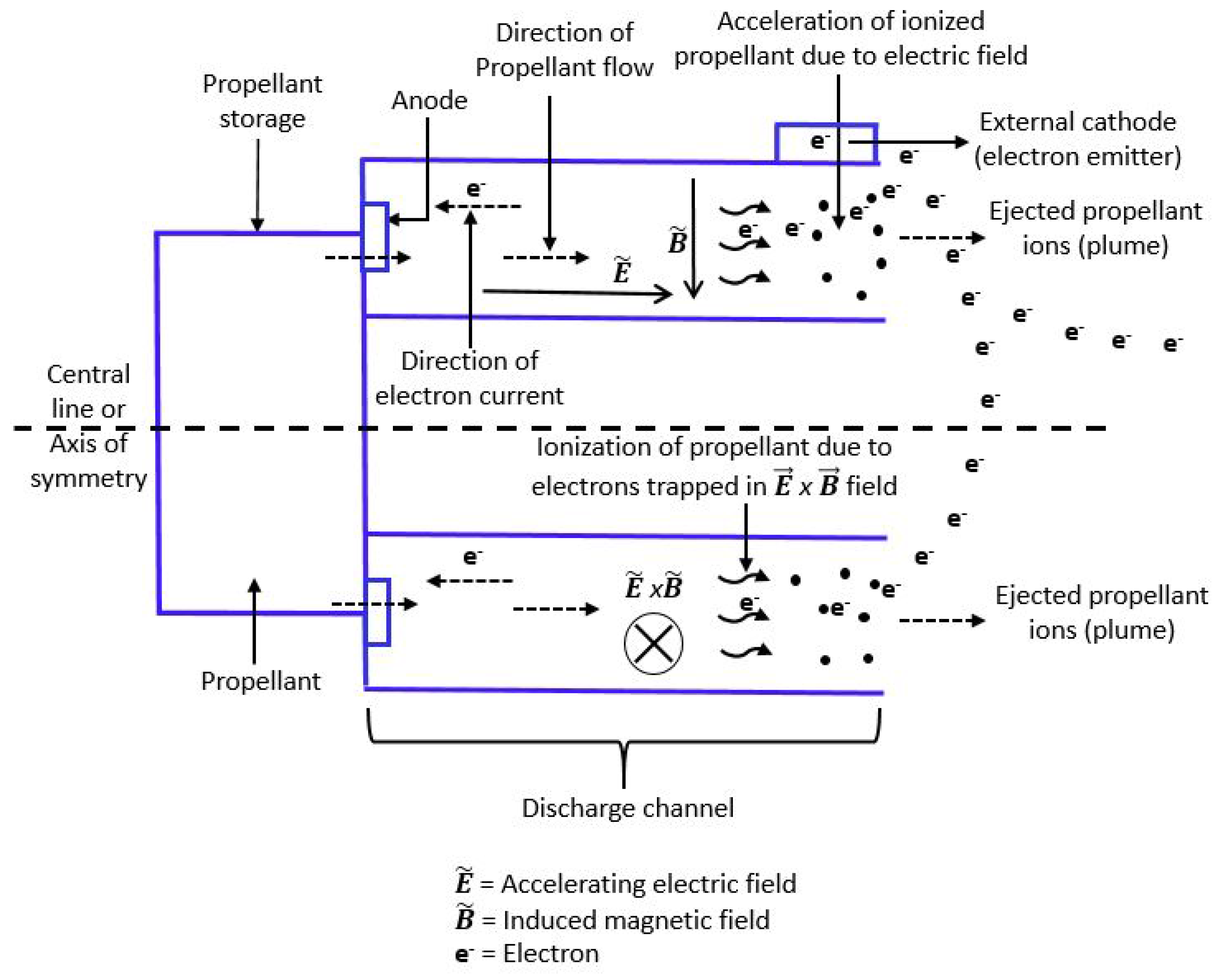
7. Hall Effect Propulsion/Hall Thrusters

7.1. Operating Principle

Hall Thrusters are electrostatic devices [63] that generate thrust by first ionizing and then accelerating the propellant in mutually perpendicular electric and magnetic fields. These thrusters work on the principle of the well known Hall Effect that states the following: when electric current is applied to a conductive material (propellant) placed in mutually perpendicular electric and magnetic fields, a potential difference is developed that is perpendicular to the applied electric and magnetic fields [74]. The schematic of a Hall thruster is shown in Figure 6 that includes propellant storage, discharge channel, external cathode, anodes and the magnetic field generator. The applied magnetic field is radial, while the accelerating electric field (acting from anode towards cathode) is axial [63]. Note that Hall thrusters, unlike gridded ion thrusters, do not have the grid system (series of grids), instead the grids are replaced with a strong magnetic field perpendicular to the flow of ions. This magnetic field reduces the mobility of electrons coming from the external cathode, thereby restraining their flow towards anode in the accelerating electric field [63,75,76]. Hall thrusters have many advantageous features like high specific impulse (higher than most systems except ion engines), higher thrust density [77] and simplicity in design (when compared to gridded ion engines due to lack of accelerator grids) [78]. However, they also face some challenges with erosion of magnetic circuitry due to discharge plasma and lower efficiency (6–30% at 0.1–0.2 kW and 50% at 1 kW) [79].
The performance factors for Hall thrusters like ion exit velocity (shown in Equation (12)), thrust (shown in Equation (13) ) and specific impulse (shown in Equation (14)) are the same as the ones for RITs [63].

7.2. Design Considerations and Technologies

Recall that, in a typical Hall thruster, magnetic field ( B ~ ) is applied across an accelerating electrical discharge ( E ~ ) allowing to trap the electrons in the Hall effect ( E ~ × B ~ ) direction. The anode is located at the base of the discharge channel, and also serves as the source of the neutral propellant. An external cathode is present outside the discharge channel and provides electrons that move towards the anode across the radial magnetic field [63,80]. When the electrons enter the magnetic field, they spiral around the thruster axis in the ( E ~ × B ~ ) direction and their interaction with the incoming propellant leads to the ionization of the propellant [63].
Hall thrusters can be classified into two types: magnetic layer and anode layer thrusters. The magnetic layer thrusters have continuous and extended acceleration zones for sufficient ionization and stability. They also have a ceramic wall, and their acceleration channel length is longer than the channel width. On the other hand, Hall thrusters with anode layer have a narrow acceleration zone (length of the discharge channel is shorter compared to the channel width) [81,82]. The electron temperature of anode layer thrusters is higher than that of magnetic layer thrusters due to the lower electron energy losses [81].
Similar to ion engines, the Hall thrusters make use of heavy elements as propellants, for instance, xenon (Xe), krypton (Kr), iodine (I), bismuth (Bi) and argon (Ar). Of these, xenon has been favored for its lower ionization energy, higher atomic mass and easy storage. However, it is expensive to purchase and to perform ground tests with xenon [83]. Many cheaper alternatives to xenon exist, but further experiments have to be conducted to prove their usefulness [84].
Lifetime of a Hall thruster is mainly limited by the erosion of the components protecting its magnetic circuitry from discharged plasma (ionized propellant). Once the magnetic poles are exposed over time, further degradation or overheating may occur, affecting the nominal magnetic field and thereby the thruster’s performance. In order to determine the lifetime of a Hall thruster, apart from the usual long duration qualification tests, shorter duration experiments are also performed so that the erosion behavior can be characterized enabling the extrapolation of the thruster lifetime [85].
In comparison with gridded ion thrusters where ion beam can be properly controlled, it is more difficult to control the same in Hall thrusters leading to the wall erosion. This issue has troubled Hall thrusters for many decades, ever since they were introduced for larger spacecraft. Wall erosion is mainly caused when the the ions are driven towards the wall material because of elevated parallel component of electric field and the high electron temperature. Recently, a new technique called Magnetic Shielding (MS) was proposed that could potentially eliminate wall erosion in Hall thrusters. It is to be noted that, the magnetic and electric fields that are supposed to be mutually perpendicular are not so when under electron pressure [86]. When the walls are magnetically shielded, the electric field component parallel to the wall is nearly eliminated, resulting in the decrease of ion bombardment on the walls. For instance, when a magnetically shielded Boron Nitrate wall was used at an ion threshold energy of 25 V, the computed wall erosion rate was found to be approximately 600 times lower at the inner wall (wall closer to central line) than when unshielded. The outer wall on the other hand was found to experience zero erosion [86].
Characterizing the performance of newly designed Hall thrusters is often a tedious and expensive process [87]. To save time and cost incurred for characterization, scaling/sizing relations were introduced. It was found from a study that, for small Hall thrusters, the propellant mass flow rate and the applied power were proportional to the channel length, while the magnetic field strength was inversely proportional to the channel length. In other words, as long as the power of a larger Hall thruster is available, the mass flow rate of propellant, strength of applied magnetic field and channel length can be determined [88]. Table 6 provides the summary of the surveyed Hall thrusters and their performance parameters. None of the listed engines have a CubeSat heritage, however one of them has flown on two bigger satellite missions as a secondary propulsion system.

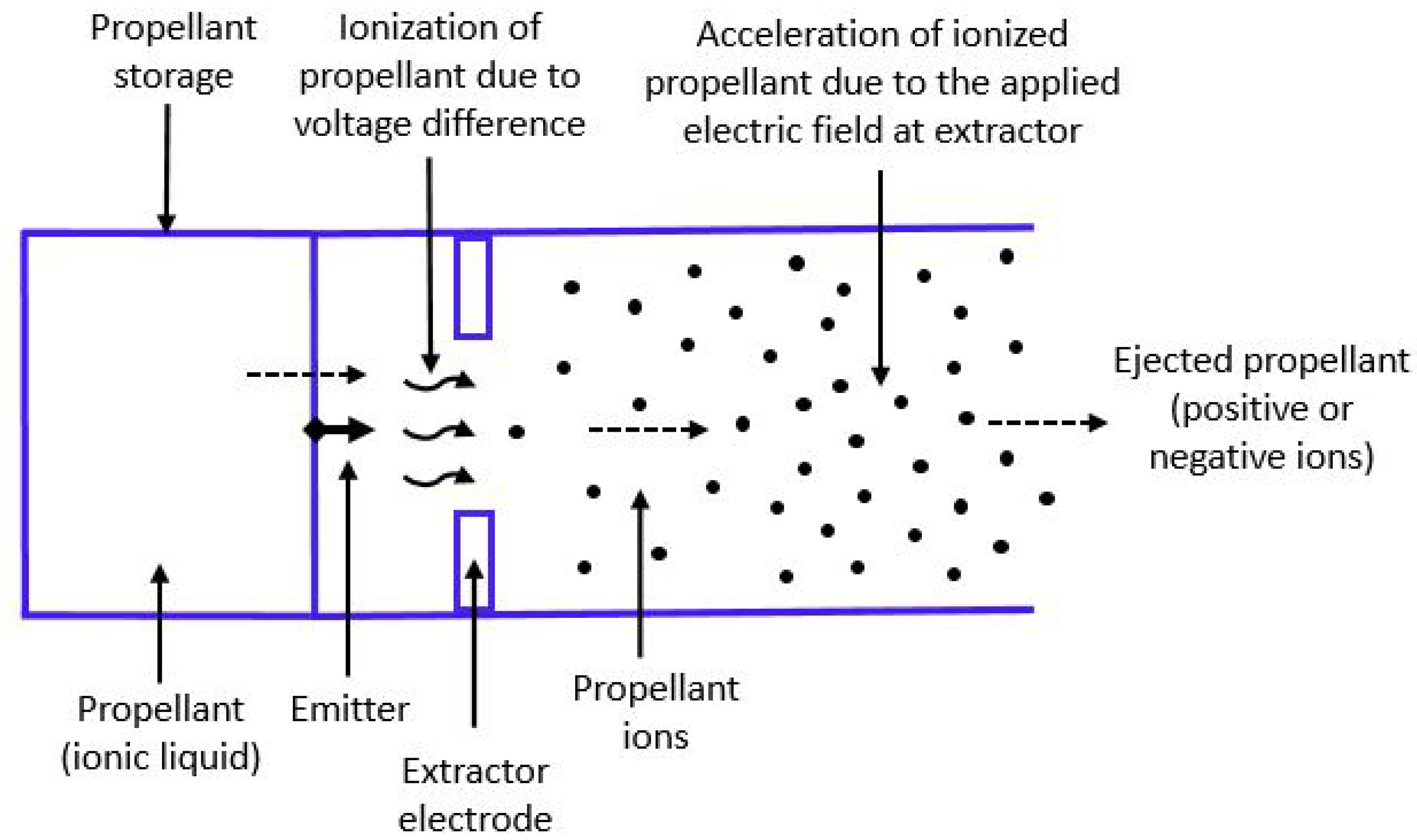
8. Electrospray Propulsion System/Electrospray Thrusters

8.1. Operating Principle

Electrospray thruster is a plasma-free electric propulsion system [93] that works on the principle of electrostatic extraction and acceleration of charged particles (ions) from a liquid (propellant) surface to produce thrust. Their fundamental working mechanism is based on a process by which the conductive liquid surface of the propellant is deformed into a sharp cone-shaped meniscus called Taylor Cone; when a certain threshold of the electric potential is surpassed, ions are extracted from the cone’s apex [94,95,96]. Electrospray thrusters accelerate positive or negative ions, respectively generating either a positive or negative ion beams thereby eliminating the need for an external cathode to neutralize the ejected ions unlike in plasma propulsion devices (ion and Hall thrusters) where an external cathode is essential [97]. The propellants used for electrospray thrusters are usually ionic liquids, and their negligible vapor pressure serves as an advantage by resolving the need for propellant pressurization and helps with system miniaturization [96]. The schematic of an electrospray propulsion system is shown in Figure 7, and the major components comprise of propellant storage, emitter and extractor electrode. The performance of an electrospray thruster can be varied by changing the voltage passed through th emitter and the extractor electrodes [93].
In an electrospray thruster, the mass-to-charge ratio plays an important role in determining the exit velocity and thrust. The average mass-to-charge-ratio q m i o n (shown in Equation (15)) is inversely proportional to the density ( ρ ) of the propellant ion/droplet and the volume flow rate (Q) of ion/droplet. The exit velocity (described in Equation (16)) is a function of the square root of ion accelerating voltage ( V i ), ion beam current ( I i ) and average mass-to-charge-ratio. The thrust (shown in Equation (17)) is a function of ion accelerating voltage, ion beam current and mass flow rate of ions ( m ˙ i o n ) [98]. The underlying mathematical relations summarizing the relationships are given below:
q m i o n = 1 ρ Q
v e i = 2 V i I i q m i o n = 2 V i I i ρ Q
τ = m ˙ i o n v e i = 2 V i I i m ˙ i o n

8.2. Design Considerations and Technologies

In an electrospray thruster, typically, the extraction of charged particles is done through two regimes: the cone-jet regime, in which the meniscus (of the propellant) breaks up into droplets; and the ionic regime where pure ions are extracted. The specific impulse observed in ionic regime is greater than in cone-jet regime [96]. A thruster is typically designed to operate in only one of the two regimes, and the regime defines the specific thruster: either a colloid thruster or a field emission thruster.
Electrospray thrusters use ionic liquids as propellants as they do not require heating, have low operating voltage, high conductivity in the pure state and negligible vapor pressure [99,100]. Formamide, propylene carbonate, water, Tri-Ethylene Glycol (TEG) solutions doped with Sodium Iodide (NaI), 1-Ethyl-3-Methyl Imidazolium bis(tri-fluoro-methyl-sulfonyl) imide ([Emim][Im]), formamide, tri-butyl phosphate, 1-Butyl-3-Methyl Imidazolium Di-Cyanamide ([Bmim][DCA]) and 1-Ethyl-3-Methyl Imidazolium Tetra-fluoro-borate (EMIBF4) are some of the propellants used in electrospray systems [93,100,101,102,103]. Liquid metals like cesium, gallium and indium have also been used as propellants due to their high atomic mass and a low ionization potential [104].
An individual electrospray emitter operates in the milli-watt (power) and generates thrust in the order of micro-newtons, therefore, an array of emitters is required to form the thruster that can yield the desired thrust [93,100]. Conventionally, electrospray thrusters have used metallic emitters, but pure silicon has also been used to make emitters with the help of Deep Reactive Ion Etch (DRIE) technology and micro-fabricated components [105]. However, using silicon poses a problem with being able to conduct electrons to or from the sprayed fluid (propellant). This problem can be countered by either providing a conductive film surface over the silicon (by deposition process) or by highly doping the silicon to create a conductive silicon material [105]. Table 7 provides the summary of surveyed electrospray thrusters and their performance parameters. One of the listed systems has a CubeSat heritage and another one has flown on a bigger spacecraft.

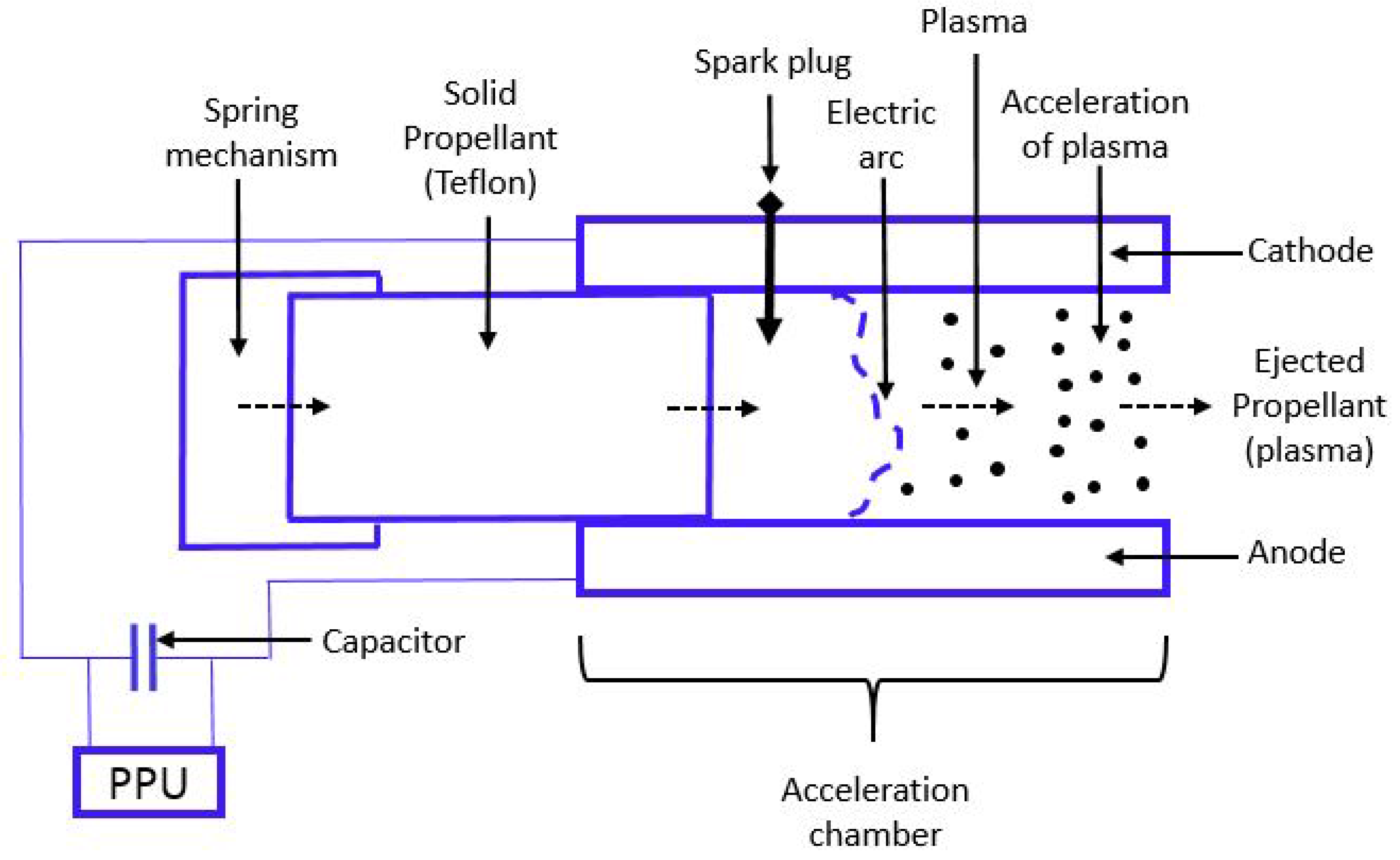
9. Pulse Plasma Thruster (PPT)

9.1. Operating Principle

Pulsed Plasma Thrusters (PPTs) operate by creating a pulsed, high-current discharge across the exposed surface of a solid insulator (for instance, Teflon) that serves as a propellant. The arc discharge ablates (sublimates/vaporizes) the propellant material from its surface, thereby ionizing and accelerating the propellant to high speeds. A current pulse lasting few micro-seconds is generally driven by a capacitor that is charged and discharged approximately once every second [110]. The schematic of a PPT is shown in Figure 8 containing a spring loaded mechanism, propellant, capacitor, anode, cathode, acceleration chamber and a spark plug. During the process of propulsion, the spring feeds the propellant (usually solid) between the two electrodes (anode and cathode) and the spark plug is simultaneously fired (through a small discharge) to raise the electrical conductivity of the acceleration chamber. Now, the electric current from Power Processing Unit (PPU) flows to the electrodes through the capacitor and then into the arc, thereby completing a current loop and simultaneously generating a magnetic field. The electric arc formed ablates the propellant and ionized plasma is formed. The plasma is then accelerated due to Lorentz Force generated by electric arc and the induced magnetic field [111].
The advantages of a PPT are its ability to provide small impulse bits for precision maneuvering, robustness by programming impulse bits to cater to mission needs, design simplicity owing to the ability of using wide variety of propellants (solid/liquid), and its ability to maintain constant specific impulse and efficiency over a wide range of input power levels. However, these advantages come at the cost of issues that result due to electrode erosion, presence of macro-particles in the plume due to non-uniform ablation and very low thruster efficiency [111,112,113,114,115].
The thrust (shown in Equation (18)) produced is calculated from the law of conservation of momentum. For any electric thrusters, Lorentz Force describes the relationship between the force (thrust) produced due to charged particles moving through a self induced magnetic field. Thrust produced also depends on the charge of ions (q), sum of all collision forces per particle (propellant) over all particles ( ( P i ) k ) and particle velocity ( u ~ i ). The effective exit velocity (shown in Equation (19)) of the ionized propellant is a function of the thrust generated and the mass flow rate of propellant ( m ˙ ) and efficiency ( η ). Effective exit velocity can also be calculated in terms of the radius of anode ( R a ) and radius of cathode ( R c ). The specific impulse of a PPT can be obtained from the Equation (2) [116].
τ = m i o n d v ~ i d t = q E ~ + u ~ i × B ~ + Σ ( P i ) k
v e = τ m ˙ η = 1 η μ 0 4 π l n R a R c ,
where μ 0 is the permeability of free space.

9.2. Design Considerations and Technologies

Analyses indicate that 45 ± 11 % of ablated mass per pulse in a PPT is expelled at negligible speeds relative to the effective plume exhaust velocity (1500 m/s) and on a time scale longer than the 0.5 s primary discharge [117]. Due to delayed ablation and particulate emissions, PPTs have a very low efficiency (10–20% [116]) [114]. Particulates, sometimes referred to as Macro-Particles (MP), are emitted during a pulse and may interact with the surrounding plasma. In addition, particulate emissions consume about 40% of the total propellant mass, while contributing only 1% towards the total thrust generated [114]. In the case that late ablation is diminished or totally prevented, the specific impulse and efficiency of the thruster can be substantially raised [115].
Teflon is a widely used inert and non-toxic [118] solid propellant in PPTs, and as a result, it is of great importance to study the phenomena that occur with its use. One such phenomenon is the charring of electrodes. It was experimentally observed that current density and Teflon surface temperature have their maxima near the electrodes due to their preferential ablation. Microscopic analysis of the charred area has shown the presence of carbon due to the carbon flux returned from the plasma. In some cases, metal layers originating from electrode erosion were also found under the carbon char [113].
Spark (igniter) plugs are normally used in a PPT to provide a large supply of free electrons to initiate an electric discharge between the electrodes across the exposed surface of the propellant (Teflon). They are extensively used because of the unavailability of any other suitable alternatives. Various studies are being conducted to prove the feasibility of shining an Infra-Red (IR) laser pulse on the thruster’s backplate or a self-triggering design where the voltages in the electrodes can exceed the breakdown voltage of the discharge gap. Although the proposed studies are effective theoretically, they seem to pose design challenges for spacecraft usage [119].
Development of an efficient pulsed plasma accelerator is a challenging proposition due to the problems with propellant conversion efficiency hindering the breakdown of propellant gas. Additional challenges result due to electrode erosion and the difficulty in transferring all energy input to the ionized propellant (gas). Planar Pulsed Inductive Thruster (PIT) is a modified PPT technology first developed in the early 1960s to overcome the existing issues (efficiency and electrode wear) with PPTs. PIT is an electrode-less system that could accommodate a wider variety of propellants like CO 2 , ammonia, hydrazine and H 2 O. PITs have also demonstrated their operation with efficiency being relatively constant over a wide range of I s p . They potentially process high levels of power that result in relatively high thrust using a single thruster [112].
Vacuum arc discharges that ablate and consume cathode material (solid propellant) in vacuum produce fully ionized plasma jets having high velocity. Such devices are called Vacuum Arc Thrusters (VATs) and have been studied for propulsion applications since 1960s [120]. Vacuum arcs may also be used as plasma sources in electrostatic accelerators such as ion or Hall thrusters [121]. VATs offer several potential advantages like simplified thruster design and lower mass (due to the absence of gas feed system), higher efficiency (due to the highly-ionized plasma generation) and discrete pulse operation without sacrificing plasma production efficiency (this control allows for fine-tuning of spacecraft maneuvers) [120,121]. VATs also suffer from two major limitations: first, the force generated per pulse is non-adjustable for each specified cathode material, and the thrust level can be adjusted only by varying the pulse duty cycle; second, as the plasma is generated from cathode and transported out of thruster channel by plasma pressure gradient alone, the directional efficiency of the thrust generated is strongly dependent on the geometry of the thruster electrodes [120]. Table 8 provides the summary of surveyed pulsed plasma and vacuum arc thrusters along with their performance factors. None of the listed PPTs have CubeSat heritage, however two of them have flown on a bigger satellite for secondary propulsion purposes; one of the VATs has flown on a CubeSat mission.

10. Solar Sails

10.1. Operating Principle

A solar sail is a form of propellant-less spacecraft propulsion system that generates thrust by means of momentum exchange with the incoming solar radiation [128]. Solar sails have a flat surface and are usually made of thin reflective material supported by a lightweight deployable structure. As they do not use a propellant, solar sails by definition, possess infinite specific impulse [48]. However, the main drawback of a solar sail is very low thrust levels resulting in a long time to gain appreciable momentum change. The generated force vector ( f ~ srp ) on a solar sail is a function of the solar radiation pressure (P), surface area of the sail (A) and angle of attack ( α ) [129]. Accordingly, the acceleration is obtained from Newton’s Second Law as described below:
a ~ srp = f ~ srp m s = 2 P A cos 2 ( α ) n ~ m s ,
where n ~ is the sail normal vector and m s is the mass of spacecraft.

10.2. Design Considerations and Technologies

A solar sail mainly comprises of four components: central bay, offset boom, masts and sail [130]. The central bay houses the control boom and the sail, while the masts (stowed) are arranged symmetrically around the central bay. Masts form the supportive structure for the sail that is the thin film exchanging momentum with incident photons. The deployment operations of a solar sail would usually begin after unfolding the solar arrays. First, the offset boom is deployed, followed by the deployment of the masts and the sail. The offset boom is rotated by means of a motor (after the sail is deployed) to provide attitude control [130].
Solar sail performance (acceleration) is proportional to the ratio of its area and mass. As sails get larger, they also become heavier; however, in order to lower launch mass, they are designed to be as thin and light as possible. As a result, the rigid-body assumption in the sail dynamics becomes less valid, and there arises a need to incorporate flexibility effects [131]. A major challenge in determining the flexibility of a sail in a land based laboratory setting is its inability to be deployed and tested in vacuum and zero gravity conditions. Multiple methodologies have been undertaken to model the flexibility characteristics of solar sails [131]. One such research involves parametric studies of square sails (150 m length) using Finite Element Analysis (FEA). In this study, the effects of sail size, stiffness, and sail membrane parameters on static sail deflection and natural frequencies are examined [131].
A sail-craft (spacecraft bearing solar sail) usually requires a desired attitude to obtain the maximum momentum transfer from solar radiation [132]. To achieve this, torque from on-board attitude control mechanism (such as reaction wheels) is required, enforcing limitations on the design (mass, power, volume) of the sail-craft. However, studies have shown that the spacecraft can take advantage of environmental torques due to solar radiation, gravity gradient or atmospheric drag in order to reduce the involvement of the attitude control mechanism [132].
As solar sails have a large surface area, it becomes paramount to control their thrust vector. There are two methods proposed that can stabilize solar sails: first, spin stabilization; second, three-axis stabilization. Both these methods rely on the inherent rigidity of a support structure (mast). During spin stabilization, sails are stiffened by spinning about a central hub resulting in high propulsive efficiencies without strong compressive mast loads. Circular-disk-shaped sail and Heliogyro concepts were introduced based on spin stabilization [133]. In three-axis stabilization, sails are supported using long booms similar to a kite. It is possible to couple the booms with masts, stays, and cables to reduce the load on the booms and the weight of the structure at the expense of a greater design complexity [133].
Due to significant losses incurred with the absorption of incident sun light on reflective solar sails, there is a need to develop alternate materials that can raise the absorption rate. Diffractive materials can be used in place of reflective sails, as they provide advantages with non-mechanical navigation (without having to vary the sail-craft attitude), photon recycling, and higher efficiencies [134]. When a 2-body quasi-synchronous simulation of a spacecraft traveling from Earth to Mars using diffractive and reflective sails was conducted, the former was found to have reached Mars 51 days earlier than the latter [134]. This new technology could potentially allow CubeSats being propelled by miniaturized solar sails in interplanetary missions.

11. Miscellaneous Propulsion Technologies and Design Methodologies

11.1. Propulsion Technologies

A 1U electrolysis propulsion system called HYDROS, Bothell, WA, USA is currently being developed by Tethers Unlimited. HYDROS is a hybrid electrical/chemical propulsion system with water as the propellant. It has four principal components: water tank, a Proton Exchange Membrane (PEM) electrolyzer, gas storage and a bi-propellant thruster system comprising a nozzle and a combustion chamber. In HYDROS, the propellant (water) is electrolyzed into gaseous oxygen and hydrogen that undergo combustion to provide thrust. Note that the electrolyzed gases can also be directly ejected out through the nozzle (without combustion) similar to a CGP system [38].
Apart from resistojets, other types of electrothermal thrusters have been investigated. While in resistojets, the thrusters use resistive heating to heat the propellant, other electrothermal thrusters pass the propellant through a plasma discharge. This plasma can be generated in one of two ways: through high-current discharge in the case of Pulsed Electrothermal Thrusters (PET) and by absorption of microwaves in the case of Microwave Electrothermal Thrusters (MET) [48]. METs have better electrical and thermal efficiency and longer lifetime than other electrothermal thrusters [54]. Arcjets are also a kind of electrothermal device that heat the propellant to temperatures higher than those observed during combustion processes [48]. With increase in propellant temperature and stagnation pressure, higher thrust and specific impulse are achieved in arcjets; however, this poses a limitation on the materials (electrodes) that can be used. To address this problem, a new technology called TIHTUS (Thermal-Inductive Hybrid Thruster of the Universität Stuttgart) has been proposed, and this technology contains a 2-stage plasma generator wherein the propellant is heated by the arcjet thruster during the first stage and is reheated inductively by an afterburner in the second stage [135].
A new experimental ion thruster concept called Ion Cyclotron Resonance Heating (ICRH) was recently proposed. ICRH accelerates the propellant flow resulting in a high specific impulse. In ICRH, a Radio Frequency (RF) wave is directed into the magnetized plasma where it accelerates the ions by increasing their rotational speed around the magnetic field lines [136]. Note that these ion thrusters are different from the gridded ion thrusters (RITs) that were discussed previously.
Laser accelerators have been in use for over 25 years in laboratory experiments, but their use on larger spacecraft has been limited mainly due to their high power requirements. Recent advancements have made it possible to develop a compact Tera-watt laser system that can excite plasma waves better than the the conventional RF accelerators [137]. This new laser acceleration technology is utilized in the Laser Ablation Propulsion (LAP) system where an intense laser beam/pulse (with higher energy threshold than the propellant) strikes the propellant (liquid/solid) producing a jet of vapor or plasma [137,138]. By adjusting the laser intensity and laser-pulse duration, variable I s p (3500–5000 s) can be achieved. Thrust of a LAP system, on the other hand, can be varied independent of I s p by changing the laser-pulse repetition rate [138]. Note that there is no flight heritage for this propulsion system.
Yet another futuristic propulsion concept called Plasmonic Force Space Propulsion (PFSP) is currently being studied at the Missouri University of Science and Technology, Rolla, MI, USA in an effort to maximize performance and minimize the design restrictions (power, mass, volume) posed by propulsion systems [139]. In this technology, solar energy is directly converted into propulsive thrust. PFSP uses plasmonic (plasma oscillations consist of plasmons) antennas and lenses to focus sunlight directly onto deep-sub-wavelength metallic nano-structures. As the sun light interacts with the nano-structure, the surface plasmons are excited generating a strong gradient optical force field. The nano-particles (in nano-structure) are then accelerated by the force field and expelled at high speeds, thereby generating thrust through momentum exchange with the expelled particles [139].

11.2. Design Methodologies

The propulsion systems CGP, LP, SRP, resistojets and a subset of PPTs use nozzles, while the remaining do not. The performance characteristics, namely specific impulse and exit velocity, for these propulsion systems using nozzles are functions of nozzle geometry (expansion ratio). Hence, it is essential to have a nozzle design that optimizes the performance [8]. Computational Fluid Dynamics (CFD) based analyses can be used for the purpose of nozzle design optimization, except for rarefied effects that can not be accurately analyzed, especially near the nozzle exit region. In these special circumstances, Direct Simulation Monte Carlo (DSMC) method may be used; this method was used for micro-propulsion resistojet systems to investigate numerical optimization of nozzle geometries in low Reynolds number micro-nozzles. This procedure was found to be advantageous because it accounts for viscosity and rarefied effects inside the low Reynolds number micro-nozzle [140].
Thrust degradation due to background effects during laboratory testing is an important factor for characterizing a spacecraft propulsion system on the ground. The background pressure experienced by a propulsion system in the laboratory is orders of magnitude greater than those experienced while in space. Micro-propulsion systems are more susceptible to background effects where small changes in thrust generated can lead to significant errors. The ratio of measured-to-on-orbit thrust can also vary depending on the facility geometry, pumping configuration, thrust stand geometry, experimental setup, characteristics of the thruster and its corresponding exhaust plume. A study has shown that the the error in thrust range is less than 2% as long as the background pressure is less than 1.33 × 10 3 Pa ( 10 5 torr) and thrust measurements are below 500 N [141].

12. Conclusions

This paper provides an overview of micro-propulsion systems that have flown on CubeSats or are being developed for future CubeSat missions. A subset of the latter have flown on larger spacecraft as secondary propulsion systems. The operating principles of the surveyed systems, their key design considerations and performance characteristics have also been discussed. Figure 9 summarizes the comparison between thrust and specific impulse for the surveyed propulsion systems.
Liquid and solid rocket propulsion systems generate the highest thrust among all propulsion systems owing to the expansion of the burnt propellants (liquid and solid respectively) in the nozzle. On the other hand, the specific impulse of liquid and solid rocket systems is low (relative to most electric propulsion systems) because the exit velocity of the propellants is lower than that of electric propulsion systems. The thrust generated by solid rocket systems is greater than than liquid propulsion systems mainly due to the greater propellant density (more propellant packed within the same volume).
Cold gas propulsion systems and resistojets have the lowest specific impulse among all propulsion systems due to their simple operational physics devoid of chemical transformations, only involving the expansion of propellants. Resistojets possess the ability to super-heat the propellant prior to the expansion in the nozzle; hence, additional kinetic energy is imparted to the propellant resulting in higher specific impulse and thrust compared to cold gas systems. For electric propulsion systems, two comparisons are summarized: first, power and specific impulse (shown in Figure 10); second, thrust-to-power ratio and specific impulse (shown in Figure 11). Inspite of their average power consumption being slightly higher than that of electrospray and pulsed plasma systems, resistojets provide a specific impulse an order of magnitude lesser. Resistojets also have the highest average thrust-to-power ratio amongst all the surveyed electric propulsion systems.
From Figure 9, Figure 10 and Figure 11 it can be observed that electrospray, radio frequency ion, Hall and pulsed plasma thrusters provide similar performance. RF ion thrusters feature the highest specific impulse due to their high operating efficiency (approximately 70% [61]) but offer a lower average thrust-to-power ratio. Hall thrusters on the other hand have a lower I s p than RF ion thrusters because of their lower thruster efficiency (approximately 50% [61]), however they possess higher average thrust-to-power ratio. Though RF ion and Hall thrusters have the highest specific impulse amongst electric engines, they consume a considerably larger amount of power mainly owing to complex design systems that include the series of grids, external cathode and RF ion power for RF ion thrusters; external cathode, induced magnetic and accelerating electric fields for Hall thrusters. Electrospray thrusters have a specific impulse higher than PPTs and lower than both RF ion and Hall thrusters. Their efficiency of electrical-to-jet power conversion is >70% at 1 mW power because their propulsion process involves atomization and charging of the propellant unlike the plasma discharge engines [93]. Inspite of having high efficiency, electrospray thrusters have a relatively lower specific impulse than Hall and RF ion thrusters because of the formation of larger clusters of droplets during the extraction of ions [94]. The average thrust-to-power of the surveyed electrospray thrusters is found to be similar to that of RF ion thrusters. PPTs have a relatively lower thrust and specific impulse amongst the electric propulsion systems due to their very low thruster efficiency (10–20% [116] ). PPTs like electrospray systems require power of an order of magnitude lower than Hall and RF ion thrusters because of the relatively simpler design that involves the generation of an arc to ablate the propellant. They also have the lowest average thrust-to-power ratio amongst all surveyed electric engines. Solar sails, on the other hand possess infinite specific impulse, but their operation is dependent on the distance from sun, and they generate small magnitude of thrust resulting in a long time to gain appreciable momentum change.
Micro-propulsion systems belonging to cold gas, resistojets, electrospray and vacuum arc thrusters have flown on CubeSat missions. An ion thruster is also scheduled to be launched on a CubeSat in the near future. Some of the remaining technologies surveyed in the paper belonging to cold gas, liquid, solid rocket, ion, Hall, electrospray and pulsed plasma thrusters have been used on larger spacecraft for secondary propulsion needs. These technologies have the potential to be used on future CubeSat missions.

Author Contributions

Akshay Reddy Tummala performed a survey of micro-propulsion technologies under the guidance of Atri Dutta; Akshay Reddy Tummala is the lead author of the paper; Atri Dutta is the co-author.

Conflicts of Interest

The authors declare no conflict of interest.

Abbreviations

The following abbreviations are used in this manuscript:
AMRAmmonia Micro Resistojet
CAPSCubeSat Agile Propulsion System
CDMCubeSat Delta-v Module
CHAMPSCubeSat High-Impulse Adaptable Modular Propulsion System
CHIPSCubesat High Impulse Propulsion System
CHTCylindrical Hall Thruster
CNAPSCanadian Nanosatellite Advanced Propulsion System
COTSCommercial-Off-The-Shelf
ECAPSEcological Advanced Propulsion Systems
ETElectrospray Thruster
FMMRFree Molecule Micro Resistojet
GWUGeorge Washington University
HPGPHigh Performance Green Propulsion
LPRLow Power Resistojet
MPACSMicro Propulsion Attitude Control System
μ CATMicro- Cathode Arc Thruster
PTFEPoly-Tetra-Fluoro-Ethylene
PUCPropulsion Unit for Cubesats
RITRadio Frequency Ion Thruster
RP1Rocket Propellant 1
S-iEPSScalable ion Electrospray Propulsion System
UTIAS-SFLUniversity of Toronto Institute for Aerospace Studies - Space Flight Laboratory
SRPSolar Radiation Pressure

References

  1. Woellert, K.; Ehrenfreund, P.; Ricco, A.J.; Hertzfeld, H. Cubesats: Cost-effective science and technology platforms for emerging and developing nations. Adv. Space Res. 2011, 47, 663–684. [Google Scholar] [CrossRef]
  2. Nervold, A.K.; Berk, J.; Straub, J.; Whalen, D. A Pathway to Small Satellite Market Growth. Adv. Aerosp. Sci. Technol. 2016, 1, 14. [Google Scholar] [CrossRef]
  3. Barnhart, D.J.; Vladimirova, T.; Sweeting, M.N. Very-small-satellite design for distributed space missions. J. Spacecr. Rocket 2007, 44, 1294–1306. [Google Scholar] [CrossRef]
  4. Toorian, A.; Blundell, E.; Suari, J.P.; Twiggs, R. CubeSats as responsive satellites. Aerosp. Eng. 2005, 805, 756–6479. [Google Scholar]
  5. Hevner, R.; Holemans, W.; Puig-Suari, J.; Twiggs, R. An advanced Standard for CubeSats. In Proceedings of the 25th Annual AIAA/USU Conference on Small Satellites, Logan, UT, USA, 8–11 August 2011. [Google Scholar]
  6. Klesh, A.; Baker, J.; Castillo-Rogez, J.; Halatek, L.; Murphy, N.; Raymond, C.; Sherwood, B.; Bellardo, J.; Cutler, J.; Lightsey, G. Inspire: Interplanetary NanoSpacecraft Pathfinder In Relevant Environment. In Proceedings of the AIAA SPACE 2013 Conference and Exposition, San Diego, CA, USA, 10–12 September 2013. [Google Scholar]
  7. Schoolcraft, J.; Klesh, A.; Werne, T. MarCO: Interplanetary Mission Development on a CubeSat Scale. In Space Operations: Contributions from the Global Community; Springer: Daejeon, Korea, 2017; pp. 221–231. [Google Scholar]
  8. Sutton, G.P.; Biblarz, O. Rocket Propulsion Elements, 7th ed.; John Wiley & Sons, Inc.: Hoboken, NJ, USA, 2001; pp. 31–32, 34, 52, 133, 253, 260–261, 315, 417, 428, 608. [Google Scholar]
  9. Lemmer, K. Propulsion for CubeSats. Acta Astronaut. 2017, 134, 231–243. [Google Scholar] [CrossRef]
  10. Mission Design Division. Small Spacecraft Technology State of the Art; Number: NASA/TP-2015-216648/REV1; NASA: Moffett Field, CA, USA, 2015; pp. 40–60.
  11. Anis, A. Cold gas propulsion system-an ideal choice for remote sensing small satellites. In Remote Sensing-Advanced Techniques And Platforms; InTech: Rijeka, Croatia, 2012. [Google Scholar]
  12. Gibbon, D. A Review of the use of butane as a low cost propellant. In Proceedings of the 2010 Space Propulsion, San Sebastian, Spain, 3–6 May 2010; p. 11. [Google Scholar]
  13. Bauer, H. Stability boundaries of liquid-propelled space vehicles with sloshing. AIAA J. 1963, 1, 1583–1589. [Google Scholar] [CrossRef]
  14. Reid, M.R.; Scharfe, D.B.; Saleem, F.A.; Webb, R.N. Preheating Cold Gas Thruster Flow through a Thermal Energy Storage Conversion System. J. Propuls. Power 2013, 29, 1488–1492. [Google Scholar] [CrossRef]
  15. Underwood, C.I.; Richardson, G.; Savignol, J. In-orbit results from the SNAP-1 nanosatellite and its future potential. Philos. Trans. R. Soc. Lond. A Math. Phys. Eng. Sci. 2003, 361, 199–203. [Google Scholar] [CrossRef]
  16. Bradford, A.; Davies, P.; Liddle, D.; Paffett, J.; Sweeting, M.; Tondryk, W.; Gatti, G.; Garutti, A. The GIOVE-A Small Navigation Mission. In Proceedings of the Small Satellite Conference, Logan, UT, USA, 8–13 August 2006. [Google Scholar]
  17. Bonin, G.; Roth, N.; Armitage, S.; Newman, J.; Risi, B.; Zee, R.E. CanX–4 and CanX–5 Precision Formation Flight: Mission Accomplished! In Proceedings of the 29th Annual AIAA/USA Conference on Small Satellites, Logan, UT, USA, 8–13 August 2015. [Google Scholar]
  18. Manzoni, G.; Brama, Y.L. Cubesat Micropropulsion Characterization in Low Earth Orbit. In Proceedings of the 29th Annual AIAA/USA Conference on Small Satellites, Logan, UT, USA, 8–13 August 2015. [Google Scholar]
  19. Persson, S.; Jacobsson, B.; Gill, E. PRISMA—Demonstration Mission For Advanced Rendezvous and Formation Flying Technologies and Sensors. In Proceedings of the 56th International Astronautical Congress, Fukuoka, Japan, 17–21 October 2005. [Google Scholar]
  20. Wu, S.; Mu, Z.; Chen, W.; Rodrigues, P.; Mendes, R.; Alminde, L. TW-1: A CubeSat Constellation for Space Networking Experiments. In Proceedings of the 6th European CubeSat Symposium, Estavayer-le-Lac, Switzerland, 16 October 2014. [Google Scholar]
  21. Roscoe, C.W.; Westphal, J.J.; Griesbach, J.D.; Schaub, H. Formation establishment and reconfiguration using differential elements in J2-perturbed orbits. J. Guid. Control Dyn. 2015, 38, 1725–1740. [Google Scholar] [CrossRef]
  22. Bowen, J.; Villa, M.; Williams, A. CubeSat based Rendezvous, Proximity Operations, and Docking in the CPOD Mission. In Proceedings of the 29th Annual AIAA/USA Conference on Small Satellites, Logan, UT, USA, 8–13 August 2015; p. 9. [Google Scholar]
  23. Kolmas, J.; Banazadeh, P.; Koenig, A.W.; Macintosh, B.; D’Amico, S. System design of a miniaturized distributed occulter/telescope for direct imaging of star vicinity. In Proceedings of the 2016 IEEE Aerospace, Big Sky, MT, USA, 5–12 March 2016; pp. 1–11. [Google Scholar]
  24. Ley, W.; Wittmann, K.; Hallmann, W. Handbook of Space Technology; John Wiley & Sons: Hoboken, NJ, USA, 2009; Volume 22, p. 154. [Google Scholar]
  25. Stratton, J. The use of the AEROJET MR-103H thruster on the New Horizons mission to Pluto. In Proceedings of the 55th International Astronautical Congress 2004, Vancouver, BC, Canada, 4–8 October 2004; Vulume 30, p. 30. [Google Scholar]
  26. Sackheim, R.L.; Masse, R.K. Green propulsion advancement: Challenging the maturity of monopropellant hydrazine. J. Propuls. Power 2014, 30, 265–276. [Google Scholar] [CrossRef]
  27. Spores, R.A. GPIM AF-M315E propulsion system. In Proceedings of the 51st AIAA/SAE/ASEE Joint Propulsion Conference number AIAA, Orlando, FL, USA, 27–29 July 2015; p. 3753. [Google Scholar]
  28. Whitmore, S.A. Three-Dimensional Printing of “Green” Fuels for Low-Cost Small Spacecraft Propulsion Systems. J. Spacecr. Rocket 2017, 6, 1–14. [Google Scholar] [CrossRef]
  29. Spores, R.A.; Masse, R.; Kimbrel, S.; McLean, C. GPIM AF-M315E propulsion system. In Proceedings of the 49th AIAA Joint Propulsion Conference, San Jose, CA, USA, 15–17 July 2013. [Google Scholar]
  30. Legge, R.S.; Clements, E.B.; Shabshelowitz, A. Enabling microsatellite maneuverability: A survey of microsatellite propulsion technologies. In Proceedings of the 2017 IEEE MTT-S International Microwave Symposium (IMS), Honololu, HI, USA, 4–9 June 2017; pp. 229–232. [Google Scholar]
  31. Schmuland, D.T.; Carpenter, C.; Masse, R.K. Mission Applications of the MRS-142 CubeSat High-Impulse Adaptable Monopropellant Propulsion System (CHAMPS). In Proceedings of the 48th AIAA/ASME/SAE/ASEE Joint Propulsion Conference & Exhibit, Atlanta, GA, USA, 30 July–1 August 2012. [Google Scholar]
  32. Carpenter, C.B.; Schmuland, D.; Overly, J.; Masse, R. CubeSat Modular Propulsion Systems Product Line Development Status and Mission Applications. In Proceedings of the 49th AIAA/ASME/SAE/ASEE Joint Propulsion Conference, San Jose, CA, USA, 14–17 July 2013. [Google Scholar]
  33. Schmuland, D.; Masse, R.; Sota, C. Hydrazine propulsion module for CubeSats. In Proceedings of the 25th Annual AIAA/USU Conference on Small Satellites, Logan, UT, USA, 8–11 August 2011. [Google Scholar]
  34. Kolosa, D.; Spangelo, S.; Lemmer, K.; Hudson, J. Mission analysis for a micro rf ion thruster for cubesat orbital maneuvers. In Proceedings of the Joint Propulsion Conference, Cleveland, OH, USA, 28–30 July 2014; pp. 1–13. [Google Scholar]
  35. Friedhoff, P.; Hawkins, A.; Carrico, J.; Dyer, J.; Anflo, K. On-Orbit Operation and Performance of Ammonium Dinitramide (ADN) Based High Performance Green Propulsion (HPGP) Systems. In Proceedings of the 53rd AIAA/SAE/ASEE Joint Propulsion Conference, Atlanta, GA, USA, 10–12 July 2017; p. 4673. [Google Scholar]
  36. Tsay, M.; Feng, C.; Zwahlen, J. System-Level Demonstration of Busek’s 1U CubeSat Green Propulsion Module “AMAC”. In Proceedings of the 53rd AIAA/SAE/ASEE Joint Propulsion Conference, Atlanta, GA, USA, 10–12 July 2017; p. 4946. [Google Scholar]
  37. Tsay, M.; Zwahlen, J.; Lafko, D.; Feng, C.; Robin, M. Complete EM System Development for Busek’s 1U CubeSat Green Propulsion Module. In Proceedings of the 52nd AIAA/SAE/ASEE Joint Propulsion Conference, Salt Lake City, UT, USA, 25–27 July 2016. [Google Scholar]
  38. James, K.; Moser, T.; Conley, A.; Slostad, J.; Hoyt, R. Performance Characterization of the HYDROS Water Electrolysis Thruster. In Proceedings of the 29th Annual AIAA/USU Conference on Small Satellites, Logan, UT, USA, 8–13 August 2015. [Google Scholar]
  39. Zondervan, K.; Fuller, J.; Rowen, E. CubeSat Solid Rocket Motor Propulsion Systems providing Delta-Vs greater than 500 m/s. In Proceedings of the 28th Annual AIAA/USA Conference on Small Satellites, Logan, UT, USA, 4–7 August 2014. [Google Scholar]
  40. Sathiyanathan, K.; Lee, R.; Chesser, H.; Dubois, C.; Stowe, R.; Farinaccio, R.; Ringuette, S. Solid propellant microthruster design for nanosatellite applications. J. Propuls. Power 2011, 27, 1288–1294. [Google Scholar] [CrossRef]
  41. Rossi, C.; Larangot, B.; Pham, P.Q.; Briand, D.; de Rooij, N.F.; Puig-Vidal, M.; Samitier, J. Solid propellant microthrusters on silicon: Design, modeling, fabrication, and testing. J. Microelectron. Syst. 2006, 15, 1805–1815. [Google Scholar] [CrossRef]
  42. Zhang, K.; Chou, S.; Ang, S.S. Development of a solid propellant microthruster with chamber and nozzle etched on a wafer surface. J. Micromech. Microeng. 2004, 14, 785. [Google Scholar] [CrossRef]
  43. Thrasher, J.; Williams, S.; Takahashi, P.; Sousa, J. Pulsed Plasma Thruster Development Using a Novel HAN-Based Green Electric Monopropellant. In Proceedings of the 52nd AIAA/SAE/ASEE Joint Propulsion Conference, Salt Lake City, UT, USA, 25–27 July 2016; p. 4846. [Google Scholar]
  44. Nicholas, A.; Finne, T.; Galysh, I.; Mai, A.; Yen, J.; Sawka, W.; Ransdell, J.; Williams, S. SpinSat Mission Overview. In Proceedings of the 27th Annual AIAA/USA Conference on Small Satellites, Logan, UT, USA, 10–15 August 2013. [Google Scholar]
  45. David, A.O.; Knoll, A.K. Experimental Demonstration of an Aluminum-Fueled Propulsion System for CubeSat Applications. J. Propuls. Power 2017, 33, 1320–1324. [Google Scholar] [CrossRef]
  46. Mueller, J.; Ziemer, J.; Hofer, R.; Wirz, R.; O’Donnell, T. A Survey of Micro-thrust Propulsion Options for Microspacecraft and Formation Flying Missions. In Proceedings of the 5th Annual CubeSat Developers Workshop, San Luis Obispo, CA, USA, 9 April 2008. [Google Scholar]
  47. Sawka, W.N.; McPherson, M. Electrical solid propellants: A safe, micro to macro propulsion technology. In Proceedings of the 49th AIAA/ASME/SAE/ASEE Joint Propulsion Conference, San Jose, CA, USA, 14–17 July 2013. [Google Scholar]
  48. Frisbee, R.H. Advanced space propulsion for the 21st century. J. Propuls. Power 2003, 19, 1129–1154. [Google Scholar] [CrossRef]
  49. Robin, M.; Brogan, T.; Cardiff, E. An Ammonia Microresistojet (MRJ) for micro Satellites. In Proceedings of the 44th AIAA/ASME/SAE/ASEE Joint Propulsion Conference & Exhibit, Hartford, CT, USA, 21–23 July 2008. [Google Scholar]
  50. Martinez-Sanchez, M.; Pollard, J.E. Spacecraft electric propulsion—An overview. J. Propuls. Power 1998, 14, 688–699. [Google Scholar] [CrossRef]
  51. Matticari, G.; Noci, G.; Siciliano, P.; Colangelo, G.; Schmidt, R. Cold gas micro propulsion prototype for very fine spacecraft attitude/position control. In Proceedings of the AIAA/ASME/SAE/ASEE 42nd joint propulsion conference, Sacramento, CA, USA, 9–12 July 2006; pp. 5378–5390. [Google Scholar]
  52. Skuhersky, M.; Balestrero Machado, L.; Wilde, M.; Brett, C. CERBERUS: Prototype for an Agile Inspection and Servicing Satellite Using Thrust-Vectoring Cold-Gas Propulsion. In Proceedings of the AIAA SPACE and Astronautics Forum and Exposition, Orlando, FL, USA, 12–14 September 2017; p. 5116. [Google Scholar]
  53. Slough, J.; Andreason, S.; Ziemba, T.; Ewing, J. Micro-discharge micro-thruster. In Proceedings of the 41st AIAA/ASME/SAE/ASEE Joint Propulsion Conference and Exhibit, Tucson, AZ, USA, 10–13 July 2005; Volume 4047. [Google Scholar]
  54. Chianese, S.G.; Micci, M.M. Microwave electrothermal thruster chamber temperature measurements and performance calculations. J. Propuls. Power 2006, 22, 31. [Google Scholar] [CrossRef]
  55. Ketsdever, A.D.; Wadsworth, D.C.; Muntz, E. Gas-surface Interaction Model Influence on Predicted Performance of Microelectromechanical System Resistojet. J. Thermo Phys. Heat Transf. 2001, 15, 302–307. [Google Scholar] [CrossRef]
  56. Lee, R.H.; Bauer, A.; Killingsworth, M.D.; Lilly, T.; Duncan, J.; Ketsdever, A. Free-molecule-microresistojet performance using water propellant for nanosatellite applications. J. Spacecr. Rocket 2008, 45, 264–269. [Google Scholar] [CrossRef]
  57. Ahmed, Z.; Gimelshein, S.F.; Ketsdever, A.D. Numerical analysis of free-molecule microresistojet performance. J. Propuls. Power 2006, 22, 749–756. [Google Scholar] [CrossRef]
  58. Hejmanowski, N.J.C.A.; Woodruff, R.B. CubeSat High Impulse Propulsion System (CHIPS). In Proceedings of the 62nd JANNAF Propulsion Meeting (7th Spacecraft Propulsion), Nashville, TN, USA, 1–5 June 2015. [Google Scholar]
  59. Coxhill, I.; Gibbon, D. A Xenon Resistojet Propulsion System for Microsatellites. In Proceedings of the 41st AIAA/ASME/SAE/ASEE Joint Propulsion Conference & Exhibit, Tucson, AZ, USA, 10–13 July 2005. [Google Scholar]
  60. Davies, P.; Whittaker, P.; Bird, R.; Gomes, L.; Stern, B.; Sweeting, M.; Cohen, M.; Hall, D. NovaSAR–bringing radar capability to the disaster monitoring constellation. In Proceedings of the Small Satellite Conference, Logan, UT, USA, 13–16 August 2012. [Google Scholar]
  61. Carroll, D.L.J.M.; Cardin, R.L.B. Propulsion Unit for CubeSats (PUC). In Proceedings of the 62nd JANNAF Propulsion Meeting (7th Spacecraft Propulsion), Nashville, TN, USA, 1–5 June 2015. [Google Scholar]
  62. Parker, K.I. State-of-the-Art for Small Satellite Propulsion Systems. In Proceedings of the 2016 Biennial Aerospace Systems Conference of the National Society of Black Engineers (NSBE), Arlington, VA, USA, 24–27 August 2016. [Google Scholar]
  63. Goebel, D.M.; Katz, I. Fundamentals of Electric Propulsion: Ion and Hall Thrusters; Jet Propulsion Laboratory (JPL): Pasadena, CA, USA, 2008; Volume 1, pp. 6–7, 22, 26, 148, 189, 192, 243–244, 325, 327. [Google Scholar]
  64. Fearn, D.G.; Solutions, E.; Crookham, C. The Future Development of Gridded Ion Engines. In Proceedings of the 39th AIAA/ASME/SAE/ASEE Joint Propulsion Conference and Exhibit, Huntsville, AL, USA, 20–23 July 2003; p. 4714. [Google Scholar]
  65. Goebel, D.M.; Polk, J.E.; Mikellides, I.G. Ion thruster performance impacts due to cathode wear. J. Propuls. Power 2011, 27, 768. [Google Scholar] [CrossRef]
  66. Brinza, D.; Wang, J.; Polk, J.; Henry, M. Deep space 1 measurements of ion propulsion contamination. J. Spacecr. Rocket 2001, 38, 426–432. [Google Scholar] [CrossRef]
  67. Mikellides, I.G.; Katz, I. Wear mechanisms in electron sources for ion propulsion, 1: Neutralizer hollow cathode. J. Propuls. Power 2008, 24, 855–865. [Google Scholar] [CrossRef]
  68. Kolasinski, R.D.; Polk, J.E. Characterization of cathode keeper wear by surface layer activation. J. Propuls. Power 2004, 20, 992–999. [Google Scholar] [CrossRef]
  69. Wilbur, P.J.; Wilson, M.; Hutchings, K.; Williams, J.D. Emissive membrane ion thruster concept. J. Propuls. Power 2007, 23, 1049. [Google Scholar] [CrossRef]
  70. Knauth, P.; Tuller, H.L. Solid-State Ionics: Roots, Status, and Future Prospects. J. Am. Ceram. Soc. 2002, 85, 1654–1680. [Google Scholar] [CrossRef]
  71. Tsay, M.; Frongillo, J.; Zwahlen, J. Maturation of Iodine Fueled BIT-3 RF Ion Thruster and RF Neutralizer. In Proceedings of the 52nd AIAA/SAE/ASEE Joint Propulsion Conference, Salt Lake City, UT, USA, 25–27 July 2016; p. 4544. [Google Scholar]
  72. Bosanac, N.; Cox, A.; Howell, K.C.; Folta, D.C. Trajectory Design for a Cislunar Cubesat Leveraging Dynamical Systems Techniques: The Lunar Icecube Mission. In Proceedings of the AAS/AIAA Space Flight Mechanics Meeting, San Antonio, TX, USA, 5–9 February 2017. [Google Scholar]
  73. Leiter, H. Evolution of the AIRBUS DS GmbH Radio Frequency Ion Thruster Family. In Proceedings of the Joint Conference of 30th ISTS, 34th IEPC and 6th NSAT, Kobe-Hyogo, Japan, 4–10 July 2015; p. 10. [Google Scholar]
  74. Hall, E.H. On a New Action of the Magnet on Electric Currents. Am. J. Math. 1879, 2, 287–292. [Google Scholar] [CrossRef]
  75. Seikel, G.; Reshotko, E. Hall current ion accelerator. Bull. Am. Phys. Soc. Ser. II 1962, 7, 414. [Google Scholar]
  76. Lary, E.; Meyerand, R.; Salz, F. Ion acceleration in a gyro-dominated neutral plasma-theory. Bull. Am. Phys. Soc. Ser. II 1962, 7, 441. [Google Scholar]
  77. Tamida, T.; Osuga, H.; Yamamoto, N.; Takegahara, H.; Aoyagi, J.; Kuriki, K. Performance Improvement of Hall Thrusters Using a Pulse-Synchronous Driver System. J. Propuls. Power 2015, 31, 956–961. [Google Scholar] [CrossRef]
  78. Dankanich, J.W. Direct drive for low power Hall thrusters. In Proceedings of the 41st AIAA/ASME/SAE/ASEE Joint Propulsion Conference and Exhibit, Tucson, AZ, USA, 10–13 July 2005; Volume 4118, pp. 10–13. [Google Scholar]
  79. Pigeon, C.E.; Nathan, G.; Orr, B.P.L. A Low Power Cylindrical Hall Thruster for Next Generation Microsatellites. In Proceedings of the 29th Annual AIAA/USU Conference on Small Satellites, Logan, UT, USA, 8–13 August 2015; p. 9. [Google Scholar]
  80. Ito, T.; Gascon, N.; Crawford, W.S.; Cappelli, M.A. Experimental characterization of a micro-Hall thruster. J. Propuls. Power 2007, 23, 1068–1074. [Google Scholar] [CrossRef]
  81. Yamamoto, N.; Komurasaki, K.; Arakawa, Y. Discharge current oscillation in Hall thrusters. J. Propuls. Power 2005, 21, 870–876. [Google Scholar] [CrossRef]
  82. Zhurin, V.; Kaufman, H.; Robinson, R. Physics of closed drift thrusters. Plasma Sources Sci. Technol. 1999, 8, R1. [Google Scholar] [CrossRef]
  83. Kieckhafer, A.; King, L.B. Energetics of propellant options for high-power Hall thrusters. J. Propuls. Power 2007, 23, 21–26. [Google Scholar] [CrossRef]
  84. Hillier, A.; Branam, R.; Huffman, R.; Szabo, J.; Paintal, S. High thrust density propellants in Hall thrusters. In Proceedings of the 49th AIAA Aerospace Sciences Meeting Including the New Horizons Forum and Aerospace Exposition, Orlando, FL, USA, 4–7 January 2011; p. 524. [Google Scholar]
  85. Cheng, S.Y.; Martinez-Sanchez, M. Hybrid particle-in-cell erosion modeling of two Hall thrusters. J. Propuls. Power 2008, 24, 987–998. [Google Scholar] [CrossRef]
  86. Mikellides, I.G.; Katz, I.; Hofer, R.R.; Goebel, D.M. Magnetic shielding of a laboratory Hall thruster. I. Theory and validation. J. Appl. Phys. 2014, 115, 043303. [Google Scholar] [CrossRef]
  87. Biagioni, L.; Saverdi, M.; Andrenucci, M. Scaling and performance prediction of Hall effect thrusters. In Proceedings of the 39th AIAA/ASME/SAE/ASEE Joint Propulsion Conference and Exhibit, Huntsville, AL, USA, 20–23 July 2003. [Google Scholar]
  88. Dannenmayer, K.; Mazouffre, S. Elementary scaling relations for Hall effect thrusters. J. Propuls. Power 2011, 27, 236. [Google Scholar] [CrossRef]
  89. Reed, G.D.; Hargus, W.A.; VanGilder, D.B. Comparison of Numerical and Experimental Near-Field Plasma Properties of the BHT-200-X3 Hall Thruster (Preprint); Technical Report; Air Force Research Lab, Edwards Air Force Base: Kern, CA, USA, 2006. [Google Scholar]
  90. Gregucci, S.; Raiji, H.; Pergola, P.; Marcuccio, S. Analytical constellation design and link budget computation tool for EO missions. In Proceedings of the 7th European Conference for Aeronautics and Space Sciences (EUCASS), Milan, Italy, 3–6 July 2017; pp. 1–14. [Google Scholar]
  91. Biagioni, L.; Cesari, U.; Saverdi, M.; Andrenucci, M. Development status of the HT-100 miniaturized hall effect thruster system. In Proceedings of the 41st AIAA/ASME/SAE/ASEE Joint Propulsion Conference & Exhibit, Tucson, AZ, USA, 10–13 July 2015; p. 3875. [Google Scholar]
  92. Salvatore, V.; Battista, F.; Ricci, D.; Invigorito, M. CIRA Development Activities in Electric Propulsion Testing. In Proceedings of the 66th International Astronautical Congress, Jerusalem, Israel, 12–16 October 2015; Volume 4, p. 4. [Google Scholar]
  93. Grustan-Gutierrez, E.; Gamero-Castaño, M. Microfabricated Electrospray Thruster Array with High Hydraulic Resistance Channels. J. Propuls. Power 2017, 33, 984–991. [Google Scholar] [CrossRef]
  94. Krejci, D.; Mier-Hicks, F.; Fucetola, C.; Lozano, P.; Schouten, A.H.; Martel, F. Design and Characterization of a Scalable ion Electrospray Propulsion System. In Proceedings of the 30th International Symposium on Space Technology and Science, 34th International Electric Propulsion Conference and 6th Nano-satellite Symposium, Hyogo-Kobe, Japan, 4–10 July 2015. [Google Scholar]
  95. Legge, R.S.; Lozano, P.C. Electrospray propulsion based on emitters microfabricated in porous metals. J. Propuls. Power 2011, 27, 485–495. [Google Scholar] [CrossRef]
  96. Krejci, D.; Mier-Hicks, F.; Thomas, R.; Haag, T.; Lozano, P. Emission Characteristics of Passively Fed Electrospray Microthrusters with Propellant Reservoirs. J. Spacecr. Rocket 2017, 54, 447–458. [Google Scholar] [CrossRef]
  97. Mier-Hicks, F.; Lozano, P.C. Spacecraft-Charging Characteristics Induced by the Operation of Electrospray Thrusters. J. Propuls. Power 2016, 33, 456–467. [Google Scholar] [CrossRef]
  98. Song, W.; Shumlak, U. Ultrasonically aided electrospray source for charged particles approaching monodisperse distributions. J. Propuls. Power 2010, 26, 353–363. [Google Scholar] [CrossRef]
  99. Courtney, D.G.; Dandavino, S.; Shea, H. Comparing Direct and Indirect Thrust Measurements from Passively Fed Ionic Electrospray Thrusters. J. Propuls. Power 2015, 32, 392–407. [Google Scholar] [CrossRef]
  100. Alexander, M.S.; Stark, J.; Smith, K.L.; Stevens, B.; Kent, B. Electrospray performance of Microfabricated colloid thruster arrays. J. Propuls. Power 2006, 22, 620–627. [Google Scholar] [CrossRef]
  101. Gamero-Castano, M.; Hruby, V. Electrospray as a source of nanoparticles for efficient colloid thrusters. J. Propuls. Power 2001, 17, 977–987. [Google Scholar]
  102. Alexander, M.S.; Smith, K.L.; Paine, M.D.; Stark, J.P. Voltage-modulated flow rate for precise thrust control in colloid electrospray propulsion. J. Propuls. Power 2007, 23, 1042–1048. [Google Scholar] [CrossRef]
  103. Miller, S.W.; Prince, B.D.; Bemish, R.J.; Rovey, J.L. Electrospray of 1-Butyl-3-Methylimidazolium Dicyanamide Under Variable Flow Rate Operations. J. Propuls. Power 2014, 30, 1701–1710. [Google Scholar] [CrossRef]
  104. Kim, D.Y.; Micci, M.M. Molecular Dynamics Simulations of a Liquid Gallium Electrospray Thruster. J. Propuls. Power 2013, 29, 899–905. [Google Scholar] [CrossRef]
  105. Stark, J.; Stevens, B.; Alexander, M.; Kent, B. Fabrication and operation of microfabricated emitters as components for a colloid thruster. J. Spacecr. Rocket 2005, 42, 628–639. [Google Scholar] [CrossRef]
  106. Gates, D.H.K. AeroCube-8—Orbital Debris Assessment Report (ODAR); Tech Report; The Aerospace Corporation: El Segundo, CA, USA, 2014. [Google Scholar]
  107. Spence, D.; Ehrbar, E.; Rosenbald, N.; Demmons, N.; Roy, T.; Hoffman, S.; Williams, W.D.; Tsay, M.; Zwahlen, J.; Hohman, K. Electrospray Propulsion Systems for Small Satellites and Satlets. In Proceedings of the AIAA SPACE 2013 Conference and Exposition, San Diego, CA, USA, 10–12 September 2013; p. 5329. [Google Scholar]
  108. Ziemer, J.K.; Gamero-Castaño, M.; Hruby, V.; Spence, D.; Demmons, N.; McCormick, R.; Roy, T.; Gasdaska, C.; Young, J.; Connolly, B. Colloid Micro-Newton Thruster Development for the ST7-DRS and LISA Missions; Jet Propulsion Laboratory, National Aeronautics and Space Administration: Pasadena, CA, USA, 2005. [Google Scholar]
  109. Falcoz, A.; Boquet, F.; Flandin, G.; Blanc-Paques, P. Robust Hinfinity/H- thruster failure detection and isolation with application to the LISA Pathfinder spacecraft. In Proceedings of the AIAA Guidance, Navigation, and Control Conference, Toronto, ON, Canada, 2–5 August 2010; p. 7906. [Google Scholar]
  110. Burton, R.L.; Turchi, P. Pulsed plasma thruster. J. Propuls. Power 1998, 14, 716–735. [Google Scholar] [CrossRef]
  111. Brito, C.M.; Elaskar, S.A.; Brito, H.H.; Paoletti, N.R. Zero-dimensional model for preliminary design of ablative pulsed plasma Teflon® thrusters. J. Propuls. Power 2004, 20, 970–977. [Google Scholar] [CrossRef]
  112. Polzin, K.A. Comprehensive review of planar pulsed inductive plasma thruster research and technology. J. Propuls. Power 2011, 27, 513–531. [Google Scholar] [CrossRef]
  113. Keidar, M.; Boyd, I.D.; Antonsen, E.L.; Gulczinski, F.S.; Spanjers, G.G. Propellant charring in pulsed plasma thrusters. J. Propuls. Power 2004, 20, 978–984. [Google Scholar] [CrossRef]
  114. Keidar, M.; Boyd, I.D.; Beilis, I.I. Model of Particulate Interaction with Plasma in a Te on Pulsed Plasma Thruster. J. Propuls. Power 2001, 17, 125–131. [Google Scholar] [CrossRef]
  115. Mikellindes, P.G.; Turchi, P.J. Modeling of Late-Time Ablation in Teflon Pulsed Plasma Thruster. In Proceedings of the AIAA Joint Propulsion Conference, Lake Buena Vista, FL, USA, 1–3 July 1996. [Google Scholar]
  116. Lee, I.W.; Richard, D.; Branam, R.E.H. Nano-Satellite Gatling-Gun Pulsed Plasma Thruster. In Proceedings of the 49th AIAA Aerospace Sciences Meeting including the New Horizons Forum and Aerospace Exposition, Orlando, FL, USA, 4–7 January 2011; p. 22. [Google Scholar]
  117. Matthew, S.; Glascock, J.L.; Rovey, S.W.; Thrasher, J. Observation of Late-Time Ablation in Electric Solid Propellant Pulsed Microthrusters. In Proceedings of the 52nd AIAA/SAE/ASEE Joint Propulsion Conference, Salt Lake City, UT, USA, 25–27 July 2016. [Google Scholar]
  118. Rayburn, C.D.; Campbell, M.E.; Mattick, A.T. Pulsed Plasma Thruster System for Microsatellites. J. Spacecr. Rocket 2005, 42, 161–170. [Google Scholar] [CrossRef]
  119. Dubey, N.; Ravi, V.; Kushari, A. Discharge frequency modulation of pulsed plasma thruster. J. Spacecr. Rocket 2005, 42, 761. [Google Scholar] [CrossRef]
  120. Keidar, M. Micro-Cathode Arc Thruster for small satellite propulsion. In Proceedings of the 53rd AIAA Aerospace Sciences Meeting, Kissimmee, FL, USA, 5–9 January 2015; p. 0938. [Google Scholar]
  121. Polk, J.E.; Sekerak, M.J.; Ziemer, J.K.; Schein, J.; Qi, N.; Anders, A. A theoretical analysis of vacuum arc thruster and vacuum arc ion thruster performance. IEEE Trans. Plasma Sci. 2008, 36, 2167–2179. [Google Scholar] [CrossRef]
  122. Pérez, A.M.; Coletti, M.; Gabriel, S. A micro PPT for nano-satellite applications: Design and experimental results. In Proceedings of the 48th AIAA/ASME/SAE/ASEE Joint Propulsion Conference Exhibit, Atlanta, GA, USA, 30 July–1 August 2012. [Google Scholar]
  123. Joseph, R.; Cassady, W.; Andrew Hoskins, M.C.C.R. A Micro Pulsed Plasma Thruster (PPT) for the “Dawgstar” Spacecraft. In Proceedings of the IEEE Aerospace Conference, Big Sky, MT, USA, 25 March 2000; p. 7. [Google Scholar]
  124. Campbell, M.; Bruckner, A.; Ewig, R.; Beltran, E.; Carlson, E.; Carpenter, K.; Chung, S.; Davenport, B.; Forouhar, F.; Halligan, J. UW Dawgstar: One Third of ION-F—An element of the Ionospheric Observation Nanosatellite Formation (ION-F). In Proceedings of the 13th AIAA/USU Conference on Small Satellites, Logan, UT, USA, 23–26 August 1999. [Google Scholar]
  125. Robinson, J.B.; Richie, D.J. Stabilization and Attitude Determination Methods for FalconSAT-3. J. Spacecr. Rocket 2016, 53, 507–519. [Google Scholar] [CrossRef]
  126. Kolbeck, J.; Lukas, J.; Teel, G.; Keider, M.; Hanlon, E.; Pittman, J.; Lange, M.; Kang, J. μCAT Micro-Propulsion Solution for Autonomous Mobile On-Orbit Diagnostic System. In Proceedings of the Small Satellite Conference, Logan, UT, USA, 8–13 August 2016. [Google Scholar]
  127. Kronhaus, I.; Pietzka, M.; Schilling, K.; Schein, J. Pico-Satellite Orbit Control by Vacuum Arc Thrusters as enabling Technology for Formations of small Satellites. In Proceedings of the 5th International Conference on Spacecraft Formation Flying Missions and Technologies, Munich, Germany, 29–31 May 2013. [Google Scholar]
  128. Gibbs, S.C.; Dowell, E.H. Membrane paradox for solar sails. AIAA J. 2014, 52, 2904–2907. [Google Scholar] [CrossRef]
  129. Michael, D.; Souder, M.W. Solar Sail Technology for Nanosatellites. In Proceedings of the 5th AIAA/AAS Astrodynamics Specialist Conference and Exhibit, Honolulu, HI, USA, 18–21 August 2008; p. 11. [Google Scholar]
  130. Murphy, D.; Murphey, T.; Gierow, P. Scalable solar sail subsystem design considerations. In Proceedings of the 43rd AIAA/ASME/ASCE/AHS/ASC Structures, Structural Dynamics, and Materials Conference, Denver, CO, USA, 22–25 April 2002; p. 1703. [Google Scholar]
  131. Eldad, O.; Lightsey, E.G.; Claudel, C. Minimum-Time Attitude Control of Deformable Solar Sails with Model Uncertainty. J. Spacecr. Rocket 2017, 54, 863–870. [Google Scholar] [CrossRef]
  132. Rizvi, F. Solar Sail Coning Control to Induce Orbital Effects in Spinning Versus Non-Spinning Sails. In Advances in Solar Sailing; Springer: New York, NY, USA, 2014; pp. 737–753. [Google Scholar]
  133. Botter, T.; Coverstone, V.L.; Burton, R.L. Structural Dynamics of Spin-Stabilized Solar Sails with Applications to UltraSail. J. Guid. Control Dyn. 2008, 31, 402. [Google Scholar] [CrossRef]
  134. Swartzlander, G.A. Radiation pressure on a diffractive sailcraft. J. Opt. Soc. Am. B 2017, 34, C25–C30. [Google Scholar] [CrossRef]
  135. Bohrk, H.; Auweter-Kurtz, M. Thrust measurement of the hybrid electric thruster TIHTUS by a baffle plate. J. Propuls. Power 2009, 25, 729. [Google Scholar] [CrossRef]
  136. Davis, C.; Gilchrist, B.; Squire, J. Characterization of Ion Cyclotron Resonance Acceleration for Electric Propulsion with Interferometery. J. Propuls. Power 2011, 27, 461–466. [Google Scholar] [CrossRef] [Green Version]
  137. Horisawa, H.; Kimura, I. Fundamental Study on Laser Plasma Accelerator for Propulsion Applications. Vacuum 2002, 65, 389–396. [Google Scholar] [CrossRef]
  138. Bor, S. Laser-Ablation Propulsion. J. Propuls. Power 2010, 26, 609–637. [Google Scholar]
  139. Rovey, J.L.; Friz, P.D.; Hu, C.; Glascock, M.S.; Yang, X. Plasmonic Force Space Propulsion. J. Spacecr. Rocket 2015, 52, 1163–1168. [Google Scholar] [CrossRef]
  140. Holman, T.D.; Osborn, M. Numerical optimization of micro-nozzle geometries for low reynolds number resistojets. In Proceedings of the 51st AIAA/SAE/ASEE Joint Propulsion Conference, Orlando, FL, USA, 27–29 July 2015; p. 3923. [Google Scholar]
  141. Ketsdever, A.D. Facility effects on performance measurements of micropropulsion systems that utilize gas expansion. J. Propuls. Power 2002, 18, 797–804. [Google Scholar] [CrossRef]
Figure 1. Schematic of a Cold Gas Propulsion System.
Aerospace 04 00058 g001
Figure 2. Schematic of a Bi-propellant Liquid Propulsion System.
Aerospace 04 00058 g002
Figure 3. Schematic of a Solid Propulsion System.
Aerospace 04 00058 g003
Figure 4. Schematic of a Resistojet Propulsion.
Aerospace 04 00058 g004
Figure 5. Schematic of a Radio Frequency (RF) Ion Propulsion System.
Aerospace 04 00058 g005
Figure 6. Schematic of a Hall Effect Propulsion System.
Aerospace 04 00058 g006
Figure 7. Schematic of an Electrospray Propulsion System.
Aerospace 04 00058 g007
Figure 8. Schematic of a Pulse Plasma Thruster.
Aerospace 04 00058 g008
Figure 9. Thrust vs. Specific Impulse for Propulsion Systems from Survey.
Aerospace 04 00058 g009
Figure 10. Power vs. Specific Impulse for Electric Propulsion Systems from Survey.
Aerospace 04 00058 g010
Figure 11. Thrust to Power Ratio vs. Specific Impulse for Electric Propulsion Systems from Survey.
Aerospace 04 00058 g011
Table 1. Summary of Cold Gas Propulsion Systems.
Company/Institution with LocationEngineThrust (mN)I sp (s)PropellantHeritageRemarksRef.
SSTL, Guildford, UKSNAP 15043Liq. Butane-flown on Giove-A (600 kg)[12,15,16]
UTIAS-SFL, Toronto, ON, CanadaCNAPS10–40<35 S F 6 CanX-4 (6 kg), CanX-5 (6 kg)-[17]
Microspace Rapid, SingaporePOPSAT-HIP1143ArgonPOPSAT-HIP1 (3U/3.3 kg)-[18]
GOMSpace, DenmarkMEMS Cold Gas150–75MethaneTW-1 (one 3U and two 2U)also flown on PRISMA (180 kg)[9,19,20]
VACCO Industries, El Monte, CA, USACPOD2540R134aCPOD (3U)-[21,22,23]
Table 2. Summary of Liquid Propulsion Systems.
Company/Institution with LocationEngineThrust (mN)I sp (s)PropellantRemarksRef.
Aerojet Rocketdyne, Sacramento, CA, USAGPIM Propulsion System400–1100235AF-M315E-[29]
Aerojet Rocketdyne, Sacramento, CA, USAMPS-120 CHAMPS260215Hydrazine-[30,31,32,33,34]
Aerojet Rocketdyne, Sacramento, CA, USAMPS-130 CHAMPS1.5240AF-M315E-[30,32]
ECAPS, Solna, SwedenHPGP1000231–232ADN based LMP-103Sflown on PRISMA (180 kg) and SkySat-3 (10.5 kg tank)[19,35]
Busek, Natick, MA, USABGT-X1100214AF-M315E-[9,36]
Busek, Natick, MA, USABGT-X5500220–225AF-M315E-[36,37]
Tethers Unlimited, Bothell, WA, USAHYDROS250–600256Liquid water-[9,38]
Table 3. Summary of Solid Propulsion Systems.
Company/Institution with LocationEngineThrust (N)I sp (s)PropellantRemarksRef.
Aerospace Corporation, El Segundo, CA, USAI s p 30 s37187--[39]
Orbital ATK, Dulles, VA, USASTAR 4G13269.4Al and Ammonium perchlorate-[46]
DSSP, Reno, NV, USACAPS-3-245–260HIPEP-501Aflown on SPINSAT (57 kg)[44,47]
DSSP, Reno, NV, USACDM-176226AP/HTPB-[9]
Table 4. Summary of Resistojet Propulsion Systems.
Company/Institution with LocationEngineThrust (mN)I sp (s)Power (W)PropellantRemarksRef.
SSTL, Guildford, UKLPR184830Xeflown on NovaSAR-S (100 kg)[59,60]
CU Aerospace, Champaign, IL, USA and VACCO Industries Inc., Huntsville, AL, USAPUC5.46515SO 2 -[30,61]
CU Aerospace, Champaign, IL, USA and VACCO Industries Inc., Huntsville, AL, USACHIPS308230R134a, R236fa-[58,62]
Busek, Natick, MA, USAAMR1015015R134a, R236fa-[9,30,49]
University of Southern California, Los Angeles, CA, USAFMMR0.12979.2-Water-[56]
Table 5. Summary of RF Ion Propulsion Systems.
Company/Institution with LocationEngineThrust (mN)I sp (s)Power (W)PropellantRemarksRef.
Busek, Natick, MA, USABIT-10.1–0.182150–320028Xe, Iodine-[9,71]
Busek, Natick, MA, USABIT-31.15250075Iodinewill fly on Lunar IceCube (6U)[71,72]
Airbus, Lampoldshausen, GermanyRIT- μ X0.05–0.5300–3000<50Xe-[73]
Airbus, Lampoldshausen, GermanyRIT 10 EVO5, 15, 25>1900, >3000, >3200145Xeavailable in 3 designs[73]
Table 6. Summary of Hall Thrusters.
Company/Institution with LocationEngineThrust (mN)I sp (s)Power (W)PropellantRemarksRef.
Busek, Natick, MA, USABHT-20012.81390200Xe, I, Krflown TacSat-2 (370 kg) and FalconSat-5 (180 kg)[46,85,89]
Busek, Natick, MA, USABHT-60039.11530600Xe, I, Kr-[85]
Sitael Aerospace, Mola di Bari, ItalyHT 100101100100Xe, Kr-[90,91]
Sitael Aerospace, Mola di Bari, ItalyHT 400501750100Xe-[92]
MIT, Cambridge, MA, USAMHT-920–50300–150030–200--[46]
UTIAS-SFL, Toronto, ON, CanadaCHT1–101139<200Xe, Ar-[79]
Table 7. Summary of Electrospray Propulsion Systems.
Company/Institution with LocationEngineThrust (mN)I sp (s)Power (W)PropellantHeritageRemarksRef.
MIT, Cambridge, MA, USAS-iEPS0.112001.5ionic liquidAero-Cube-8 (1.5U)also called IMPACT[9,94,106]
Accion Systems, Boston, MA, USATILE 50001.5180030ionic liquid--[30]
Busek, Natick, MA, USABET-1mN0.7800<9ionic liquid-flown on LISA Pathfinder (476.3 kg)[107,108,109]
Busek, Natick, MA, USABET-1000.005–0.118005.5ionic liquid--[9]
Table 8. Summary of Pulsed Plasma and Vacuum Arc Thrusters.
Company/Institution with LocationEngineThrust (mN)I sp (s)Power (W)PropellantHeritageRemarksRef.
Mars Space Ltd., Southampton, UK μ PPT-578–7272–10PTFE-PPT[122]
Primex Aerospace Company Redmond, WA, USAEO-1 PPT0.14115012.5Teflon-PPT; flown on Dawgstar (13 kg)[123,124]
Busek, Natick, MA, USAMPACS 0.144830<10PTFE (Teflon)-PPT; flown on FalconSat-3 (54.3 kg)[46,125]
Busek, Natick, MA, USABmP-2200.145367.5Teflon-PPT[9,30]
GWU, Washington, DC, USA μ CAT0.001–0.023000<10NickelBRICSat-P (1.5U)VAT[126]
University of Illinois, Champaign, IL, USA μ BLT0.054-4Aluminum-VAT[9]
W u ¨ rzburg University, W u ¨ rzburg, GermanyUWE4 Arc Thruster0.002–0.01900–11000.5–2Titanium, Tungsten-VAT[127]

