Review

Recent Advances in Multiaxial Shock/Vibration Environment Simulation and Damage Evaluation for Aircraft


1
School of Civil Aviation, Northwestern Polytechnical University, Xi’an 710072, China
2
School of Astronautics, Northwestern Polytechnical University, Xi’an 710072, China
3
AVIC Beijing Changcheng Aeronautical Measurement and Control Technology Research Institute, Beijing 101111, China
*
Author to whom correspondence should be addressed.
Aerospace 2026, 13(8), 722; https://doi.org/10.3390/aerospace13080722
Submission received: 7 July 2026 / Revised: 6 August 2026 / Accepted: 11 August 2026 / Published: 13 August 2026
(This article belongs to the Special Issue Aircraft Structural Dynamics)

Abstract

Modern aerospace vehicles operate under complex multiaxial dynamic environments throughout service, including multidirectional coupled shock, random vibration, harmonic vibration, and aeroelastic excitation. While conventional sequential uniaxial testing facilitates engineering implementation, it cannot replicate the spatial coherence, phase relationships, and nonlinear coupling effects of operational environments. This issue may bias the evaluation of structural response, fatigue damage, and onboard equipment functional degradation. This review summarizes recent advances in multiaxial shock/vibration environment simulation and damage evaluation for aerospace vehicles. It covers multiaxial load source classification, transmission paths and coupling mechanisms, dynamic response analysis, shock- and vibration-induced damage models, and updated experimental testing technologies. This work further identifies unresolved challenges in load-spectrum measurement, spectral-matrix reproduction, nonlinear path recognition, and coupled shock–vibration damage assessment. Future research directions are proposed, including multiaxial service-environment database construction, unified response and damage equivalence criteria, and integrated evaluation frameworks for structural, equipment and functional performance. This review provides technical references for the environmental design, structural qualification and reliability assessment of aerospace systems.

1. Introduction

The reliability and safety of aircraft and aerospace vehicles depend on their ability to withstand complex dynamic environments. These environments arise during launch, rollout, separation, maneuvering, landing, carrier operations, transportation, and maintenance. Loads may occur simultaneously as translational forces, moments, acoustic pressure, and boundary motion. Their effects range from local stress concentrations and joint degradation to avionics interruption and mission failure.
This issue is becoming more important with the increasing use of lightweight composite structures and high-aspect-ratio wings. These technologies strengthen the coupling between structural dynamics and functional performance. Modern fighters are exposed to high-g maneuvers, transonic buffet, internal-store release, arresting loads, short-field landing shocks, and severe equipment vibration. Unmanned aerial systems are also sensitive to motor harmonics, flexible airframe coupling, hard landings, and payload pointing errors. Multiaxial environmental simulation is therefore essential for realistic design margins, qualification testing, condition-based maintenance, and mission-reliability assessment.
Environmental qualification is still largely based on sequential single-axis testing. This approach simplifies spectrum definition, fixture design, control, and data interpretation. However, separating a service environment into three independent tests removes cross-spectral coupling, inter-axis phase relationships, simultaneous modal excitation, and combined force–moment boundary conditions. The resulting error depends on structural anisotropy, modal coupling, and damping distribution. Single-axis testing may underestimate damage because it cannot reproduce non-proportional stress paths. It may also overestimate the response by repeatedly exciting the same mode without the energy redistribution that occurs under simultaneous loading. The key question is to reproduce the input correlations, local response fields, damage mechanisms, and functional consequences that govern structural integrity and system performance. The associated uncertainty also should be quantified and supported by defensible evidence.
Existing reviews have addressed the response and damage of generic systems under multiaxial vibration [1], dynamic multiaxial experimental techniques [2], broad experimental numerical theoretical comparison frameworks [3], and airframe digital twins for structural prognostics and health management [4]. The present review differs in its aircraft-specific, end-to-end treatment of the chain from operational source, transmission path, and multiaxial response to material/structural damage, equipment function, and laboratory reproduction. Its main contributions are fourfold: (1) a unified source–path–receiver framework spanning shock, vibration, and coupled environments; (2) explicit comparison matrices for modeling, damage prediction, spectral-matrix reproduction, and test platforms; (3) integration of composite residual strength, fatigue degradation, uncertainty quantification, and quantitative validation metrics; and (4) an uncertainty-aware artificial intelligence outlook that links service data, simulation, damage prognosis, and adaptive testing. This scope clarifies the boundaries of each method. These features support more informed model selection, test tailoring, and engineering qualification. The scope and boundaries of representative reviews are compared with those of the present review in Table 1.
Multiaxial dynamic loads significantly affect aircraft structural strength, fatigue damage evolution, joint connection reliability, avionics functional performance, as well as crew and mission safety. When loads are applied simultaneously in multiple directions, the resulting response does not follow the simple linear superposition of individual uniaxial responses; instead, it is dominated by boundary conditions, load phase relationships, and modal coupling effects [8]. Multiaxial loading is capable of triggering coupled bending, torsion, shear and local buckling in key aircraft components, such as fuselage frames, control surfaces and landing gear. Such phenomena can change critical stress locations and modify the governing load cases for structural design [1].
The fatigue life and damage accumulation rules of aircraft structures are affected by multiaxial dynamic loads. Existing investigations on multiaxial fatigue of composite laminates have shown that the damage evolution process is largely governed by the multiaxial load ratio, notch configuration, and stacking sequence [9]. Further assessments on full-scale composite tail structures of helicopters, which focus on pre-fatigue, low-velocity impact, and fatigue damage under multipoint coordinated load spectra, confirm that load spectrum, local impact damage, and progressive fatigue deterioration must be fully integrated to achieve authentic and precise assessment [10]. In addition, multiaxial dynamic loads can degrade the reliability of fasteners and assembly interfaces.
Under uniaxial vibration, a connection interface primarily undergoes inertial forces or bending moments along a single direction. Under multiaxial excitation, however, connectors can be simultaneously exposed to tensile-compressive, shear, bending, and torsional loads. Such loading scenarios degrade bolt preload and elevate the risk of joint loosening [11]. The damage assessment of connectors under multiaxial loading should therefore exceed conventional single-strength verification and account for the evolution of contact states, load-path redistribution, and coupled failure modes [9].
Multiaxial dynamic loads also play a critical role in the performance of onboard electronics and precision instruments. Multiaxial vibration triggers complex nonlinear responses in printed circuit boards and electronic components; phase angles and frequency ratios can significantly alter stress amplitudes and produce constructive stress amplification under specific working conditions [12]. Vibration-induced solder-joint fatigue represents a dominant failure mode of electronic equipment, whereas conventional uniaxial fatigue theories exhibit evident limitations when addressing multiaxial vibration issues in high-precision MEMS and electronic devices [1].
Multiaxial dynamic loads further impact crew safety, equipment retention reliability, and mission execution capability [13]. Landing impact, arrested carrier landing, and complex aerodynamic disturbances can concurrently generate vertical shock, longitudinal deceleration, lateral sway, and pitch/roll angular motion. Seats, restraint systems, instrumentation, and onboard equipment must fully consider multiaxial load coupling to avoid aggravated human overload responses, equipment dislodgement, local structural buckling, and functional interruption [14].
Overall, multiaxial dynamic environments profoundly affect aircraft structural strength, fatigue damage progression, joint reliability, avionics functionality, and crew and mission safety. Hence, they should be recognized as a critical environmental factor in the comprehensive reliability design and evaluation of aircraft systems [15]. This study reviews recent advances in multiaxial shock/vibration environment simulation and damage assessment for aircraft. Section 1 presents the research background and problem definition. Section 2 analyzes the inherent characteristics of multiaxial dynamic loads. Section 3 elaborates load-transfer paths and coupling mechanisms. Section 4 summarizes dynamic modeling and response analysis methods for multiaxial shock and vibration. Section 5 introduces damage-assessment models for multiaxial shock/vibration. Section 6 investigates multiaxial dynamic test platforms and corresponding control strategies. Section 7 discusses prospective research directions, and Section 8 concludes the core findings of this work.

2. Characteristics of Multiaxial Dynamic Loads

2.1. Multiaxial Shock Loads

Multiaxial shock loads are generally induced by short-duration energy release, abrupt variations in contact constraints, mechanical end-stop impacts, or high-amplitude external excitations. Such loads are characterized by short duration, high peak magnitude, wide frequency bandwidth, and prominent directional coupling effects. Based on excitation mechanisms, aircraft multiaxial shock loads can be categorized into four types: contact shock, pyrotechnic shock, mechanism-induced shock, and separation shock.
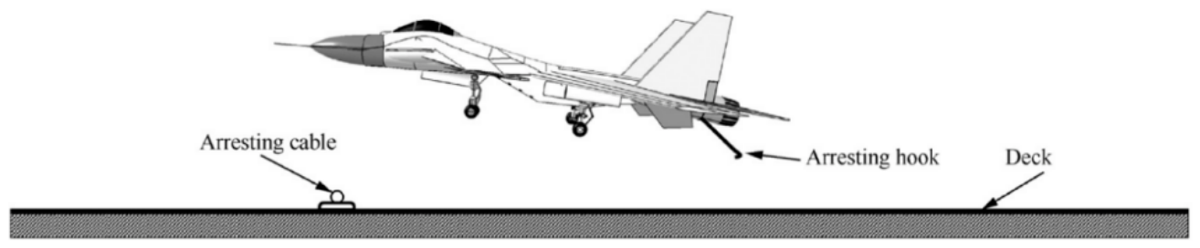
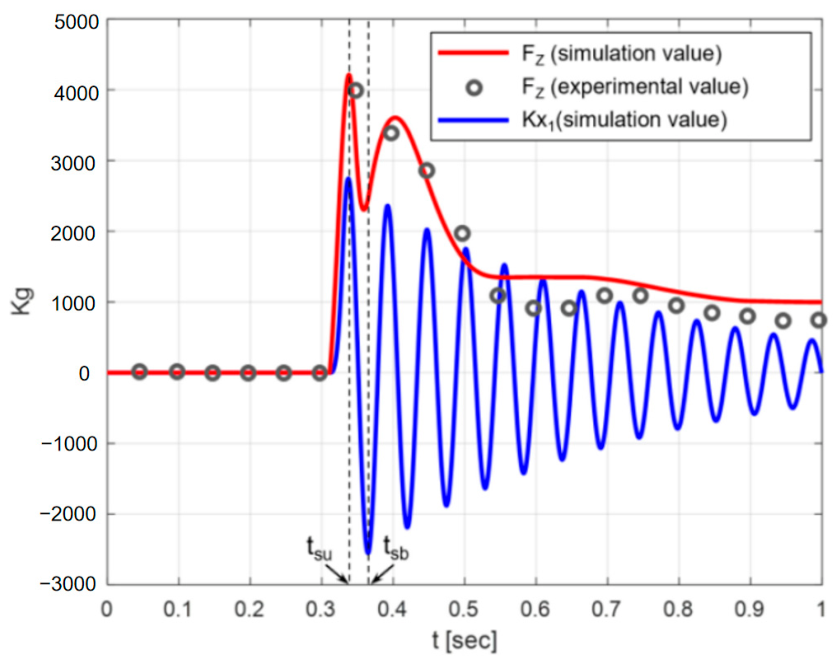
Contact impact loads occur under conditions including landing, carrier landing, ground or deck collision, catapult launch, and local component contact events. During aircraft landing, main-wheel touchdown produces vertical impact, wheel spin-up loads, and elastic rebound loads, which couple the heave, pitch, roll, and local strut responses of tires, shock absorbers, struts, and the overall airframe [16]. In the process of arrested carrier landing, tailhook deck impact, hook bounce, arresting-cable engagement, cable tension accumulation, and rapid aircraft deceleration generate strongly coupled longitudinal, vertical, pitch, and yaw impact loads [17,18]. These load sources possess a unified characteristic: local contact states change within an extremely short period, which easily excites high-frequency transient responses at structural joints, supporting structures, and equipment installation interfaces. Accordingly, contact impact is not confined to the normal contact direction. Vertical touchdown can induce longitudinal drag via tire friction and wheel spin-up, and these loads can be converted into pitch and roll responses through the geometric characteristics of landing gear structures [19]. Similarly, tailhook engagement triggers vertical hook impact, longitudinal arresting deceleration, pitching moments, and yaw disturbances. The characterization of contact impact loads should therefore cover peak acceleration, contact force, load duration, shock response spectrum (SRS), and synchronous correlation among multiple directions. The arresting hook and cable engagement configuration is illustrated in Figure 1. The corresponding vertical and horizontal landing gear force histories are shown in Figure 2.
Pyrotechnic-shock loads mainly stem from explosive bolts, pyrotechnic cutters, separation bolts, and unlocking and release mechanisms, and are characterized by instantaneous action, high amplitude, and broad frequency bandwidth [5,6,20]. Pyrotechnic shock generally manifests as short-duration, high-frequency, and high-acceleration structural shock waves. These shock waves propagate along connecting structures and outer shells and may cause damage to relays, solder joints, electronic components, optical payloads, and precision mechanical structures [21,22]. Different from low-frequency mechanical vibration, pyrotechnic-shock propagation is highly sensitive to local structural impedance, connection interfaces, material damping, and sensor installation distance; its spatial attenuation degree and directional components vary with structural propagation paths. For this reason, the propagation, attenuation, and directional transformation of pyrotechnic shock should be evaluated by combining time-domain waveforms, SRS data, local interface transmissibility, and multipoint synchronous measurement results. Numerical analyses of ridge-cut explosive bolts further illustrate the separation mechanism and local structural response associated with pyrotechnic actuation [23].
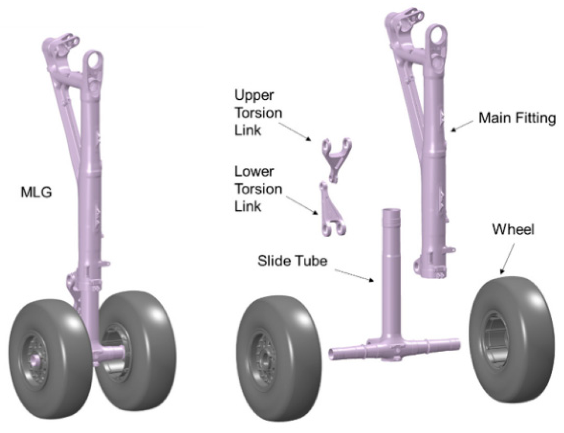
Mechanism-induced shock loads result from typical events, including door opening and closing, landing-gear extension and retraction with lock engagement, positioning of folding wings and deployable surfaces, limit-stop impact, and backlash elimination. During landing-gear extension and retraction, hydraulic actuation, door movement, locking, and limiting processes produce local shock inputs with multidirectional forces and moments near the landing-gear bay, which further excite mid-to-high frequency multiaxial transient responses in the bay structure and adjacent equipment interfaces [24]. For folding wings and deployable aerodynamic surfaces, rapid rotational motion after unlocking, together with subsequent limit-stop impact and lock engagement, also produces significant local shock loads. Such mechanical shocks integrate local high-frequency impacts and structural vibration behaviors. Their amplitudes are determined by actuation velocity, mechanical backlash, structural damping, locking stiffness, and limit-stop material properties, while their propagation range relies on connection stiffness, local cavity modal characteristics, and equipment boundary conditions. In addition to peak load and SRS indicators, the key characterization parameters include mechanism positioning time, contact force history, hinge and lock-pin loads, as well as triaxial acceleration responses at adjacent installation points. The principal landing-gear structural components associated with these mechanism-induced loads are illustrated in Figure 3.
Separation shock loads emerge during external-store release, internal-weapon deployment, drop-tank jettison, actuator configuration switching, and mission-payload release operations. MIL-HDBK-1763 expands aircraft/store compatibility evaluation to the full life cycle of aircraft-store systems, explicitly covering store-separation characteristics, aerodynamic interference effects, and experimental verification methods [26]. After unlocking and separation procedures, the contact constraints between bodies are replaced by relative motion dominated by aerodynamic interactions, forming an inherently coupled multibody aerodynamic and flight dynamic problem [27]. When external weapons or drop tanks separate from wing or fuselage stations, longitudinal, vertical, and lateral shock forces are generated on the pylons, along with pitch, roll, and yaw moment inputs. Classical store-separation studies have demonstrated that safe-separation assessment generally requires the combination of wind-tunnel tests, CFD analysis, and flight tests, as separation trajectories are highly sensitive to the flow field of the host aircraft, initial store attitude, Mach number, mounting position, and ejection operational conditions [28,29]. In internal weapon bays, high-velocity cavity flow induces boundary-layer separation and shear-layer oscillations, which significantly affect the aerodynamic forces, pitching moments, and initial trajectories of weapons [30]. As a store penetrates the shear layer, adverse pressure gradients may generate nose-up pitching moments and even lead to collisions between the store and the host aircraft [31]. Pyrotechnic release devices and separation bolts are widely adopted in external-tank jettison, weapon deployment, and ejection seat systems [20]. Although pyrotechnic devices deliver a high power-to-weight ratio, fast actuation, and superior reliability, they simultaneously generate high-frequency, high-amplitude pyroshock, which may trigger relay chatter, damage miniature circuit components, or induce abnormal operation of sensitive electronic devices. Accordingly, separation shock loads are defined as multiaxial coupled structural responses originating from aerodynamic interference, actuation inputs, abrupt constraint variations, and local structural impact behaviors.

2.2. Multiaxial Vibration Loads

Multiaxial vibration loads are long-duration dynamic loads with abundant frequency content throughout aircraft service. Different from shock loads, vibration loads usually appear as continuous random excitation, periodic harmonic excitation, or narrowband peaks superimposed on broadband spectra, and are primarily produced by mechanical excitation, aerodynamic excitation, base motion, and acoustic excitation.
Mechanical excitation sources cover rotating and reciprocating components such as engines, rotors, compressors, and propellers. For underwing-mounted engines, rotor imbalance and rotational-velocity harmonics produce periodic dynamic loads at engine mounts, pylons, and wing-spar interfaces, which are then propagated through the wing to the fuselage and cabin structures. Slight imbalance in rotating components first triggers periodic loads at bearings and engine mounts and then delivers them to the airframe through the pylon and nacelle. These disturbances can stimulate fuselage vibration, requiring three-dimensional effects at the engine-airframe interface to be considered [32]. For helicopters, propeller-driven aircraft, and electrically propelled aircraft, blade-passage frequencies, rotor aerodynamic imbalance, transmission-system mesh frequencies, and motor electromagnetic force waves may produce narrowband vibration peaks that match structural modes and result in amplification [33,34]. Mechanically induced vibration therefore shows distinct order-related features and should be analyzed using rotational velocity, harmonic peaks, triaxial mount acceleration, coherence functions, and modal frequencies.
Aerodynamic vibration encompasses gusts and turbulence, boundary-layer turbulence, shock oscillation, transonic buffet, vortex shedding, buzz, and aeroelastic limit-cycle oscillation. Aircraft loads are closely linked to aeroelastic phenomena. Moreover, structural design and dynamic response are notably affected by load variations induced by maneuvers, gusts, and turbulence [35]. 14 CFR Part 25 requires compliance with strength requirements across the entire maneuver envelope. It is specified that unsteady aerodynamic forces, rigid-body motion, and critical structural degrees of freedom should be considered in gust-load analysis [36]. Gusts and atmospheric turbulence are typical external random excitations during regular flight. As an aircraft meets discrete gusts or continuous turbulence, rapid variations in freestream velocity and angle of attack generate unsteady fluctuations in lift, drag, and moment, producing multiaxial load inputs in the vertical, lateral, pitch, roll, and yaw directions [37]. Gusts can stimulate multiple bending and torsional modes of the wing, engine pitch/yaw responses, and whole-aircraft elastic modes; response magnitude relies on gust amplitude, flight velocity, and structural stiffness [37,38]. For high-aspect-ratio flexible wings, enhanced flexibility forms feedback between aerodynamic load distribution and elastic deformation. Consequently, coupled variations are caused in wing-root bending moment, wing-tip displacement, fuselage pitch response, as well as vibration at crew and equipment interfaces [39,40]. Under transonic or high-angle-of-attack conditions, shock/boundary-layer interaction, flow separation, and vortex shedding may further trigger buffet, buzz, and aeroelastic limit-cycle oscillations [41,42]. Aerodynamic vibration loads therefore demonstrate broadband randomness, spatial distribution characteristics, and coupling with structural-deformation feedback, and should be comprehensively described via load spectra, triaxial PSDs, structural strain, modal response, and time–frequency features.
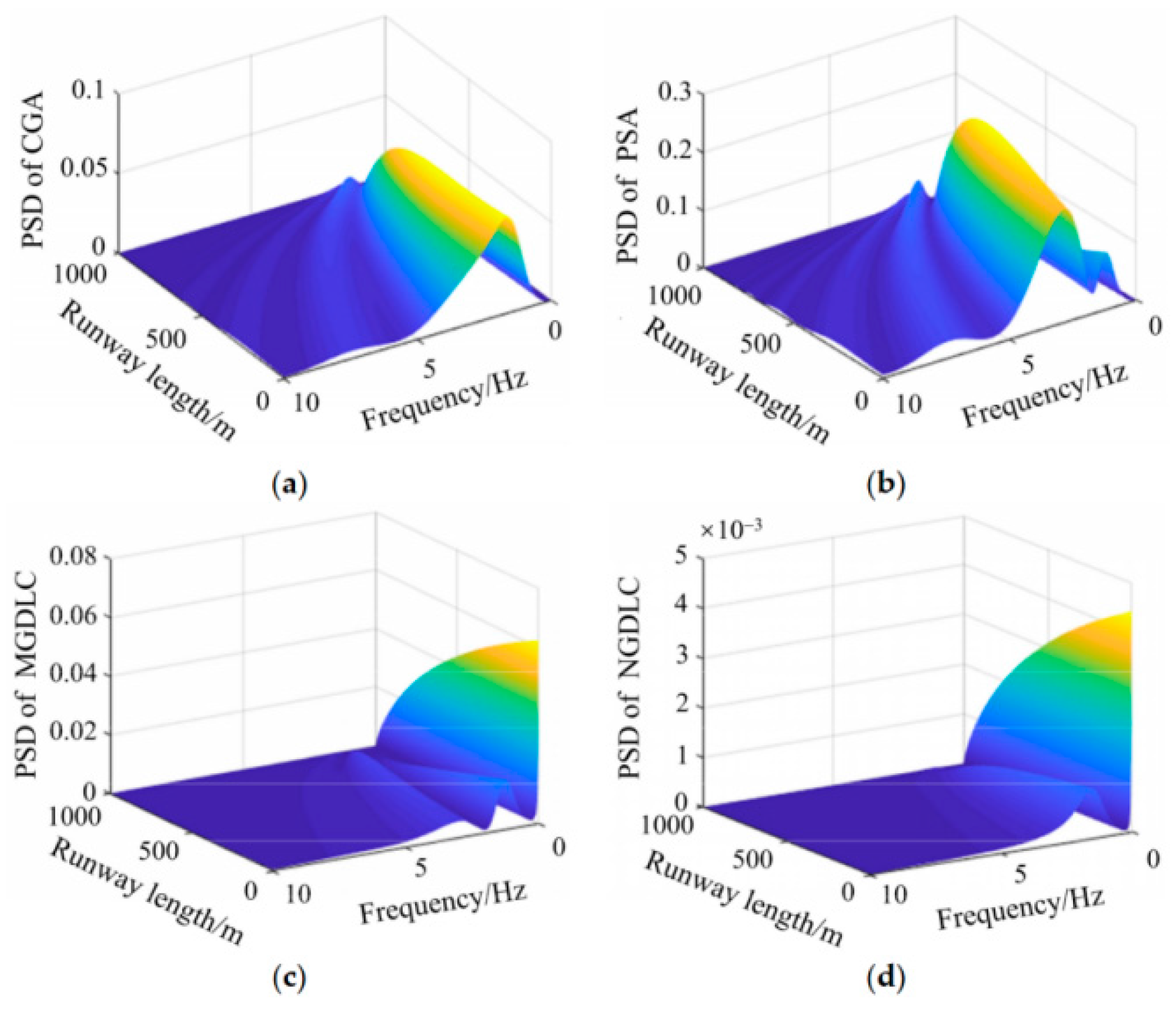
Base-excitation vibration transmits into aircraft structures and onboard equipment via support interfaces, which originates from runway roughness, ship deck motion, chassis vibration, transportation vibration, and ground-test-stand inputs. During acceleration roll, spatial runway irregularities are converted into time-varying contact forces through tires and landing gear systems, further triggering vertical vibration, pitch and roll responses of the airframe. Under three-dimensional runway roughness, vibration magnitudes at the forward fuselage can be considerably higher than those near the center of gravity, while lateral effects generate dynamic load discrepancies between the left and right main landing gears [43]. As the rolling velocity rises continuously, identical runway profiles convert into time-domain excitation with variable frequency components, rendering takeoff-roll vibration velocity-dependent and non-stationary. As a critical transfer path for ground excitation propagating toward the airframe, tire stiffness and shock absorber damping dominate the direction and magnitude of load transfer. Nose landing gear shimmy represents a self-excited coupled vibration behavior that involves lateral tire movement, front-wheel deflection, strut torsion and airframe lateral responses, serving as a typical lateral–torsional multiaxial vibration issue during roll [44]. For carrier-based aircrafts, ship pitch and roll motions alter relative landing velocity, contact attitude and tailhook engagement conditions, thus changing the impact and arresting load characteristics [17,18]. For onboard equipment and mission payloads, base motion occurring during transportation, rollout, launch and ground testing introduces multidirectional accelerations through mounting brackets and platforms, exposing equipment to simultaneous translational and rotational excitation [33,34,45]. The frequency dependent landing vibration responses at representative aircraft locations are shown in Figure 4.
The acoustic-vibration environment mainly arises from launch acoustics, jet noise, high-sound-pressure engine noise, cavity flow noise and boundary-layer pressure fluctuations. NASA-STD-7001B specifies the payload acoustic-vibration environment as the environment induced by high-intensity acoustic noise throughout flight missions, which acts on payloads in the forms of acoustic excitation and structurally transmitted random vibration [47]. Acoustic-vibration loads generally impose spatially distributed pressure fluctuations on aircraft skins, bulkheads and equipment enclosures, which are further converted into local vibration responses via plate-shell structures and connection interfaces. The multiaxial characteristics of such loads are reflected in two aspects. First, the sound pressure field applies spatially correlated distributed loading on structural surfaces, simultaneously activating plate and shell bending, local structural modes and vibration responses at equipment interfaces. Second, the structural transmission of acoustic excitation generates multi-directional acceleration and strain responses. Therefore, this environmental condition can be quantified through sound pressure level, acoustic spectra, structural response PSD, cross-spectral density (CSD) and triaxial acceleration at installation interfaces.

2.3. Shock–Vibration Coupled Environments

The dynamic environment encountered during flight missions seldom consists purely of isolated shock or vibration loads. Instead, it originates from multiple load sources that operate across diverse frequency bands and directions. A shock–vibration coupled environment integrates low-frequency rigid-body motion, mid-frequency structural vibration, high-frequency local shock, and broadband random disturbances. Typical operating scenarios including takeoff, flight maneuvers, and landing all fall within such coupled environments.
During takeoff, aircraft shift from ground-restricted motion to free flight and undergo a highly non-stationary, multisource dynamic environment. A complete takeoff process covers engine acceleration, ground rolling, rotation, liftoff, and landing gear retraction. Shock and vibration loads generated in this stage primarily stem from runway roughness, tire-runway contact, engine rotational frequency and harmonic excitation, jet noise, and load transients associated with liftoff and mechanical retraction. Fast-changing wheel load magnitudes and vanishing ground contact throughout rotation and liftoff induce coupled dynamic responses, covering vertical unloading shock, longitudinal acceleration, pitch attitude variation, and attenuating low-order airframe vibration [46]. For carrier-based aircraft, catapult-assisted takeoff generates intensive longitudinal and vertical coupled shocks driven by catapult traction, instantaneous holdback release, and nose landing gear rebound [48].
In cruising flight and maneuvering states, an aircraft is subjected to combined aerodynamic and propulsion loads, which manifest mainly as broadband vibration responses. Transient load peaks can also emerge during high-g maneuvers, gust encounters, and aeroelastic events. The flight and maneuvering environment thus forms a multiaxial coupled dynamic condition dominated by aerodynamic forces, structural elasticity, maneuver inertial forces, and propulsion system excitation. Rotating mechanical components, such as unbalanced engine rotors and high-bypass fan blades, produce narrowband harmonic vibration throughout flight. These load signals propagate from engine mounts to adjacent structures and onboard devices, forming a composite vibration environment where narrowband harmonic peaks overlay broadband random-vibration backgrounds [49,50].
During landing, aircrafts make runway contact with a certain sink rate and forward velocity. Tire compression and oleo-strut compression initially produce vertical impact loads. Stationary wheels are rapidly accelerated to rolling velocity by runway friction within an extremely short period, generating longitudinal spin-up drag loads, followed by elastic rebound responses from tire and strut structural recovery. Under crosswind conditions, offset touchdown yaw angles, asymmetric main-wheel contact, or uneven runway surfaces further couple vertical impact with lateral friction, longitudinal drag, rolling moment, and yawing moment. Such complex loading may induce nose landing gear buffet, main landing gear shimmy, brake-related vibration, and local fuselage vibration responses [51,52,53]. For arrested carrier landing, ship pitch, roll, heave and deck wind alter the relative touchdown velocity and attitude. The tailhook first impacts and rebounds from the deck surface before engaging the arresting cable. Cable tension is transmitted sequentially through the tailhook, aft fuselage, and primary load-bearing structures to the entire airframe, generating combined dynamic effects including vertical landing impact, rapid longitudinal deceleration, pitching moments, yaw and roll disturbances, and high-frequency local tailhook impact [17,18].

3. Multiaxial Dynamic Load-Transfer Paths and Coupling Mechanisms

3.1. Source–Path–Receiver Framework

The source–path–receiver framework splits complex dynamic environments into three core parts: load source, transmission path, and response receiver. Common load sources cover engines, landing-gear locks, tailhooks, pyrotechnic devices, aerodynamic pressure fields, and base motion. Transmission paths contain support interfaces, fasteners, primary airframe structures, and equipment mounting brackets. Receivers involve sensitive equipment, local structural elements, crew positions, and measurement and control points. Taking the rocket system schematic as an instance, the propulsion system acts as the source, the payload serves as the receiver, and the connecting structure between them forms the path [54].
Transfer Path Analysis (TPA) locates and sorts paths that transmit vibration or acoustic energy from sources to receivers [55]. Traditional TPA builds source–path–response correlations via interface forces and frequency response functions (FRFs), focusing on separating contribution values of physical paths. Operational TPA (OTPA) adopts operational response data to detect dominant transfer paths [56,57], which makes it fit rapid path diagnosis under service conditions. Component-based TPA separately characterizes source components and predicts cross-structural responses. For multiaxial scenarios, TPA cannot only detect the maximum single-direction response; it also should consider multipoint inputs, multidirectional forces and moments, phase differences among paths, and input coherence.
Multidirectional inputs and multiple propagation paths commonly coexist within aircraft structures. A single source can reach a target point via multiple connection points, supports, and structural channels, and each path holds distinct amplitude, phase and frequency response features. Coherent paths can overlap and magnify receiver responses, while incoherent paths add effects via random energy accumulation. The source–path–receiver framework thus offers a unified analytical framework to study load-transfer mechanisms and reconstruct service environments.

3.2. Load Transfer from Interfaces to Structures

Multiaxial dynamic loads initially apply to support interfaces, transfer via connecting structures to the primary structure, and eventually arrive at equipment installation interfaces or sensitive components. Representative support interfaces cover landing-gear-fuselage connections, engine-pylon-wing connections, and tailhook support structures for carrier-based aircraft. Such interfaces transmit both forces and moments simultaneously. For a wing-mounted engine, unbalanced forces first act on bearings and supporting structures before being delivered into the wing via forward and aft pylon attachment points; longitudinal, vertical and lateral load magnitudes at these positions differ from one another [32]. Ground loads acting on landing gear transfer through tires, shock absorbers, side braces, lugs, fuselage frames and beams; vertical impact can simultaneously induce axial compression, bending, drag, and airframe pitch/roll responses [16,19].
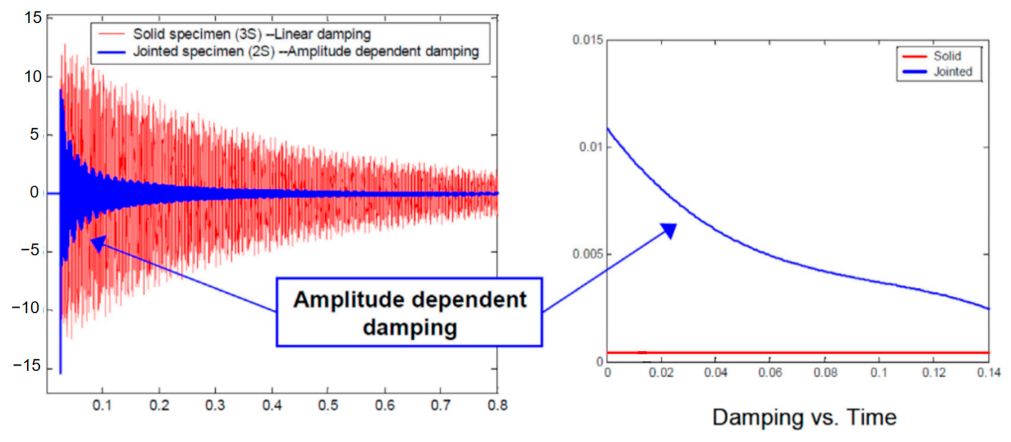
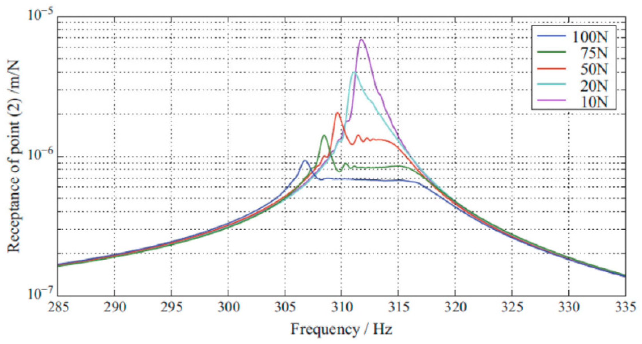
Bolted, riveted and composite joints are extensively adopted in aircraft structures, and these joint regions commonly display preload, assembly clearance and contact nonlinearities. Ibrahim and Pettit illustrated that the dynamic performance of jointed structures is controlled by manufacturing tolerances, contact conditions, preload variation, nonsmooth nonlinearities and uncertainty [58]. Recent summary studies focused on energy dissipation at frictional interfaces further prove that damping levels within bolted joints have tight correlations with interfacial microslip, normal pressure distribution and preload status [59]. Joint interfaces can alter load amplitude, frequency content, and propagation direction under shock loading. For instance, local shock signals transmitted across bolted joints turn into composite responses consisting of low-frequency structural modes and high-frequency local waves [60]. Multiaxial load-transfer analysis thus cannot simplify joints as ideal rigid constraints, and must take joint flexibility, damping, clearance and nonlinear contact behavior into consideration. The amplitude dependent decay behavior of the jointed interface is illustrated in Figure 5. The corresponding excitation level dependence of the bolted structure FRFs is shown in Figure 6.
Beam and shell structures serve as the primary load-bearing media of aircrafts and present unique modal properties during dynamic load transfer. Low-frequency excitations readily trigger global bending, torsion, pitch and roll modes, while high-frequency shocks primarily generate local plate and shell vibration, wave transmission near joints, and resonance of equipment mounting panels [61,62,63]. Once loads enter the primary structure, their allocation across different transmission paths depends on structural geometry, mass distribution, stiffness distribution and boundary restraints. Engine vibration propagates from pylons into wings, then spreads toward cabins and onboard equipment through center wing boxes, frames and stringers [32]. On the contrary, arresting hook loads propagate through the tailhook support structure, aft-fuselage frames, stringers and longitudinal load-bearing components to the entire aircraft [17,18].
Multipath transmission is common within complex aircraft structures. One single load source can propagate to a target point via multiple connection points, supports, and structural channels, and each path carries distinct amplitude, phase and frequency response features. Path contribution ranking conducted via TPA enables researchers to distinguish critical transmission paths, key interfaces and sensitive components, and further guides vibration isolation design, local reinforcement, test control point selection and load environment tailoring [55,56,57].

3.3. Coupling Effects in Multiaxial Load Transmission

Multiaxial load transmission does not represent a linear superposition of individual uniaxial loads; it involves coupled effects across direction, mode, frequency, and nonlinear interfacial behaviors. Directional coupling takes place when excitation applied along a single direction induces structural responses in other directions. During aircraft landing, vertical touchdown impact generates longitudinal drag via tire friction and wheel spin-up. Accordingly, pitch and roll responses can be triggered through landing-gear geometry [16,19]. For carrier-based aircraft tailhook engagement, longitudinal arresting loads couple with vertical hook impact, pitching moments, and yaw disturbances [17,18]. Similarly, radial cyclic loads induced by engine rotor imbalance can be converted through pylon connections into wing bending, torsion, and fuselage lateral vibration [32]. The core concern in multiaxial response analysis lies in how structural geometry and connection boundaries transform local forces into multidirectional forces and moments.
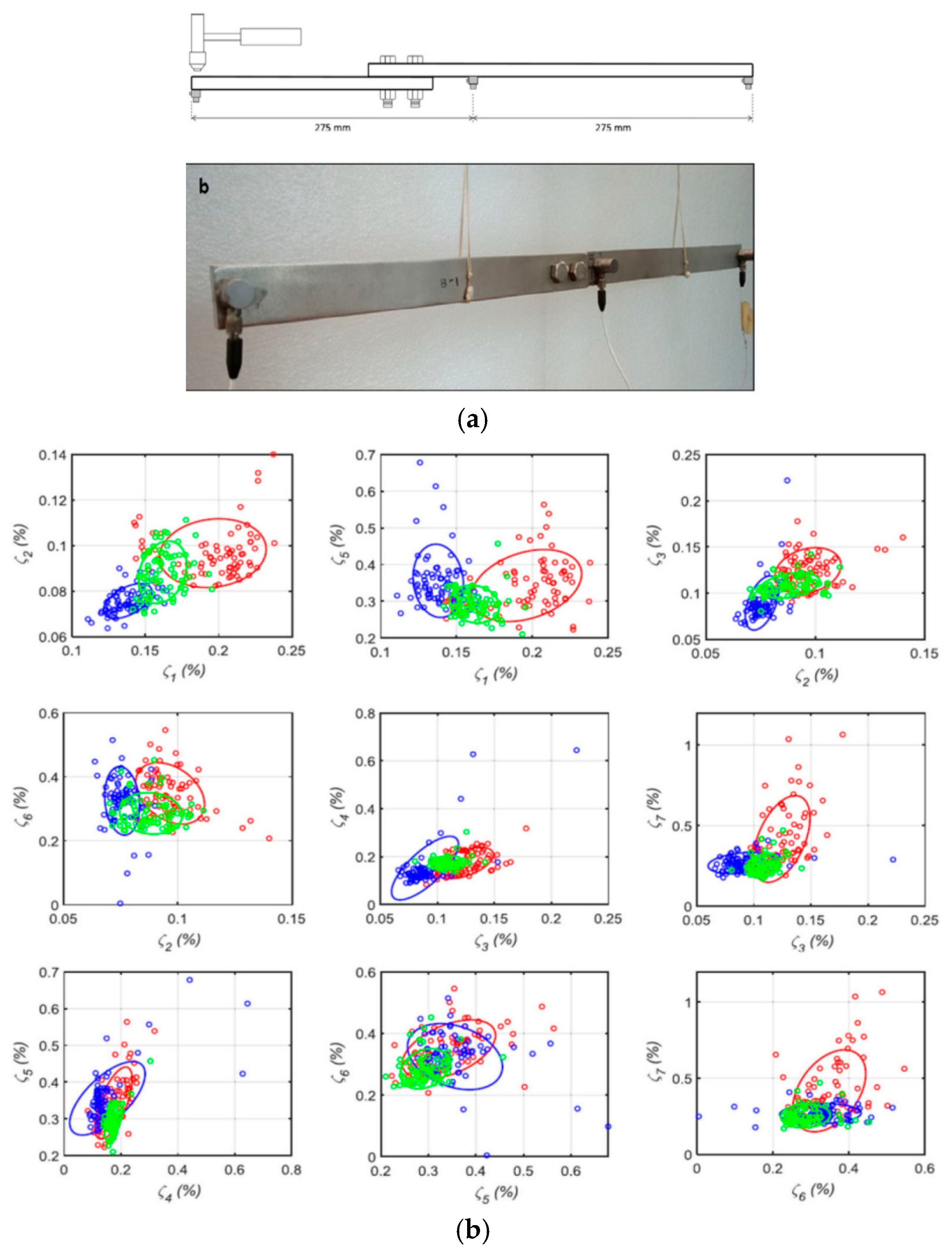
Modal coupling describes the interactive behaviors among bending modes, torsional modes, local modes, and rigid-body motions. For flexible aircraft operating under gusts, flight maneuvers, and transonic conditions, aerodynamic forces, structural elasticity, and flight dynamics interact through feedback loops and simultaneously excite wing bending and torsion, fuselage pitch, and control-surface vibration [35,64]. In assembled structural systems, modal coupling is further governed by joint configurations and boundary conditions. Bolted, riveted, and bonded joints alter local stiffness and damping properties, causing natural frequencies, mode shapes, and damping ratios to vary with preload magnitude, assembly clearance, and excitation amplitude [58,59,60]. Figure 7 presents an experimental case of dynamic uncertainty in a bolted beam, in which modal parameters are extracted via peak picking and other methods to evaluate the influences of surface discrepancy. In ground vibration testing and MIMO modal identification, MIMO excitation can effectively stimulate dense and non-collinear modes of complex structures, thus improving the identification accuracy of multidirectional dynamic characteristics of aircraft [65,66].
Frequency coupling is characterized by the superposition of low-frequency, large-displacement responses and high-frequency, small-amplitude shock or vibration responses. In actual service, aircraft frequently undergo low-frequency maneuver loads, mid-frequency structural vibration, and high-frequency local shock simultaneously. For instance, arrested carrier landing integrates low-frequency longitudinal deceleration and pitch motion with high-frequency local shocks induced by tailhook impact and cable engagement [17,18]. During pyrotechnic separation, low-frequency structural vibration caused by mechanical release accompanies high-frequency acceleration peaks generated by pyrotechnic-shock waves [21,22]. Engine and pump systems also produce rotational-velocity-related narrowband peaks superimposed on broadband random-vibration backgrounds [32]. Such multi-band superposition cannot be fully characterized by individual PSD, SRS, or single-axis sine sweep testing. Accurate characterization requires multiaxial characterization methods that integrate time-domain, frequency-domain, and time–frequency metrics.
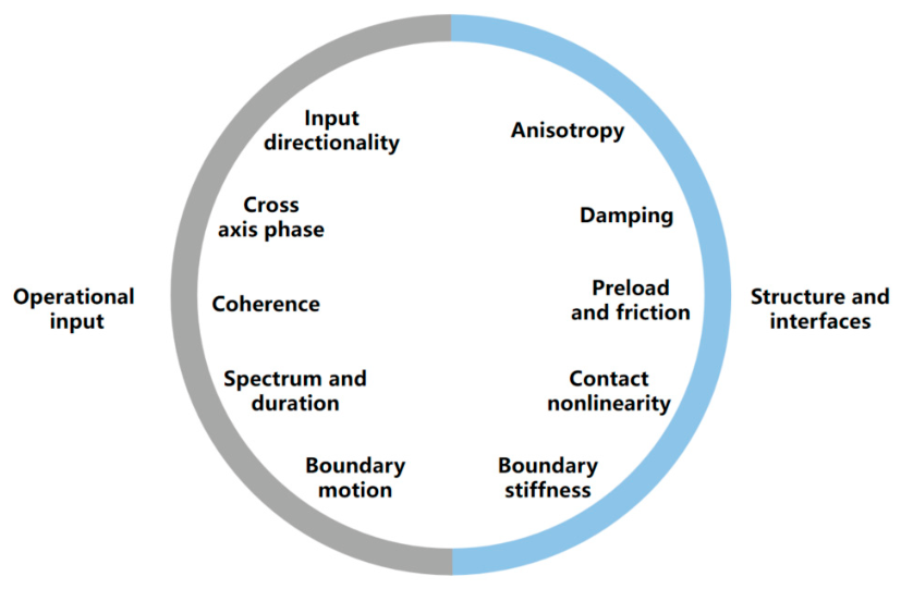
Nonlinear coupling represents the most challenging aspect for modeling and reconstruction in multiaxial load transmission. Aircraft landing-gear shock absorbers exhibit strong nonlinear stiffness and damping, such that landing impact responses vary with sink rate, attitude angle, tire contact condition, and shock-absorber parameters [16,19]. Bolted joints experience microslip and preload relaxation under shock or random-vibration conditions, which alters structural transmissibility characteristics [58,59]. Multiaxial load-transfer models therefore integrate nonlinear connection, contact and damping models where necessary, rather than oversimplifying multiaxial environments as linear time-invariant systems. As summarized in Figure 8, the transmitted multiaxial response is jointly governed by the coherence and directionality of operational inputs and by anisotropy, damping, preload, contact, and other structural-interface properties.

3.4. Multiaxial Load-Environment Reconstruction Methods

Multiaxial environment reconstruction aims to infer load inputs, dominant transmission paths, and equivalent load spectra for experimental validation based on measured or simulated structural responses. This process requires synchronous multisource, multipoint, and multidirectional measurements. Typical measurement indicators include acceleration, angular velocity, strain, force, displacement, and pressure fluctuation. For complex aircraft structures, measurement points are arranged near load sources, support interfaces, primary transmission paths, equipment installation interfaces, and sensitive components to capture the complete propagation chain from input to response. Multi-input multi-output (MIMO) ground vibration tests, full-scale aircraft modal tests, and onboard equipment environmental measurements demonstrate that multipoint measurement and MIMO identification can characterize dense modes, local nonlinearities, and multidirectional response features of complex structures [65,66].
Load identification is central to environment reconstruction. Load inversion can be implemented via inverse dynamics, frequency-response-function (FRF) algorithms, TPA, and OTPA techniques [55,56,57]. FRF-based load identification builds a matrix correlation between response vectors and unknown input forces, and estimates unknown loads through pseudo-inverse solutions, singular-value truncation, Tikhonov regularization, sparse constraints, or Bayesian methods [67,68,69]. Such approaches are applicable for scenarios where direct force sensing is difficult, including engine mounts, gearboxes, external-store pylons, landing-gear attachments, and equipment brackets. For multiaxial environments, load identification aims to evaluate multipoint forces and moments in multiple directions while considering coherence and phase relationships among different inputs.
Multiple-input multiple-output (MIMO) modeling builds a critical connection between service environments and experimental reproduction. Traditional single-axis vibration testing decomposes complex environments into three orthogonal directions for separate application. Despite its operational convenience, this method fails to retain coherence, phase differences, and moment inputs among multidirectional excitations. Smallwood proposed an early multiple-input random-vibration control system suitable for cross-coupled mechanical systems and partially coherent control points [70]. Subsequent investigations on multiaxial hydraulic shakers and multi-exciter random-vibration control further improved MIMO control algorithms, spectral matrix correction, and CSD regulation at control points [71,72]. The multi-exciter testing principle specified in MIL-STD-810 also indicates that multi-directional loading via multiple exciters can better approximate the multiaxial boundary conditions of aircraft service environments [34].

4. Multiaxial Dynamic Response Analysis Methods

The modal model of a multi degree of freedom (MDOF) system is obtained from modal analysis of the FEM model. The governing equation is:
M   x ¨ ( t ) + K   x ( t ) + i   D   x ( t ) = f ( t )
comprising the mass matrix M , the damping matrix D , the stiffness matrix K , the force f ( t ) and the displacements x ( t ) . The solution of the eigenvalue problem gives the eigenfrequencies and eigenmodes, characterizing the dynamic properties of the MDOF structure. Modes are decoupled and the modal superposition approach is used to further deduce the response model, which conveniently provides the relationship between the excitation F and the response X :
X = H ( ω ) F
where the jk-th element of the receptance matrix H ( ω ) is calculated using an assumption of the hysteretic damping:
H j k ( ω ) = r = 1 N ϕ j r ϕ k r ω r 2 ω 2 + i η r ω r 2
where ω r 2 is the r-th natural frequency, η r is the modal damping loss factor for the r-th natural frequency and ϕ j r is the jr-th element of the mass-normalized modal matrix ϕ .
The transfer-function matrices H a s relate the kinematic random excitation S X ¨ ( ω ) to the acceleration responses for model updating. The transfer-function matrices H a s relate the excitation to the stress responses:
S s ( ω ) = H a s * ( ω ) H a s ( ω ) S X ¨ ( ω )
The stresses S s ( ω ) are described in the frequency domain by the auto-spectral and cross-spectral densities of the six independent stress-tensor components in the form of a 6 × 6 matrix:
S s ( ω ) = S x x , x x ( ω ) S x x , y z ( ω ) S y z , x x ( ω ) S y z , y z ( ω )

4.1. Multiaxial Shock Dynamics Modeling for Aircraft

At the modeling scale, multiaxial shock dynamics can be described by three categories of models. The first category includes engineering equivalent models, such as half-sine, trapezoidal, sawtooth, and measured shock-pulse inputs, which apply to test specifications and rapid response estimation [33,73]. The second category covers finite-element and multibody dynamics models for landing-gear drop tests, structural collision events, mechanical lock-up shocks, door extension and retraction, and local stress analysis [74,75]. The third category contains frequency-domain and response-spectrum models for pyrotechnic-shock evaluation and high-frequency-sensitive equipment assessment [76,77,78,79,80,81]. Engineering equivalent models support standardized testing, finite-element and multibody models reveal physical mechanisms, and response-spectrum and frequency-domain models enable shock severity evaluation at the equipment level.
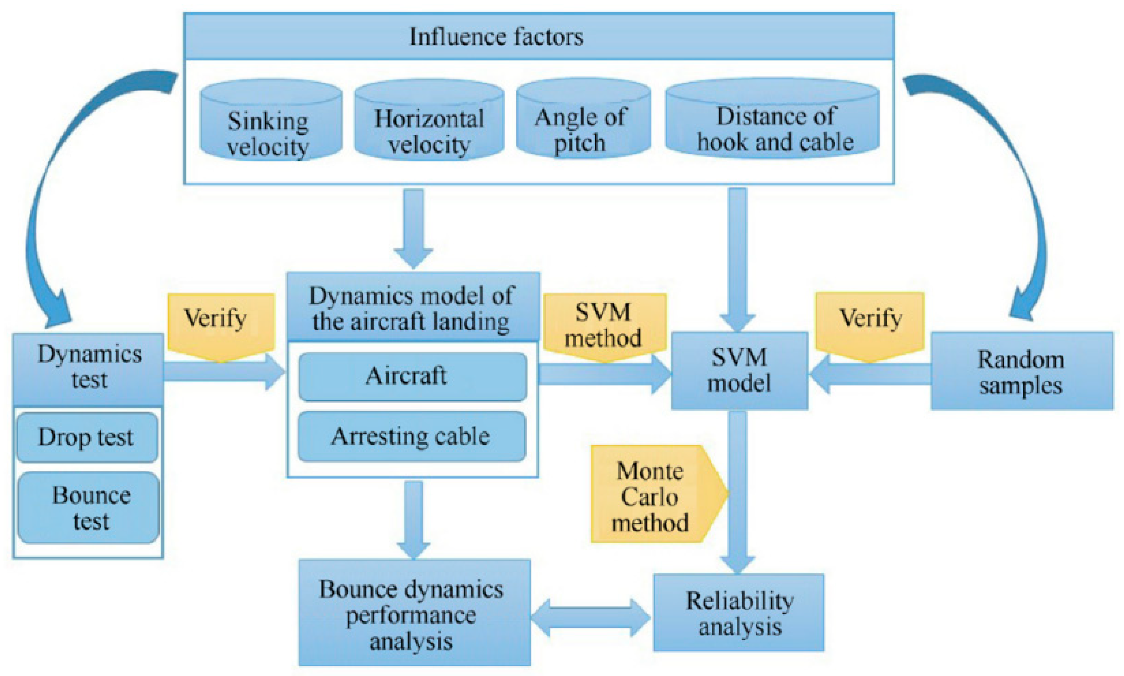
In aircraft landing and ground operation scenarios, landing gear serves as a key path for multiaxial shock input and load transmission. Pecora proposed a numerical simulation method for oleo-pneumatic landing-gear drop shock and proved that landing gear absorbs landing kinetic energy and reduces shock loads transmitted to the airframe [19]. Kang et al. modeled a magnetorheological-damper-equipped landing gear as a two-degree-of-freedom system and assessed its buffering performance through drop tests [74]. Multi-degree-of-freedom (MDOF) drop simulations show that full-aircraft analysis must consider coupling among the fuselage, main landing gear, nose landing gear, pitch and roll attitudes, and the travel of each gear [75]. Liu and Wang incorporated structural flexibility and bearing contact into multibody drop simulations. It is highlighted, that longitudinal axle loads or local contact responses cannot be accurately predicted by rigid-body multibody models alone [25]. As indicated by the above-mentioned studies, multiaxial shock modeling is not restricted to vertical shock. Longitudinal drag, lateral eccentric loading, tire-runway contact, airframe attitude variation, and local flexible connections should also be considered. For carrier arresting applications, the cable engagement reliability calculation process is summarized in Figure 9.
For pyrotechnic and separation shocks, modeling faces inherent challenges including ultra-short duration, broad frequency bandwidth, high peak magnitude, and strong local attenuation. NASA-STD-7003A defines pyrotechnic-shock test criteria for verifying spacecraft, payload, and launch-vehicle hardware [76]. NASA GEVS also adopts the SRS to evaluate the shock environment of spacecraft components [45]. Wang et al. predicted broadband pyrotechnic-shock responses of spacecraft structures using acceleration FRFs and virtual component mode synthesis, and validated that FRFs and component mode synthesis associate shock sources with equipment responses [21]. Battiato et al. presented a parametric model for aerospace pyrotechnic-shock testing to support test facility design and shock environment simulation [77]. Zheng et al. studied multi-excitation SRS reproduction control and provided signal synthesis and control strategies for multipoint, multidirectional shock tests [78]. Thus, rather than relying solely on single-point peak acceleration, modeling of pyrotechnic and separation shocks should integrate local shock sources, connection interface impedance, structural wave propagation, modal responses, and equipment sensitive frequency bands.

4.2. Multiaxial Vibration Dynamics Modeling for Aircraft

The dynamic modeling of multiaxial vibration demands unified descriptions of rigid-body motion, elastic vibration, and unsteady aerodynamic characteristics. Saltari et al. derived rigid-structure coupled dynamic equations for flexible aircraft based on the weak form of unconstrained elastic continua, and constructed a state-space model integrating rigid-body, elastic, and aerodynamic state variables via the finite element method (FEM), doublet-lattice aerodynamics, and rational-function approximation [82]. For high-aspect-ratio flexible wings and aircraft with large deformation behaviors, conventional linear small-perturbation models often fail to achieve accurate response prediction. Wang et al. proposed a nonlinear modal aero-servoelastic framework that projects the governing equations of geometrically nonlinear composite beams into modal coordinates and couples these equations with two-dimensional unsteady aerodynamics, enabling nonlinear dynamic analysis to cooperate with linear aero-servoelastic approaches [83]. Castellani et al. adopted multibody dynamics to simulate aircrafts equipped with high-aspect-ratio wings. The wing structure is discretized into rigid-body segments connected by beam elements to calculate static aeroelasticity, gust responses, and flight loads [84].
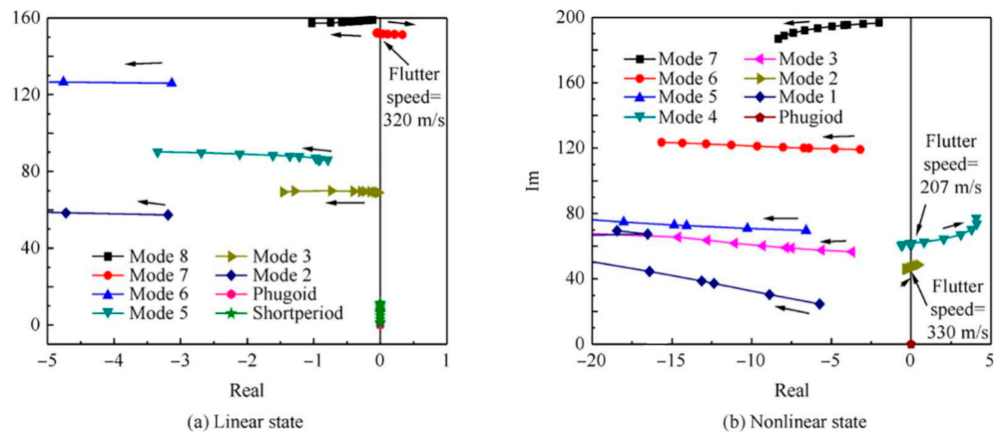
Geometric nonlinearity serves as a core consideration in the multiaxial vibration modeling of flexible aircraft. Wang et al. developed a nonlinear aeroelastic trim and stability analysis method for highly flexible aircraft using co-rotational beam theory. To be specific, co-rotational structural elements are combined with the ONERA nonlinear unsteady aerodynamic model for analyzing dynamic responses and stability under large deformation [85]. Xie et al. established an aeroelastic stability framework for geometrically nonlinear flexible wings by integrating geometrically nonlinear structural FEM with nonplanar vortex-lattice and doublet-lattice methods, and validated the proposed model through wind-tunnel tests [86]. When control systems, actuators, and sensors interact with structural dynamic responses, multiaxial vibration modeling should be extended to aero-servoelastic models. Liu and Xie established nonlinear coupled dynamic equations for flexible aircraft and linearized these equations at nonlinear equilibrium states to acquire state-space models for stability evaluation [87]. This model characterizes the coupling effects among multiaxial aerodynamic loads, structural elastic vibration, and control-system feedback, providing a theoretical basis for investigating gust response, body-freedom flutter, and active load alleviation of flexible aircraft. The coupled dynamic stability-analysis framework for flexible aircraft is illustrated in Figure 10.
For payloads and onboard equipment, multiaxial vibration modeling must fully consider the discrepancies between laboratory test boundary conditions and practical installation boundaries. Remedia et al. proposed a virtual vibration testing method that integrates spacecraft FEM models, shaker dynamic models, and control-system models for pre-test prediction and post-test model updating [88]. Aglietti et al. explored the validation approaches for large-scale spacecraft structural models and virtual vibration testing. The study indicated that test-equipment dynamics, control-system delays, and boundary flexibility influence final test responses and thus should be incorporated into computational models [89]. Multiaxial test data can also improve FEM correlation accuracy, and structural mass, stiffness, and damping matrices can be directly identified via system identification techniques [90]. Therefore, multiaxial vibration modeling for onboard equipment and space payloads should not rely only on fixed-boundary single-axis base excitation; it should use boundary models that better reflect installation interfaces, fixture flexibility, and multipoint input relationships.
In brief, a rational multiaxial vibration model should describe input correlation, modal coupling, connection-boundary nonlinearities, and equipment functional response within a unified framework.

4.3. Response Analysis Methods for Multiaxial Shock Loads

Multiaxial shock response analysis requires rigorous characterization of the shock pulse. In general, standard tests use classical pulses (e.g., half-sine, terminal-peak sawtooth, and trapezoidal pulses). IEC 60068-2-27 employs specified pulse shapes for assessing the ability of test specimens to withstand non-repetitive or repetitive shock [73]. Yan et al. proposed a generalized shock waveform and characterization method, which models pyrotechnic and ballistic shocks as superpositions of multiple decaying harmonic components, with relevant parameters characterizing shock complexity and dominant propagation distance [79]. Shock-pulse characterization should therefore cover not only peak acceleration but also duration, velocity change, dominant frequency components, energy distribution, and multidirectional synchronization.
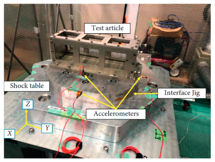
The SRS works by applying input shock signals to a series of single-degree-of-freedom systems with varying natural frequencies and a fixed damping ratio, and records the maximum response of each system to evaluate the frequency-dependent shock sensitivity of equipment. NASA GEVS and NASA-STD-7003A adopt SRS to quantify pyrotechnic-shock environments and formulate corresponding test criteria for spacecraft components [45,76]. Igusa et al. explored an SRS estimation method based on the Goddard standard and pointed out that interface-installed SRS should be evaluated in the early design stage when full-vehicle test data are inaccessible. Adebolu et al. further established a quantitative SRS similarity metric to quantify the matching degree between experimental shock spectra and target spectra [81]. The experimental arrangement used for quantitative SRS similarity assessment is shown in Figure 11.
Multidirectional shock synchronization serves as the core distinction between multiaxial and single-axis shock response analysis. Aircraft shock events commonly generate coupled responses across multiple directions simultaneously. For instance, arrested carrier landing produces coupled vertical shock, longitudinal arresting deceleration, and pitch motion responses. Landing-gear touchdown integrates vertical compression, longitudinal rolling friction, and lateral yaw disturbance. Door or lock impacts may also impose normal shock, tangential frictional shock, and torsional loads to local structures. Sequential single-axis shock testing breaks the temporal correlation of directional peak responses and fails to reproduce modal coupling and damage-accumulation paths. As indicated by studies on multi-excitation SRS reproduction, in multipoint shock testing, it is imperative to construct response signals that satisfy the target SRS using approaches (e.g., random-delay superposition and filtered superposition) [78].
Pyrotechnic shock, lock-up collision, and landing impact can induce severe local stress concentration at fasteners, supporting structures, wheel axles, door hinges, and solder joints, while simultaneously triggering global modal vibration of airframe and equipment mounting structures. Wang et al. predicted broadband pyrotechnic-shock responses using FRF and virtual modal synthesis methods, and verified that FRFs can correlate local shock sources with dynamic responses at remote equipment installation positions [21]. The low-pass filtering algorithm proposed by Yan et al. is also applicable for evaluating shock transmissibility between equipment interfaces and sensitive component interfaces [80].

4.4. Response Analysis Methods for Multiaxial Vibration Loads

Multiaxial vibration response analysis falls into four categories: time-domain analysis, frequency-domain analysis, modal analysis, and response-spectrum or fatigue-spectrum analysis. Time-domain analysis is applicable to transient shocks and landing impacts, as it retains phase relationships among multidirectional inputs, peak synchronization characteristics, and event sequences. This method is thus suitable for the analysis of nonlinear contact, gap impact, friction behavior, and material failure. Landing-gear drop simulation, magnetorheological damper response analysis, and flexible multibody shock modeling represent typical time-domain analysis applications [74,75]. For nonlinear systems, time-domain integration can directly handle nonlinear forces and abrupt boundary variations, though it involves high computational cost and is sensitive to damping, contact stiffness, and time-step selection.
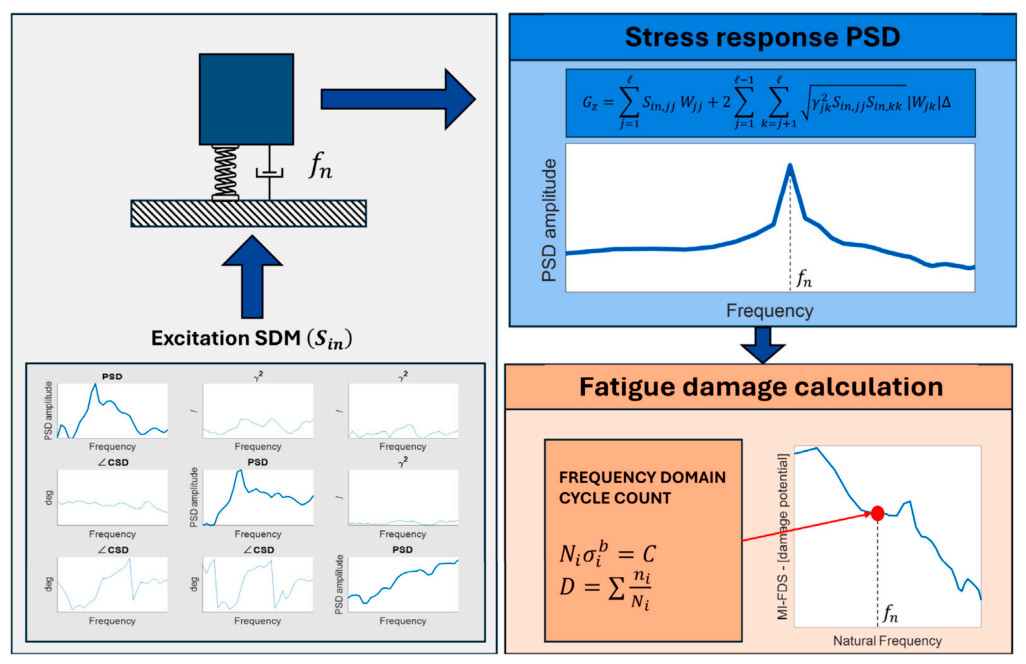
Frequency-domain analysis transforms the input PSD matrix into the response PSD matrix for the calculation of root-mean-square responses, peak estimates, fatigue damage, and interface loads. Existing studies on MIMO random-vibration control verify that both auto-power spectral density and cross-power spectral density act as control targets for multiaxial random testing [91,92]. Triaxial MIMO vibration tests conducted by Roberts and Ewins further prove that this testing method significantly improves the reproduction fidelity of actual three-dimensional operational structural deformations [93]. The multiaxial fatigue damage spectrum (FDS) proposed by Proner and Mucchi extends traditional single-input/single-output FDS theories to MIMO random environments, and emphasizes the importance of phase and coherence in multiaxial fatigue damage evaluation [94]. Frequency-domain analysis therefore requires consideration of not only directional PSDs but also the positive definiteness, coherence, phase, and cross-spectral properties of the spectral matrix. The general workflow used to calculate the multiaxial fatigue damage spectrum is summarized in Figure 12.
Multiaxial excitation can simultaneously trigger coupled bending and torsional modes, particularly for composite structures and high-aspect-ratio wings. To identify such coupled modal characteristics, Ruotolo et al. developed a MIMO curve-fitting technique based on aircraft FRF measurement data [95]. As indicated by the full-scale Hawk T1A MIMO modal dataset reported by Wilson et al., practical aircraft structures exhibit nonlinearity and damage sensitivity. Moreover, the structures can serve as benchmarks for structural health monitoring and system identification [96]. Molina-Viedma et al. acquired full-field operational modal parameters of aircraft composite panels through multiple impact tests, demonstrating that visual measurement combined with multipoint excitation effectively captures local mode shapes [97].
SRS applies to the evaluation of pyrotechnic and transient shocks, while FDS is adopted for random-vibration fatigue damage assessment. Traditional FDS methods are generally developed based on single-input/single-output assumptions, such that they cannot directly characterize phase and coherence relationships among multiaxial inputs. Proner’s multiaxial FDS formulation indicates that practical components essentially belong to MIMO systems, and the phase and coherence of multi-directional inputs are critical for multiaxial random testing [94]. Comparative studies on multiaxial and uniaxial random-vibration fatigue damage further confirm that real service environments are generally multiaxial, and uniaxial testing fails to fully reproduce the actual damage processes observed in laboratories [98]. The principal response analysis methods and their engineering trade offs are compared in Table 2.

4.5. Uncertainty Characterization and Propagation

Aircraft multiaxial response prediction is affected by aleatory uncertainty in operational service loads and material properties, uncertainty in model form and boundary conditions, and measurement/control uncertainty. Uncertainty analysis methods reviewed in this study include Monte Carlo, polynomial-chaos and stochastic-collocation techniques, interval and non-probabilistic approaches, and Bayesian updating. Monte Carlo and polynomial-chaos methods are appropriate when distributions are supported by sufficient data. Interval models are preferable when only bounds are available. Bayesian updating is effective for combining prior models with test measurements.
The principal obstacle is computational cost. Uncertainty propagation may require hundreds or thousands of repeated dynamic analyses. Reduced-order models and surrogate models can reduce this burden while retaining response envelopes. Wang et al. [99] combined structural dimensionality reduction, Sobol sensitivity analysis, Kriging surrogates, optimization, and Bayesian confidence updating to predict high-confidence intervals of aircraft dynamic loads. This type of framework is especially relevant to multiaxial environments because uncertain cross-axis loads, damping, and interface parameters can shift both response extrema and the governing direction.
Uncertainty also enters inverse identification and test design. Shi et al. [100] introduced adaptive probabilistic regularization for element-level damage identification in composite laminates, producing both damage estimates and their probability distributions. Liu et al. [101] evaluated actuator and sensor placement under interval uncertainty using controllability, observability, energy, safety, and distance indicators. These studies indicate that aircraft multiaxial analysis should report confidence or interval bounds for identified loads, damage parameters, control point responses, and acceptance margins.

5. Multiaxial Shock/Vibration Damage Evaluation

5.1. Multiaxial Shock Damage Models

Over the past decade, a damage-modeling framework based on constitutive laws, fracture criteria, and progressive damage models has gradually been established for aircraft metallic and composite structures exposed to multiaxial shock and impact loading.
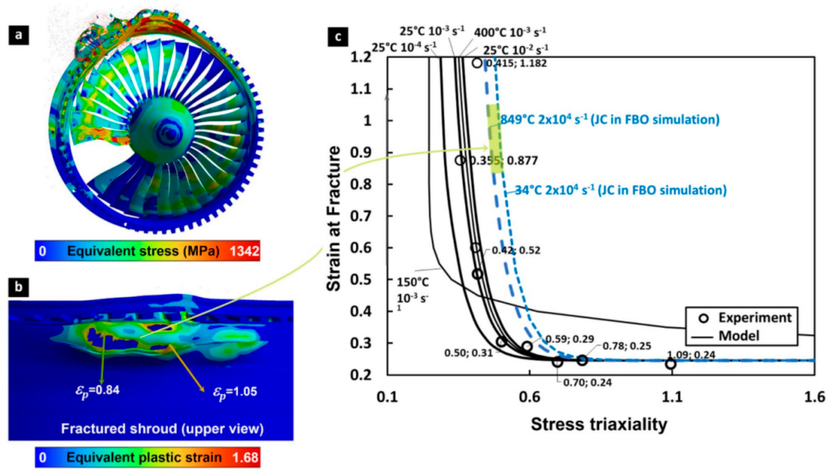
For aluminum and titanium structures, the Johnson–Cook model remains attractive because it combines strain hardening, strain-rate sensitivity, and thermal softening in a compact form that is readily implemented in explicit FEM [102]. Its efficiency makes it suitable for screening high-velocity impact, blade containment, and bird-strike events. The limitation is mechanistic: the classical formulation uses scalar equivalent plastic strain and is weakly sensitive to Lode angle, shear-dominated fracture, and changing stress path [103]. A good match to penetration depth or global energy absorption does not prove correct crack path or fragment generation. Modified Johnson–Cook, triaxiality/Lode-dependent fracture, or coupled damage models are required when those outputs govern certification, and calibration should include multiple stress states rather than a single tensile test [104,105,106]. A representative Johnson Cook fracture analysis for an aero engine fan blade out event is shown in Figure 13.
The Cockcroft–Latham fracture criterion, which relies on maximum principal stress and plastic strain energy density, is capable of characterizing crack initiation and perforation behaviors of ductile metals under tension-dominated loading. It is widely applied for impact failure analysis of aluminum alloy skins, titanium alloy components, and thin-walled energy-absorbing structures, yet it remains sensitive to combined shear-compression loading and varying stress paths [105]. Ductile-fracture models embedded with stress triaxiality and the Lode parameter better adapt to complex fracture problems dominated by coupled tension, shear, bending, and local crushing under multiaxial shock excitation. Such models clarify the transition of damage modes from uniaxial tensile cracking to coupled bending–shear–tension failure during oblique impact, blade separation, and fuselage ground impact events [106].
For composite structures, multiaxial impact damage models focus on anisotropic damage evolution, laminate structural features, and interlaminar interface performance. The three-dimensional Hashin criterion identifies four failure modes, namely fiber tension, fiber compression, matrix tension, and matrix compression, making it suitable for predicting intralaminar damage in CFRP/GFRP laminates, composite skins, and thin-walled structures under low-velocity impact and compression-after-impact conditions. However, accurate characterization of complex shear coupling and delamination growth generally requires coupling with additional interface models [107,108]. The Puck criterion delivers reliable descriptions of matrix cracking and inter-fiber failure, which suits the analysis of matrix-dominated damage, inclined crack propagation, and ply-angle effects under multiaxial stress states. It is commonly utilized for laminates subjected to coupled in-plane tension, compression, shear preload, and impact excitation [109,110]. The LaRC series of failure criteria exhibit superior performance in evaluating fiber compression instability, matrix cracking, and shear nonlinearity, and apply to the progressive damage analysis of aerospace composite structures under complex multiaxial stress states [111]. Cohesive-zone models are primarily adopted to describe the initiation and propagation of interlaminar delamination, and thus apply to interface debonding occurring in low-velocity impact, bird strike, sandwich structure impact, and compression-after-impact scenarios [112,113]. The virtual crack closure technique is more applicable for the propagation analysis of pre-existing cracks and delamination defects, since it allows the calculation of energy-release rates corresponding to different fracture modes [114]. Continuum damage mechanics and progressive damage models can integrate intralaminar damage, interlaminar delamination, stiffness degradation, and residual-strength prediction, making them suitable for full-process analyses from local impact to structural-level load-bearing degradation in composite laminates, sandwich wing leading edges, composite cylindrical shells, as well as helicopter tail structures [115].
Overall, models for metallic structures emphasize high-strain-rate plastic flow, ductile fracture, and perforation, whereas models for composites focus on multiple failure modes, interlaminar delamination, and post-impact residual-performance degradation. In aircraft multiaxial shock scenarios, a single model is rarely sufficient to capture the entire damage process. Accordingly, coupled descriptions that integrate constitutive laws, failure criteria, interface delamination models, and structural-level load-transfer models are typically required [116].

5.2. Multiaxial Vibration Fatigue Damage Models

Multiaxial vibration fatigue introduces an additional reduction problem. A six-component stress process with cross-spectral phase should be converted into cycles and a material damage measure. The main distinction among models is how this reduction is performed. Equivalent stress methods are efficient but suppress crack orientation. Critical-plane methods retain directional failure physics but require a plane search and additional material parameters. FDS-based methods compare environmental severity but depend on the assumed oscillator/material mapping. Sequential uniaxial damage summation is reliable only when cross-axis responses are weakly correlated and the structure remains linear [98].
Frequency-domain equivalent-stress models represent a fundamental set of approaches for multiaxial vibration fatigue damage evaluation, especially for linear structures under stationary random-vibration within the high-cycle fatigue range. Preumont et al. extended classical random fatigue theory to multiaxial stress conditions by converting multiaxial stress PSD data into an equivalent uniaxial random process based on the von Mises quadratic yield criterion, which supports damage calculation using conventional uniaxial random fatigue models [117]. This method possesses a clear mathematical formulation and can be conveniently integrated with FEM-based random response analysis workflows. Segalman et al. further developed an efficient algorithm for RMS von Mises stress calculation by correlating the covariance matrix of random stress components with the root-mean-square magnitude of von Mises stress. This approach applies to strength margin evaluation and critical region identification for linear structures under random vibration environments [118].
To address the deficiencies in conventional von Mises-equivalent methods in characterizing crack orientation and non-proportional multiaxial loading, critical-plane models have been adopted for multiaxial random-vibration fatigue analysis. Cristofori et al. extended the critical-plane criterion to the frequency domain by determining critical-plane orientation from the stress tensor PSD matrix and establishing equivalent normal-stress PSD for fatigue life estimation of metallic structures under multiaxial random loading [119]. Compared with equivalent-stress models, critical-plane models exhibit better adaptability for tension–shear coupling effects, coupled bending–torsion vibration, multiaxial stress concentration near notches, and crack orientation prediction. Nevertheless, such models require higher computational resources and rely heavily on material fatigue parameters, critical-plane searching algorithms, and frequency-domain equivalence assumptions. Mršnik et al. conducted theoretical and experimental comparisons among multiple multiaxial vibration fatigue criteria and confirmed that different criteria yield obvious discrepancies in life estimation and crack location prediction. Multiaxial vibration fatigue assessment therefore requires consideration of not only predicted damage magnitude, but also the model capacity for failure location interpretation and underlying damage mechanism explanation [7].
The aircraft service environment typically behaves as a multi-input and multi-output system, where vibration responses in different directions contain inherent phase differences and coherence relations, and multiple inputs can trigger structural modes simultaneously. For this reason, traditional FDSs fail to reflect the coupled damage effects of multiaxial inputs. The multiaxial FDS proposed by Proner and Mucchi incorporates input correlation into the damage-potential evaluation framework, enabling comparison of fatigue severity across different multiaxial random-vibration environments and providing a quantitative basis for developing multiaxial random-vibration test spectra [94]. Compared with conventional FDSs, the multiaxial FDS simultaneously considers PSDs, cross-spectra, and modal-response differences across input directions. Accordingly, it becomes more suitable for test-environment tailoring and damage-equivalence evaluation of aircraft equipment, brackets, cabin structures, airborne electronics, and connectors.
By comparing damage induced by multiaxial random excitation with damage generated by sequential uniaxial excitation, researchers can establish a damage-correction factor or mapping relationship to convert uniaxial test damage results into multiaxial damage estimations [98]. Such frameworks integrate uniaxial vibration tests, structural FEM models, equivalent stress spectra, input correlation properties and broadband spectral features, while adopting correction factors to quantify the influences of coherence, phase differences and frequency-band characteristics on fatigue damage [120]. These models deliver practical engineering benefits by lowering the cost of multiaxial testing and improving the utilization of existing uniaxial vibration test data. Their applicability, however, generally relies on core assumptions including structural linearity, stationary loading, approximately Gaussian responses, and equivalent damage accumulation rules.
The evolution from equivalent von Mises stress to critical-plane methods, multiaxial FDS, and data-driven corrections has increased sensitivity to phase and non-proportional loading [117,118,119,120,121]. However, comparative studies show that predicted equivalent stress, damage, and crack orientation can differ substantially among criteria [7]. The appropriate response is to select the mechanism consistent with the material and observed failure mode and to quantify model-form spread when evidence is insufficient. For airborne electronics, equipment level fatigue assessment also uses shock fatigue boundaries for BGA solder joints, Steinberg based PBGA vibration life estimates, PCB strain based design criteria, solder joint reliability guidance, and IPC qualification methods [122,123,124,125,126,127].

5.3. Composite Post-Impact Residual Strength

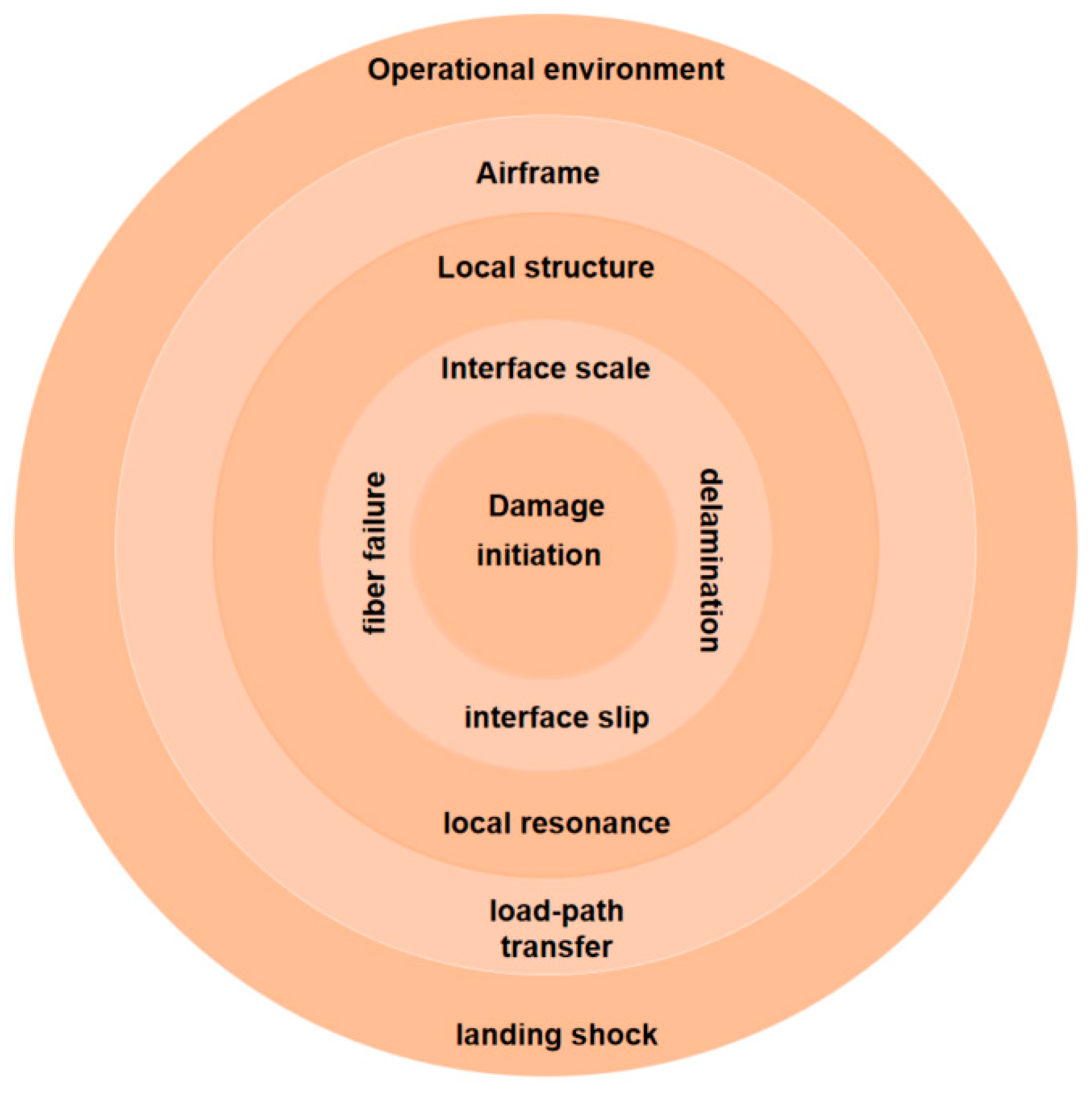
For composite aircraft structures, an engineering objective is to predict the residual load-carrying capacity after impact, including compression-after-impact strength, tensile residual strength, stiffness loss, and the subsequent transition to fatigue-driven damage. Based on these key engineering requirements, this review conducts a comprehensive investigation of the validity of existing damage models. As illustrated in Figure 14, shock–vibration damage evolves across interacting scales, from local matrix cracking, fiber failure, and delamination to component-level stiffness loss and aircraft-level performance degradation.
The computational efficiency of the Hashin criteria makes them attractive for large laminate and structural-component models. However, the standard Hashin formulation does not explicitly resolve the fracture plane of matrix-dominated failure, fiber kinking under compression, or interlaminar delamination. Its prediction of residual strength is therefore strongly controlled by the selected degradation law, element characteristic length, shear interaction assumptions, and the treatment of deleted or severely damaged elements. A Hashin-only model may reproduce the global impact response while still overpredicting post-impact compressive strength if hidden delamination and compression-driven instability are not represented.
Puck and LaRC criteria provide more detailed descriptions of failure mechanisms that are critical to post-impact residual strength. Puck’s inter-fiber failure formulation identifies a physically motivated fracture plane and is particularly useful when inclined matrix cracking and combined transverse–shear loading govern damage development. LaRC formulations offer additional advantages for fiber compression, kink-band formation, matrix cracking, and shear nonlinearity. These features make Puck and LaRC more suitable than simple mode-separated criteria for compression after impact problems, in which matrix cracks, local fiber misalignment, and delamination interact to trigger unstable failure [109,110,111]. Nevertheless, neither criterion constitutes a complete residual-strength model by itself. Both require independently defined evolution laws, fracture energies, unloading rules, and stiffness-degradation schemes. Their improved physical resolution also introduces additional material parameters and calibration requirements. Consequently, their apparent superiority can be lost when the fracture-plane parameters, fiber-misalignment angles, or nonlinear shear properties are poorly characterized.
Cohesive-zone models address the main deficiency in intralaminar criteria by explicitly representing delamination initiation and propagation through traction separation laws. They are effective for low-velocity impact, bird strike, sandwich-panel damage, and compression-after-impact analyses when interlaminar cracking controls stiffness loss and local buckling [112,113]. Their contribution to residual-strength prediction is especially important because delamination often produces limited visible surface damage while substantially reducing compressive stability. The accuracy of a cohesive-zone model depends on interfacial strengths, mode-I and mode-II fracture energies, the mixed-mode interaction law, element size. Pre-inserting cohesive interfaces between all plies can capture multiple delamination fronts but considerably increases model size and may introduce artificial compliance. Conversely, restricting cohesive elements to selected interfaces reduces cost but risks suppressing unanticipated crack paths.
VCCT evaluates delamination propagation from the energy-release rates at an existing crack front. It is well suited to fracture-mechanics-based analysis of known delaminations [114]. It is therefore useful in the residual-strength stage when impact damage has been measured experimentally or mapped from a preceding simulation. Compared with cohesive-zone modeling, VCCT does not require an artificial traction separation process zone. VCCT can provide efficient mixed-mode crack-growth assessment. Its principal limitation is that a crack must be defined in advance. VCCT is more effective for controlled crack-extension studies than for complete blind prediction of impact damage.

5.4. Composite Impact Fatigue Degradation

Post-impact fatigue analysis is more demanding than residual-strength prediction because the model must reproduce both the initial impact damage and its evolution over thousands or millions of load cycles. Impact-generated matrix cracks, fiber fractures, delaminations, and local indentations alter the stiffness field and redistribute the cyclic stresses. The local stress ratio near a damaged region may therefore differ substantially from the nominal load ratio. A credible model must retain the impact damage state, update stiffness and strength during cyclic loading, and predict the transition from stable damage growth to final failure. Experimental and numerical studies confirm that post-impact fatigue durability cannot be assessed reliably from the initial damage area or residual static strength alone [111,116,121].
Hashin models allow the impact-generated intralaminar damage variables to be transferred into a subsequent fatigue analysis. Fatigue degradation can then be introduced through cycle-dependent reductions in residual strength, residual stiffness, or fracture energy. Such formulations are effective when fatigue life is governed by distributed matrix cracking, fiber degradation, or the progressive loss of laminate stiffness. They are also computationally suitable for structural-scale models. However, the original Hashin criteria describe static damage initiation rather than cyclic damage accumulation. Their use in post-impact fatigue therefore requires an additional fatigue evolution law, stress-ratio correction. Its effectiveness consequently depends more on the coupled fatigue-degradation formulation than on the initiation criterion alone [111,116].
Puck and LaRC formulations provide greater physical resolution for matrix-dominated and compression-driven fatigue mechanisms. Puck is suited to cyclic transverse shear stress states around an impact-damaged zone. LaRC criteria offer a more explicit treatment of fiber kinking, initial fiber misalignment, matrix cracking, and nonlinear shear response. Puck and LaRC require fatigue specific residual strength or damage-rate laws, local stress ratio dependence. Higher physical detail increases parameter sensitivity and computational cost.
Impact-induced delamination controls the subsequent degradation of compressive stiffness and stability [121]. A fatigue cohesive formulation extends the monotonic traction separation law by introducing cycle-dependent interface damage, an endurance threshold. The impact analysis can first generate multiple delaminated interfaces, after which cyclic loading drives their progressive expansion and coalescence. The effectiveness of a fatigue cohesive-zone model depends strongly on the interface fatigue law. Parameters are required for the endurance threshold, mode-dependent growth rate. These quantities are generally obtained from mode-I, mode-II, and mixed-mode delamination tests. The predicted fatigue life is also sensitive to penalty stiffness, cohesive-element size, process-zone resolution, and the number of interfaces included in the laminate model. Cohesive elements inserted between all plies can represent interacting delaminations but substantially increase computational cost. Selective interface placement is more efficient but may suppress unexpected delamination paths. Cycle-jump or implicit damage-update schemes are usually required for high-cycle fatigue because direct simulation of every cycle is impractical.
VCCT offers a fracture-mechanics framework for simulating fatigue growth of an existing impact-induced delamination [128]. It evaluates the mode I, mode II, and mode III energy-release rates along a prescribed crack front. These values are then linked to experimentally calibrated fatigue-growth laws, often in Paris-type forms. The method is most effective when the delamination geometry is available from ultrasonic inspection. It is well suited to constant and variable amplitude fatigue analyses of identified delaminations. The principal limitation of VCCT is its dependence on a predefined crack front. The results may also depend on mesh topology, crack-growth increment. The principal shock, impact, residual strength, and fatigue damage models are compared in Table 3.

6. Multiaxial Dynamic Testing Technologies

6.1. Multiaxial Vibration Test Platforms

Multiaxial vibration systems follow three main architectures. Servo-hydraulic platforms provide high force and long stroke at low-to-medium frequencies. They suit large specimens, landing and taxi loads, transport vibration, and rigid-body motion. Their main limits are valve dynamics, oil-column compliance, and actuator interaction at higher frequencies.
Electrodynamic systems provide higher bandwidth and faster control. Single shakers can be arranged as triaxial or multipoint arrays. These systems suit avionics, electronic assemblies, and small aerospace structures. Their limits are shorter stroke, payload constraints, and cross-axis force from fixtures and armatures [33,45,129]. Hybrid hydraulic-electrodynamic systems extend the operating envelope but add interface and control complexity.
MIMO systems use several exciters and response channels to control a spectral-density matrix rather than isolated PSDs. They can reproduce distributed boundary motion, directional coherence, and operational deformation shapes. Their performance depends on the rank and conditioning of the measured frequency-response matrix [91,130,131]. Representative triaxial electrodynamic and six degree of freedom vibration test configurations are shown in Figure 15.
The platform trade off follows the kinematic relation x = a / ( 2 π f ) 2 . A 10 g sinusoidal acceleration requires 24.8 mm of displacement at 10 Hz, but only 0.248 mm at 100 Hz. This two-order reduction explains the long-stroke advantage of hydraulic systems and the high-frequency advantage of electrodynamic systems. Servo-hydraulic tables operate mainly below 100–150 Hz. Electrodynamic arrays can extend to about 2 kHz. Resonant-plate systems reach 103–104 g over roughly 0.1–10 kHz because high-frequency acceleration requires little displacement.
In summary, the selection of multiaxial vibration platforms should match specimen mass, effective frequency range, load type, control objective, and failure modes. For small airborne equipment, triaxial electrodynamic shakers or multi-electrodynamic exciter systems are preferred. Electrohydraulic servo multiaxial platforms are more applicable for large structural specimens under low-frequency and high-displacement working conditions. Six-degree-of-freedom (6-DOF) vibration tables are adopted to apply loads sensitive to spatial rigid-body motion, while multi-exciter MIMO systems serve for structures sensitive to multipoint boundary excitation inputs.

6.2. Multiaxial Shock Test Platforms

Multiaxial shock platforms can apply combined vertical, longitudinal, and lateral shocks, making them capable of simulating multidirectional shock or coupled shock-rotation dynamic environments. These platforms generally comprise multiple shock actuators, guiding structures, damping units, and multichannel control systems, which support synchronous or near-synchronous shock inputs across different directions. Core performance indicators include directional peak acceleration, shock duration, pulse profile, peak time offset, directional coupling error, and test repeatability. The core difficulty of multiaxial shock testing lies not in the expansion of excitation directions, but in the control of peak consistency, phase consistency, and SRS consistency among triaxial responses. Hopkins and Sisemore realized synchronous triaxial shock excitation via eccentric impact on a resonant board, validating the feasibility of multiaxial shock testing based on cross-axis coupling effects. They also pointed out that further investigations are required on triaxial response phase characteristics, tolerance definition criteria, and batch test repeatability [132]. Subsequent assessments of multiaxial resonant-board shock tests and relevant multiaxial SRS studies further prove that multiaxial shock testing requires exclusive test specifications, response evaluation approaches, and tolerance standards that differ from conventional uniaxial shock testing systems [133,134].
Hopkinson bar testing systems are widely adopted to characterize the high-strain-rate multiaxial shock responses of engineering materials. Traditional split Hopkinson pressure bars (SHPBs) are primarily applied to one-dimensional high-strain-rate compression, tension, and torsion tests [135,136]. With the progress of research on material and structural shock behaviors, biaxial, torsion-compression, confining-pressure, and high/low-temperature Hopkinson bar systems have been developed to explore the dynamic mechanical properties of metals, foams, composites, and quasi-brittle materials under complex stress states [2]. To resolve stress wave synchronization issues, Nie et al. [137] proposed an innovative stress wave generation principle and developed an electromagnetic split Hopkinson pressure bar (ESHPB) system, where an LC circuit directly converts electromagnetic energy into incident stress pulses. This method facilitates the flexible generation of both compressive and tensile incident pulses. Compared with conventional pulse generation approaches such as projectile impact and prestressed segment sudden release, electromagnetic energy conversion enables microsecond-scale precise triggering. Nie et al. [138] further established a symmetrically loaded Hopkinson bar system equipped with synchronized electromagnetic stress-pulse generators. This apparatus adopts two identical generators connected to a unified LC discharge circuit to produce dual synchronized stress pulses. Benefiting from the high flexibility of electromagnetic stress-pulse generators, this symmetric shock loading configuration can be conveniently switched between compressive and tensile forms. Stress wave measurements from both incident bars demonstrate that two incident pulses reach the specimen ends nearly simultaneously, with a synchronization error below 3 μs. Hopkins et al. [132] performed analytical and experimental research on triaxial shock testing based on a resonant plate setup. The test component was mounted at the plate center, while the impact point was offset toward one corner. The responses were approximately consistent with the test specifications in two directions, whereas the component input along the third axis was slightly higher. These results demonstrate that simultaneous multiaxial shock testing on a resonant plate is feasible and practical. The symmetric split Hopkinson compression bar configuration discussed above is illustrated in Figure 16.

6.3. Excitation-Signal Generation and Control Strategies

Excitation-signal generation and control strategy can determine whether a multiaxial test can accurately reproduce the target environment. Traditional single-axis tests focus primarily on the acceleration spectrum or shock pulse at a single control point. It is noteworthy that multiaxial tests require simultaneous control of multiple shaker inputs and multiple response points.
Random-vibration control based on a target PSD has become the most widely used method for environmental qualification of aircraft equipment and space payloads. The MIMO random-control method for multiaxial electrohydraulic shakers proposed by Guan et al. converts target PSDs into time-domain random signals and improves the fidelity of target-spectrum reproduction through online control [91,131]. Zhang et al. proposed a matrix power-control algorithm for multichannel spectral control in MIMO random vibration testing [92].
MIMO control serves as a core technology for multiaxial testing. It requires the simultaneous processing of multiple drive and response channels, and it must address strong coupling, ill-conditioning, non-minimum-phase behavior, and frequency-dependent variations in the system FRF matrix. Three-axis vibration tests conducted by Roberts and Ewins demonstrated that MIMO control markedly improves the reproduction of three-dimensional operational deformations of structures under aerodynamic excitation [93]. The enhanced ground-vibration test method proposed by Daborn, Ind, and Ewins further emphasizes that environmental testing should focus on structural response characteristics in realistic aerodynamic environments rather than solely on input spectra [8].
Musella et al. [139] proposed a minimum/maximum driving method for fully automated target definition in MIMO random-control testing. The method is applicable when operational measurements are unavailable or when test specifications provide only PSD targets. By generating the missing CSD, the reference spectral-density matrix can be kept positive semi-definite over the entire test bandwidth, thereby substantially reducing shaker drive power while satisfying the target PSDs.
Table 4 reveals substantial differences in the extent to which current aerospace environmental-test standards cover advanced control strategies. NASA-STD-7001C and GSFC-STD-7000B still rely primarily on independent PSD control applied sequentially along three orthogonal axes. Consequently, these standards do not directly require the reproduction of cross-spectral density, phase, or coherence relationships present in simultaneous multiaxial service environments. MIL-STD-810H Method 525.2 extends the controlled quantity to non-stationary measured time histories, whereas Method 527.2 provides a further framework for multi-exciter testing. Procedure I uses synchronized multichannel time-domain references, while Procedure II uses a complete spectral-density matrix containing both auto-spectral and cross-spectral terms.

6.4. Formulation and Validation of Multiaxial Vibration/Shock Test Conditions

Multiaxial vibration/shock testing primarily aims at translating the aircraft service environment into executable laboratory inputs. On that basis, critical structural responses and damage effects can be reproduced as closely as possible under constrained test conditions. Compared with traditional sequential single-axis testing, multiaxial testing emphasizes synchronous reproduction of multi-directional inputs, multipoint excitation, spatial correlation, phase relationships, and coupled structural responses. MIL-STD-810H Method 527 states that when the service environment exhibits multi-directional, multipoint, or complex spatially correlated characteristics, sequential single-axis testing alone may be insufficient to reproduce the actual structural response; in such cases, multiaxial response measurement and multi shaker loading are required [130]. The method provides both time domain and frequency-domain reference criteria. The former reproduces multipoint time histories, and the latter reproduces PSD and cross spectral matrices. However, MIL STD 810H emphasizes environmental engineering tailoring rather than prescribing fixed test spectra. Therefore, specific test conditions must be comprehensively determined based on mission profiles, measured environmental data, structural response characteristics, damage equivalence objectives, and test equipment capabilities [130].
For multiaxial random-vibration testing, test condition formulation should extend from conventional single-axis PSDs to spectral matrix descriptions that encompass autospectra, cross spectra, phase, as well as coherence. Test spectra derived from measurements must preserve the frequency content and root-mean-square acceleration levels in each input direction. Moreover, the correlations between directions and their effects on critical modes, local stresses, and fatigue damage should be preserved. Angeli et al. proposed a mission synthesis approach based on field measurements, emphasizing that accelerated life test spectra should satisfy frequency content equivalence and fatigue damage equivalence [140]. Proner et al. further investigated the relationship between multiaxial and single-axis random-vibration fatigue damage estimation and proposed an FDS method that incorporates input coherence, phase relationships, and CSD into the damage-potential evaluation framework [94,98]. The above-mentioned studies reveal that multiaxial random-vibration testing should be constrained jointly by spectral matrices, response consistency, and damage equivalence, instead of relying on the independent superposition of PSDs in the three directions.
In test system implementation, multiaxial vibration testing typically relies on multiple exciters, multiple control points, and MIMO control strategies. The European Space Agency’s HYDRA multiaxial vibration facility has been validated using the TEDY dummy satellite model and has been used to reproduce the VEGA ignition transient environment, with test results showing good agreement with coupled load analysis [141]. Comparative SISO and MIMO control tests on automotive exhaust gas recirculation valves with asymmetric mass distributions show that SISO control tends to induce cross-axis response exceedances, whereas MIMO control is better suited to multi directional coupling and coordinated control point responses [142]. Comparisons of response and stress distributions in typical spacecraft structures under sequential single-axis excitation and synchronous three axis excitation reveal that the stress state induced by MDOF excitation differs substantially from that under single-axis excitation, indicating that single-axis testing may underestimate or misidentify local damage risks [143]. As indicated by research on 6 DOF shock and vibration testing, 6 DOF testing should be combined with corresponding 6 DOF dynamic analysis to reconstruct unmeasured stresses and enhance the engineering representativeness of test inputs [144]. Zheng et al. developed a mechanical model of a 6 DOF vibration test system, represented the multiple exciters as equivalent spring damper pairs, assumed the vibration table to be rigid, and analyzed specimen acceleration under 6 DOF base excitation. Their results show that control point placement significantly affects the accuracy of response spectrum reproduction [145].
Recent comparisons quantify the cost of replacing simultaneous loading with sequential tests. In one satellite model, a single-axis test required about 2.5 times the longitudinal base input to match the tri axis acceleration response. The stress state was still different. Matching peak stress required about 2 times the lateral input and 14 times the longitudinal input [143]. Input enveloping can therefore create overtest and undertest in the same article.
For large flexible structures, full-scale aircraft structures, and sophisticated spacecraft structures, multiaxial testing requires integration with MIMO modal identification, FEM updating, and response measurement systems. Ruotolo et al. proposed a MIMO smoothing technique for aircraft data to enhance FRF curve fitting under strongly coupled modal conditions [95]. Wilson et al. developed a MIMO modal test dataset for the Hawk T1A aircraft, proving that modal identification, nonlinear characterization, and damage sensitivity evaluation of full-scale aircraft structures rely on MIMO test data [96]. MIMO vibration testing of inflatable ring structures further reveals that multi actuator loading enables the identification of paired modes with closely spaced natural frequencies and mitigates interference with free free boundary conditions induced by conventional single excitation approaches [146]. Vibration experiments on composite UAV wings similarly demonstrate that modal parameters of lightweight composite structures are highly dependent on structural configuration, material anisotropy, and boundary constraints [147]. Therefore, multiaxial vibration testing serves not only as an environmental reproduction method but also as a vital technical approach for complex structural dynamic parameter identification and model validation.
For shock loading scenarios, test conditions are primarily defined based on the SRS; nevertheless, no one to one correspondence exists between a target SRS and a specific time domain shock waveform. For this reason, multiaxial shock testing cannot merely verify whether the SRS envelope of each individual direction meets specified criteria. It is also necessary to consider measured shock duration, peak acceleration magnitude, energy distribution, attenuation characteristics, frequency band distribution, and inter directional peak time offsets to define synchronization rules and tolerance boundaries for multidirectional shock inputs. The random SRS decomposition method proposed by Hwang et al. adopts probabilistic descriptions of peak acceleration, spectral energy, and phase lag, establishing a systematic framework for spectral decomposition and equivalent reconstruction of complex pyrotechnic and mechanical shock data [148]. In practical test execution, multi shaker SRS reproduction control achieves target shock spectral matrices via coordinated multi shaker loading strategies. Shock on random hybrid control simulates composite dynamic environments where discrete shock events overlay continuous random-vibration backgrounds, offering a feasible technical solution for aircraft coupled shock–vibration testing and multiaxial sine on random fatigue testing [78,149,150].
Aircraft service environments seldom contain pure vibration or pure shock excitations; instead, they represent complex dynamic conditions synthesized by random-vibration, transient shock, structural modal responses, and local damage evolution. Precision optical devices, inertial navigation systems, detectors, electronic components, and payloads are generally installed on multipoint supports or isolation systems. Their dynamic performances depend not only on structural integrity, but also on optical axis stability, pointing accuracy, detector noise, solder joint reliability, and connector contact conditions. Potier et al. conducted random vibration tests on MEMS deformable mirrors for high contrast space imaging and evaluated functional and imaging performance variations before and after vibration excitation [151]. Hasebe et al. performed micro vibration ground tests on the XRISM microcalorimeter and discovered that micro vibrations at specific frequencies interact with cooler harmonics to produce beat frequencies, thus altering the detector noise spectrum [152]. These findings demonstrate that multiaxial vibration and shock testing should assess not only structural safety, but also functional retention, performance degradation, and mission reliability.
In summary, multiaxial vibration and impact testing should be implemented based on measured service environments and mission profiles, with core constraints including spectral matrices, time domain synchronization, phase coherence, control point placement, structural response consistency, and fatigue or impact damage equivalence. The integration of multi shaker loading, MIMO control, multipoint response measurement, SRS reproduction, and shock on random hybrid control establishes a complete technical workflow covering environmental measurement, test condition specification, input reproduction, and structural response evaluation. The representative multiaxial vibration and shock test systems, together with their loading capacities, effective frequency ranges, and typical applications, are summarized in Table 5.

7. Discussion and Prospects

To provide a structured synthesis of the future research needs, the challenges identified throughout Section 3, Section 4, Section 5 and Section 6 are organized according to their associated capability areas. These areas cover multiaxial data acquisition and load reconstruction, multiphysics response modeling, uncertainty quantification, damage and life prognosis, test system integration, and artificial intelligence enabled analysis. This classification links each research gap to the modeling, experimental, computational, and data management capabilities required for its resolution.
Table 6 summarizes the principal research gaps, corresponding future work, enabling capability areas, and potential applications of artificial intelligence. The synthesis highlights the need to transition from separately developed measurement, simulation, damage assessment, and testing methods toward an integrated multiaxial evaluation framework. Within this framework, artificial intelligence can support load reconstruction, model reduction, uncertainty propagation, damage prognosis, adaptive testing, while remaining constrained by physical consistency and experimental validation.

8. Conclusions

For modern combat aircraft and unmanned aerial systems, multiaxial shock and vibration should be assessed at the response, damage, and functional levels. Combat aircraft face tightly coupled loads from high-performance maneuvers, weapon-bay flow, landing impact, and carrier operations, while lightweight composite structures and integrated avionics can redirect loads and turn local disturbances into mission level failures. Unmanned systems are similarly sensitive because flexible airframes and varied launch and recovery methods make their dynamic response highly dependent on mass, stiffness, and control state. Future qualification should therefore combine synchronized service measurements, nonlinear source–path models, coupled damage and residual performance prediction, robust multiaxial testing, and explicit verification of sensor, communication, autonomy, and payload functions. Physics informed models and adaptive testing can support fleet level prognosis, provided that uncertainty bounds and experimental validation are retained.

Author Contributions

Conceptualization, H.D. and Y.Z.; methodology, H.D.; software, H.D.; validation, H.D., Y.Z. and B.Y.; formal analysis, H.D.; investigation, H.D.; resources, B.Y.; data curation, H.D.; writing—original draft preparation, H.D.; writing—review and editing, Y.Z.; visualization, H.D.; supervision, Y.Z.; project administration, Y.M.; funding acquisition, Y.M. All authors have read and agreed to the published version of the manuscript.

Funding

This research received no external funding.

Data Availability Statement

Dataset available on request from the authors.

Conflicts of Interest

The authors declare no conflicts of interest.

References

  1. Habtour, E.; Connon, W.; Pohland, M.F.; Stanton, S.C.; Paulus, M.; Dasgupta, A. Review of response and damage of linear and nonlinear systems under multiaxial vibration. Shock Vib. 2014, 2014, 294271. [Google Scholar] [CrossRef] [Scilit]
  2. Nie, H.; Ma, W.; Wang, K.; Ren, J.; Cao, J.; Dang, W. A review of dynamic multiaxial experimental techniques. Rev. Sci. Instrum. 2020, 91, 111501. [Google Scholar] [CrossRef] [Scilit] [PubMed]
  3. Kumar, J.K.A.; Prabhu, K.S.; Veerendra, A.S.; Shastry, Y.B.S.; Srinivas, G. A comprehensive review of aerodynamic performance evaluation for aircraft wings and engines: Insights into experimental, numerical, and theoretical approaches. Aerosp. Syst. 2025. [Google Scholar] [CrossRef] [Scilit]
  4. Chia, J.W.Y.; Verhagen, W.J.C.; Silva, J.M.; Cole, I.S. A review and outlook of airframe digital twins for structural prognostics and health management in the aviation industry. J. Manuf. Syst. 2024, 77, 398–417. [Google Scholar] [CrossRef] [Scilit]
  5. Lee, J.R.; Chia, C.C.; Kong, C.W. Review of pyroshock wave measurement and simulation for space systems. Measurement 2012, 45, 631–642. [Google Scholar] [CrossRef] [Scilit]
  6. Viale, L.; Fasana, A. Progress in pyroshock simulation for qualification tests: A systematic literature review. Prog. Aerosp. Sci. 2025, 157, 101126. [Google Scholar] [CrossRef] [Scilit]
  7. Mršnik, M.; Slavič, J.; Boltežar, M. Multiaxial vibration fatigue—A theoretical and experimental comparison. Mech. Syst. Signal Process. 2016, 76–77, 409–423. [Google Scholar] [CrossRef] [Scilit]
  8. Daborn, P.M.; Ind, P.R.; Ewins, D.J. Enhanced ground-based vibration testing for aerodynamic environments. Mech. Syst. Signal Process. 2014, 49, 165–180. [Google Scholar] [CrossRef] [Scilit]
  9. Qiao, Y.; Deleo, A.A.; Salviato, M. A study on the multi-axial fatigue failure behavior of notched composite laminates. Compos. Part A Appl. Sci. Manuf. 2019, 127, 105640. [Google Scholar] [CrossRef] [Scilit]
  10. Cheng, Z.-Q.; Tan, W.; Xiong, J.-J. Modelling pre-fatigue, low-velocity impact and post-impact fatigue behaviours of composite helicopter tail structures under multipoint coordinated loading spectrum. Thin-Walled Struct. 2022, 176, 109349. [Google Scholar] [CrossRef] [Scilit]
  11. Kapidžić, Z.; Ansell, H.; Schön, J.; Simonsson, K. Fatigue bearing failure of CFRP composite in biaxially loaded bolted joints at elevated temperature. Compos. Struct. 2015, 127, 298–307. [Google Scholar] [CrossRef] [Scilit]
  12. Ernst, M.; Habtour, E.; Dasgupta, A. Examining Steinberg’s octave rule applicability for electronic systems exposed to multiaxial vibration. IEEE Trans. Compon. Packag. Manuf. Technol. 2016, 6, 561–568. [Google Scholar] [CrossRef] [Scilit]
  13. Yang, X.; Ma, J.; Wen, D.; Yang, J. Crashworthy design and energy absorption mechanisms for helicopter structures: A systematic literature review. Prog. Aerosp. Sci. 2020, 114, 100618. [Google Scholar] [CrossRef] [Scilit]
  14. Zhang, Z.; Peng, Y.; Wei, X.; Li, L.; Wang, Y.; Liu, X. Research on longitudinal dynamics safety boundary of carrier-based aircraft arresting. Aerosp. Sci. Technol. 2022, 130, 107864. [Google Scholar] [CrossRef] [Scilit]
  15. Jackson, K.E. Advances in rotorcraft crashworthiness—Trends leading to improved survivability. J. Am. Helicopter Soc. 2018, 63, 1–25. [Google Scholar] [CrossRef] [Scilit] [PubMed]
  16. Huang, M. Research on loads applied on powered wheels and struts of civil aircraft at touchdown. Proc. Inst. Mech. Eng. Part G J. Aerosp. Eng. 2022, 236, 327–340. [Google Scholar] [CrossRef] [Scilit]
  17. Peng, Y.; Yin, Y.; Xie, P.; Wei, X.; Nie, H. Reliability analysis of arresting hook engaging arresting cable for carrier-based aircraft influenced by multifactors. Chin. J. Aeronaut. 2023, 36, 311–323. [Google Scholar] [CrossRef] [Scilit]
  18. Peng, Y.; Xie, P.; Wei, X.; Nie, H. Dynamics test research of bounce of carrier-based aircraft arresting hook. Appl. Sci. 2020, 10, 9033. [Google Scholar] [CrossRef] [Scilit]
  19. Pecora, R. A rational numerical method for simulation of drop-impact dynamics of oleo-pneumatic landing gear. Appl. Sci. 2021, 11, 4136. [Google Scholar] [CrossRef] [Scilit]
  20. Lee, J.; Han, J.-H. Separation and release devices for aeronautical and astronautical systems: A review. Int. J. Aeronaut. Space Sci. 2025, 26, 131–161. [Google Scholar] [CrossRef] [Scilit]
  21. Wang, X.; Liu, W.; Ding, J.; Sun, Y.; Dang, Y. Pyroshock response prediction of spacecraft structure in wide frequency domain based on acceleration FRF. Aerospace 2022, 9, 54. [Google Scholar] [CrossRef] [Scilit]
  22. Kim, B.S.; Lee, J. Characteristic study of pyroshock propagation in a structure using a pyroshock simulator. J. Vib. Control 2024, 30, 1085–1098. [Google Scholar] [CrossRef] [Scilit]
  23. Lee, J.; Kim, Y.S.; Baek, S.J.; Jeong, H.S. Study of separation mechanism and characteristics of ridge-cut explosive bolts using numerical analysis. Int. J. Aeronaut. Space Sci. 2021, 22, 84–93. [Google Scholar] [CrossRef] [Scilit]
  24. Chen, J.; Xu, Q.; Guo, Y.; Chen, R. Aircraft landing gear retraction/extension system fault diagnosis with 1-D dilated convolutional neural network. Sensors 2022, 22, 1367. [Google Scholar] [CrossRef] [Scilit] [PubMed]
  25. Liu, W.; Wang, Y. Improved multi-body dynamic simulation of landing gear drop test incorporating structural flexibility and bearing contact. Aerospace 2024, 11, 543. [Google Scholar] [CrossRef] [Scilit]
  26. U.S. Department of Defense. MIL-HDBK-1763: Aircraft/Stores Compatibility: Systems Engineering Data Requirements and Test Procedures; Department of Defense: Washington, DC, USA, 1998. [Google Scholar]
  27. Wei, S.; Ai, B. Research progress on multibody aerodynamics. Chin. J. Theor. Appl. Mech. 2022, 54, 1461–1484. [Google Scholar] [CrossRef] [Scilit]
  28. Cenko, A. Store separation lessons learned during the last 30 years. In Proceedings of the 27th Congress of the International Council of the Aeronautical Sciences (ICAS), Nice, France, 9–24 September 2010. [Google Scholar]
  29. Song, W.; Ai, B. Analysis of aircraft-store compatibility for internal weapons separation. Aerosp. Sci. Technol. 2021, 110, 106528. [Google Scholar] [CrossRef] [Scilit]
  30. Lawson, S.J.; Barakos, G.N. Review of numerical simulations for high-speed, turbulent cavity flows. Prog. Aerosp. Sci. 2011, 47, 186–216. [Google Scholar] [CrossRef] [Scilit]
  31. Song, W.; Dong, J.; Lu, W.; Jiang, Z. Trajectory and attitude deviations for internal store separation due to unsteady and quasi-steady test method. Chin. J. Aeronaut. 2022, 35, 74–81. [Google Scholar] [CrossRef] [Scilit]
  32. Zettel, S.F.; Böswald, M.; Dewald, R.D.; Winter, R. Jet engine vibration model for estimating pylon–wing interface loads for realistic structural excitation. CEAS Aeronaut. J. 2025, 17, 1381–1394. [Google Scholar] [CrossRef] [Scilit]
  33. ECSS-E-ST-10-03C Rev.1; Testing. European Cooperation for Space Standardization (ECSS): Noordwijk, The Netherlands, 2022.
  34. MIL-STD-810H; Environmental Engineering Considerations and Laboratory Tests. U.S. Department of Defense: Washington, DC, USA, 2019.
  35. Wright, J.R.; Cooper, J.E. Introduction to Aircraft Aeroelasticity and Loads, 2nd ed.; Wiley: Hoboken, NJ, USA, 2014. [Google Scholar]
  36. Federal Aviation Administration. 14 C.F.R. §25.473, Landing Load Conditions and Assumptions; Electronic Code of Federal Regulations; Federal Aviation Administration: Washington, DC, USA, 2026. [Google Scholar]
  37. Wu, Z.; Cao, Y.; Ismail, M. Gust loads on aircraft. Aeronaut. J. 2019, 123, 1216–1274. [Google Scholar] [CrossRef] [Scilit]
  38. Wan, Z.; Zhang, S.; Wang, X.; Ma, L.; Xu, A.; Wu, Z.; Yang, C. Maneuver load analysis and alleviation technology of flexible aircraft: Review. Acta Aeronaut. ET Astronaut. Sin. 2025, 46, 30279. [Google Scholar] [CrossRef]
  39. Li, Y.; Qin, N. A review of flow control for gust load alleviation. Appl. Sci. 2022, 12, 10537. [Google Scholar] [CrossRef] [Scilit]
  40. Khalil, A.; Fezans, N. Gust load alleviation for flexible aircraft using discrete-time H∞ preview control. Aeronaut. J. 2020, 125, 341–364. [Google Scholar] [CrossRef] [Scilit]
  41. Giannelis, N.F.; Vio, G.A.; Levinski, O. A review of recent developments in the understanding of transonic shock buffet. Prog. Aerosp. Sci. 2017, 92, 39–84. [Google Scholar] [CrossRef] [Scilit]
  42. Gao, C.; Zhang, W. Transonic aeroelasticity: A new perspective from the fluid mode. Prog. Aerosp. Sci. 2020, 113, 100596. [Google Scholar] [CrossRef] [Scilit]
  43. Liu, S.; Zhao, J.; Hou, T.; Ling, J. Mechanism of uneven excitation on the dynamic response of aircraft-runway system. J. Vib. Shock 2025, 44, 198–207. [Google Scholar]
  44. Liu, X.C.; Liu, C.C.; Mou, R.K. Research progress on shimmy dynamics of aircraft landing gear systems. Acta Aeronaut. ET Astronaut. Sin. 2022, 43, 527063. [Google Scholar] [CrossRef]
  45. GSFC-STD-7000B; General Environmental Verification Standard for GSFC Flight Programs and Projects. NASA: Washington, DC, USA; Goddard Space Flight Center: Greenbelt, MD, USA, 2021.
  46. Hou, T.; Liu, S.; Ling, J.; Tian, Y.; Li, P.; Zhang, J. Vibration response law of aircraft taxiing under random roughness excitation. Appl. Sci. 2023, 13, 7386. [Google Scholar] [CrossRef] [Scilit]
  47. NASA-STD-7001B; Payload Vibroacoustic Test Criteria. National Aeronautics and Space Administration (NASA): Washington, DC, USA, 2017.
  48. Zhu, Q.; Lu, P.; Yang, Z.; Ji, X.; Han, Y.; Wang, L. Launch bar dynamics character analysis of carrier-based aircraft catapult launch. Appl. Sci. 2019, 9, 3079. [Google Scholar] [CrossRef] [Scilit]
  49. DO-160G; Environmental Conditions and Test Procedures for Airborne Equipment. RTCA: Washington, DC, USA, 2010.
  50. MIL-STD-810H; Environmental Engineering Considerations and Laboratory Tests, Method, 514.8: Vibration. U.S. Department of Defense: Washington, DC, USA, 2019.
  51. Suresh, P.S.; Sura, N.K.; Shankar, K. Investigation of nonlinear landing gear behavior and dynamic responses on high performance aircraft. Proc. Inst. Mech. Eng. Part G J. Aerosp. Eng. 2019, 233, 5674–5688. [Google Scholar] [CrossRef] [Scilit]
  52. Esmailzadeh, E.; Farzaneh, K.A. Shimmy vibration analysis of aircraft landing gears. J. Vib. Control 1999, 5, 45–56. [Google Scholar] [CrossRef] [Scilit]
  53. Howcroft, C.; Krauskopf, B.; Lowenberg, M.H.; Neild, S.A. Influence of variable side-stay geometry on the shimmy dynamics of an aircraft dual-wheel main landing gear. SIAM J. Appl. Dyn. Syst. 2013, 12, 1181–1209. [Google Scholar] [CrossRef] [Scilit]
  54. Carter, S. A review of using transfer path analysis methods to derive multi-axis vibration environments. In Society for Experimental Mechanics Annual Conference and Exposition; Springer Nature: Cham, Switzerland, 2023; pp. 55–66. [Google Scholar]
  55. Van der Seijs, M.V.; de Klerk, D.; Rixen, D.J. General framework for transfer path analysis: History, theory and classification of techniques. Mech. Syst. Signal Process. 2016, 68–69, 217–244. [Google Scholar] [CrossRef] [Scilit]
  56. De Sitter, G.; Devriendt, C.; Guillaume, P.; Pruyt, E. Operational transfer path analysis. Mech. Syst. Signal Process. 2010, 24, 416–431. [Google Scholar] [CrossRef] [Scilit]
  57. de Klerk, D.; Ossipov, A. Operational transfer path analysis: Theory, guidelines and tire noise application. Mech. Syst. Signal Process. 2010, 24, 1950–1962. [Google Scholar] [CrossRef] [Scilit]
  58. Ibrahim, R.A.; Pettit, C.L. Uncertainties and dynamic problems of bolted joints and other fasteners. J. Sound Vib. 2005, 279, 857–936. [Google Scholar] [CrossRef] [Scilit]
  59. Wang, Y.; Ma, Y.; Hong, J.; Battiato, G.; Firrone, C.M. Experimental studies on the energy dissipation of bolted structures with frictional interfaces: A review. Friction 2024, 12, 1623–1654. [Google Scholar] [CrossRef] [Scilit]
  60. Guo, Y.; Wei, Y.; Yang, Z.; Huang, C.; Wu, X.; Yin, Q. Nonlinearity of interfaces and force transmission of bolted flange joints under impact loading. Int. J. Impact Eng. 2017, 109, 214–223. [Google Scholar] [CrossRef] [Scilit]
  61. Craig, R.R.; Kurdila, A.J. Fundamentals of Structural Dynamics; Wiley: Hoboken, NJ, USA, 2006. [Google Scholar]
  62. Ewins, D.J. Modal Testing: Theory, Practice and Application; Research Studies Press: Hertfordshire, UK, 2000. [Google Scholar]
  63. Maia, N.M.M.; Silva, J.M.M. Theoretical and Experimental Modal Analysis; Research Studies Press: Hertfordshire, UK, 1997. [Google Scholar]
  64. Hodges, D.H.; Pierce, G.A. Introduction to Structural Dynamics and Aeroelasticity; Cambridge University Press: Cambridge, UK, 2011. [Google Scholar]
  65. Zhang, L. A frequency domain MIMO modal identification method with application in the aircraft ground vibration test. SAE Tech. Pap. 1987, 872458. [Google Scholar]
  66. Wilson, J.; Champneys, M.D.; Tipuric, M.; Mills, R.; Wagg, D.J.; Rogers, T.J. Multiple-input, multiple-output modal testing of a Hawk T1A aircraft: A new full-scale dataset for structural health monitoring. arXiv 2024. [Google Scholar] [CrossRef] [Scilit]
  67. Liu, R.; Dobriban, E.; Hou, Z.C.; Qian, K. Dynamic load identification for mechanical systems: A review. Arch. Comput. Methods Eng. 2022, 29, 831–863. [Google Scholar] [CrossRef] [Scilit]
  68. Aucejo, M.; De Smet, O. Identification of dynamic forces using group-sparsity in frequency domain. Mech. Syst. Signal Process. 2016, 70–71, 756–768. [Google Scholar] [CrossRef] [Scilit]
  69. Nelson, P.A.; Yoon, S.H. Estimation of acoustic source strength by inverse methods: Part I, conditioning of the inverse problem. J. Sound Vib. 2000, 233, 639–664. [Google Scholar] [CrossRef] [Scilit]
  70. Smallwood, D.O. A Random Vibration Control System for Testing a Single Test Item with Multiple Inputs; SAE Technical Paper 821482; Aerospace Congress and Exposition: Anaheim, CA, USA, 1982. [Google Scholar]
  71. Zheng, R.; Liu, C.; Feng, G.; Wei, X.; Chen, H. Spectral decoupled correction algorithm for multi-input multi-output random vibration control. J. Vib. Control 2024, 30, 3789–3804. [Google Scholar] [CrossRef] [Scilit]
  72. Ma, Y.; Chen, H.; Zheng, R. Investigation of multi-input multi-output sine on random mixed vibration control. Proc. Inst. Mech. Eng. Part G J. Aerosp. Eng. 2024, 238, 2114–2127. [Google Scholar] [CrossRef] [Scilit]
  73. IEC 60068-2-27; Environmental testing—Part 2-27: Tests—Test Ea and Guidance: Shock. International Electrotechnical Commission (IEC): Geneva, Switzerland, 2008.
  74. Kang, B.-H.; Kim, B.-G.; Choi, S.-B. Aircraft landing gear system with magnetorheological shock strut. J. Intell. Mater. Syst. Struct. 2023, 34, 1471–1485. [Google Scholar] [CrossRef] [Scilit]
  75. Kang, B.-H.; Jo, B.-H.; Kim, B.-G.; Hwang, J.-H.; Choi, S.-B. Linear and nonlinear models for drop simulation of an aircraft landing gear system with MR dampers. Actuators 2023, 12, 287. [Google Scholar] [CrossRef] [Scilit]
  76. NASA-STD-7003A; Pyroshock Test Criteria. National Aeronautics and Space Administration (NASA): Washington, DC, USA, 1999.
  77. Viale, L.; Daga, A.P.; Fasana, A.; Garibaldi, L. On pyroshock tests for aerospace equipment qualification: A comprehensive parametric model for the simulation and the design of pyroshock test facilities. Int. J. Impact Eng. 2023, 180, 104697. [Google Scholar] [CrossRef] [Scilit]
  78. Zheng, R.; Ma, Y.; Wei, X.; Chen, H. Multi-shaker shock response spectra replication control. J. Vib. Control 2022, 29, 3744–3755. [Google Scholar] [CrossRef] [Scilit]
  79. Yan, Y.; Li, Q.M. A General Shock Waveform and Characterisation Method. Mech. Syst. Signal Process. 2020, 136, 106508. [Google Scholar] [CrossRef] [Scilit]
  80. Yan, Y.; Li, Q.M. Low-Pass-Filter-Based Shock Response Spectrum and the Evaluation Method of Transmissibility between equipment and sensitive components interfaces. Mech. Syst. Signal Process. 2019, 117, 97–115. [Google Scholar] [CrossRef] [Scilit]
  81. Adebolu, I.O.; Masui, H.; Cho, M. Quantitative evaluation of SRS similarity for aerospace testing applications. Shock Vib. 2021, 2021, 6655878. [Google Scholar] [CrossRef] [Scilit]
  82. Saltari, F.; Riso, C.; De Matteis, G.; Mastroddi, F. Finite-element-based modeling for flight dynamics and aeroelasticity of flexible aircraft. J. Aircr. 2017, 54, 2350–2366. [Google Scholar] [CrossRef] [Scilit]
  83. Wang, Y.; Wynn, A.; Palacios, R. Nonlinear modal aeroservoelastic analysis framework for flexible aircraft. AIAA J. 2016, 54, 3075–3090. [Google Scholar] [CrossRef] [Scilit]
  84. Castellani, M.; Cooper, J.E.; Lemmens, Y. Flight loads prediction of high aspect ratio wing aircraft using multibody dynamics. Int. J. Aerosp. Eng. 2016, 2016, 4805817. [Google Scholar] [CrossRef] [Scilit]
  85. Wang, W.; Zhu, X.; Zhou, Z.; Duan, J. A method for nonlinear aeroelasticity trim and stability analysis of very flexible aircraft based on co-rotational theory. J. Fluids Struct. 2016, 62, 209–229. [Google Scholar] [CrossRef] [Scilit]
  86. Xie, C.; Liu, Y.; Yang, C.; Cooper, J.E. Geometrically nonlinear aeroelastic stability analysis and wind tunnel test validation of a very flexible wing. Shock Vib. 2016, 2016, 5090719. [Google Scholar] [CrossRef] [Scilit]
  87. Liu, Y.; Xie, C. Aeroservoelastic stability analysis for flexible aircraft based on a nonlinear coupled dynamic model. Chin. J. Aeronaut. 2018, 31, 2185–2198. [Google Scholar] [CrossRef] [Scilit]
  88. Remedia, M.; Aglietti, G.S.; Appolloni, M.; Cozzani, A.; Kiley, A. An enhanced methodology for spacecraft correlation activity using virtual testing tools. J. Sound Vib. 2017, 409, 180–200. [Google Scholar] [CrossRef] [Scilit]
  89. Aglietti, G.S.; Remedia, M.; Appolloni, M.; Kiley, A. On the spacecraft structure model validation and test philosophy. AIAA J. 2019, 57, 2109–2122. [Google Scholar] [CrossRef] [Scilit]
  90. Cerini, C.; Nath, N.; Yotov, V.; Aglietti, G. Spacecraft multi-axis vibration testing: Model correlation, load synthesis and system identification. Aerosp. Sci. Technol. 2026, 177, 112179. [Google Scholar] [CrossRef] [Scilit]
  91. Guan, G.F.; Wang, H.T.; Xiong, W. Multi-input multi-output random vibration control of a multi-axis electro-hydraulic shaking table. J. Vib. Control 2015, 21, 3312–3327. [Google Scholar] [CrossRef] [Scilit]
  92. Cui, X.; Chen, H.; He, X.; Jiang, S. Matrix power control algorithm for multi-input multi-output random vibration test. Chin. J. Aeronaut. 2011, 24, 741–748. [Google Scholar] [CrossRef] [Scilit]
  93. Roberts, C.; Ewins, D. Multi-axis vibration testing of an aerodynamically excited structure. J. Vib. Control 2018, 24, 427–437. [Google Scholar] [CrossRef] [Scilit]
  94. Proner, E.; Mucchi, E. A multi-axial fatigue damage spectrum for the evaluation of the fatigue damage potential of multi-axis random vibration environments. Mech. Syst. Signal Process. 2025, 226, 112362. [Google Scholar] [CrossRef] [Scilit]
  95. Ruotolo, R.; Surace, C.; Crespo, P.; Storer, D. A multiple-input multiple-output smoothing technique: Theory and application to aircraft data. J. Sound Vib. 2001, 247, 453–469. [Google Scholar] [CrossRef] [Scilit]
  96. Wilson, J.; Champneys, M.D.; Tipuric, M.; Mills, R.; Wagg, D.J.; Rogers, T.J. Multiple-input, multiple-output modal testing of a Hawk T1A aircraft: A new full-scale dataset for structural health monitoring. Struct. Health Monit. 2026, 25, 1136–1149. [Google Scholar] [CrossRef] [Scilit]
  97. Molina-Viedma, Á.; López-Alba, E.; Sesé, L.F.; Díaz, F. Full-field operational modal analysis of an aircraft composite panel from the dynamic response in multi-impact test. Sensors 2021, 21, 1602. [Google Scholar] [CrossRef] [Scilit] [PubMed]
  98. Proner, E.; Mucchi, E.; Tovo, R. A relationship between fatigue damage estimation under multi-axis and single-axis random vibration. Mech. Syst. Signal Process. 2024, 215, 111402. [Google Scholar] [CrossRef] [Scilit]
  99. Wang, L.; Fu, Y.; Qiu, Y.; Wang, Y.; Liu, Y. An efficient reduced-order uncertainty quantification framework for high-confidence interval prediction of aircraft dynamic loads. Aerosp. Sci. Technol. 2026, 176, 112065. [Google Scholar] [CrossRef] [Scilit]
  100. Shi, Q.; Xu, C.; Wang, L.; Hu, J.; Chen, W. Research on Adaptive Probabilistic Regularization (APR) method for damage parameter identification of laminated structures. Probabilistic Eng. Mech. 2025, 82, 103852. [Google Scholar] [CrossRef] [Scilit]
  101. Liu, J.; Wang, L.; Hu, J.; Liu, Y. Multi-indicator comprehensive judgement of actuator and sensor optimal placement for uncertain active vibration control systems based on the information entropy and interval closeness theories. Comput. Methods Appl. Mech. Eng. 2026, 450, 118596. [Google Scholar] [CrossRef] [Scilit]
  102. Gara, N.; Ramachandran, V.; Rengaswamy, J. Analytical and FEM analyses of high-speed impact behaviour of Al 2024 alloy. Aerospace 2021, 8, 281. [Google Scholar] [CrossRef] [Scilit]
  103. Beecher, C.; Sepúlveda, H.; Oñate, A.; Habraken, A.M.; Tuninetti, V. Sensitivity analysis of the Johnson–Cook model for Ti-6Al-4V in aeroengine applications. Aerospace 2025, 12, 3. [Google Scholar] [CrossRef] [Scilit]
  104. Tuninetti, V.; Beecher, C.; Arcieri, E.V.; Oñate, A.; García-Herrera, C.; Baragetti, S. Fracture behavior of Ti-6Al-4V in the extreme thermo-mechanical environment of fan blade-out. Sci. Rep. 2026, 16, 4962. [Google Scholar] [CrossRef] [Scilit] [PubMed]
  105. Byun, S.-W.; Joo, Y.-J.; Lee, S.-Y.; Kim, S.-W. Experimental and numerical study on the perforation behavior of an aluminum 6061-T6 cylindrical shell. Materials 2023, 16, 7055. [Google Scholar] [CrossRef] [Scilit] [PubMed]
  106. Wu, S.; Zhou, C.; Shi, Y.; Hu, A.; Xiao, X. Plasticity, ductile fracture and ballistic impact behavior of Ti-6Al-4V alloy. Int. J. Impact Eng. 2023, 174, 104493. [Google Scholar] [CrossRef] [Scilit]
  107. Zhou, J.; Wen, P.; Wang, S. Finite element analysis of a modified progressive damage model for composite laminates under low-velocity impact. Compos. Struct. 2019, 225, 111113. [Google Scholar] [CrossRef] [Scilit]
  108. Shao, J.R.; Liu, N.; Zheng, Z.J. A modified progressive damage model for simulating low-velocity impact of composite laminates. Adv. Mech. Eng. 2022, 14. [Google Scholar] [CrossRef] [Scilit]
  109. Zhang, D.; Zhang, W.; Zhou, J.; Zheng, X.; Wang, J.; Liu, H. Numerical investigation of the low-velocity impact damage resistance and tolerance of composite laminates with preloads. Aerosp. Sci. Technol. 2023, 142, 108650. [Google Scholar] [CrossRef] [Scilit]
  110. Tian, A.; Li, C.; Ma, L.; Chen, X. Nonlinear dynamics of thick hybrid composite laminates subjected to low-velocity impact and various preloading. Materials 2025, 18, 2331. [Google Scholar] [CrossRef] [Scilit] [PubMed]
  111. Cheng, Z.-Q.; Tan, W.; Xiong, J.-J. Progressive damage modelling and fatigue life prediction of plain-weave composite laminates with low-velocity impact damage. Compos. Struct. 2021, 273, 114262. [Google Scholar] [CrossRef] [Scilit]
  112. Arachchige, B.; Ghasemnejad, H.; Yasaee, M. Effect of bird-strike on sandwich composite aircraft wing leading edge. Adv. Eng. Softw. 2020, 148, 102839. [Google Scholar] [CrossRef] [Scilit]
  113. Di Caprio, F.; Sellitto, A.; Saputo, S.; Guida, M.; Riccio, A. A sensitivity analysis of the damage behavior of a leading-edge subject to bird strike. Appl. Sci. 2020, 10, 8187. [Google Scholar] [CrossRef] [Scilit]
  114. Raza, H.; Rodera Garcia, O.; Carpenter, K.; Pärnänen, T.; Jokinen, J.; Kanerva, M.; Bayandor, J. Predictive methods for initiation of delamination and intra-laminar damage in carbon fibre reinforced polymer laminates subject to impact. Aeronaut. J. 2024, 128, 846–874. [Google Scholar] [CrossRef] [Scilit]
  115. Liao, B.; Jia, L.; Zhou, J.; Lei, H.; Gao, R.; Lin, Y.; Fang, D. An explicit–implicit combined model for predicting residual strength of composite cylinders subjected to low velocity impact. Compos. Struct. 2020, 247, 112450. [Google Scholar] [CrossRef] [Scilit]
  116. Harman, A.B.; Webb, L.; Chang, P.; Ibrahim, M.; Wright, C.; Grigoriou, K.; Lua, J.; Hoos, K.; Rapking, D.; Mollenhauer, D.; et al. Post-impact fatigue durability assessment of composite laminates for enhanced aircraft sustainment. AIAA J. 2022, 60, 938–950. [Google Scholar] [CrossRef] [Scilit]
  117. Preumont, A.; Piefort, V. Predicting random high-cycle fatigue life with finite elements. J. Vib. Acoust. 1994, 116, 245–248. [Google Scholar] [CrossRef] [Scilit]
  118. Segalman, D.J.; Fulcher, C.W.G.; Reese, G.M.; Field, R.V. An efficient method for calculating R.M.S. von Mises Stress in a Random Vibration Environment. J. Sound Vib. 2000, 230, 393–410. [Google Scholar] [CrossRef] [Scilit]
  119. Cristofori, A.; Benasciutti, D.; Tovo, R. Reformulation in the frequency domain of a critical plane-based multiaxial fatigue criterion. Int. J. Fatigue 2014, 67, 55–61. [Google Scholar] [CrossRef] [Scilit]
  120. Zhang, Z.; Pan, Y.; Zhou, X.; Li, Q. Multiaxial random vibration life prediction framework via damage correction factor. Int. J. Mech. Sci. 2026, 309, 111047. [Google Scholar] [CrossRef] [Scilit]
  121. Hofman, P.; van der Meer, F.P.; Sluys, L.J. Modeling of Progressive High-Cycle Fatigue in Composite Laminates Accounting for Local Stress Ratios. Compos. Part A Appl. Sci. Manuf. 2024, 183, 108219. [Google Scholar] [CrossRef] [Scilit]
  122. Dang, Y.; Sun, Y.; Hao, Z.; Zhang, Q.; Liu, W.; Yang, C. Shock fatigue damage failure boundary study of BGA solder joints based on shock response spectrum. Int. J. Fatigue 2024, 182, 108214. [Google Scholar] [CrossRef] [Scilit]
  123. An, T.; Qin, F.; Zhou, B.; Chen, P.; Dai, Y.; Li, H.; Tang, T. Vibration lifetime estimation of PBGA solder joints using Steinberg model. Microelectron. Reliab. 2019, 102, 113474. [Google Scholar] [CrossRef] [Scilit]
  124. Steinberg, D.S. Vibration Analysis for Electronic Equipment, 3rd ed.; Wiley: Hoboken, NJ, USA, 2000. [Google Scholar]
  125. Park, T.-Y.; Oh, H.-U. New PCB strain-based structural design methodology for reliable and rapid evaluation of spaceborne electronics under random vibration. Int. J. Fatigue 2021, 146, 106147. [Google Scholar] [CrossRef] [Scilit]
  126. Jiang, N.; Zhang, L.; Liu, Z.-Q.; Sun, L.; Long, W.-M.; He, P.; Xiong, M.-Y.; Zhao, M. Reliability issues of lead-free solder joints in electronic devices. Sci. Technol. Adv. Mater. 2019, 20, 876–901. [Google Scholar] [CrossRef] [Scilit] [PubMed]
  127. IPC-9701A; Performance Test Methods and Qualification Requirements for Surface Mount Solder Attachments. IPC: Bonn, Germany, 2006.
  128. Krueger, R.; Deobald, L.; Gu, H. A benchmark example for delamination growth predictions based on the Single Leg Bending specimen under fatigue loading. Adv. Model. Simul. Eng. Sci. 2020, 7, 11. [Google Scholar] [CrossRef] [Scilit]
  129. IEC 60068-2-6; Environmental Testing—Part 2–6: Tests—Test Fc: Vibration (Sinusoidal). International Electrotechnical Commission (IEC): Geneva, Switzerland, 2007.
  130. MIL-STD-810H; Environmental Engineering Considerations and Laboratory Tests, Methods 514.8, 516.8, and 527. U.S. Department of Defense: Washington, DC, USA, 2019.
  131. Guan, G.; Wang, H.; Xiong, W. Random vibration control of a hydraulic shaking table. J. Vib. Control 2014, 20, 204–217. [Google Scholar] [CrossRef] [Scilit]
  132. Hopkins, R.N.; Sisemore, C.L. Design of a Resonant Plate Shock Test for Simultaneous Multi-Axis Excitation (SAND2019-0777C); Sandia National Laboratories: Albuquerque, Mexico, 2019. [Google Scholar]
  133. Sisemore, C.; Babuska, V.; Flores, R.-X. Multi-Axis Resonant Plate Shock Testing Evaluation and Test Specification Development (SAND2020-9393); Sandia National Laboratories: Albuquerque, Mexico, 2020. [Google Scholar] [CrossRef] [Scilit]
  134. Larsen, W.; Blough, J.R.; DeClerck, J.; Van Karsen, C.; Soine, D.; Jones, R.J. Understanding multi-axis SRS testing results. In Sensors and Instrumentation, Aircraft/Aerospace, Energy Harvesting & Dynamic Environments Testing; Springer: Berlin/Heidelberg, Germany, 2020; Volume 7, pp. 377–385. [Google Scholar] [CrossRef] [Scilit]
  135. Gray, G.T. Classic split-hopkinson pressure bar testing. In ASM Handbook: Mechanical Testing and Evaluation; ASM Digital Library: Materials Park, OH, USA, 2000. [Google Scholar]
  136. Chen, W.; Song, B. Split Hopkinson Bar: Design, Testing and Applications; Springer: Berlin/Heidelberg, Germany, 2011. [Google Scholar]
  137. Nie, H.; Suo, T.; Wu, B.; Li, Y.; Zhao, H. A versatile split Hopkinson pressure bar using electromagnetic loading. Int. J. Impact Eng. 2018, 116, 94–104. [Google Scholar] [CrossRef] [Scilit]
  138. Nie, H.; Suo, T.; Shi, X.; Liu, H.; Li, Y.; Zhao, H. Symmetric split Hopkinson compression and tension tests using synchronized electromagnetic stress pulse generators. Int. J. Impact Eng. 2018, 122, 73–82. [Google Scholar] [CrossRef] [Scilit]
  139. Musella, U.; D’Elia, G.; Carrella, A.; Peeters, B.; Mucchi, E.; Marulo, F.; Guillaume, P. A minimum drives automatic target definition procedure for multi-axis random control testing. Mech. Syst. Signal Process. 2018, 107, 452–468. [Google Scholar] [CrossRef] [Scilit]
  140. Angeli, A.; Cornelis, B.; Troncossi, M. Synthesis of sine-on-random vibration profiles for accelerated life tests based on fatigue damage spectrum equivalence. Mech. Syst. Signal Process. 2018, 103, 340–351. [Google Scholar] [CrossRef] [Scilit]
  141. Appolloni, M.; Fransen, S.; Fischer, H.; Remedia, M. Transient multi-DOF vibration testing: Analytical and experimental data. J. IEST 2020, 63, 75–90. [Google Scholar] [CrossRef] [Scilit]
  142. D’Elia, G.; Mucchi, E.; Dalpiaz, G. Single axis random vibration control testing: Experimental assessment of SISO and MIMO control strategies. In Proceedings of the IMAC XXXVIII: A Conference and Exposition on Structural Dynamics, Houston, TX, USA, 10–13 February 2020; Society for Experimental Mechanics: Bethel, CT, USA, 2021. [Google Scholar]
  143. Nath, N.; Aglietti, G.S. Quantification of the effect of simultaneous tri-axis over sequential single-axis vibration testing. AIAA J. 2023, 61, 890–906. [Google Scholar] [CrossRef] [Scilit]
  144. Owens, B.C.; Tipton, D.G.; McDowell, M.D. 6 Degree of Freedom Shock and Vibration: Testing and Analysis (SAND2016-1583C); Sandia National Laboratories: Albuquerque, Mexico, 2016. [Google Scholar]
  145. Zheng, R.; Chen, H.; Angeli, A.; Vandepitte, D. A simplified modelling and analysis of six degree of freedom random vibration test. Mech. Syst. Signal Process. 2021, 150, 107304. [Google Scholar] [CrossRef] [Scilit]
  146. Ruggiero, E.J.; Park, G.; Inman, D.J. Multi-input multi-output vibration testing of an inflatable torus. Mech. Syst. Signal Process. 2004, 18, 1187–1201. [Google Scholar] [CrossRef] [Scilit]
  147. Simsiriwong, J.; Sullivan, R.W. Experimental vibration analysis of a composite UAV wing. Mech. Adv. Mater. Struct. 2012, 19, 196–206. [Google Scholar] [CrossRef] [Scilit]
  148. Hwang, J.H.; Duran, A.V. Stochastic shock response spectrum decomposition method based on probabilistic definitions of temporal peak acceleration, spectral energy, and phase lag distributions of mechanical impact pyrotechnic shock test data. Mech. Syst. Signal Process. 2016, 76–77, 424–440. [Google Scholar] [CrossRef] [Scilit]
  149. Zheng, R.; Ren, S.; Chen, G.; Chen, H. Multi-shaker half sine shock on random mixed vibration control. J. Sound Vib. 2021, 512, 116372. [Google Scholar] [CrossRef] [Scilit]
  150. Zheng, R.; Chen, H.; Vandepitte, D.; Gallas, S.; Zhang, B. Generation of sine on random vibrations for multi-axial fatigue tests. Mech. Syst. Signal Process. 2019, 126, 649–661. [Google Scholar] [CrossRef] [Scilit]
  151. Potier, A.; Mejia Prada, C.; Ruane, G.; Tang, H.; Baxter, W.; Liu, D.; Riggs, A.J.E.; Poon, P.K.; Bendek, E.; Siegler, N.; et al. Random vibration testing of microelectromechanical deformable mirrors for space-based high-contrast imaging. J. Astron. Telesc. Instrum. Syst. 2023, 9, 029001. [Google Scholar] [CrossRef] [Scilit]
  152. Hasebe, T.; Imamura, R.; Tsujimoto, M.; Awaki, H.; Chiao, M.P.; Fujimoto, R.; Hartz, L.S.; Kilbourne, C.A.; Sneiderman, G.A.; Takei, Y.; et al. Ground test results of the micro-vibration interference for the X-ray microcalorimeter onboard XRISM. arXiv 2023. [Google Scholar] [CrossRef] [Scilit]
Figure 1. Schematic diagram of an arresting hook engaging an arresting cable. Reproduced from Peng [17] under the CC BY-NC-ND 4.0.
Aerospace 13 00722 g001
Figure 2. Time history of vertical and horizontal forces. Reproduced from Pecora [19] under the CC BY 4.0 license.
Aerospace 13 00722 g002
Figure 3. Schematic of landing-gear structural components. Reproduced from Liu [25] under the CC BY 4.0 license.
Aerospace 13 00722 g003
Figure 4. PSD distribution of vibration response during landing: (a) PSD distribution of CGA; (b) PSD distribution of PSA; (c) PSD distribution of MGDLC; (d) PSD distribution of NGDLC. Reproduced from Hou [46] under the CC BY 4.0 license.
Aerospace 13 00722 g004
Figure 5. Effect of jointed-interface damping on the decay rate. Reproduced from Wang [59] under the CC BY 4.0 license.
Aerospace 13 00722 g005
Figure 6. FRFs of the bolted structure under different excitation levels. Reproduced from Wang [59] under the CC BY 4.0 license.
Aerospace 13 00722 g006
Figure 7. Hammer testing of double-bolted joined beams with free boundaries: (a) test setup; (b) variability in damping ratios for 7 N·m (red), 15 N·m (blue), and 23 N·m (green) based on modal parameter identification. Reproduced from Wang [59] under the CC BY 4.0 license.
Aerospace 13 00722 g007
Figure 8. Operational and structural factors governing multiaxial load transmission.
Aerospace 13 00722 g008
Figure 9. Calculation process for cable-engagement reliability. Reproduced from Peng [17] under the CC BY-NC-ND 4.0 license.
Aerospace 13 00722 g009
Figure 10. Coupled dynamic stability analysis. Reproduced from Liu [87] under the CC BY-NC-ND 4.0 license.
Aerospace 13 00722 g010
Figure 11. Experimental setup showing the test article and accelerometers. Reproduced from Adebolu [81] under the CC BY 4.0 license.
Aerospace 13 00722 g011
Figure 12. General workflow for calculating the MI-FDS. Reproduced from Proner [94] under the CC BY-NC-ND 4.0 license.
Aerospace 13 00722 g012
Figure 13. Ring fracture analysis under extreme FBO conditions: (a) global von Mises stress distribution; (b) equivalent plastic strain in the fractured ring; and (c) comparison of simulated failure locations obtained with the JC damage model under the extreme strain-rate and temperature conditions of aero-engine casing FBO events. Reproduced from Tuninett [104] under the CC BY-NC-ND 4.0 license.
Aerospace 13 00722 g013
Figure 14. Multiscale evolution of shock- and vibration-induced damage in aircraft structures.
Aerospace 13 00722 g014
Figure 15. (a) Three-axis electrodynamic shaker at the University of Ferrara. Reproduced from Proner [94] under the CC BY-NC-ND 4.0 license. (b) Six-degree-of-freedom shaker test configuration at the NSTF, University of Auckland. Reproduced from Cerini [90] under the CC BY-NC 4.0 license.
Aerospace 13 00722 g015
Figure 16. Schematic diagram of the symmetric split Hopkinson compression bar. Reproduced from Nie [2] under the CC BY 4.0 license.
Aerospace 13 00722 g016
Table 1. Comparison of existing literature review with the present review.
ReviewPrimary ScopeApplicationMain BoundaryContribution of the Present Review
[1]Linear/nonlinear systems under multiaxial vibrationSystem response and vibration-fatigue mechanismsLimited aircraft test-standard integrationConnects operational sources, transfer paths, damage and qualification testing
[5,6]Pyroshock measurement and simulationHigh-frequency propagation, SRS and qualificationLimited random vibration, post-impact fatigue and MIMO controlIntegrates shock, vibration and combined-environment damage
[2]Dynamic multiaxial material-testing techniquesHigh-strain-rate stress-state generationPrimarily material/coupon scaleLinks material tests to structural response and aircraft-level verification
[7]Frequency-domain multiaxial vibration fatigueDirect comparison of spectral fatigue criteriaMainly linear random vibrationAdds transient shock, nonlinear boundaries, composite residual strength and test reproduction
Present reviewAircraft multiaxial shock/vibration simulation and damage evaluationSource–path–response–damage–test chain--
Table 2. Comparison matrix for multiaxial response analysis methods.
MethodAdvantagesBoundaries of ApplicabilityComputational Costs
Equivalent pulse/SRSDirectly testableQualification shock screening and severity specificationLow cost
Explicit finite elementHighest physical detailStrongly nonlinear local transient eventsHigh mesh/time-step cost
Flexible multibody dynamicsEfficient for system motionSystem-level rigid–flexible coupled motionMedium cost
Linear FRF/MIMO spectralFast repeated analysisLinear time-invariant vibration systemsLow-to-medium cost
Nonlinear aeroelastic/aeroservoelasticCaptures instability and amplitude dependenceCoupled flight dynamic instability problemsHigh cost
Table 3. Comparison matrix for shock, impact, and fatigue damage models.
MethodAdvantagesBoundaries of ApplicabilityPrediction TargetAccuracy CostReferences
Johnson–Cook and ductile-fracture modelsMature and efficient for metallic impact and penetrationHigh-rate metallic plasticity and fracture; strong parameter sensitivity near failure High-speed impact on aluminum alloy thin plateResidual velocity 4.61%
ballistic limit 11.16–27.9%
Penetration depth 0.7–3.9%
Medium[102,105]
HashinSimple failure-mode discrimination and broad FE implementationIntralaminar initiation; requires a separate damage-evolution or fatigue lawLow-velocity impact on composite laminatesPeak force 3.2–10.4% Displacement 6.17–8.57%Medium[108,114]
PuckPhysically based matrix-fracture plane and good IFF resolutionMatrix-dominated failure and transverse shear; parameter and orientation sensitiveLow-velocity impact on composite laminates Coupled CAI-strength ≤ 10% Medium–high[109]
LaRCCaptures fiber kinking, initial misalignment, and nonlinear shearCompression-driven intralaminar failure; requires detailed material calibrationLow-velocity impact on composite laminatesFiber kinking and compressive intralaminar failureHigh[107,108,109,110,111,112,113,114,115,116]
Cohesive-zone model (CZM)Models delamination initiation and growth without a predefined crack frontKnown interfaces; sensitive to penalty stiffness, cohesive strength, mesh, and process-zone resolutionA coupled intralaminar-cohesive impact model Peak force/deflection 0.81–1.77% Peak force 3.2–6.9% Displacement 6.17–6.31% High[108,111,114]
Virtual crack closure technique (VCCT)Energy-release-rate-based and efficient for a known delaminationRequires a predefined crack path/front; mesh and crack-increment sensitiveImpact displacement fatigue delamination growthDisplacement 8.43–8.57%High[114,128]
Fatigue progressive-damage/residual-strength modelsCaptures load sequence, stiffness loss, residual strength, and damage interactionRequires extensive fatigue calibration; direct cycle-by-cycle analysis is impracticalPost-impact fatigue life under variable-amplitude loadingPalmgren–Miner 9–113%
residual-strength model 5–72% progressive-damage model
4–17%
High[111]
Equivalent-stress spectral methodsFast and practical for random-vibration fatigue screeningLinear, stationary, high-cycle vibration; depends on equivalent-stress definition and S–N fitRandom-vibration fatigue life Most estimates ±200%
a few ≥±300%
Corrected framework within a 1.3× scatter band
Low[7,120]
Critical-plane spectral methodsRetains failure-plane orientation and is more mechanism sensitivePlane-dependent high-cycle fatigue; orientation search and material calibration requiredRandom-vibration fatigue life and critical-plane orientationMost estimates within ±200%
a few >±300%
Independent scalar error not reported in
High[7,119]
Table 4. Correspondence between aerospace environmental-test standards and spectral-matrix/MIMO control strategies.
Aerospace Environmental-Test StandardIndependent PSD ControlDirect Time-History ReplicationMatrix-Factorization SynthesisIterative MIMO FRF InversionMinimum-Drive PSD CompletionResponse or Damage Equivalent Contro
MIL-STD-810H Method 514.8: VibrationSingle-axis ASD/PSD control with overall RMS specification××××Fatigue equivalent spectrum development and test duration compression
MIL-STD-810H Method 525.2: Time Waveform Replication×Single-axis replication of measured or analytical time histories××××
MIL-STD-810H Method 527.2, Procedure I: Multi-exciter time-domain reference×Synchronized multichannel time-history replication for multi-exciter testing×Multichannel transfer matrix compensation××
MIL-STD-810H Method 527.2, Procedure II: Multi-exciter frequency-domain referenceDiagonal spectral-density matrix permitted when CSD is zero or negligible×Cholesky based processing and reconstruction of spectral-density matricesFRF matrix, SVD calculation, and iterative correctionMinimum-drive considerations are providedInterface force/stress limiting and fatigue equivalent tailoring
NASA-STD-7001C: Payload Vibroacoustic Test CriteriaSequential random-vibration testing along three orthogonal axes using ASD and overall RMS tolerances××××Approved notching and interface force limiting
GSFC-STD-7000B: GEVSSequential random-vibration testing along three orthogonal axes using specified input spectra and RMS levels××××Project approved notching and interface force limiting
Table 5. Multiaxial vibration and shock test systems.
Equipment TypeAcceleration/Load RangePulse Duration/Effective FrequencyApplicationReferences
Servo-hydraulic multi-DOF vibration table6–11 g
±25–67 kN
0.8–100/150 HzLanding impact,
taxiing, transportation
[91,130,131]
Electrodynamic triaxial/multi-shaker MIMO system9 N–222 kN20–2000 HzTriaxial random vibration, SRS reproduction[8,33,45,91,92,93,94,129,130,131,139]
Rigid six-degree-of-freedom vibration table1–500 HzRigid-body motion[90,130,144,145]
Resonant-plate shock system103–104 g100–10,000 HzSimulation of medium ield and far field pyroshock[132,133,134]
Multi-actuator SRS100–10,000 HzShock on random mixed environment testing[78,130,148,149,150]
Multiaxial SHPB material test system102–104 s−1101–102 msHigh-strain-rate multiaxial constitutive[2,135,136,137,138]
Table 6. Summary table of the remaining gaps for proposed future works.
Section(s) DiscussedChallenge/Gap(s) IdentifiedProposed Future Work(s)Future Applications of Artificial IntelligenceCapability Areas
Section 3.4 and Section 6.4Incomplete service measurements make multiaxial load reconstruction uncertain, while sequential uniaxial descriptions lose phase, coherence, and moment inputs.Establish synchronized multipoint service databases and reconstruct loads using regularized or Bayesian inversion while preserving spectral matrices and time synchronization.Multisource data fusion, rare event detection, and probabilistic inverse identification of multidirectional forces and moments.Data acquisition; load reconstruction; environment databases
Section 4.1, Section 4.2, Section 4.3 and Section 4.4Linear or rigid body models cannot adequately represent contact, large deformation, flexible boundaries, and cross-axis modal coupling.Develop objective based method selection frameworks and hybrid FEM–multibody–reduced order models with validated interface and boundary representations.Interpretable model selection, physics informed reduced-order modeling, and rapid nonlinear response prediction.Multiphysics simulation; model reduction; system identification
Section 4.5Uncertainties in loads, damping, interfaces, materials, model form, and measurements are not routinely propagated because repeated dynamic analyses are computationally expensive.Integrate sensitivity analysis, uncertainty propagation, Bayesian updating, and confidence bounds into response prediction and validation.Gaussian process and ensemble surrogates for uncertainty propagation, active learning, and tail response prediction.Uncertainty quantification; model updating; reliability analysis
Section 5.1A single damage criterion cannot capture stress path dependent metallic fracture or coupled intralaminar and interlaminar composite damage.Couple rate dependent constitutive laws, failure criteria, delamination models, and structural load-transfer models, calibrated under multiple stress states.Physics informed damage identification, automated parameter calibration, and graph based prediction of damage transfer paths.Impact damage modeling; parameter calibration; damage diagnosis
Section 5.2, Section 5.3 and Section 5.4Multiaxial fatigue and post-impact fatigue predictions vary substantially among criteria and depend on restrictive assumptions and extensive fatigue calibration.Establish validation protocols linking internal damage, residual strength, variable amplitude fatigue, and final failure, while quantifying model form uncertainty.Multimodal damage state fusion, uncertainty-aware life prognosis, and surrogate prediction of residual strength and fatigue life.Fatigue prognosis; residual strength assessment; structural health monitoring
Section 6.1, Section 6.2, Section 6.3 and Section 6.4Existing platforms involve trade offs among bandwidth, stroke, payload, and synchronization; MIMO control is affected by coupling and ill conditioning, while standards incompletely define CSD, phase, coherence, and functional tolerances.Standardize specimen–fixture–control loop validation and develop robust multipoint MIMO and shock on random testing with structural, damage, and functional acceptance metrics.Reinforcement learning and Bayesian optimization for drive synthesis, notching, control point selection, and adaptive MIMO control.Test system integration; MIMO control; functional qualification
Disclaimer/Publisher’s Note: The statements, opinions and data contained in all publications are solely those of the individual author(s) and contributor(s) and not of MDPI and/or the editor(s). MDPI and/or the editor(s) disclaim responsibility for any injury to people or property resulting from any ideas, methods, instructions or products referred to in the content.