1. Introduction
The Moon is a key target for sustained deep-space exploration and the development of extraterrestrial resources. As lunar missions gradually progress toward sustained surface operations, lunar in situ resource utilization (ISRU) is becoming increasingly important. For long-term lunar operations, ISRU can reduce Earth-Moon transportation demand and support the local production of energy, materials, and consumables [
1,
2]. The continued advancement of lunar exploration programs, including China’s Chang’e missions [
3], further demonstrates the growing demand for lunar ISRU technologies. Among the available lunar energy resources, solar energy is one of the most readily accessible sources on the lunar surface, with a space solar irradiance of approximately 1367 W/m
2 [
4,
5,
6]. Concentrated solar energy can provide thermal input for lunar regolith processing, water-ice extraction, thermal storage, and other ISRU tasks. Accordingly, a lunar concentrating system must satisfy launch-volume, landing-load, and environmental constraints while remaining capable of compact stowage and reliable deployment into a large, stable optical working configuration on the lunar surface.
Solar concentration concepts and solar energy-concentrating mechanisms have been investigated in both space solar power and lunar resource-utilization contexts. Representative studies include the SPS-ALPHA concentrator concept [
7], Fresnel-lens concentrators for lunar water-ice extraction [
8], solar-assisted lunar-soil forming platforms [
9], lightweight solar concentration and tracking systems [
10], high-uniformity Fresnel concentrators [
11], and reflector-optical fiber systems for lunar regolith melting [
12]. More recently, deployable segmented solar concentrators have also been investigated to improve concentration performance while satisfying space deployment requirements [
13]. These studies mainly demonstrate optical concentration, energy conversion, or process-level feasibility. For a deployable lunar concentrating system, the support mechanism that positions, deploys, and stabilizes the reflector is equally critical, because its deployment accuracy and locked-state stiffness directly affect the subsequent optical working state.
Space deployable mechanisms provide an effective solution to the conflict between launch-volume constraints and large operational dimensions [
14]. For space applications, deployable mechanisms have been widely used in antenna reflectors, deployable booms, and solar-array systems, where compact stowage, deployment coordination, driving strategy, and locked-state stiffness are key design concerns [
15,
16,
17,
18]. Passive deployment elements, such as tape springs and torsion-spring hinges, are particularly attractive because they can store elastic energy in the folded state and release it during deployment, thereby reducing the need for multiple active actuators [
19,
20]. Analytical methods such as loop-closure equations and kinematic modeling are commonly used to evaluate mobility, deployability, and deployment stability [
15,
21]. These studies show that configuration synthesis, driving strategy, kinematic coordination, deployment stability, and locked-state performance are common core issues in the design of space deployable mechanisms. And for lunar surface solar-concentrating systems, the deployable support must not only achieve compact stowage and reliable deployment but also avoid reflector-link interference and provide a stable terminal posture for subsequent optical tracking.
Dynamic modeling is equally important because deployment is a transient process involving inertial effects, joint constraints, driving torque, and possible synchronization errors. Existing studies have emphasized that the design of deployable structures should be supported not only by configuration synthesis, but also by coordinated kinematic and dynamic analyses [
22,
23]. For deployable booms, Chu and Lei [
24] established the design theory and dynamic analysis framework of a lenticular deployable boom, while Zhang et al. [
25] developed a Lagrange-form dynamic model for a two-segment deployable beam system. For antenna support mechanisms, Guo et al. [
26] carried out degree-of-freedom, kinematic, and dynamic analyses of a spatial support mechanism for planar deployable antennas, and Han et al. [
27] further investigated the dynamic behavior of a scissors hoop-rib truss deployable antenna mechanism through theoretical modeling, simulation, and ground experiments. For large-diameter truss mechanisms, Han et al. [
15,
28] analyzed the kinematic and dynamic characteristics of multi-ring and double-ring truss deployable antenna mechanisms. Existing studies have also shown that joint clearance, damping, friction, gravity, and structural flexibility may affect deployment dynamics [
29]. Therefore, kinematic feasibility alone is insufficient for a space deployable mechanism; deployment torque, acceleration response, motion synchronization, and locked-state modal characteristics should also be quantified, as addressed in the subsequent analysis of the proposed mechanism.
For a lunar concentrating reflector, these issues become more coupled than in many conventional antenna or boom applications. The support mechanism must be compact during launch and landing, release with limited impact, avoid link-reflector interference during deployment, and finally provide a reflector pose suitable for optical tracking. Therefore, the mechanism-level problem is not merely to design a foldable support, but to establish a quantitative design and verification route for a passively driven coupled linkage. To address these issues, this paper proposes a multi-link coupled deployable support mechanism for a lunar reflector-Fresnel concentrating system and develops a modeling-simulation-optimization framework for its deployment performance assessment. The main contributions are as follows.
- (1)
A deployable reflector support configuration is developed by integrating a shape-memory-alloy rigid release concept with passive spring–hinge deployment. Candidate locking/unlocking schemes are compared according to release impact, structural constraint stability, and potential failure modes.
- (2)
A motion-envelope-based trajectory planning method and analytical kinematic/dynamic models are established for the coupled linkage. The theoretical torque prediction is checked using an independent multibody dynamic simulation model.
- (3)
A multi-objective optimization model based on NSGA-II is formulated to balance deployment smoothness, synchronization error, and lightweight design. The optimized configuration is evaluated using deployment ratio, driving torque, torque fluctuation, and locked-state modal frequency.
The remainder of this paper is organized as follows.
Section 2 presents the design requirements, system configuration, and locking/unlocking scheme of the deployable concentrating mechanism.
Section 3 establishes the kinematic model and analyzes the deployment trajectory.
Section 4 develops the dynamic model and verifies the deployment response and modal characteristics.
Section 5 conducts multi-objective parameter optimization based on NSGA-II.
Section 6 discusses the main findings, engineering implications, limitations, and conclusions of this study.
2. Overall Structural Design of the Energy-Concentrating Deployable Mechanism
2.1. Design Philosophy and Goal-Oriented Analysis
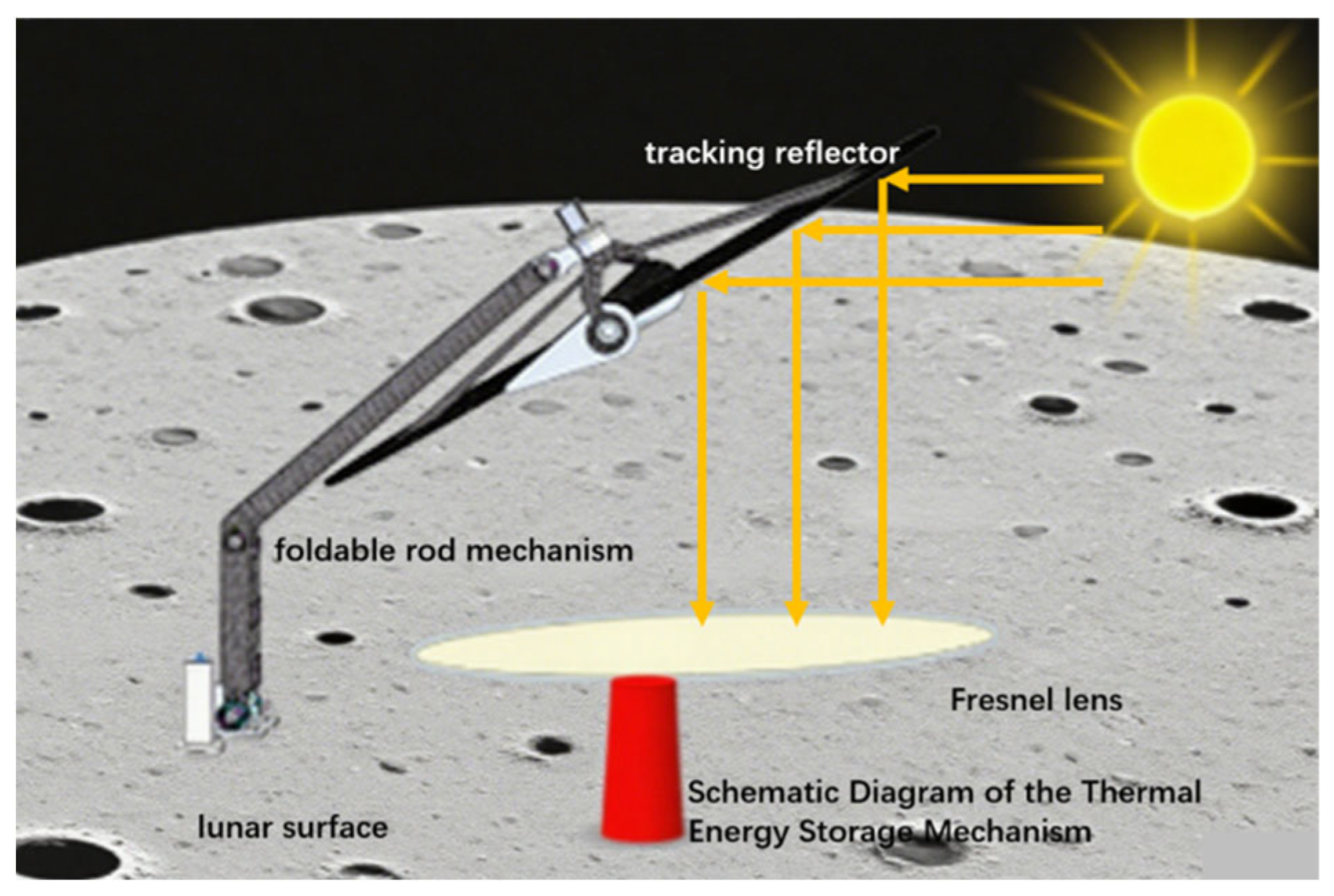
The structural design of the deployable concentrating mechanism is treated as a goal-oriented configuration synthesis problem rather than a simple engineering arrangement. The overall configuration of the proposed lunar surface solar concentrating system is illustrated in
Figure 1. For lunar surface operation, the mechanism must satisfy three coupled requirements: compact stowage under launch-volume constraints, autonomous deployment after landing, and stable reflector positioning for subsequent optical concentration. To resolve the conflict between the compact stowed dimension required during launch and landing and the large operational span required by the reflector-Fresnel concentrating system, a deployable topological configuration is required.
For the lunar surface scenario, the application requirements are translated into mechanism-level constraints, including compact stowage within the launch and landing envelope, low-shock non-pyrotechnic release, passive deployment under limited power availability, tolerance to a possible landing attitude deviation, and locked-state stiffness for maintaining the reflector posture.
Based on structural synthesis theory, a multi-link serial open-chain configuration is selected as the basic deployable topology. This topology decomposes the large operational workspace of the reflector into several revolute-link motions, thereby improving folded compactness while maintaining the required deployed reach. To reduce structural mass and avoid heavy active driving units at each joint, a “rigid locking + passive hinge drive” strategy is adopted. During launch and landing, the rigid locking device constrains the folded structure to withstand mechanical disturbances. After release on the lunar surface, the elastic strain energy stored in the passive spring hinges provides the deployment torque, enabling autonomous deployment without continuous external power input.
The deployment function and the optical tracking function are further decoupled in the configuration design. The planar reflector is supported by an L-shaped bracket, which separates the deployment trajectory workspace from the optical tracking workspace and reduces the risk of motion interference. After the support mechanism reaches the deployed state and is constrained by terminal positioning locks, the dual-axis azimuth-pitch motors are used only for solar tracking. In this way, passive deployment and optical operation are assigned to different functional stages of the mechanism.
2.2. Release Mechanism Design
The release mechanism determines the transition from the locked launch configuration to the deployable configuration, and therefore must satisfy both high-restraint and low-shock requirements. Because the optical concentrating reflector is sensitive to dynamic impact, traditional pyrotechnic separation devices are unsuitable for this application, as their high-frequency shock may lead to reflector misalignment or degradation of optical accuracy. A flexible thermal-knife restraint was considered during the preliminary screening stage; however, its release repeatability depends on rope pretension, thermal cutting reliability, and post-release retraction. These uncertainties may alter the initial deployment boundary condition of a passively driven multi-link mechanism. Therefore, this scheme is not adopted as the final release design.
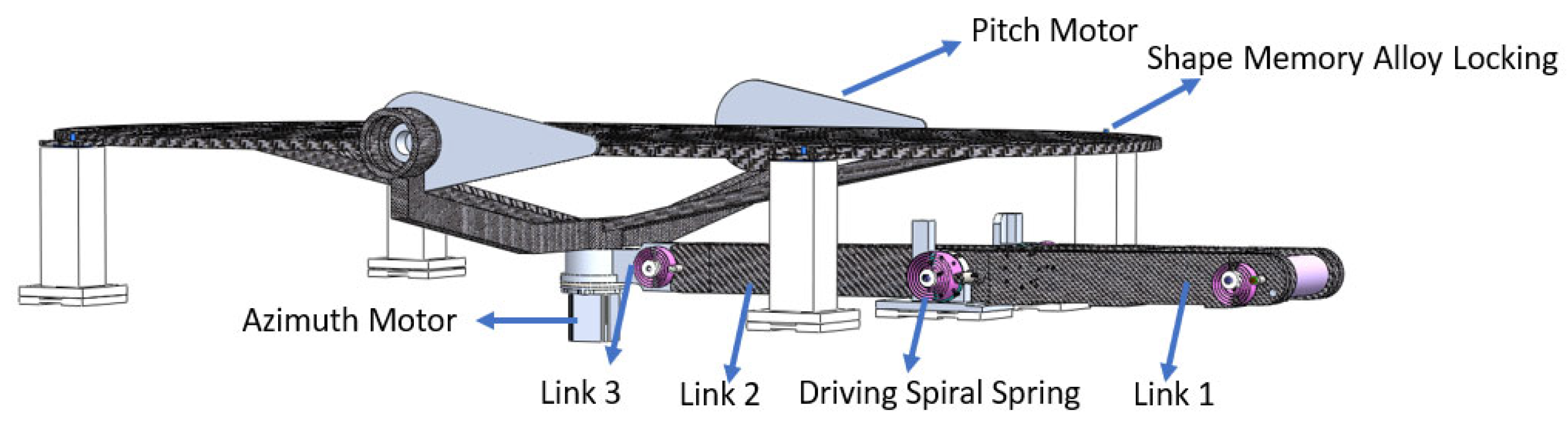
SMA-based release devices have potential advantages of compact structure and low release shock, which is consistent with the low-disturbance requirement of the lunar concentrating system. Accordingly, this study introduces an SMA-based locking concept as a preliminary hold-down and release approach for the folded deployable mechanism. The overall configuration of the energy-concentrating deployable mechanism with the SMA-based locking concept is shown in
Figure 2. During launch and landing, the locking interface is intended to constrain the reflector and the foldable rod mechanism as a stable folded assembly. After activation on the lunar surface, the SMA element undergoes phase-transformation-induced contraction, thereby releasing the constraint through a low-shock path. It should be noted that the present study does not provide a detailed hold-down and release mechanism design. In future prototype-level development, the degrees of freedom to be constrained or released, positioning repeatability, tolerance allocation, and deterministic constraint interfaces should be further investigated.
Following release, the spiral spring hinges convert stored elastic potential energy into deployment torque and drive the foldable rod mechanism to rotate toward the working configuration. When the prescribed terminal positions are reached, positioning pins constrain the deployment joints and transform the mechanism from a reconfigurable linkage into a locked support structure. Therefore, the SMA release device, passive spring hinges, and terminal positioning locks jointly define the launch restraint, deployment actuation, and post-deployment support boundary conditions of the mechanism.
2.3. Detailed Design and Mobility Analysis
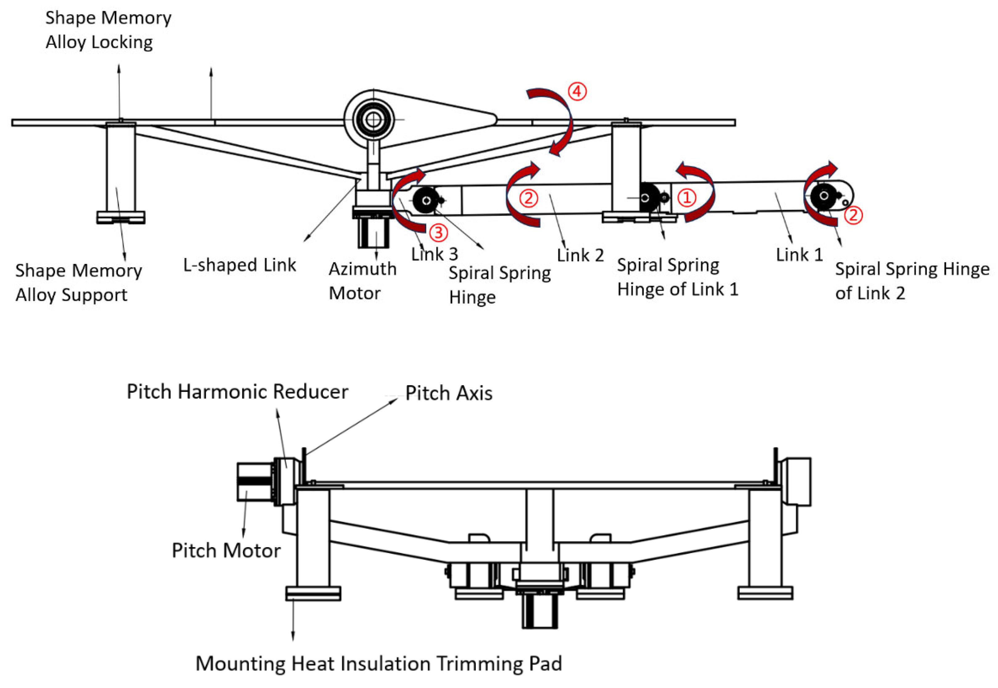
The detailed configuration of the concentrating foldable mechanism comprises three primary foldable links, namely Link 1, Link 2, and Link 3, which are interconnected by passive torsional spring hinges. The geometric lengths of the links are determined according to the folded-volume constraint and the required deployed operational dimensions, and are further optimized in
Section 5. The folded-state structural design is shown in
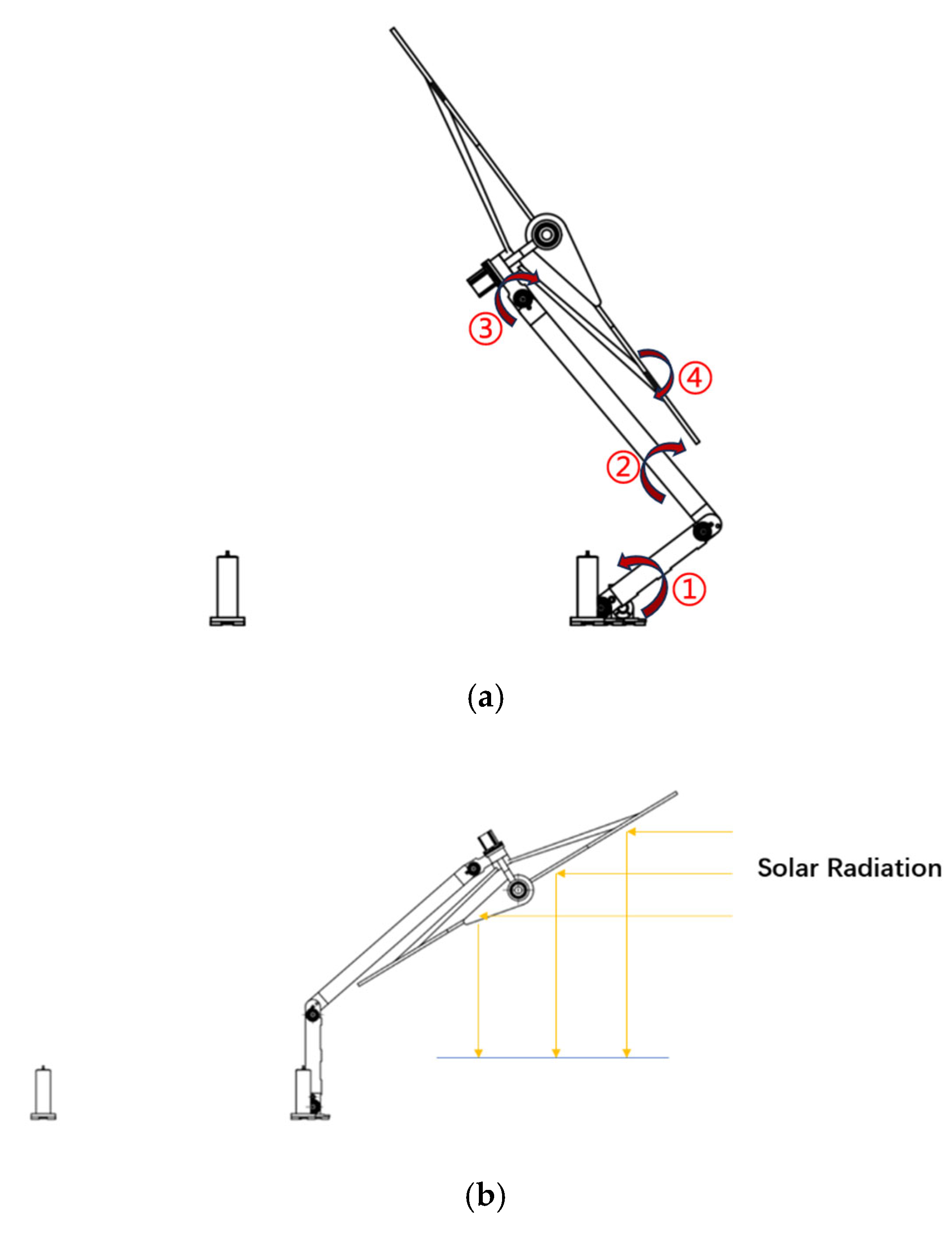
Figure 3. The numbered arrows in
Figure 3 indicate the deployment motion directions of Link 1, Link 2, and Link 3 driven by their corresponding torsional spring hinges, while arrow 4 indicates the motion tendency of the reflector-supporting assembly driven by the L-shaped link. During this passive deployment stage, the azimuth and pitch tracking axes remain locked; therefore, the reflector is transported from the folded position toward the working posture together with the L-shaped link, rather than being actively rotated by the tracking axes.
Figure 4 further illustrates the intermediate deployment state and the fully deployed operational configuration of the concentrating foldable mechanism.
To provide a theoretical basis for the subsequent kinematic modeling, the mobility of the deployment stage is evaluated using an equivalent planar open-chain model. During deployment, the azimuth-pitch tracking axes are locked, and Link 3, the L-shaped bracket, and the reflector are treated as one rigid body. Therefore, the deployable support can be simplified as a planar serial chain composed of a fixed base, three moving links, and three revolute pairs.
M = 3(N − 1) − 2J1 − J2,where N is the total number of links including the fixed base, J1 is the number of lower pairs, and J2 is the number of higher pairs. For the equivalent deployment model, N = 4, J1 = 3, and J2 = 0. Thus, M = 3(4 − 1) − 2 × 3 − 0 = 3.
This result indicates that the deployment stage can be described by three independent generalized coordinates corresponding to the rotations of the three passive spring hinges. The passive hinges provide the associated driving torques, while the terminal positioning locks constrain these deployment degrees of freedom after full extension. The mechanism is therefore transformed from a reconfigurable open-chain system into a locked support structure for subsequent dual-axis solar tracking.
3. Kinematic Analysis of the Mechanism
The purpose of the kinematic analysis is to establish the mapping relationship between the hinge rotations of the deployable support and the spatial position of the concentrating reflector. This analysis provides the theoretical basis for deployment trajectory planning, dynamic modeling, and subsequent parameter optimization. During the deployment stage, the azimuth-pitch tracking axes are locked, and the reflector, L-shaped bracket, and terminal link are treated as a rigidly connected body. Therefore, the deployable mechanism can be simplified as an equivalent planar serial linkage composed of revolute joints and rigid links. In this section, the deployment process is first constrained by motion-envelope analysis, and then the kinematic model is established using vector-loop formulation and forward kinematic verification.
3.1. Deployment Analysis of the Concentrating Mechanism
The proposed concentrating mechanism is passively driven by spring hinges during deployment. Unlike an actively controlled multi-joint system, the passive deployment process is more sensitive to the initial release state, joint coordination, and link-reflector interference. Therefore, the deployment path must be planned before dynamic modeling to ensure that the moving links remain within the allowable motion envelope.
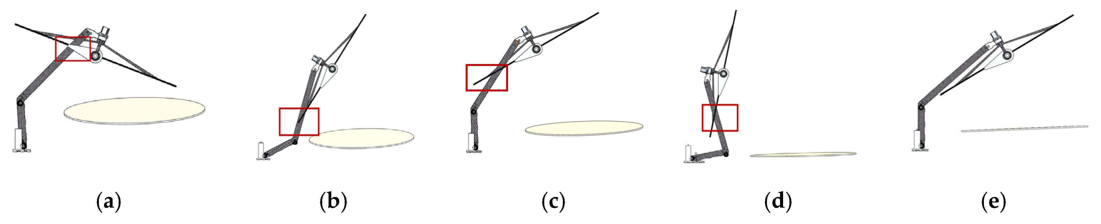
Several representative deployment configurations are shown in
Figure 5. Configurations (a)–(d) correspond to possible interference states, in which the reflector or supporting links violate the allowable deployment envelope. Configuration (e) represents the desired deployment state. These configurations indicate that the deployment problem should not be treated only as a geometric unfolding process but as a constrained motion-planning problem for a coupled linkage.
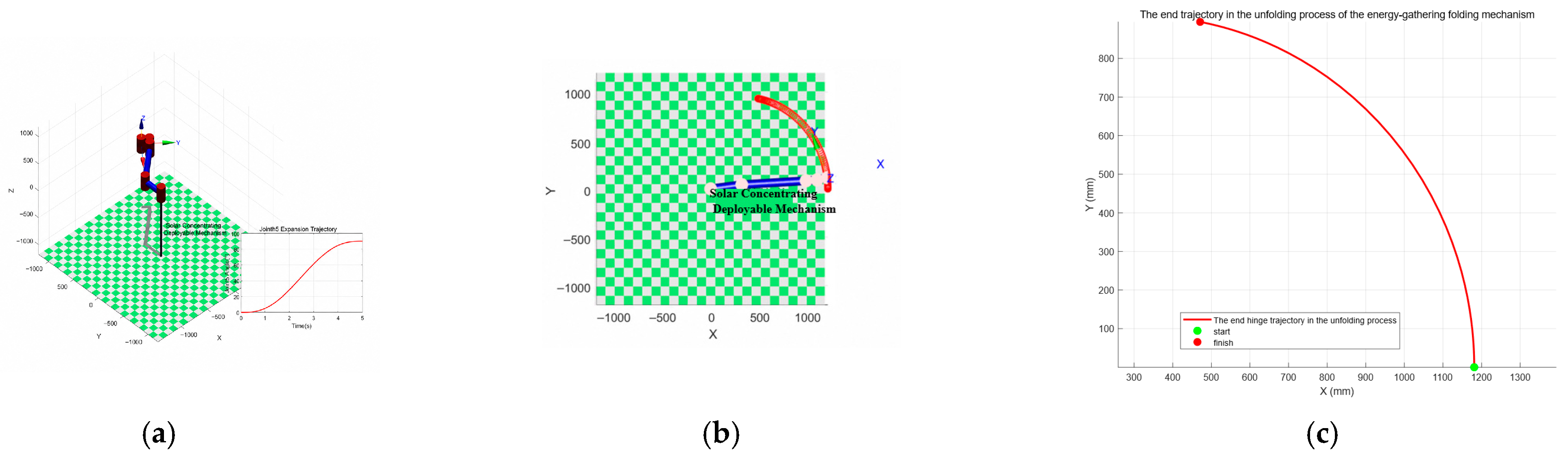
Taking the interference-free configuration as the target state, the deployment trajectory of the mechanism is planned by constraining the motion envelope of the terminal link and the reflector. The planned deployment path is shown in
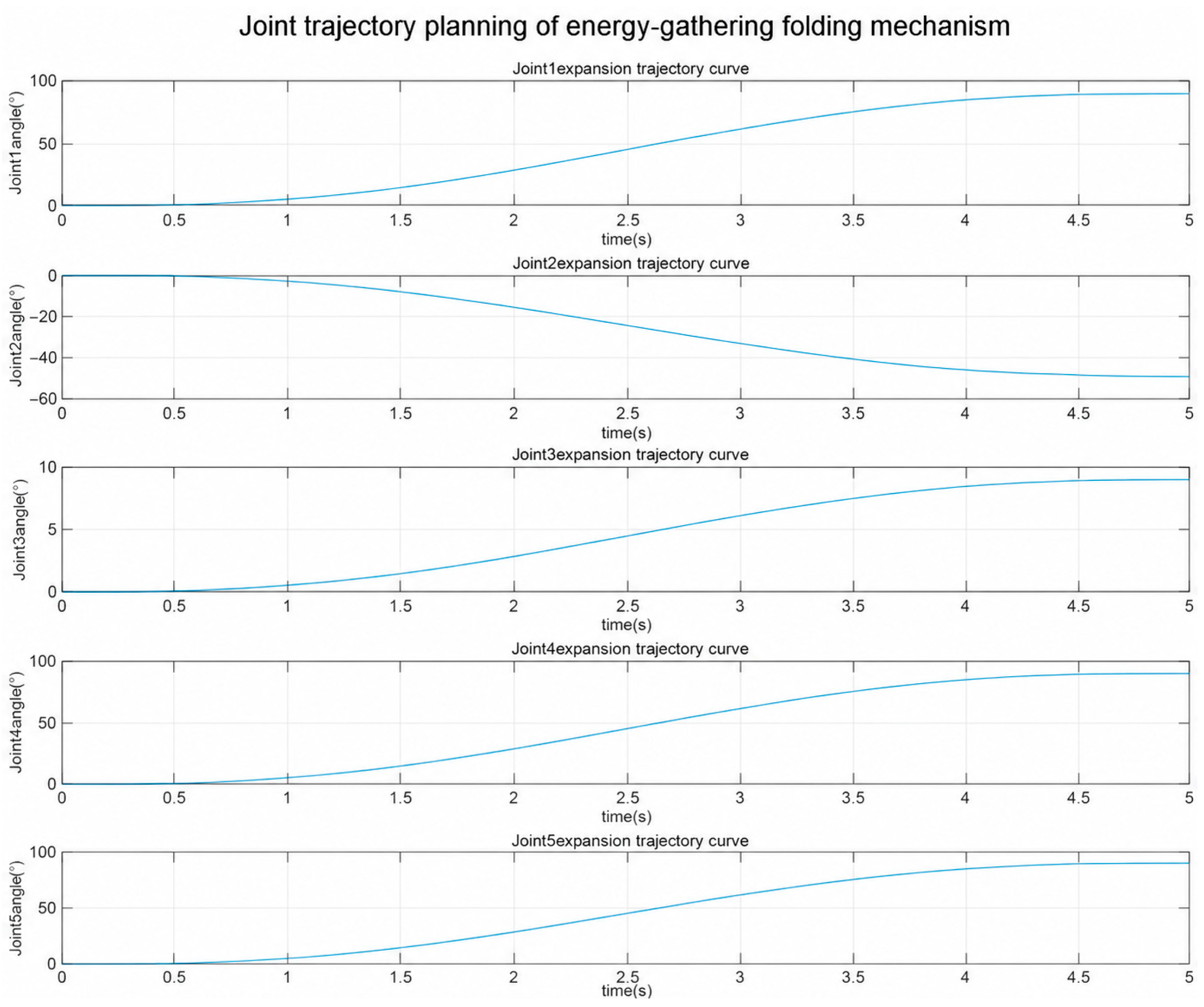
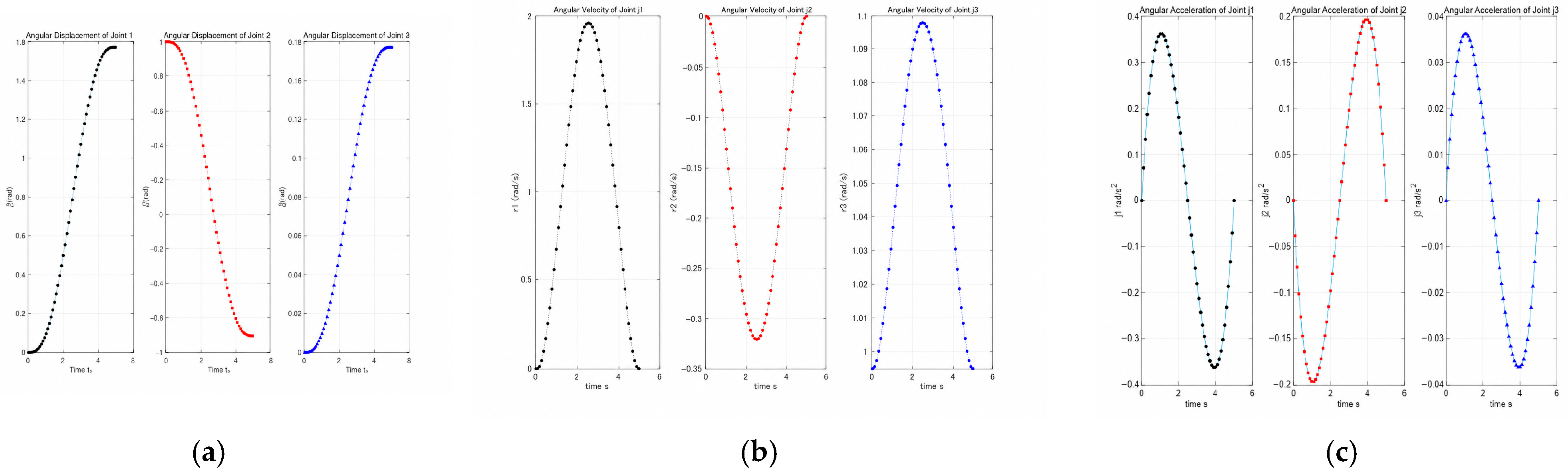
Figure 6, where the end-joint trajectory and the reflector displacement envelope are used to evaluate the feasibility of the deployment motion. The corresponding joint-angle planning curves are shown in
Figure 7. These curves provide the prescribed kinematic inputs for the subsequent vector analysis and dynamic simulation.
3.2. Deployment Process Simplification and Vector-Based Kinematic Model
To establish an analytical kinematic model, the deployable support is simplified according to the following assumptions: the links are treated as rigid bodies, the passive hinges are modeled as ideal revolute joints, the geometric dimensions of the hinge connectors are neglected, and the tracking motors remain locked during deployment. The resulting simplified model of the concentrating foldable mechanism in the folded state is shown in
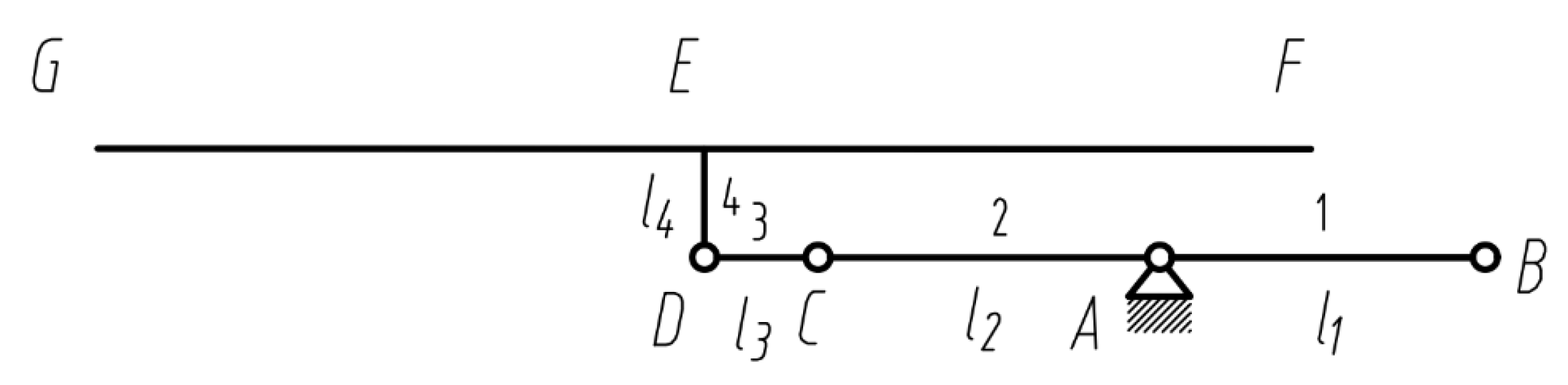
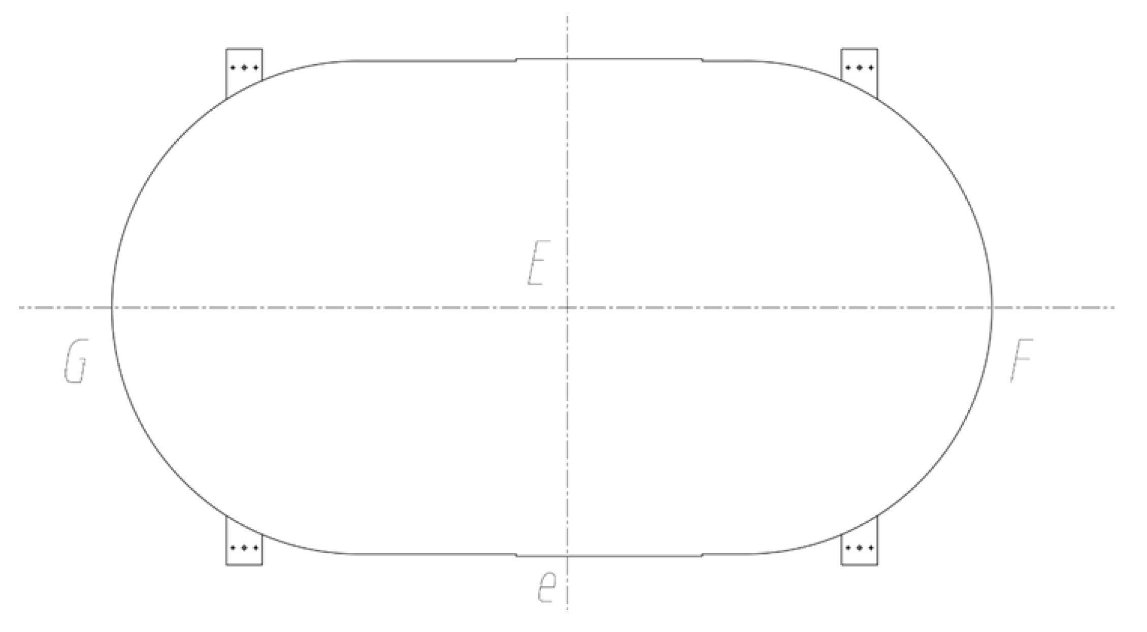
Figure 8, and its top view is presented in
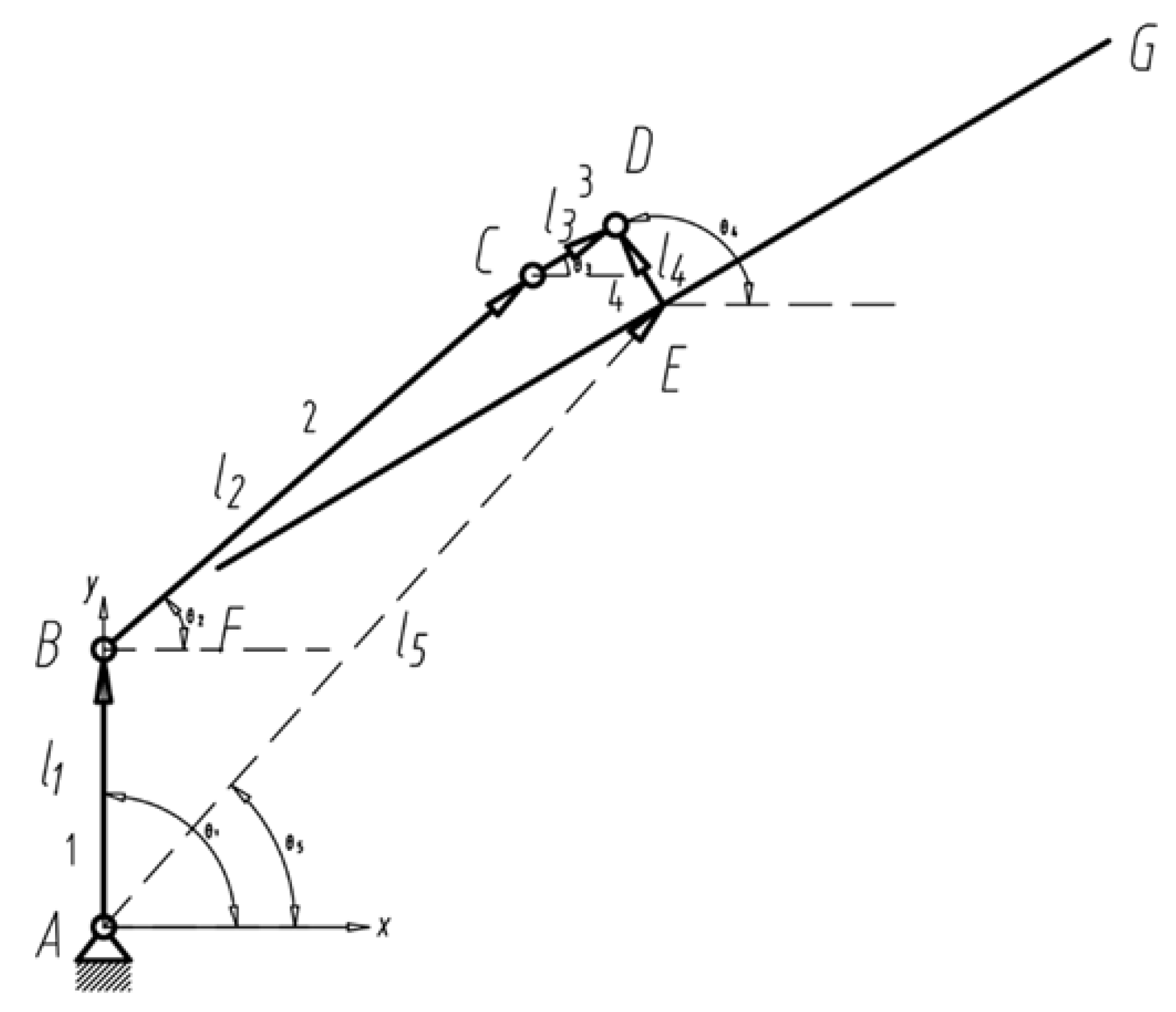
Figure 9. Under these assumptions, Rod 1, Rod 2, and Rod 3 are represented by line segments AB, BC, and CD, respectively. The L-shaped bracket connecting Rod 3 and the reflector is represented by segment DE, and the reflector is treated as a rigid body attached to the terminal link.
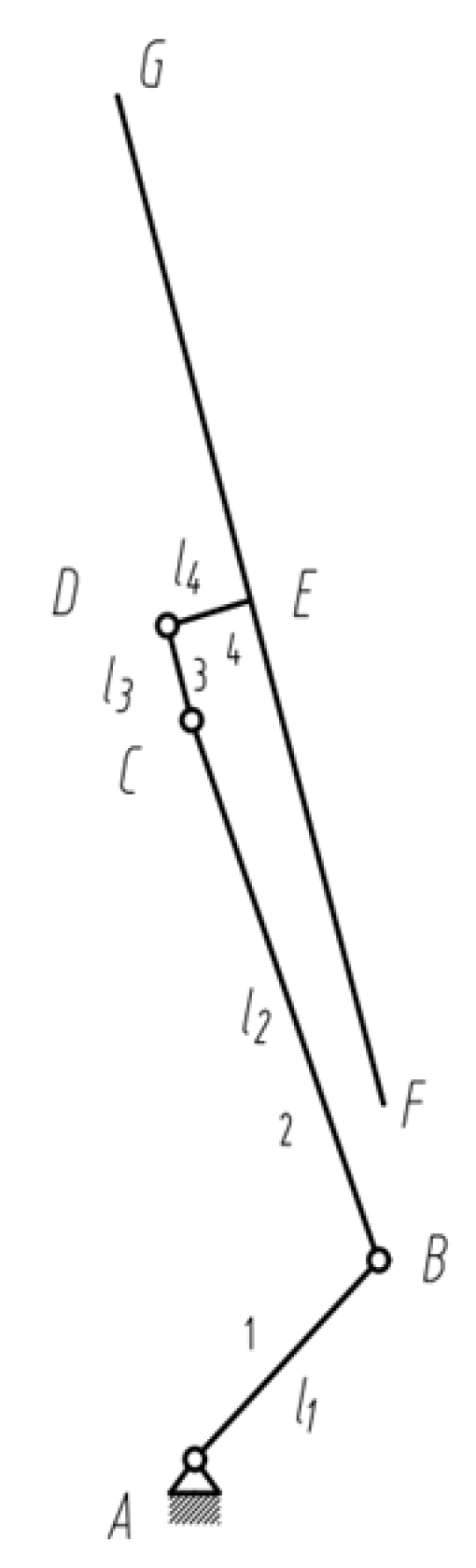
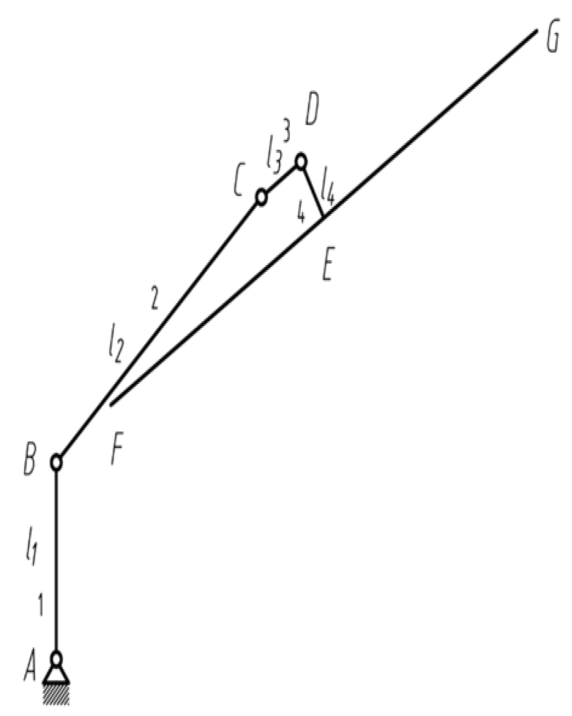
The intermediate and final deployment states are shown in
Figure 10 and
Figure 11, respectively. These two states define the geometric boundary conditions of the deployment process and are used to determine the initial and terminal configurations of the kinematic model.
Taking point A as the origin, a Cartesian coordinate system is established for the equivalent planar linkage. The vectors, link orientation angles, and key points of the mechanism are defined in
Figure 12, and the coordinates of the main points are listed in
Table 1.
The vector-loop method is then used to describe the position relationship among the links. By connecting points A, B, C, D, and E, the vector loop of the equivalent linkage can be written as:
It should be noted that this vector loop is an auxiliary geometric closure constructed to determine the centroid position of the reflector. It does not represent an actual closed-chain constraint of the deployable support, which remains an equivalent planar open-chain mechanism during deployment. In this formulation, is the position vector from the fixed base point to the reflector centroid , rather than a physical structural link. Therefore, and are dependent variables that vary with the prescribed link orientation angles.
The above equation is expressed in the complex form as:
where all vector orientation angles are measured counterclockwise from the positive direction of the global
X-axis. By expanding the complex equation using Euler’s formula and equating the real and imaginary parts, the scalar position equations of the mechanism can be obtained as:
In these equations, are known structural dimensions, and are the prescribed absolute orientation angles of the corresponding vectors. The magnitude and orientation angle of the auxiliary position vector are dependent variables to be determined.
To avoid ambiguity in the subsequent derivation, the auxiliary position vector
is decomposed into its Cartesian components. By rearranging Equations (4) and (5), these components are obtained as
where
and
are the horizontal and vertical components of
, respectively. Therefore, the orientation angle and magnitude of the auxiliary position vector can be obtained as:
Accordingly, the position components of the reflector centroid are given by:
By differentiating the displacement equation with respect to time, the velocity and acceleration of the reflector centroid are obtained as:
The velocity of the centroid is:
The acceleration of the centroid is:
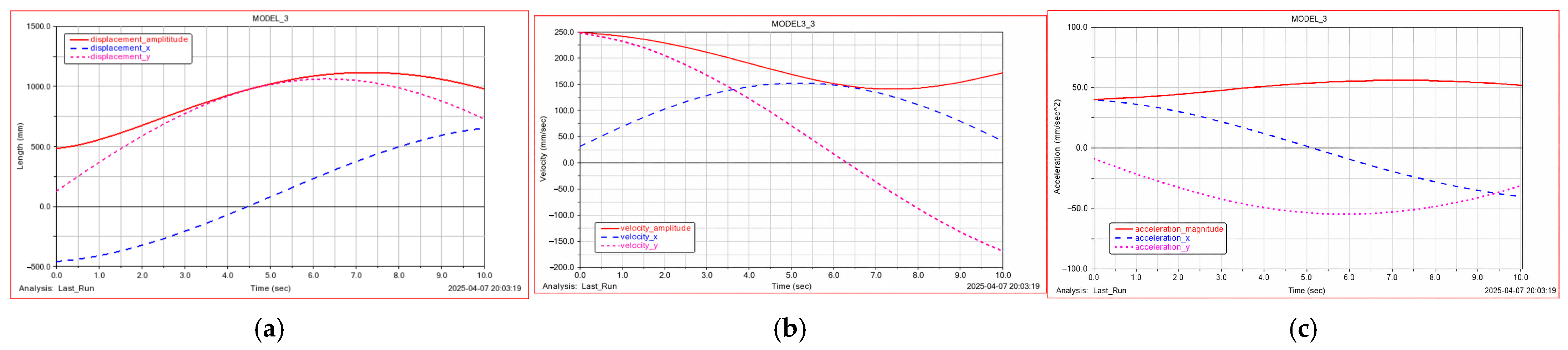
To examine the consistency of the analytical kinematic solution, a corresponding numerical model is established using the same geometric parameters and prescribed joint-angle inputs. In this model, the passive spring–hinge joints are represented by equivalent revolute joint drives at points
,
, and
. The displacement, velocity, and acceleration responses of the reflector centroid are extracted and compared with the analytical predictions obtained from Equations (8)–(10). As shown in
Figure 13, the numerical responses show the same variation trends as the theoretical results, indicating that the established kinematic model can describe the main deployment motion of the reflector centroid. The continuous centroid responses also suggest that the planned trajectory does not introduce abrupt kinematic changes during deployment.
3.3. Forward Kinematic Model and Numerical Verification
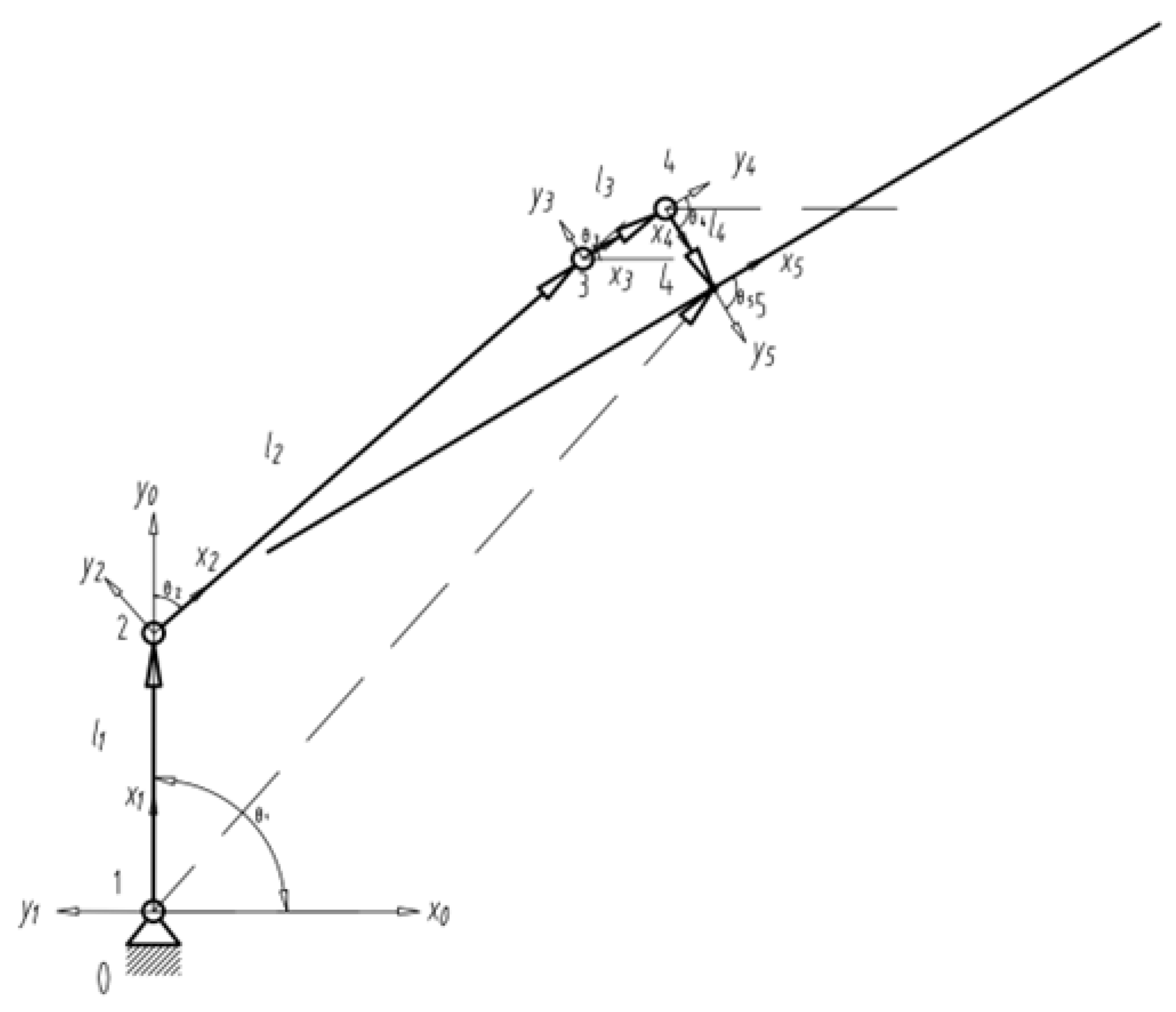
To further verify the consistency of the vector-based kinematic formulation, an equivalent forward kinematic model is established. The deployable support is modeled as a planar open-chain linkage with revolute joints, and joint coordinate systems are assigned along the deployment chain. The Denavit–Hartenberg (D-H) parameters of the equivalent joints are listed in
Table 2, and the corresponding coordinate systems are shown in
Figure 14.
The homogeneous transformation matrix between adjacent coordinate systems can be written as:
Joint Coordinate System
can be obtained by rotating from Joint Coordinate System
, and the homogeneous transformation matrix
A between them is:
Joint Coordinate System
can be obtained by rotating from Joint Coordinate System
, and the homogeneous transformation matrix
between them is:
Joint Coordinate System
can be obtained by rotating from Joint Coordinate System
, and the homogeneous transformation matrix
between them is:
Joint Coordinate System
can be obtained by rotating from Joint Coordinate System
, and the homogeneous transformation matrix
between them is:
Joint Coordinate System
can be obtained by rotating from Joint Coordinate System
, and the homogeneous transformation matrix
between them is:
Joint Coordinate System
can be obtained by rotating from Joint Coordinate System
, and the homogeneous transformation matrix
between them is:
By multiplying the adjacent homogeneous transformation matrices, the pose of the terminal link and the reflector can be obtained. This forward kinematic model provides an independent verification route for the vector-loop solution and confirms whether the planned joint-angle inputs can reproduce the desired deployment trajectory.
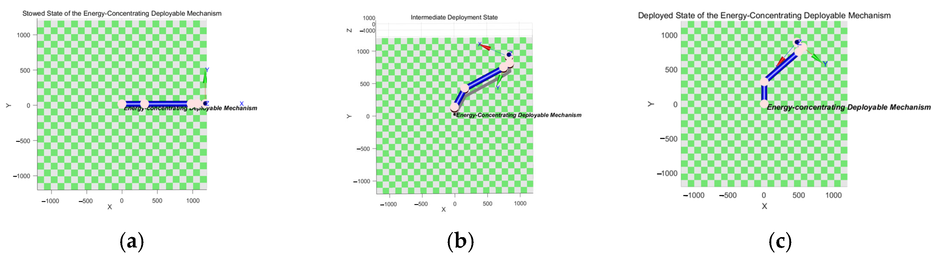
The folding, intermediate, and fully deployed states obtained from the forward kinematic model are shown in
Figure 15. The simulated deployment sequence is consistent with the planned motion path, indicating that the equivalent kinematic model can describe the main deployment behavior of the mechanism.
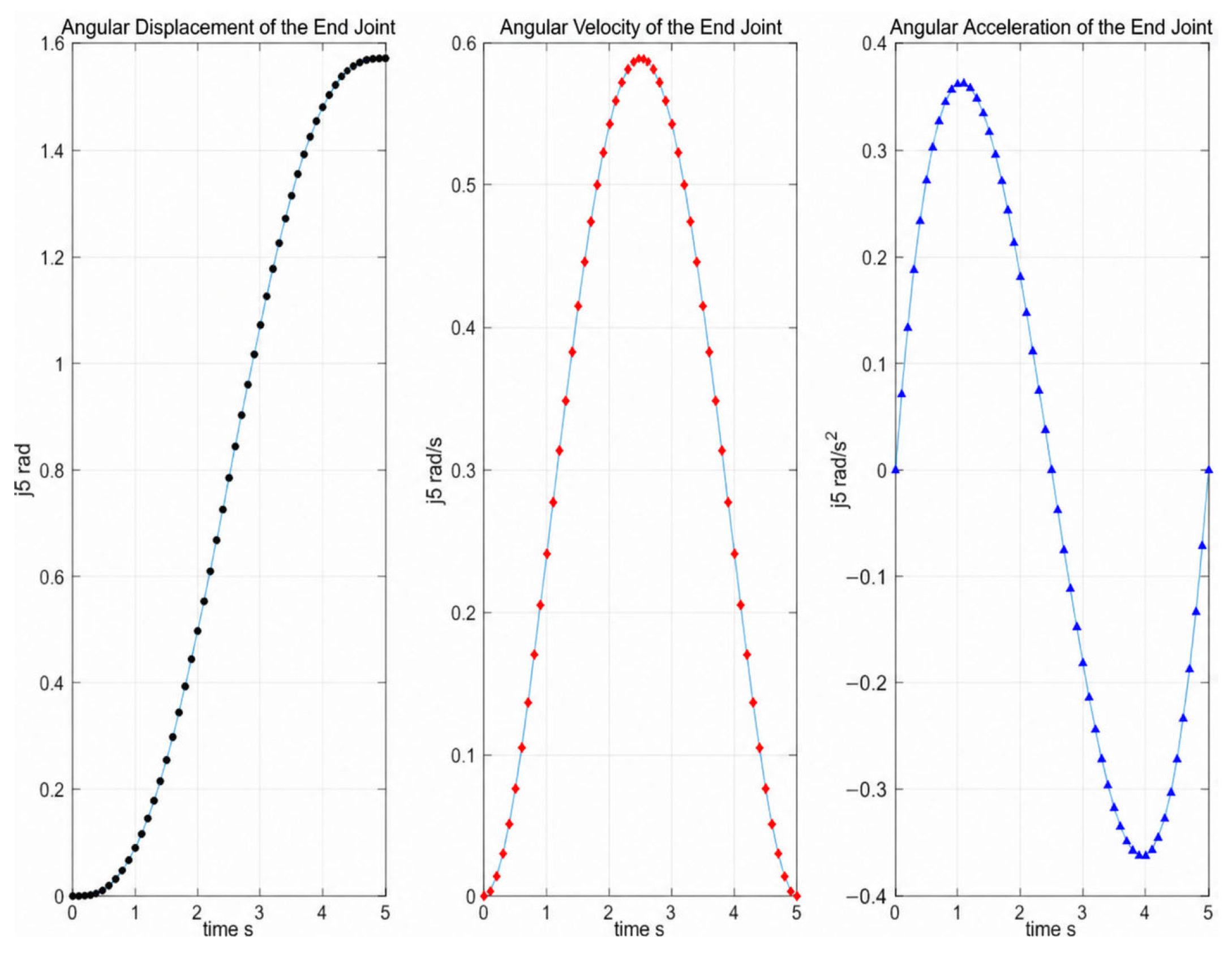
The motion curves of the terminal joint are shown in
Figure 16. The curves provide displacement-level verification of the planned trajectory and serve as the input basis for the subsequent dynamic analysis.
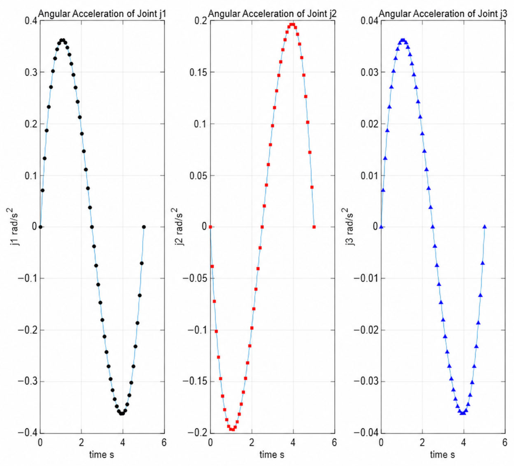
The first three deployment joints correspond to the passive spring–hinge joints of the mechanism. Their angular acceleration curves are shown in
Figure 17. The absence of abrupt discontinuities in the acceleration curves indicates that the planned trajectory does not introduce sudden kinematic changes during deployment. Therefore, the kinematic model provides a feasible basis for the dynamic response analysis and driving-torque evaluation in
Section 4.
5. Multi-Objective Parameter Optimization Design of the Mechanism Based on the Non-Dominated Sorting Genetic Algorithm (NSGA-II)
The core function of the energy-concentrating deployable mechanism is to achieve reliable deployment and energy concentration in space. The deployment performance of the concentrating foldable mechanism is affected by the geometric parameters of the links and the stiffness parameters of the passive spring hinges. The link lengths determine the folded envelope, deployed configuration, and reflector centroid trajectory, while the spring stiffness parameters influence the equivalent hinge torque and motion smoothness during deployment. In the present optimization model, deployment smoothness and synchronization accuracy are selected as the primary optimization objectives. Specifically, the acceleration response of the reflector centroid is used to characterize deployment smoothness, and the joint-angle deviation from the planned deployment trajectory is used to evaluate synchronization accuracy. The hinge torque response, torque fluctuation, deployment ratio, and structural compactness are further evaluated as post-optimization performance indicators rather than being directly included in the objective functions. Under the prescribed geometric and dynamic constraints, the non-dominated sorting genetic algorithm II (NSGA-II) is adopted to obtain a set of Pareto-optimal solutions that balance smooth deployment and synchronized motion.
5.1. Optimization Objectives and Design Variables
According to the structural configuration and dynamic response analyzed in the previous sections, the link lengths and spring stiffness parameters are selected as design variables. The link lengths determine the folded envelope, deployed reflector position, and centroid trajectory, while the spring stiffness parameters affect the hinge driving torque and deployment smoothness. Therefore, these variables are used to optimize the deployment performance of the mechanism, as listed in
Table 4. The spring stiffness variables listed in
Table 4 correspond to the equivalent torsional stiffness parameters used in the spring–hinge joint model described in
Section 4.2.1.
In the optimization process, only the effective lengths of Link 1, Link 2, and Link 3 are selected as design variables, while the link cross-sectional profiles, material properties, and joint configurations are kept unchanged. Therefore, the link profiles do not scale linearly with the optimized lengths. For each candidate design, the mass properties and inertia parameters are recalculated according to the updated link lengths under the assumption of uniform material distribution and constant cross-sectional dimensions, and the interference-free deployment envelope is checked using the same geometric model described in
Section 3. This assumption allows the influence of link-length variation on the deployment performance to be evaluated independently.
A multi-objective function is established to achieve the optimization objectives of improving the trajectory smoothness and motion stability of the concentrating foldable mechanism while reducing the synchronous deployment error. To evaluate the deployment smoothness, the acceleration response of the reflector centroid is selected as one objective index. A smaller centroid acceleration indicates a smoother deployment process and lower inertial disturbance to the reflector.
Among them,
and
are the centroid accelerations of the concentrating reflector in the X and Y directions, respectively, and
is the total deployment time of the mechanism. Where the acceleration components of the reflector centroid and the total deployment time are defined according to the kinematic model in
Section 3.
The synchronization error of the mechanism reflects the deviation between the actual deployment trajectory and the ideal trajectory, which is defined as the integral of the sum of squares of the angular displacement deviations of the first three joints:
Among them, is the ideal angular displacement of the i-th joint, and is the actual angular displacement. These are used to quantify the trajectory tracking deviation during deployment.
Meanwhile, to ensure the physical feasibility and deployment reliability of the concentrating foldable mechanism, the following constraint conditions are set:
Geometric constraints: The length of each link must meet the mechanism dimensions after deployment, match the installation space, and avoid mutual interference:
, In addition to the length constraints, the interference-free condition is checked using the deployment envelope established in
Section 3; Dynamic constraints: To limit inertial disturbance during deployment, the peak angular acceleration of each joint is constrained as:
.
5.2. Algorithm Implementation Process
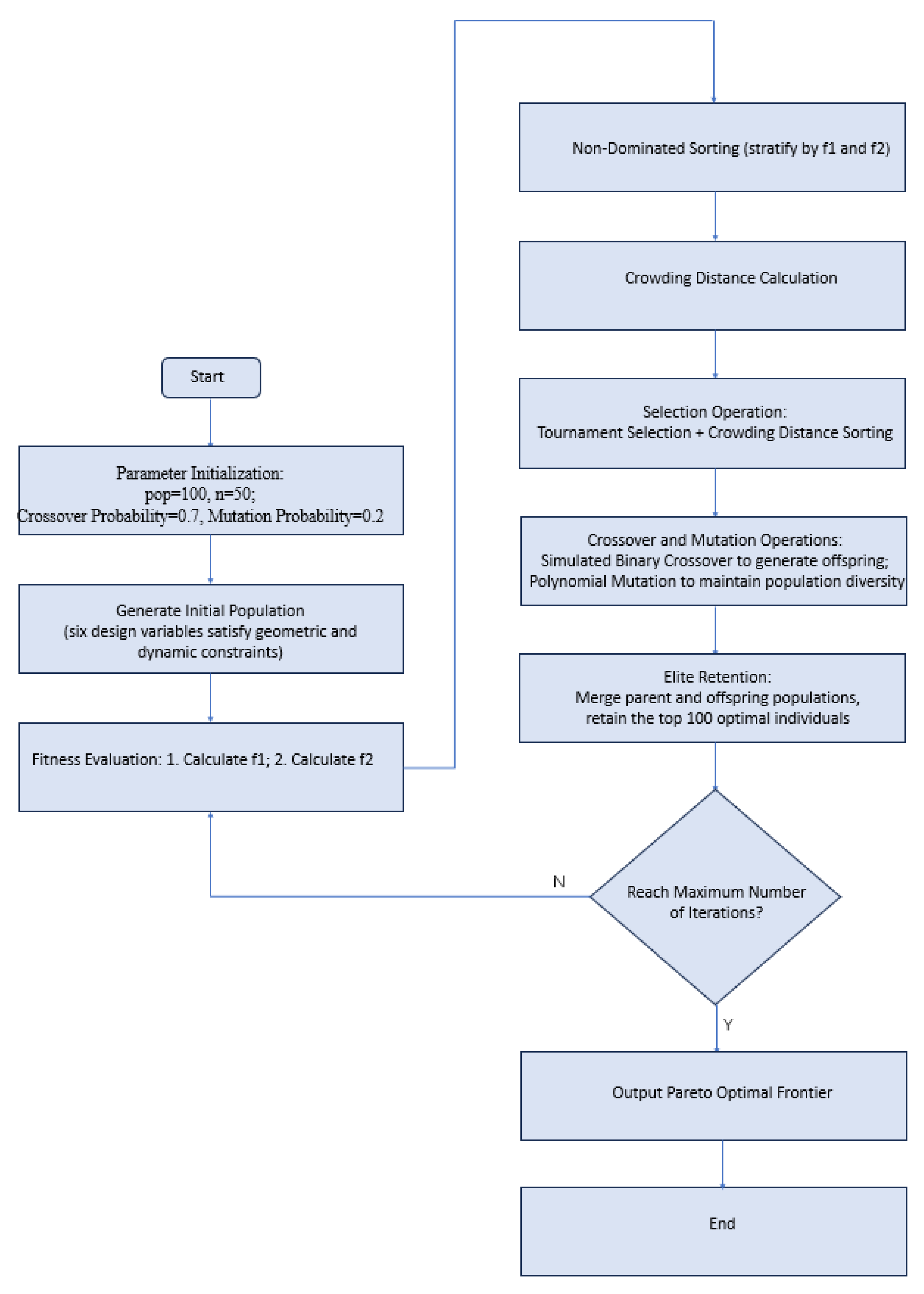
The NSGA-II procedure is implemented to solve the above multi-objective optimization problem. The initial population is generated within the feasible ranges of the design variables. Each individual contains the link-length and spring-stiffness parameters, and its objective values are calculated using the kinematic and dynamic models established in the previous sections. Non-dominated sorting and crowding-distance calculation are then used to rank the individuals and maintain population diversity. Tournament selection, crossover, mutation, and elite retention are performed iteratively until the maximum generation number is reached.
In this study, the population size is set to 100, the crossover probability is 0.7, the mutation probability is 0.2, and the maximum number of generations is 50. The optimization procedure is shown in
Figure 23.
5.3. Pareto-Front Analysis and Solution Selection
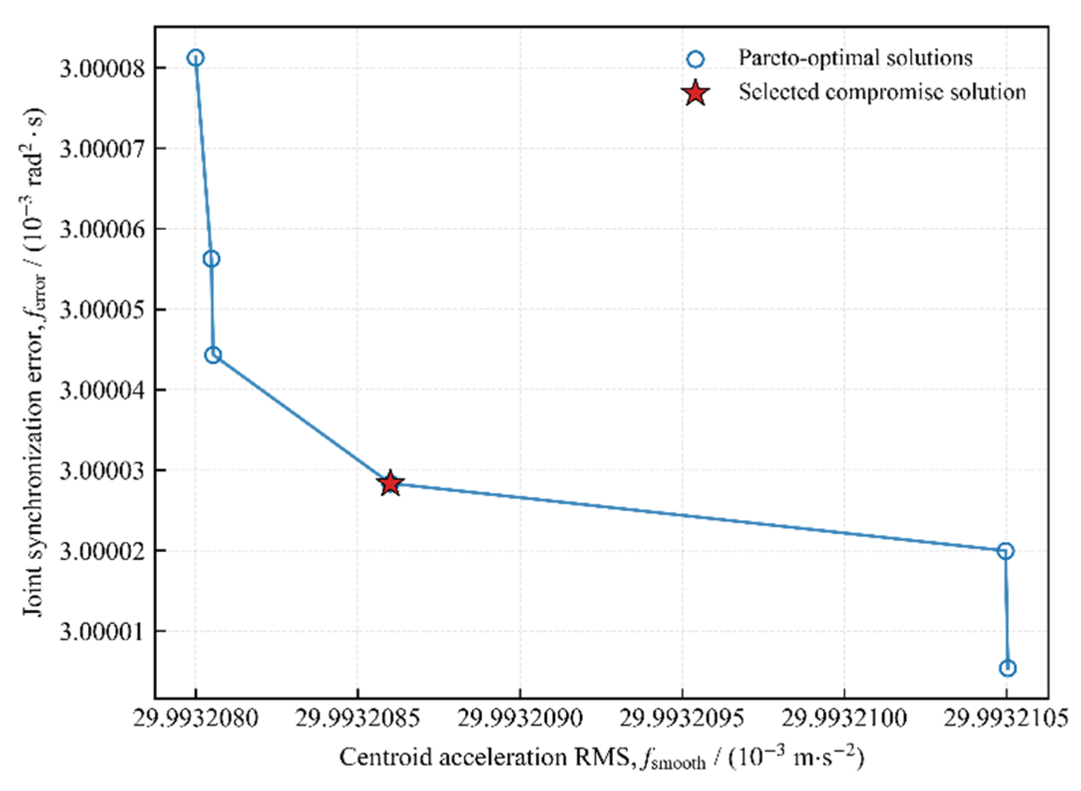
The Pareto frontier obtained from the multi-objective optimization is shown in
Figure 24. The frontier contains 14 non-dominated solutions, indicating that no single solution can simultaneously minimize all objective functions. Therefore, the final design should be selected by balancing deployment smoothness, synchronization accuracy, and structural feasibility.
Among the Pareto-optimal solutions, the third solution is selected as the final optimized parameter set because it provides a balanced compromise between centroid acceleration and synchronization error while satisfying the geometric constraints of the folded and deployed configurations. The selected optimization result is listed in
Table 5.
5.4. Verification of the Optimized Parameters
The original and optimized parameters are compared in
Table 6. After optimization, the folded and deployed dimensions of the mechanism are recalculated to evaluate the deployment ratio. The maximum deployment ratio increases from 5.6 to 7.2, corresponding to an increase of 28.57%.
Before optimization, the maximum deployment ratio of the mechanism occurs in the H direction, which is 5.6. After optimization, the dimensions of the concentrating deployable mechanism in the folded state are: ; and the dimensions in the deployed state are ; the maximum deployment ratio appears in the H direction at 7.2, the minimum deployment ratio appears in the V direction at 1, and the maximum deployment ratio is increased by 28.57%.
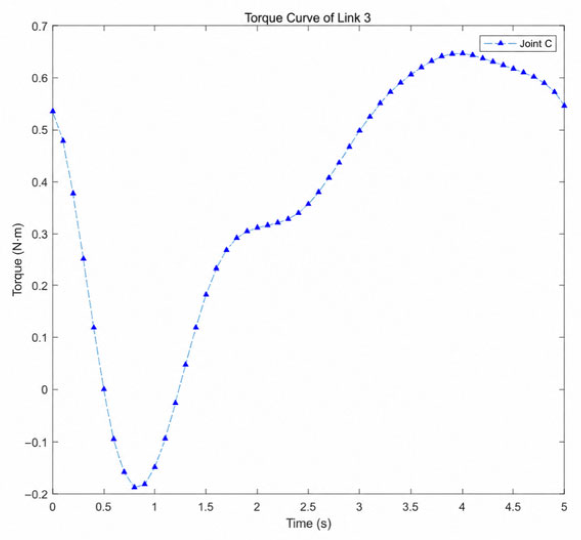
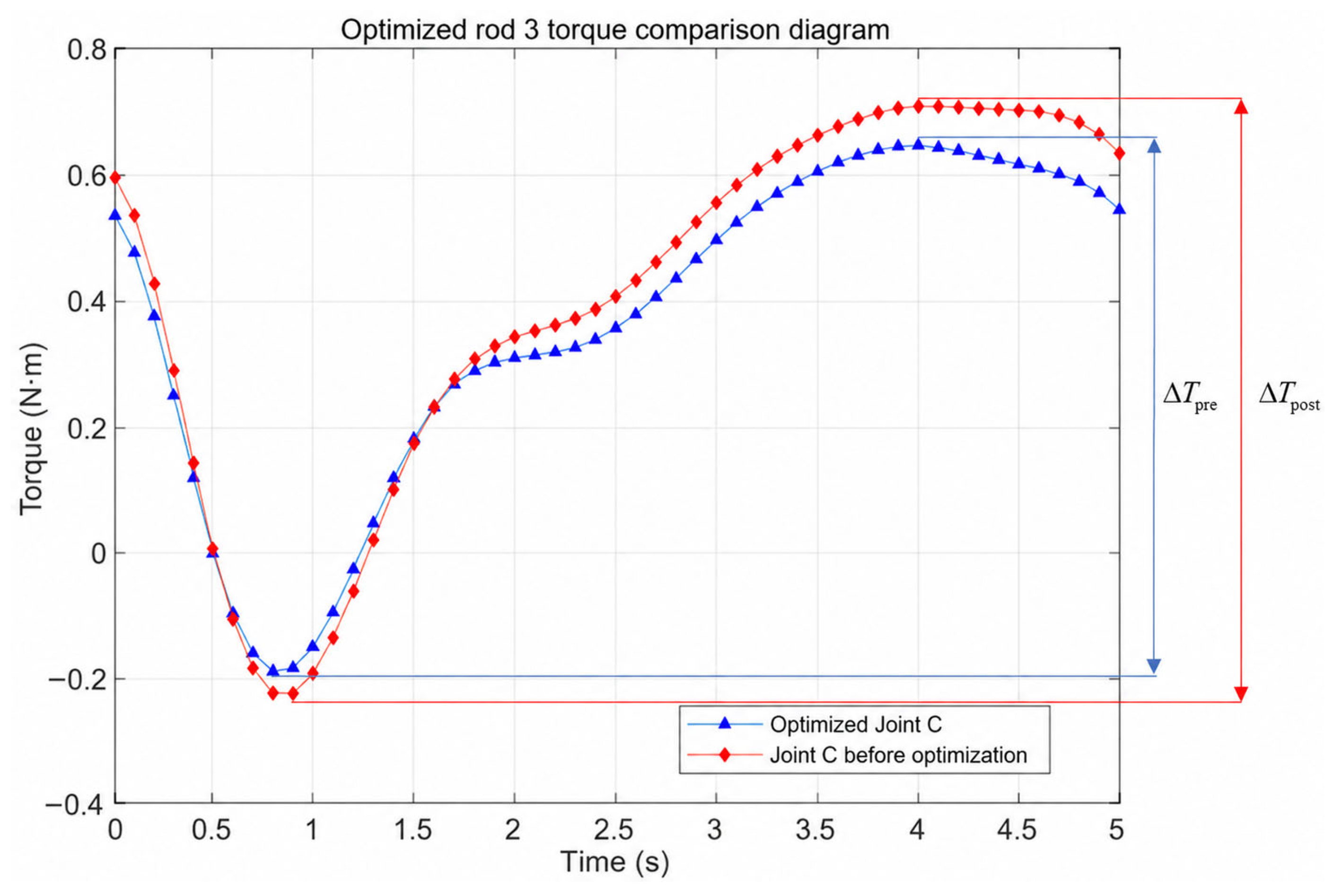
The driving torque responses of Link 3 before and after optimization are compared in
Figure 25: the peak torque reduction amplitude
is calculated according to Equation (41), decreasing by 10.9%.
The torque fluctuation amplitude
, calculated according to Equation (42), is reduced by 9.7%.
The total link-length reduction is denoted by
and calculated as
using the following formula:
where
and
are the lengths of Link
before and after optimization, respectively. According to the optimized parameters, the total link length decreases from
to
, corresponding to a total link-length reduction of
The multi-objective optimization results show that the optimized mechanism achieves better deployment performance under the prescribed trajectory and idealized joint assumptions. The maximum deployment ratio in the -direction increases from 5.6 to 7.2, corresponding to an improvement of 28.57%. The peak driving torque of Link 3 is reduced by 10.9%, and the torque fluctuation amplitude is reduced by 9.7%. Meanwhile, the total link length decreases from to , corresponding to a total link-length reduction of 4.46%. These improvements indicate that the optimized design reduces the deployment torque demand and enhances the compactness of the deployable mechanism, while maintaining smooth and synchronized deployment behavior.
6. Discussion and Conclusions
This study proposed a passive multi-link deployable support mechanism for lunar surface solar-concentrating systems. The mechanism was designed to satisfy the requirements of compact stowage, passive deployment, terminal locking, and stable reflector support. A hybrid reflector-Fresnel concentrating configuration was considered, and the foldable support was formulated as a reconfigurable linkage system connecting the stowed state and the optical working state.
The results show that the “rigid locking + passive spring–hinge drive” strategy can provide a feasible deployment scheme with reduced drive complexity. Based on the motion-envelope planning and vector-based kinematic analysis, the deployment trajectory of the reflector centroid was obtained, and the relationship between the link motion and reflector working posture was clarified. This provides a theoretical basis for avoiding link-reflector interference during deployment.
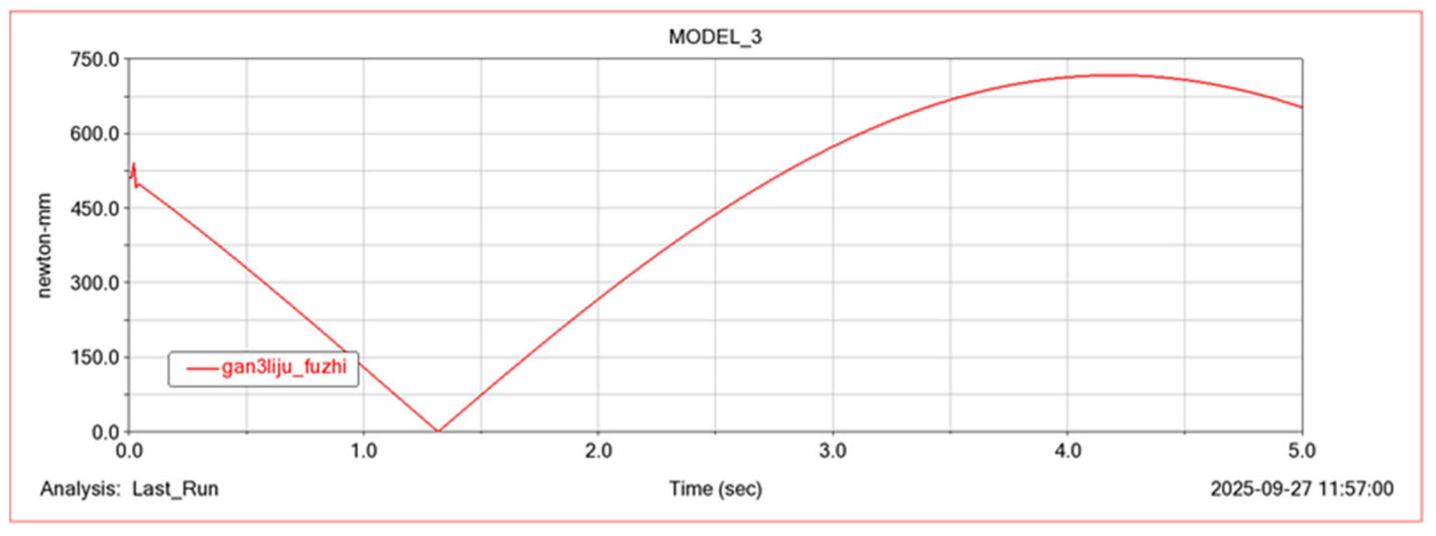
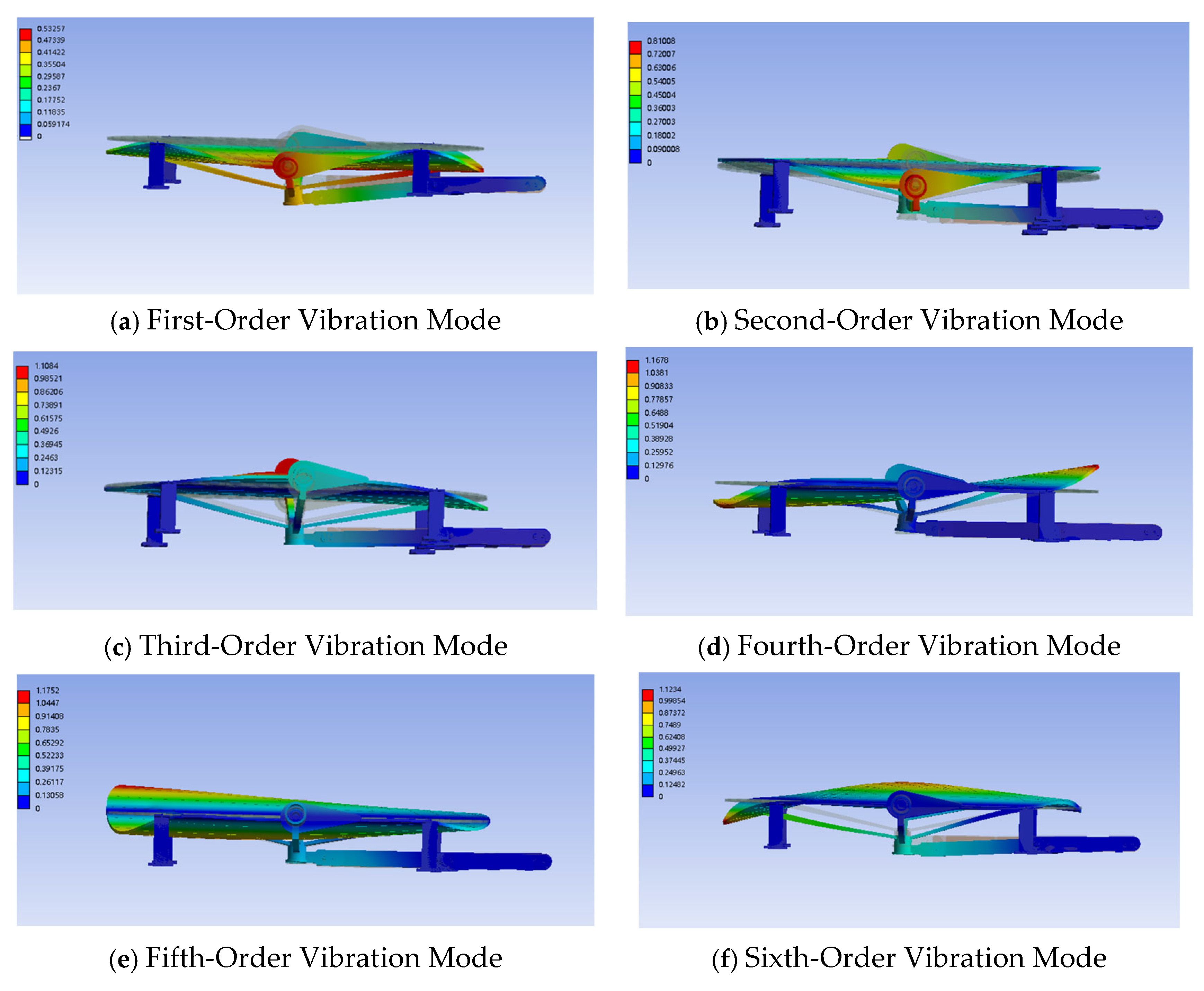
Dynamic modeling and numerical simulation further verified the deployment performance of the mechanism. The simulated driving torque of Link 3 varied within 0–0.70 N·m, while the analytical result varied within 0–0.68 N·m, giving a relative peak-value error of 2.8%. The maximum angular acceleration during deployment was approximately 0.08 rad/s2, indicating that the planned deployment trajectory does not introduce severe inertial disturbance under the adopted modeling assumptions. The finite-element modal analysis showed that the first natural frequency of the locked mechanism was 54.969 Hz, suggesting that no obvious low-frequency global flexible mode appears in the modeled locked-state configuration.
The multi-objective optimization results further improved the deployment performance and structural compactness. Based on the selected Pareto-optimal solution, the maximum deployment ratio increased from 5.6 to 7.2, corresponding to an improvement of 28.57%. The maximum driving torque of Link 3 was reduced by 10.9%, the torque fluctuation amplitude was reduced by 9.7%, and the total link length decreased from 1.121 m to 1.071 m, corresponding to a reduction of 4.46%. These results indicate that the optimized design can reduce deployment torque demand while maintaining smooth and synchronized deployment behavior.
From an engineering perspective, the proposed mechanism provides a compact and passively driven support scheme for lunar deployable concentrating systems. The analytical modeling, dynamic verification, and parameter optimization establish a preliminary design route for prototype-level deployable concentrating mechanisms. However, the present study is still limited to theoretical modeling and numerical verification. Future work will focus on prototype fabrication, deployment experiments, hold-down/release constraint allocation, joint clearance and friction modeling, harness routing for the azimuth and pitch motors, thermal-vacuum effects, lunar dust influence, and optical-mechanical integrated verification under lunar surface operating conditions.