Article

Comparative Numerical Investigation of Gravitational and Impulse Store Separation in Highly Subsonic Flow


1
Military Technical Institute, 11030 Belgrade, Serbia
2
Faculty of Mechanical Engineering, University of Belgrade, 11000 Belgrade, Serbia
*
Author to whom correspondence should be addressed.
Aerospace 2026, 13(4), 336; https://doi.org/10.3390/aerospace13040336
Submission received: 13 February 2026 / Revised: 19 March 2026 / Accepted: 31 March 2026 / Published: 2 April 2026
(This article belongs to the Section Aeronautics)

Abstract

The safe release of external stores from aircraft is a complex aerodynamic problem governed by strong interactions between the store and the carrier. During separation, the store is subjected to rapidly varying pressure fields, strong aerodynamic interference, and inertial effects that collectively determine the trajectory and stability of the body in the critical milliseconds following release. This study presents a numerical investigation of the separation of an external store from the high-wing configuration aircraft. Both gravitational and impulse-based release mechanisms are examined across multiple suspension stations and a wide range of flight conditions. Computational fluid dynamics (CFD) methods were employed using a density-based, compressible solver with SST k–ω turbulence modeling, combined with a fully coupled six-degree-of-freedom (6DOF) solver and dynamic mesh deformation techniques. The study considers a wide range of Mach numbers from 0.6 to 0.9 and angles-of-attack between −2° and 4°, and three different suspension stations located at the inner wing pylon, outer wing pylon, and fuselage centerline. These conditions strongly influence the aerodynamic environment around the store and therefore affect its initial motion after release and flight path. The impulse ejection forces used in the analysis come from experimental data and are applied through a user-defined function (UDF) at each time step, allowing the simulation to reproduce the ejection event as realistically as possible. Numerical results confirm that the flight paths of external store are highly non-symmetrical, requiring the employment of complex computational models for their successful resolution, and that they gravely depend on the operating conditions, carrier geometry as well as the suspension location.

1. Introduction

The safe separation of externally carried stores is a fundamental requirement in both civil and military aircraft operations. Inadequate prediction of store behavior during release may result in a catastrophic collision between the store and the aircraft, endangering aircraft integrity, mission outcome, and pilot safety. The dynamics of store separation involve complex interactions between inertial forces, aerodynamic forces, and local flow features that cannot be reliably assessed using simple analytical or quasi-steady models [1,2,3]. The development and certification of store separation have traditionally relied on expensive and risky flight tests, as well as wind tunnel testing. Newer studies [4,5] confirm the ever-increasing demand for the store separation wind tunnel tests and definition of adequate similarity laws. However, modern literature also indicates a dominant shift toward the application of Computational Fluid Dynamics (CFD) as a key tool for trajectory prediction and safe separation analysis. To validate these numerical methods, many studies use the standard “Eglin” test case [6] (wing-pylon-store), where simulation results are compared with available experimental wind tunnel data in transonic and supersonic flow regimes [7,8,9,10]. All these research studies demonstrate that although CFD cannot completely replace flight testing, it can be very helpful for a drastic reduction in the number of required flights and enables the early identification of flow interference problems [11,12]. When realistic geometry is considered, an advanced turbulence model is employed and ejector forces are included; such computational studies represent a validated research and engineering tool [13].
Modern simulation capabilities allow engineers to sufficiently and accurately evaluate the separation behavior using CFD, coupled with rigid-body motion solvers such as six-degree-of-freedom (6DOF) algorithms [14,15,16,17]. When verified, even reverse engineering methods can be applied in order to reconstruct the trajectory of the disintegrated component [18]. Other examples of contemporary computational research include multiparameter studies exploring the effects of flight/initial conditions such as Mach number, altitude, dynamic pressure, the effect of ejection forces on store trajectory, etc. [19,20,21,22]. To handle the computational mesh around moving bodies, using overset meshes is one of the possible techniques, which allows the store’s mesh to move independently relative to the aircraft mesh [23,24,25,26]. Many improvements and adaptations for parallel computations have been performed over the years [23,24]. Flow quantities in the overlapping region are usually obtained by interpolation. On the other hand, unstructured dynamic meshes with local remeshing and spring-based smoothing techniques are also often applied to simulate the complex motions of store separation [19,27,28]. Hybrid methods have additionally been developed to use pre-generated aerodynamic databases for fast trajectory calculations, which have proved to be an efficient alternative in early design phases compared to full time-dependent simulations [29,30,31]. In the papers, it can be seen that the choice between inviscid Euler equations and full Navier–Stokes (RANS) equations depends on the specific requirements of the problem [32]. While Euler methods often provide satisfactory predictions of the trajectory path and linear displacements with lower computational costs, Navier–Stokes simulations are necessary for a more accurate determination of aerodynamic forces and moments where viscous effects are dominant, especially while the store is still in the vicinity of the carrier during the first few seconds following the release. Comparative analyses show good agreement between numerical predictions and experimental data, particularly regarding the pressure coefficient distribution on the store surface. However, it has been observed that the importance of including whole aircraft in simulation has a significant impact on store behavior [20,33,34,35,36]. The ability of open-source solvers to successfully resolve the store separation problems has also been investigated in the past few years [37,38]. Additionally, a very recent comprehensive comparison study regarding the parallel performance of different CFD codes, both commercial and open-source, has been performed [39]. Some future development directions of numerical analyses of store separation problems point to the inclusion of the surrogate modeling approaches (to somewhat alleviate the substantial computational cost), consideration of less standard carriers (e.g., rotorcraft) as well as the deployment of internal stores [40,41,42].
This paper computationally investigates the separation of an external store of complex geometrical shape from a jet aircraft, a high-wing configuration platform with three potential suspension stations: the inboard wing station, outboard wing station, and fuselage centerline station. The governing intention is to accurately and promptly detect and prevent any hazardous behavior of the store and to determine conditions of safe release in flight while using minimal computational resources. Pure gravitational release offers operational simplicity but often leads to unsafe or unpredictable trajectories when the store is in regions of intense aerodynamic interaction (i.e., in the vicinity of the carrier). To compensate for this, impulse ejection systems employ forces at both the forward and aft hooks to produce the initial translational and rotational motion required for safe separation. Both gravitational and impulse-based releases were numerically investigated in detail in this study, and the importance of the employed ejection system is demonstrated. As an additional measure of safety, in case of the ejection system malfunction, the goal is also to determine when the external store separates safely under both gravitational release and impulse-based ejection at various Mach numbers and angles-of-attack that are often encountered in real exploration.

2. Geometric Models and Computational Meshes

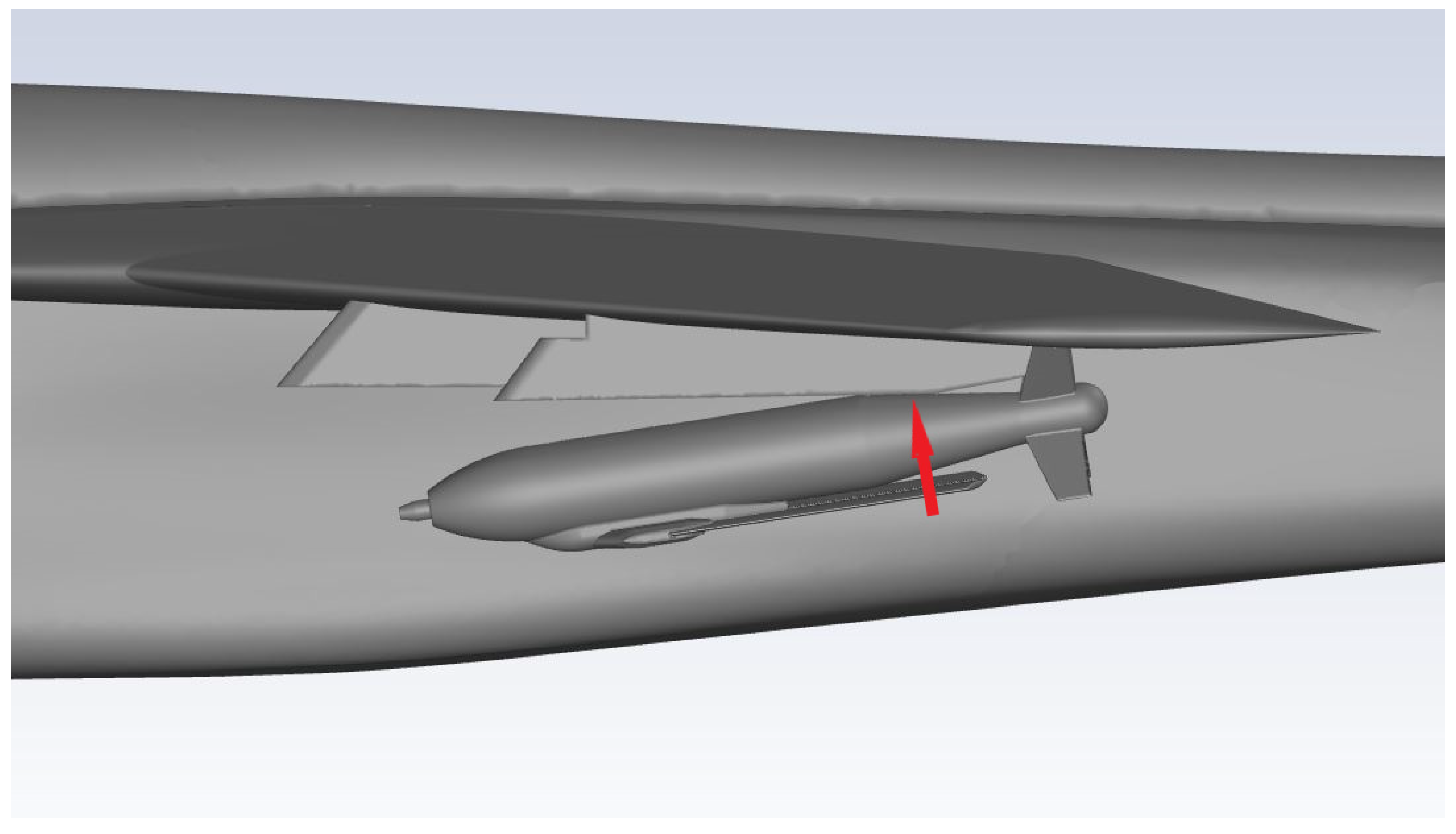
The numerical analysis of store separation requires a geometrically accurate representation of both the aircraft and the external store, because even small discrepancies in shape or relative position can alter the aerodynamic interactions that govern the early stages of release. In this study, realistic geometries are considered. The external store is a guided bomb whose geometry includes a glide kit with the wings and tail assembly consisting of surfaces responsible for providing aerodynamic stability after release (Figure 1), whereas the carrier is a jet aircraft with a high-wing configuration and a negative dihedral angle. Such a configuration leads to strong aerodynamic interference in the wing–store flow field, which significantly affects the store separation process. The guided bomb used in this study has a total mass of 290 kg. Its center of gravity, expressed in the bomb-fixed coordinate system with the origin at the nose, is located at x = 773 mm, y = −18.3 mm, and z = 0 mm. The inertial characteristics of the store are defined by a roll moment of inertia of 5 kgm2 about the longitudinal axis, a pitch moment of inertia of 65 kgm2 about the lateral axis, and a yaw moment of inertia of 66 kgm2 about the vertical axis. The remaining components of the inertia tensor are less than 0.5 kgm2 and can be considered negligible. These values describe the store’s resistance to rotational acceleration during release and are used directly by the 6DOF solver to predict its motion.
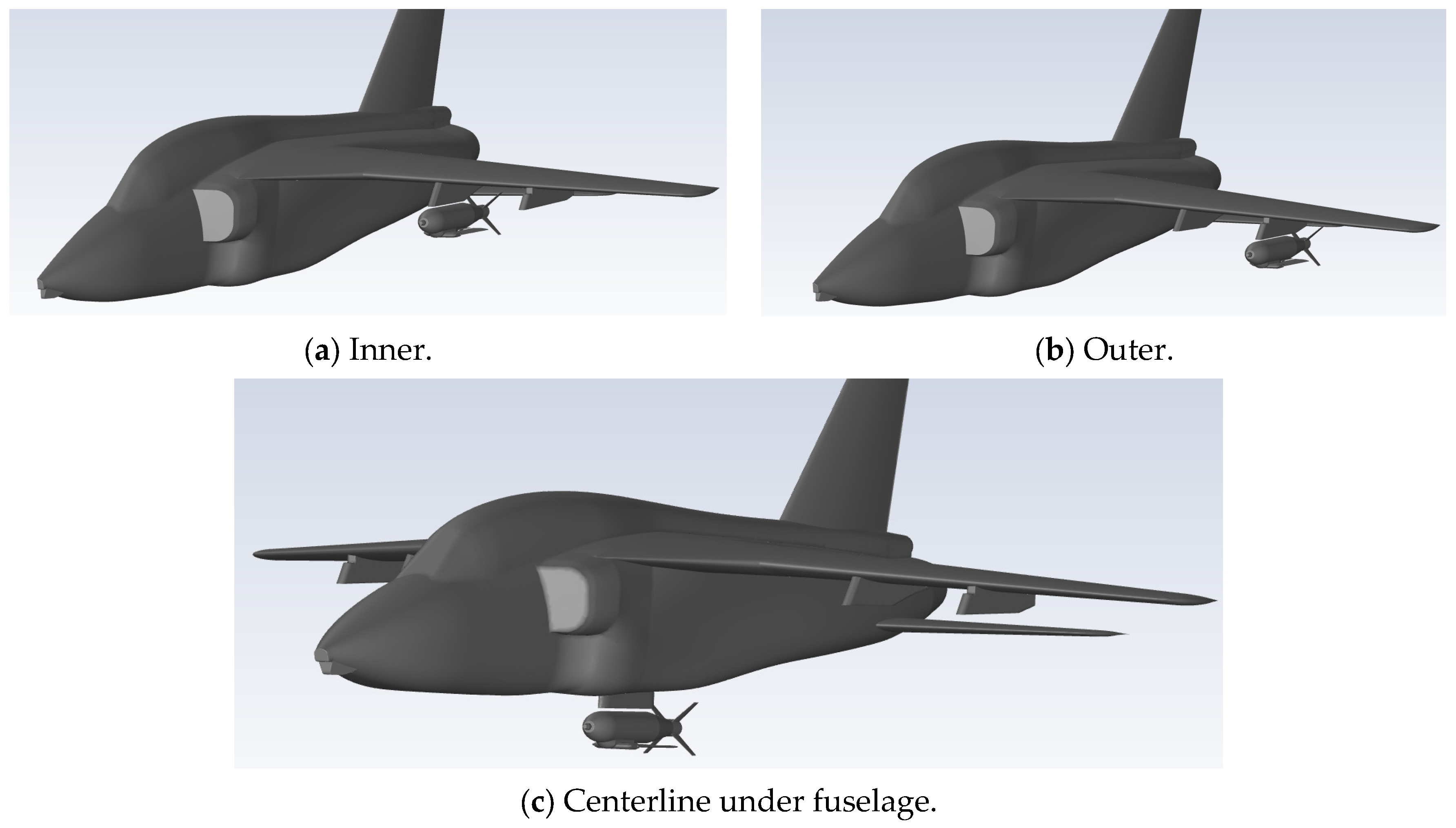
The position of the external store relative to the aircraft plays a critical role in determining the aerodynamic forces and moments acting on the external store at the moment of the release. These coordinates define the precise initial position of the store in each configuration and form the reference point from which the separation trajectory begins (Figure 2). To reduce computational cost while maintaining physical accuracy, only half of the aircraft is used in cases where the store is mounted beneath a wing, since it is symmetric with respect to the central longitudinal plane. On the other hand, it cannot be used for the fuselage centerline configuration. Because the store’s trajectory is governed by the full 6DOF equations, it is necessary to use the complete 3D model without symmetry constraints. Any symmetry boundary condition would artificially constrain lateral or rotational motion and enforce a mirrored flow field, which can lead to incorrect predictions of aerodynamic forces, moments and finally the separation trajectory.
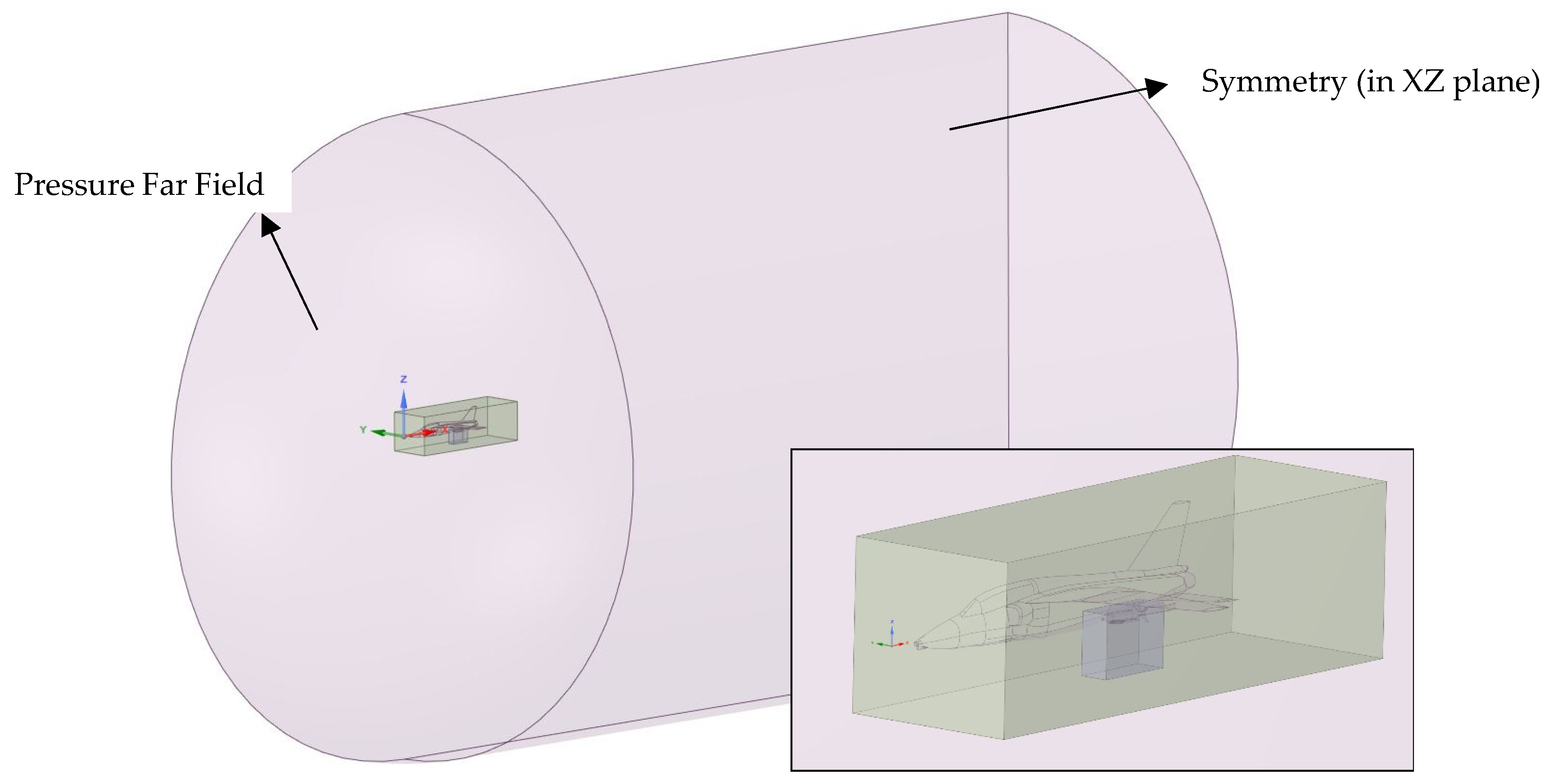
A computational domain was constructed around the combined aircraft–store configuration, extending eight aircraft lengths downstream and four aircraft lengths upstream and laterally from the numerical model. These dimensions create a large enough region in which the flow can develop without interference with boundary conditions [43]. Two subdomains are created in the main volume to help with the mesh refinement (Figure 3). The first surrounds the aircraft itself. The second surrounds the store and the region immediately beneath it, since this is where the most significant aerodynamic interactions occur during the initial phase of the release. The use of these local refinement zones ensures that the mesh can be selectively concentrated where gradients in pressure and velocity are the greatest, while the remainder of the domain can be meshed more coarsely to reduce computational time.
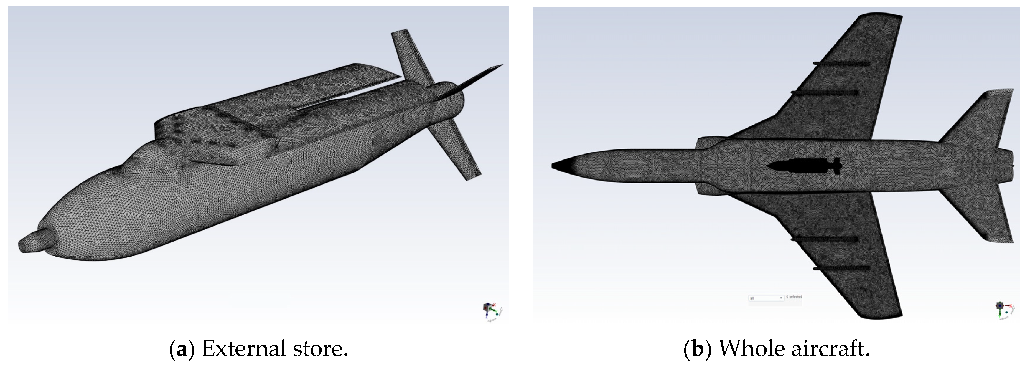
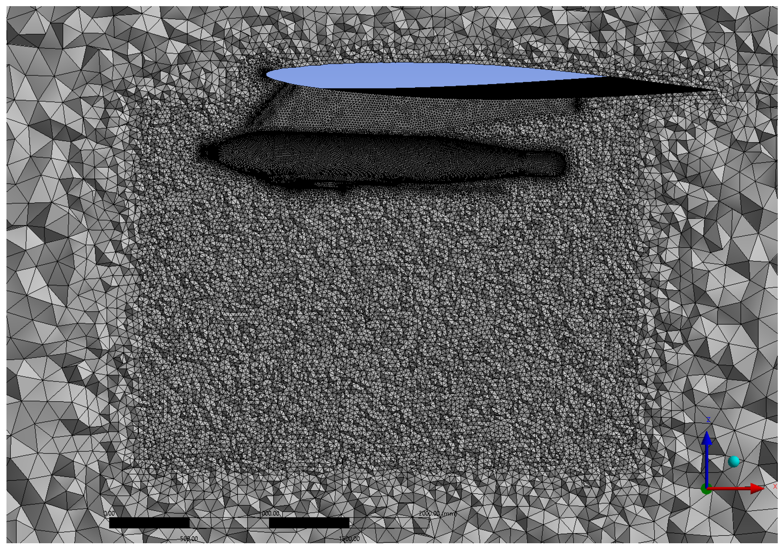
The computational domain was discretized using an unstructured tetrahedral mesh capable of accurately reproducing the complex geometry of both the aircraft and the external store [44,45] with an average skewness of approximately 0.22. The inflation layers were not employed because, when combined with the remeshing method adopted in this study, they can lead to poor-quality cells during the remeshing process and may lead to divergence. To try to compensate for his deficiency, the surface mesh was additionally refined to improve the near-wall resolution (Figure 4) and the value of dimensionless wall distance y+ was above 30 in all simulations.
This type of mesh was selected because it conforms well to highly curved aerodynamic surfaces and allows localized refinement in regions where strong pressure gradients and unsteady flow features are expected [46]. The mesh density was increased around the aircraft and particularly beneath the store, since the accuracy of the predicted separation behavior depends strongly on the resolution of the flow field in the region through which the external store travels immediately after release (Figure 5). Local refinement was implemented that imposes smaller cell sizes in critical zones while permitting a coarser grid in the outer parts of the domain. When the geometry allowed the use of a symmetry plane, the resulting mesh consisted of approximately 8.3 million elements, whereas the full model required for the fuselage centerline configuration contained roughly 14 million elements.
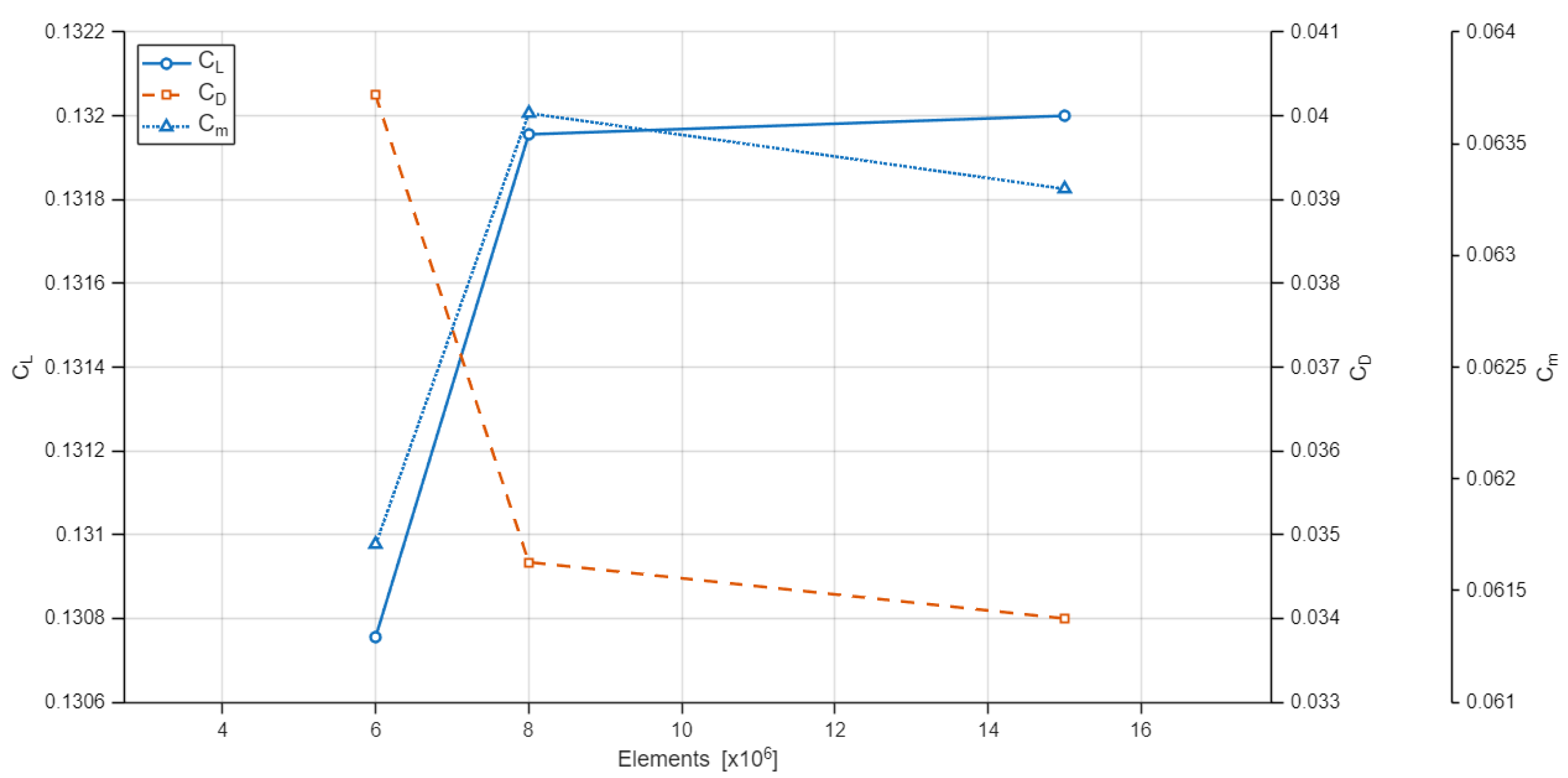
A mesh study was performed using three mesh densities of approximately 6 million, 8 million, and 15 million elements. The aerodynamic coefficients of aircraft and store combined were evaluated, and only minor differences were noticed between the 8 million and 15 million element meshes (Figure 6). Therefore, the mesh with 8 million elements was selected for the remainder of the study.

3. Numerical Set-Up

Transient numerical simulations were performed in ANSYS Fluent (2022 R1) [47], where the governing flow equations were solved by the finite volume method. The simulation is performed using a density-based solver, since the relevant flight conditions lie in the transonic regime where compressibility effects cannot be neglected. In this formulation, density is obtained from the continuity equation, while pressure is derived through the equation of state. The governing equations for mass, momentum, and energy are solved in their compressible Navier–Stokes form using a finite-volume discretization. The conservation of mass is expressed as follows:
ρ t +       ρ u     =   0 ,
and the conservation of momentum is expressed as follows:
( ρ u ) t   +   ( ρ u u )   =   p +   τ ,
where ρ is density, u is velocity, p is pressure, and τ is the viscous stress tensor. The energy equation governs the transport of internal and kinetic energy and is included to ensure accurate representation of compressible aerodynamic phenomena. Pressure is related to density and temperature through the ideal-gas equation of state:
p   =   ρ R T
Far-field boundary conditions specifying the value of Mach number, angle-of-attack, total pressure po = 54,019.9 Pa and total temperature To = 255.65 K (corresponding to the flight altitude of h = 5000 m) were defined along the outer boundaries, whereas a symmetry condition was assumed in the symmetry plane (when needed). The walls of both the store and the carrier are assumed to be no-slip. The two equation Shear Stress Transport k–ω turbulence model is selected for the closure of the momentum equation. No additional correction terms are introduced into the turbulence model formulation, enabling the same modeling approach to be applied to other geometries and allowing direct comparison with the present results. The convective fluxes are evaluated using the Roe flux scheme. This steady solution is used as the initial condition for the subsequent unsteady simulation that models store separation. The unsteady analysis uses a first-order implicit temporal discretization to maintain numerical stability during the rapid and highly nonlinear motion that follows store release. Several time-step sizes were examined, and Δt = 0.001 s was identified as the optimal choice, as it provides stable convergence while preserving the accuracy required to capture the relevant store positions during separation. At each increment of time, the solver computes the aerodynamic forces and moments acting on the store and couples them to a 6DOF rigid-body motion model. These determine the instantaneous position and orientation of the store, which are then fed back into the flow solver for the next time step.
The motion of the store requires continuous deformation of the surrounding mesh, and this is achieved using the dynamic mesh. The mesh adapts to store displacement using spring-based smoothing for small motions, allowing elements to stretch or compress while retaining a valid shape. When local deformation exceeds allowable limits, an automatic remeshing algorithm regenerates mesh regions to maintain proper cell quality and prevent the formation of negative volumes. This combination of smoothing and remeshing ensures numerical stability throughout the entire release process. Although overset mesh methods are widely used for moving-body problems, the dynamic mesh method was adopted in the present study because of the extremely small initial clearance between the store and the wing, combined with the compressible near-transonic flow regime, making the overset interface particularly sensitive to donor cell deficiency, orphan cell formation, and interpolation errors in regions of strong flow gradients. Under such conditions, the dynamic mesh approach was considered more convenient option for maintaining solution stability.
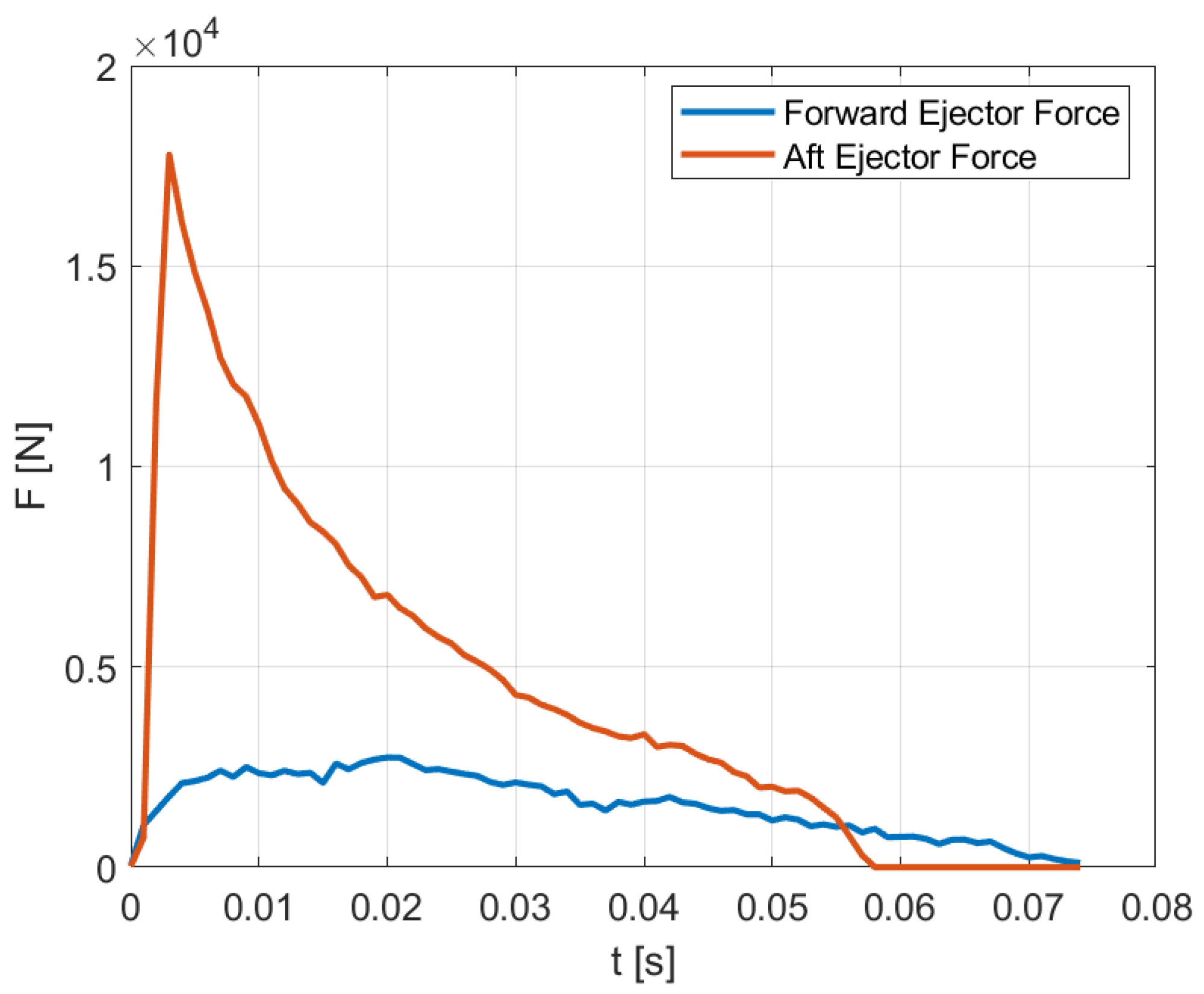
To reproduce this ejection mechanism in the numerical simulation, the impulse forces must be transferred from their physical application points to the store’s center of gravity, because the 6DOF solver in ANSYS Fluent accepts external loads only when they are applied at this location [47]. The experimental force–time diagrams, shown in Figure 7, for the chosen ejector configuration are used to define the magnitudes of the forward and aft impulses. To correctly model their influence, each force is translated to the center of gravity with associated moment generated by the offset distance between the ejector and the center of gravity of a store. The combination of these transformed forces and moments generates the same initial motion that would occur in real flight.
The implementation of these forces within the simulation is achieved through a User-Defined Function written in C and compiled in ANSYS Fluent [47]. These functions read the simulation time and return the instantaneous values of the ejector loads based on curve-fitted representations of the experimental diagrams. The time resolution of the UDF corresponds to the simulation time step, which is set to Δt = 0.001 s to allow accurate reproduction of the short impulse peaks. When the impulse period ends, the UDF automatically returns zero force and zero moment, allowing the store’s motion to evolve solely under the influence of gravity and aerodynamic loads.

4. Results and Discussion

4.1. Comparison to a Simpler 3DOF Model

Prior to the detailed analysis of the numerical results obtained by the more developed 6DOF model described in the previous section that takes into account the complex aerodynamic effects, simpler computations of the 3DOF flight paths were also performed where the trajectories of the external store are considered only in the longitudinal xz-plane [48]. The symmetric motion of the rigid body in body-fixed coordinate system is modeled by the following equations:
M   =   C m q S l   =   I y   θ ¨ ,
F n = C L q S W cos γ   = m a n = m V γ ˙ ,
F t =   C D q S W   sin γ = m a t = m V ˙ ,
α = θ γ     α ˙ = θ ˙ γ ˙ ,   α ¨ = θ ¨ γ ¨ ,
where CL, CD and Cm denote lift, drag and pitching moment coefficients of the store respectively, while q is dynamic pressure, S and l are its reference area and length, m and Iy are model’s mass and moment of inertia, W is model’s weight and the unknown variables are as follows: velocity magnitude V, model’s orientation in space θ, path angle γ and angle-of-attack α. The governing equations are solved using the finite difference method, whereas the aerodynamic coefficients are approximated from the converged steady values used as a starting point for the performed subsequent dynamic FVM simulations.
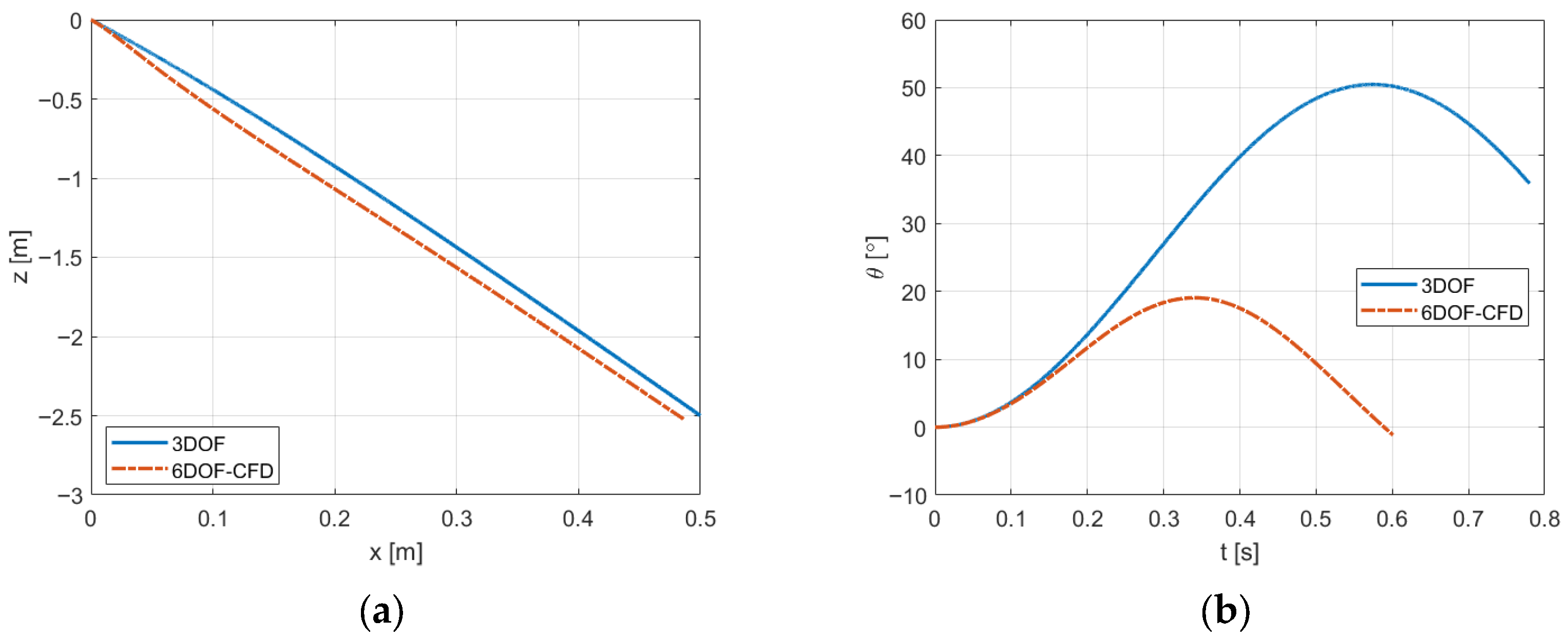
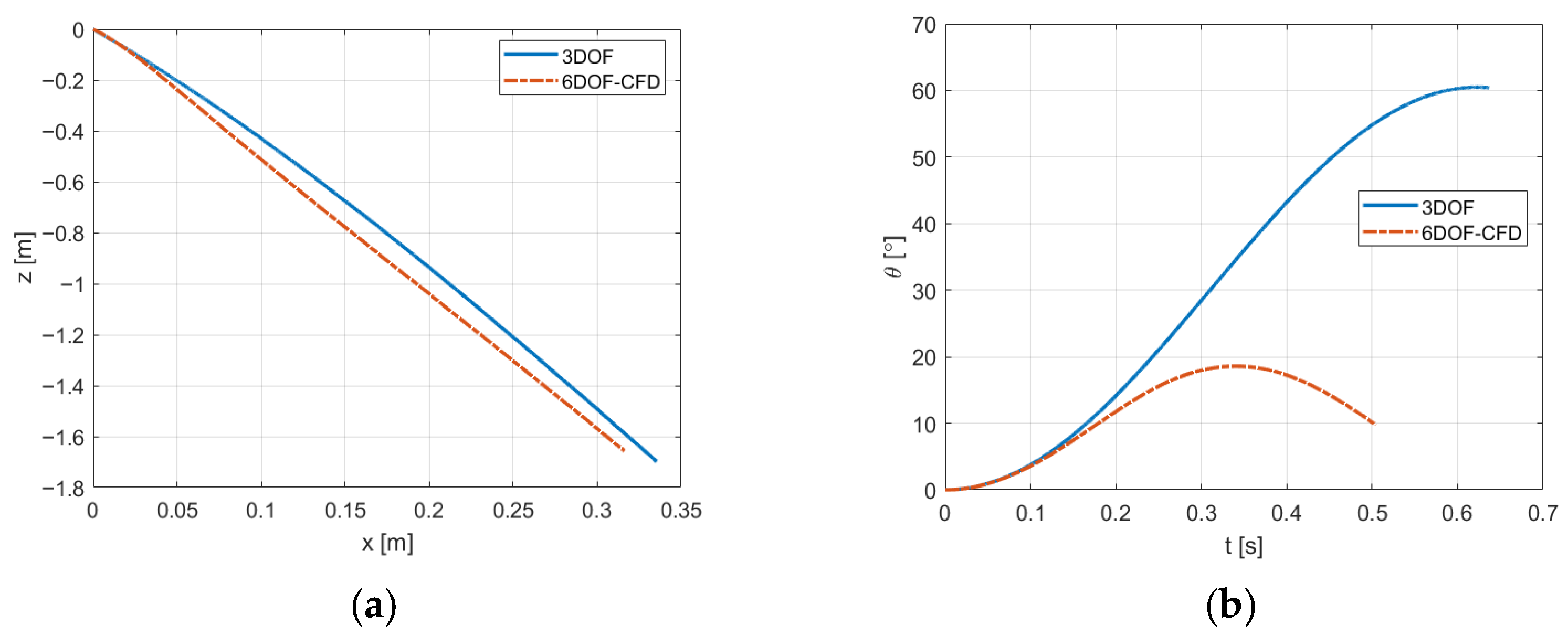
The comparison between the results of the two models is illustrated in Figure 8 and Figure 9, where separations from the outer and inner stations, respectively, are depicted. It can be seen that while the longitudinal increment is similar, there are noticeable differences in the values of orientation (although the trend of change is comparable) as well as the passed time. It can be concluded that, in reality, the store operates in a highly complex aerodynamic environment, where the carrier geometry and resulting effects cannot be neglected, which affects its lateral movement and stability. Therefore, the applicability of the simpler 3DOF model is limited, and for more reliable results, it is necessary to continue with the more developed 6DOF model combined with CFD techniques.

4.2. Gravitational Separation

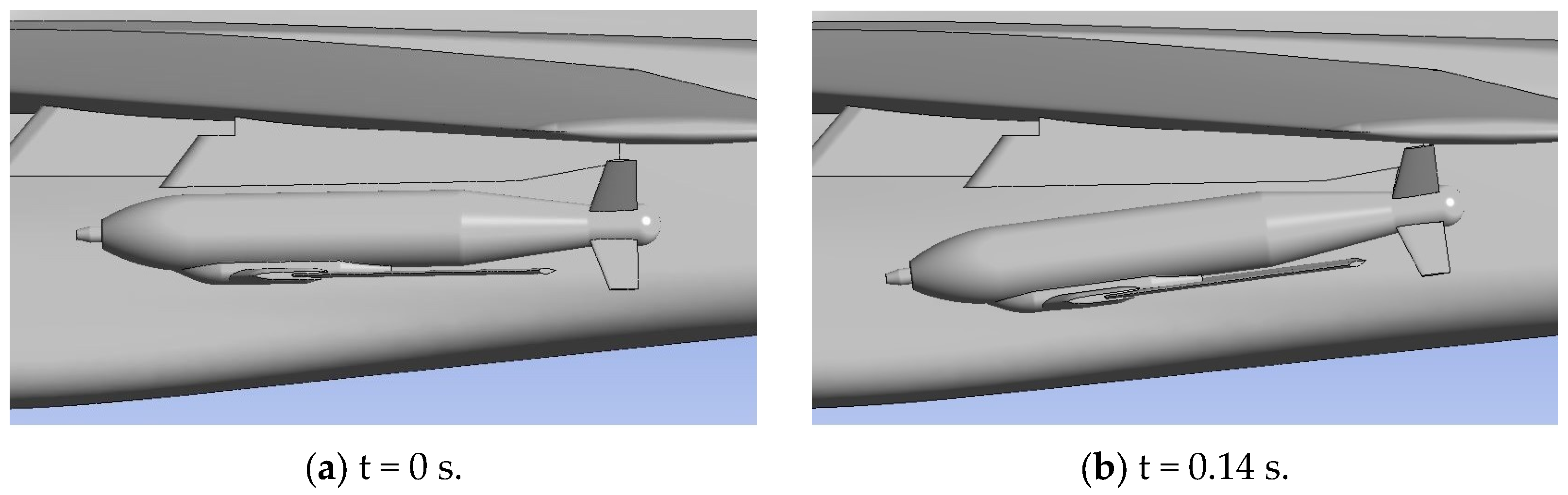
Due to the high flight velocities involved, aerodynamic forces have become strongly dominant. The first case we observe is gravitational release, which represents the less favorable scenario. Because of the location of the center of gravity and the configuration of the aerodynamic surfaces, the external store has a tendency for its tail section to pitch upward immediately after release. This behavior is critical because it reduces the lateral clearance between the store and the aircraft, limiting the time available for the store to move away safely. Figure 10 illustrates the store motion immediately after release at a flight speed of Mach 0.6. The total simulation time is 0.6 s, with a time step of 0.001 s, selected to accurately capture the transient dynamics of the separation process. The most prone component to potential impact is the tip of the store’s tail fins. At a flight speed of Mach 0.6 and under gravitational release conditions, no contact occurs between the store and the aircraft for any of the available suspension stations across the full range of angle-of-attack conditions.
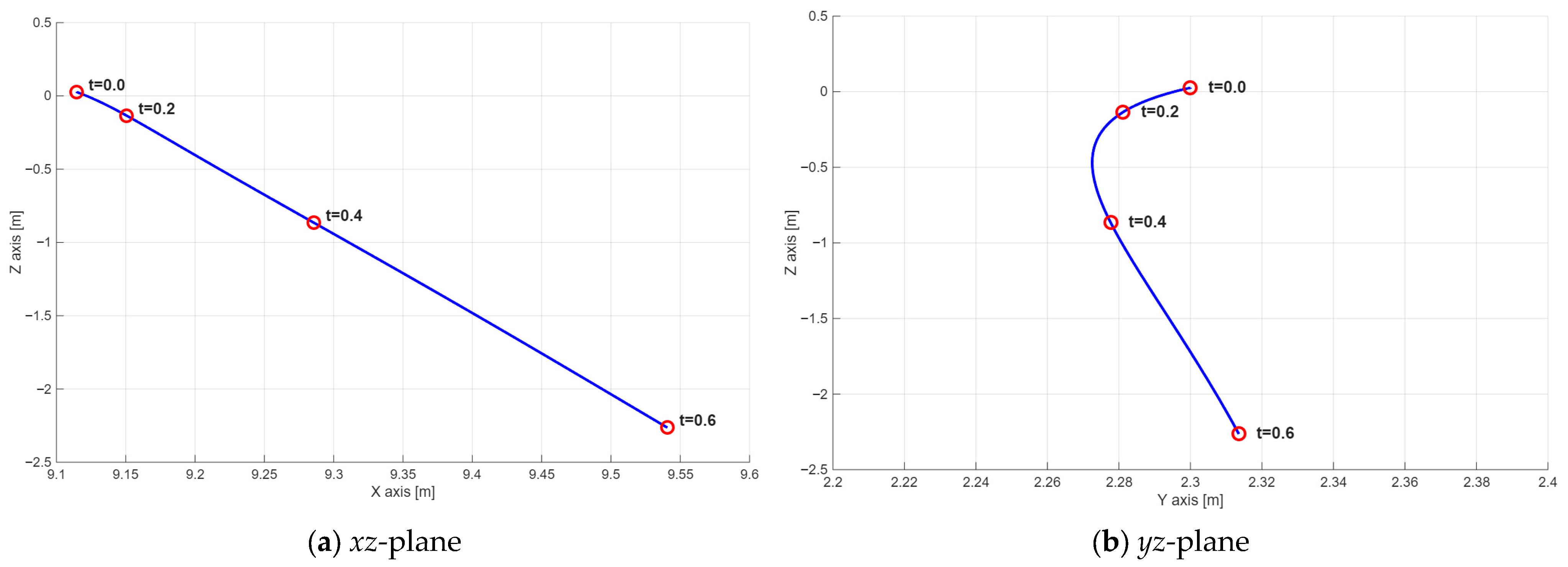
Figure 11 presents the trajectory of the store at M = 0.6 in xy- and yz-plane. In the initial phase of separation, within the first 0.2 s, the store remains close to the wing, indicating limited displacement immediately after release. During the subsequent interval, the separation distance increases, and the progressively larger displacement in the negative z direction is consistent with a growth of the vertical velocity component Vz. The xz projection demonstrates an approximately linear downstream-descending trajectory, while the yz projection indicates only a slight lateral movement, much smaller than the corresponding vertical fall. The larger spacing between consecutive time instants further suggests an increase in the store velocity as the separation progresses. At 0.6 s, the store is fully and safely separated from the aircraft.
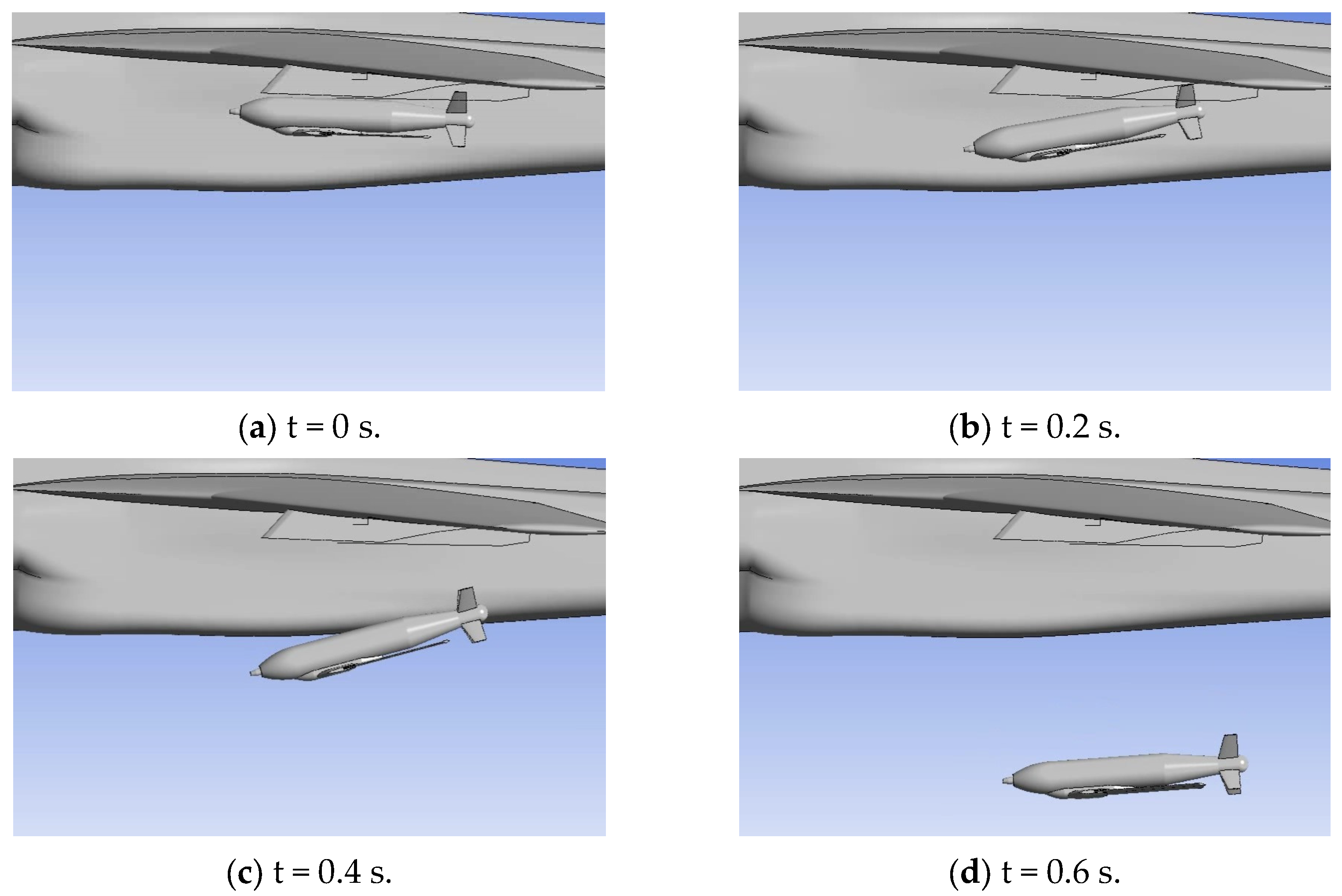
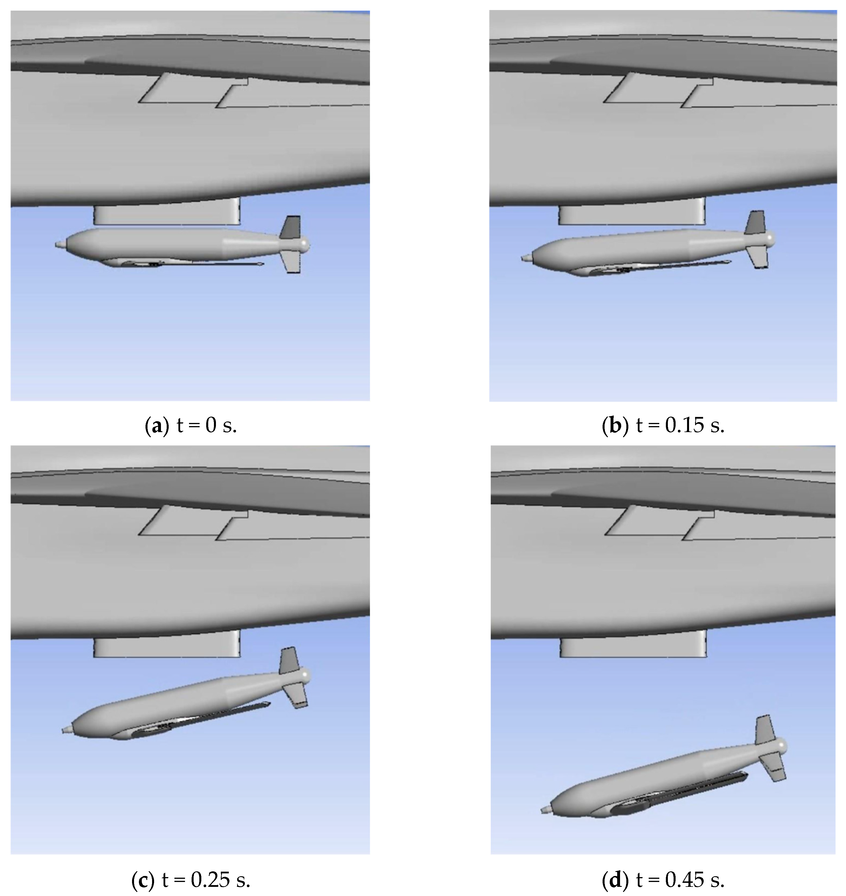
The post-release behavior of the store from the inner wing pylon and the fuselage centerline pylon is presented in Figure 12 and Figure 13, respectively. From the side-view perspective, similar pitch behavior can be observed in both cases. However, the differences associated with the varying store release positions will be discussed later in the paper.
At a flight speed of Mach 0.7, the behavior of the store during gravity-based release differs significantly from the previous case. In these simulations, any physical contact between the external store and the aircraft results in an immediate termination of the analysis, as such interaction produces negative cell volumes within the computational mesh. Nevertheless, all data up to the point of termination are retained, making it possible to determine the exact location and nature of the impact. For Mach 0.7, the simulations consistently show that contact occurs between the body of the store and the wing pylon (Figure 14). The rear section of the body strikes the underside of the wing pylon, indicating that safe separation cannot be maintained under gravity-only conditions at this speed. Table 1 and Table 2 contain records of simulated cases and their outcomes. For both pylon positions, all cases at M = 0.6 were completed successfully for the analyzed angles-of-attack, indicating safe separation under these conditions. On the other hand, at M = 0.7, collision between the store and the aircraft occurred for all considered angles-of-attack in both configurations. The collision times for M = 0.8 and M = 0.9 confirm that increasing flight speed leads to earlier impact, which is consistent with stronger aerodynamic forces acting on the store. Although a higher angle-of-attack slightly delays the collision, it does not prevent it once the flight speed reaches critical value. Based on this trend, the remaining analyses were omitted in order to reduce the computational costs.

4.3. Impulse Separation

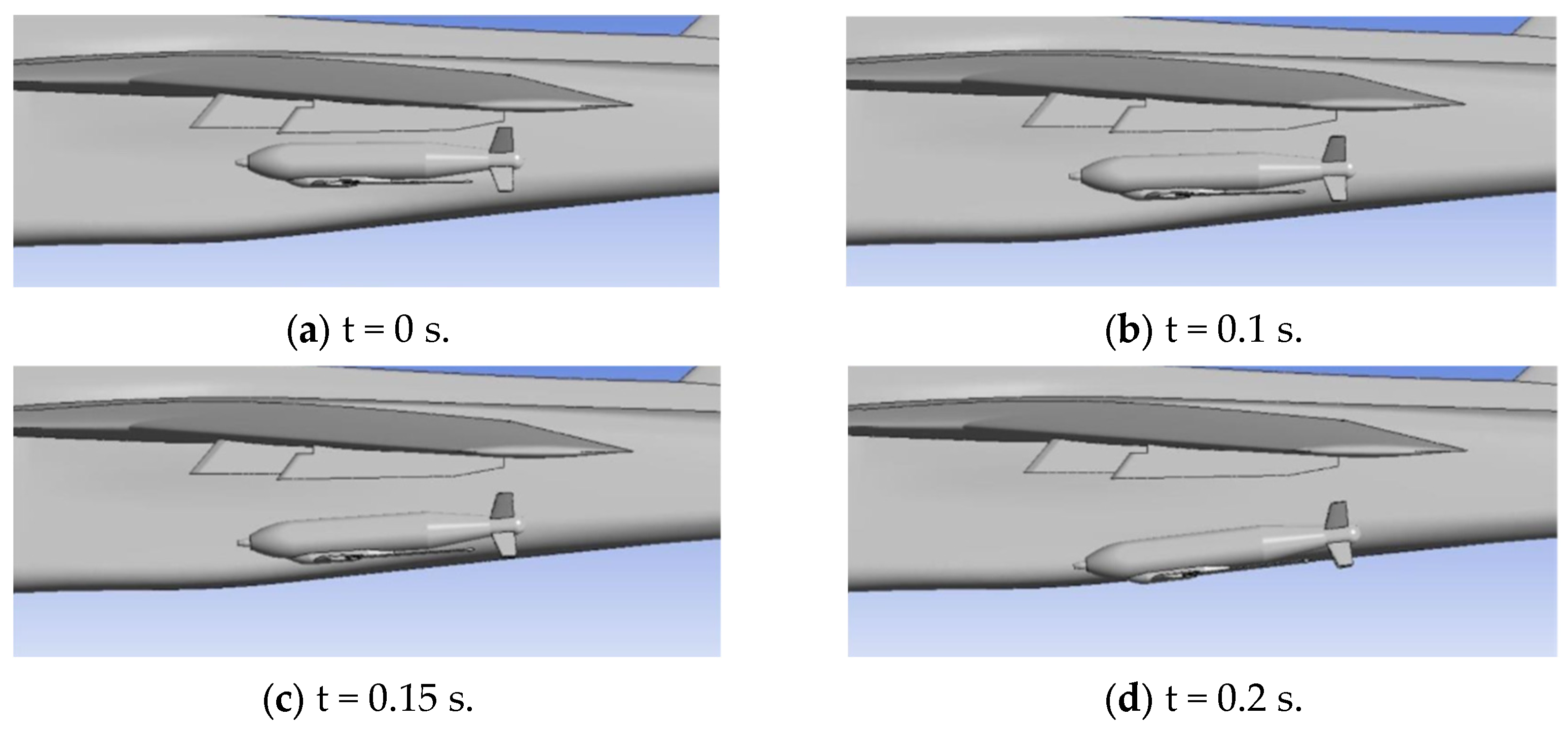
The purpose of impulse-based release is to provide the external store with an initial translational velocity and a controlled rotation about the y axis, ensuring safe separation from the aircraft and stable subsequent free flight. The analysis confirms that this objective is achieved. Figure 15 shows the uniform downward motion of the store under the action of the impulse forces at a flight speed of Mach 0.6. Once the impulse forces cease, the store again exhibits a tendency for its tail to pitch upward, but at this stage the behavior is acceptable because the store has already moved sufficiently far from the aircraft.
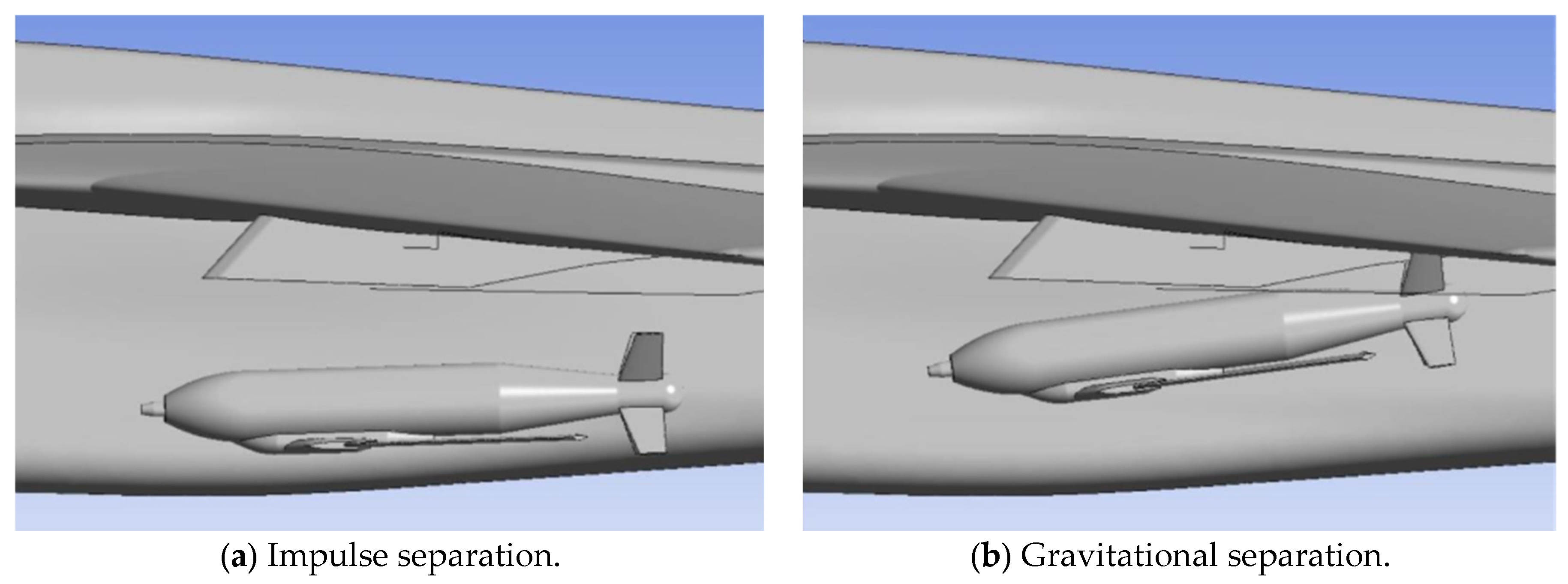
In the case of gravitational separation at a flight speed of Mach 0.7, the external store repeatedly had contact with the aircraft, whereas the situation changes considerably when impulse-based release is applied. Figure 16 illustrates the difference in store instantaneous positions for the two release methods at the same moment in time.
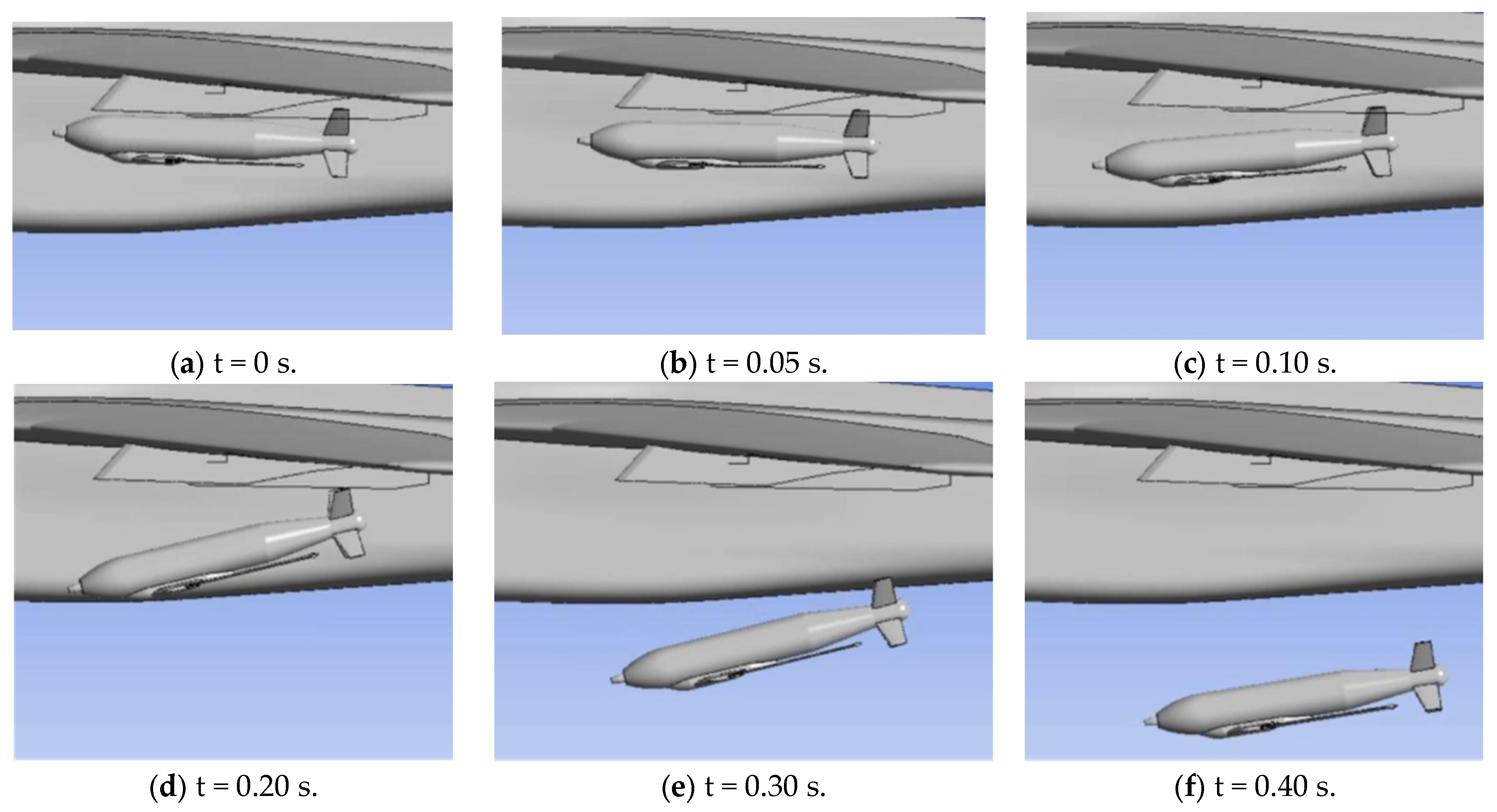
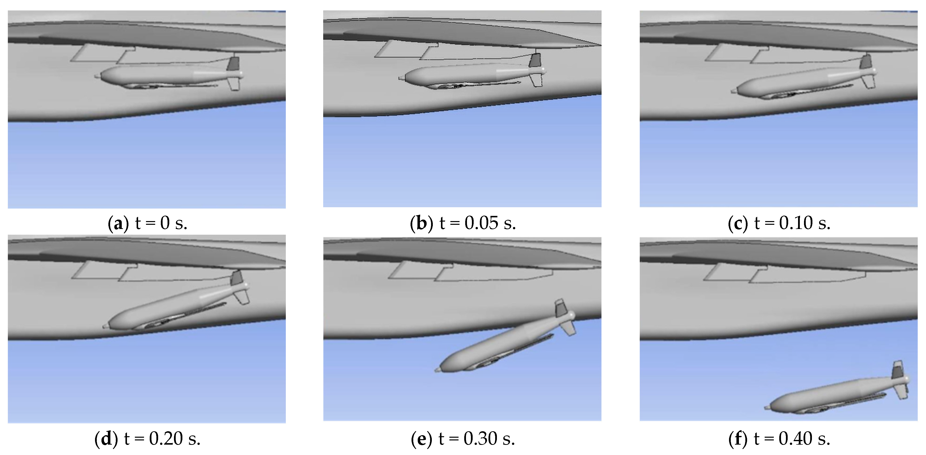
As the aircraft’s flight speed increases, the aerodynamic forces acting on the external store also become stronger, while the magnitude of the impulse force remains constant. As a result, the store’s tail moves away from the aircraft at a slower rate during the initial phase of release. Figure 17 and Figure 18 illustrate the behavior of the store under impulse-based release at Mach numbers 0.8 and 0.9, respectively. At the speed of Mach 0.9 the separation process again enters a critical regime, since the tail section of the store approaches the aircraft wing very closely despite the presence of impulse forces.
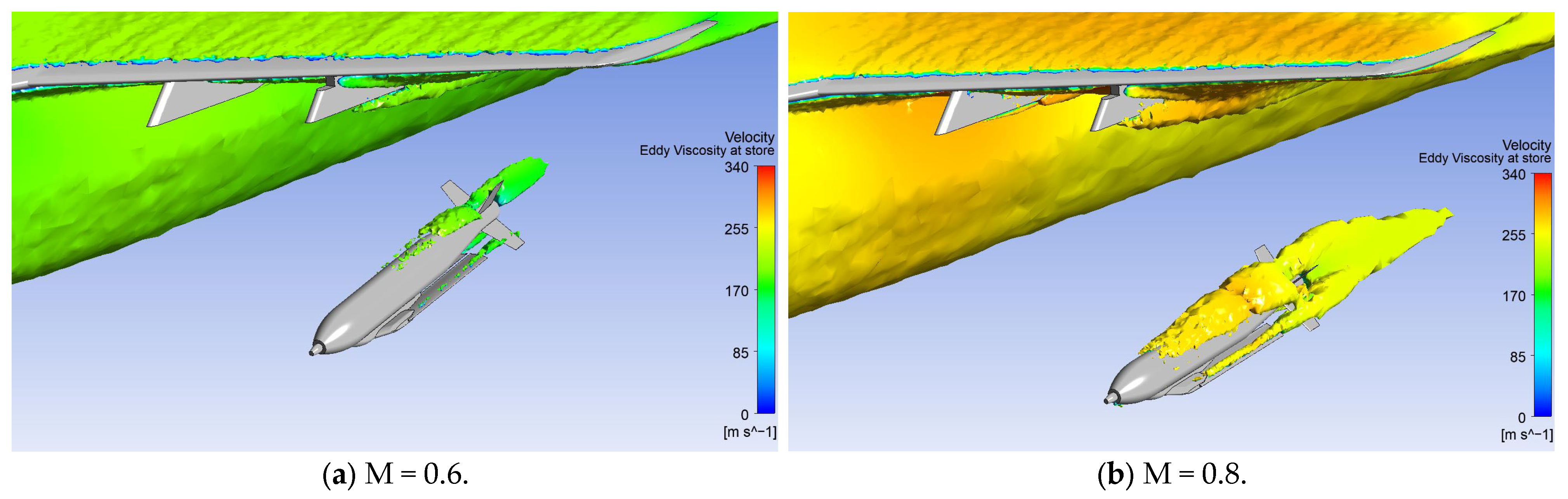
Figure 19 compares the turbulent flow structures colored by velocity around the store at the same time instant for M = 0.6 and M = 0.8. In the M = 0.6 case, the regions of elevated turbulence are relatively localized, appearing mainly over the upper aft portion of the store, while the forebody remains largely unaffected. In contrast, for M = 0.8, the turbulence field becomes much more extensive and intense, covering a larger portion of the upper surface and extending farther downstream. The thicker and more continuous turbulent region suggests stronger shear-layer development, enhanced vortex activity, and more pronounced wake formation at the higher Mach number.

4.4. Different Motions of the Store with Angle and Position Changes

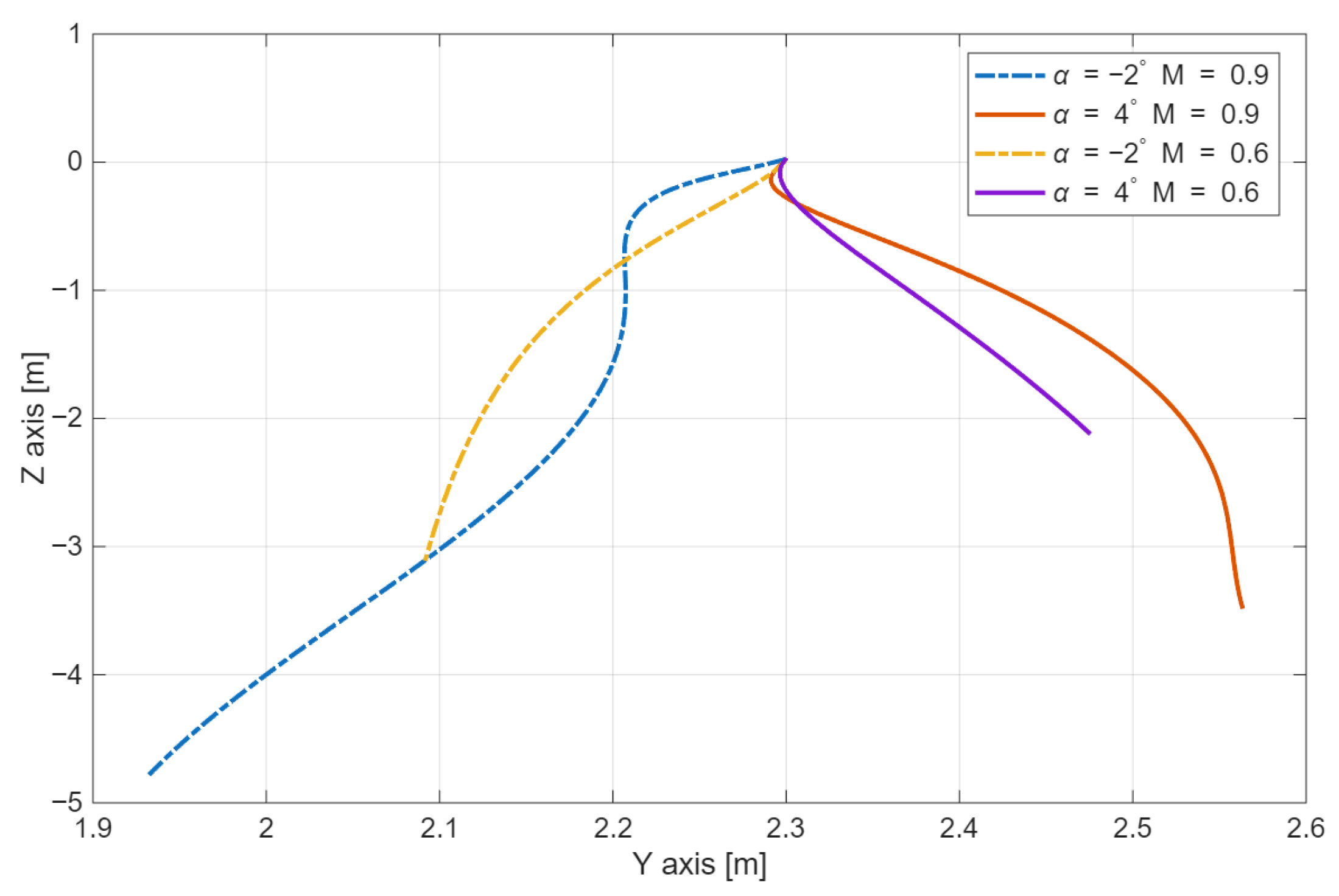
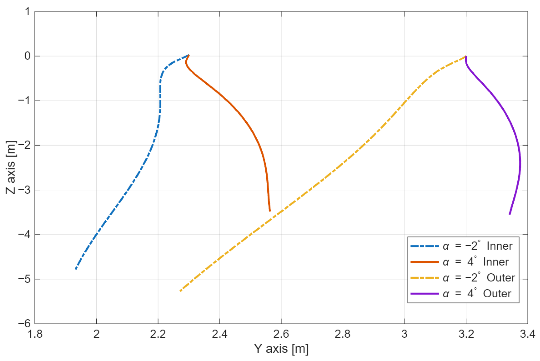
By varying the angle-of-attack throughout the analysis, different store behaviors were observed. The examined range of aircraft angles-of-attack extends from −2 degrees to 4 degrees, with increments of 2 degrees. This interval allows the assessment of external store behavior during release at both negative and positive angles-of-attack. Two distinct trends emerge from the results. At the negative angle-of-attack of −2 degrees, the store exhibits a tendency to move toward the aircraft during its descent after release, whereas at positive angles-of-attack the store consistently moves away from the aircraft. This lateral deviation of the store is not significantly influenced by aircraft speed; however, increasing flight speed amplifies the intensity of the store motion either toward or away from the aircraft. Figure 20 presents the diagram showing the influence of aircraft speed on store flight paths. The diagram indicates that the store behaves differently in the initial moments at negative angles-of-attack, although the overall tendency to move toward the aircraft remains present. Figure 21 illustrates the trajectory of the store center of gravity as a function of the suspension station from which the store is released. The results show that the stores exhibit similar lateral behavior with respect to deviation toward or away from the aircraft, regardless of the suspension station. The only noticeable difference is that the store released from the outer wing station moves slightly closer to the aircraft; however, since this station is located farther from the fuselage compared to the inner wing station, this behavior does not pose any issue during separation.
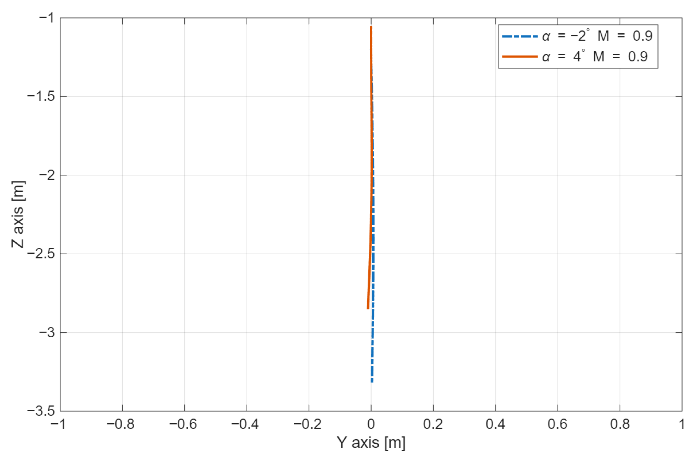
The situation is different for the centerline, where the aircraft’s angle-of-attack does not influence the lateral deviation of the store during its fall. In fact, no lateral deviation is observed at all. This behavior is illustrated in Figure 22. To more clearly demonstrate the nearly linear downward motion of the store, a wider diagram range was used, extending one meter to the left and one meter to the right of the symmetry plane. As a reference dimension, the fuselage width of the aircraft in this section is approximately 1.7 m.
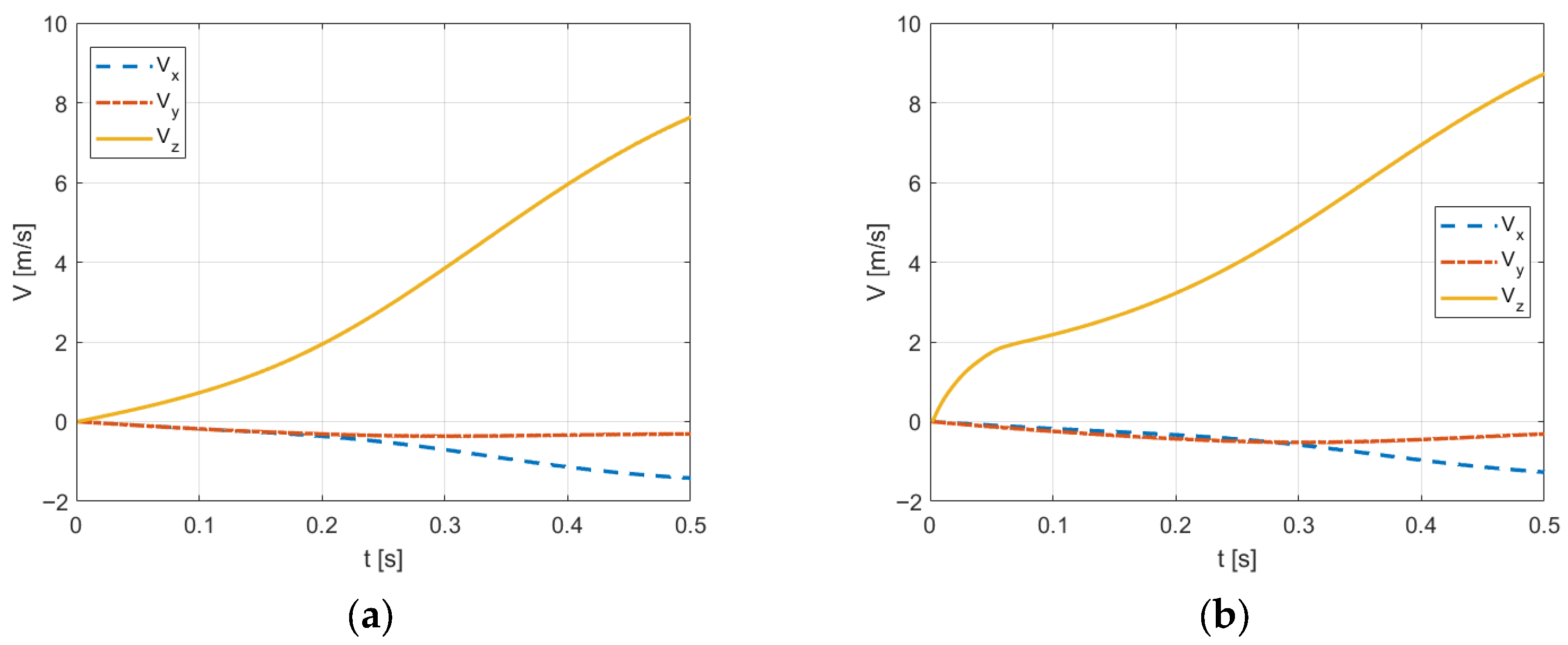
The three velocity components computed when the aircraft is flying at M = 0.6 and the store is separated from the inner section, are depicted and compared in Figure 23. On the left, the angle-of-attack is zero degrees, and on the right, the angle-of-attack is −2 degrees. It can be observed that impulse forces dominantly alter the vertical velocity component, giving it “an initial push” so that the external store can safely move away from the carrier. At this flight regime, it appears that the small difference in the angles-of-attack does not significantly influence the other two velocity components.
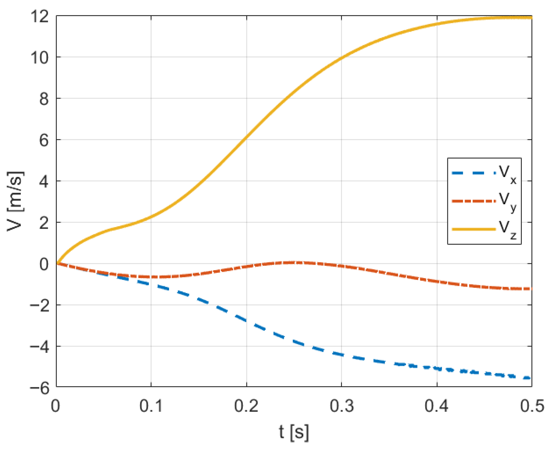
Figure 24 illustrates that the increase in the Mach number greatly affects the movement of the store away from the wing. Both the frequencies and the amplitudes of the changes in velocity components are much more pronounced. In comparison to the trendlines obtained for M = 0.6 the value of Vx nearly triples in the same period of time, while the component Vy shows an oscillatory trend.

5. Conclusions

In this research paper, we present in detail the performed complex numerical analyses of store separation under highly subsonic and transonic speeds. Geometries of both the carrier and the store are realistically modeled, and the flow is considered transient, viscous (turbulent) and compressible. The employed computational mesh comprises tetrahedral elements of sufficient resolution and quality to comply with the starting geometric models of the carrier and the store. During the computations realized using ANSYS Fluent, the mesh cells deform and regular remeshing actions are performed to accurately capture the 6DOF movements of the store. In addition, different separation scenarios (e.g., store locations, carrier speeds and angles-of-attack, as well as separation type—gravitational vs. impulse) are considered and compared.
In this work, Computational Fluid Dynamics, coupled with a dynamic mesh and six-degree-of-freedom motion modeling, provides a useful numerical tool for predicting the separation characteristics of the guided store when released from an aircraft. The analysis reveals that gravity-based release is highly sensitive to flight speed and becomes unsafe at Mach 0.7, resulting in contact between the store and the aircraft wing regardless of the angle-of-attack. Impulse ejection significantly improves the separation behavior by introducing an initial downward velocity and a stabilizing rotational motion that counteracts the natural aerodynamic pitch-up tendency of the store tail section. This approach ensures safe release at Mach numbers up to 0.8.
The obtained results further show that the aircraft angle-of-attack influences the lateral displacement of the store, with negative angles producing a tendency for the store to drift toward the aircraft and positive angles driving it away, while the fuselage centerline station remains unaffected due to less disturbed flow under the aircraft. Both qualitative and quantitative data also demonstrate that the presence and influence of the actual aircraft cannot be neglected.
This study can be further improved by choosing a more complex turbulence model and using finer meshes, but that requires more computational time and effort. Although CFD provides valuable predictions, the most reliable way to verify store-separation safety is through full-scale flight testing. Flight experiments capture real aerodynamic effects that simulations cannot fully reproduce, but they are significantly more expensive and carry higher operational risk. For that reason, they are mainly used only after performing detailed numerical analyses and obtaining results that indicate acceptable store behavior.

Author Contributions

Conceptualization, I.N. and J.S.; Methodology, I.N. and J.S.; Software, J.S.; Validation, I.N. and J.S.; Formal analysis, I.N. and J.S.; Investigation, I.N. and J.S.; Resources, I.N. and J.S.; Writing—original draft, I.N.; Writing—review & editing, J.S.; Visualization, I.N.; Supervision, J.S.; Funding acquisition, I.N. and J.S. All authors have read and agreed to the published version of the manuscript.

Funding

This work was supported by the Ministry of Science, Technological Development and Innovation, Republic of Serbia (Contract Nos. 451-03-34/2026-03/200325 and 451-03-34/2026-03/200105).

Data Availability Statement

Data is contained within the article.

Conflicts of Interest

The authors declare no conflict of interest.

Abbreviations

The following abbreviations are used in this manuscript:
CFDComputational Fluid Dynamics
DOFDegree of Freedom
UDFUser-defined function
FVMFinite Volume Method

References

  1. Cenko, A. Store separation lessons learned during the last 30 years. In Proceedings of the 27th International Congress of the Aeronautical Sciences (ICAS 2010), Nice, France, 19–24 September 2010. [Google Scholar]
  2. Cenko, A. Store Separation Overview. In Store Separation; STO-EN-SCI-277; NATO Science and Technology Organization: Neuilly-sur-Seine, France, 2018; pp. 4-1–4-16. [Google Scholar]
  3. Cenko, A.; Lee, J.; Hallberg, E. A Collaborative International Approach to Store Separation. ITEA J. 2009, 30, 126–133. [Google Scholar]
  4. Xue, F.; Qin, H.; Wang, Y.; Jiang, Z.; Jin, X.; Bai, P. Free flight wind tunnel test similarity law derivation for light store separation from aircraft. Adv. Mech. Eng. 2019, 11, 1687814019853062. [Google Scholar] [CrossRef]
  5. Seo, K.; Lee, D.-K.; Kim, S.C.; Choi, E.H.; Han, S.H.; Lee, J.G. Development of the Store Separation Test Equipment and Grid Test in the Transonic Wind Tunnel. J. Korean Soc. Aeronaut. Space Sci. 2023, 51, 669–675. [Google Scholar] [CrossRef]
  6. Heim, E.R. CFD Wing/Pylon/Finned Store Mutual Interference Wind Tunnel Experiment; AEDC-TSR-91-P4; Arnold Engineering Development Center: Arnold AFB, TN, USA, 1991. [Google Scholar]
  7. Carman, J.B., Jr.; Hill, D.W., Jr.; Christopher, J.P. Store Separation Testing Techniques at the Arnold Engineering Development Center, Volume II: Description of Captive Trajectory Store Separation Testing in the Aerodynamic Wind Tunnel (4T); AEDC-TR-79-1; Arnold Engineering Development Center: Arnold AFB, TN, USA, 1980. [Google Scholar]
  8. Demir, G. Computational Fluid Dynamics Modelling of Store Separation Using Grid Method. Master’s Thesis, Middle East Technical University, Ankara, Turkey, 2017. [Google Scholar]
  9. Rico Álvarez, J.I. Transonic CFD Analysis of an External Store Carried on a Military Aircraft Wing. Master’s Thesis, Universidad de Sevilla, Sevilla, Spain, 2022. [Google Scholar]
  10. Sunay, Y.E.; Gülay, E.; Akgül, A. Numerical Simulations of Store Separation Trajectories Using the EGLIN Test. Sci. Tech. Rev. 2013, 63, 10–16. [Google Scholar]
  11. Cenko, A.; Niewoehner, R.; Ryckebusch, C. Evaluation of CFD Capabilities for Store Separation. In Proceedings of the 40th AIAA Aerospace Sciences Meeting & Exhibit, Reno, NV, USA, 14–17 January 2002. AIAA Paper 2002-0283. [Google Scholar]
  12. Nadar, O. Aircraft/Stores Compatibility, Integration and Separation Testing; STO-AG-300-V29; North Atlantic Treaty Organization Science and Technology Organization: Neuilly-sur-Seine, France, 2014. [Google Scholar]
  13. Türk, S.; Güleren, K.M. Numerical analysis of the impact of release timing on trajectory in internal store separation. Aeronaut. J. 2025, 129, 1361–1380. [Google Scholar] [CrossRef]
  14. Johnson, R.; Davis, M.B.; Finley, D. Relaxed Fidelity CFD Methods Applied to Store Separation Problems. In Proceedings of the RTO AVT Symposium on Functional and Mechanical Integration of Weapons and Land and Air Vehicles, Williamsburg, VA, USA, 7–9 June 2004. RTO-MP-AVT-108. [Google Scholar]
  15. Olejnik, A.; Dziubiński, A.; Kiszkowiak, Ł. Separation safety analysis using CFD simulation and remeshing. Aerosp. Sci. Technol. 2020, 106, 106190. [Google Scholar] [CrossRef]
  16. Cui, P.; Zhou, G.; Zhang, Y.; Jia, H.; Wu, X.; Ma, M.; Li, H.; Chen, B. Improved Delayed Detached-Eddy Investigations on the Flow Control of the Leading-Edge Flat Spoiler of the Cavity in the Low-Aspect-Ratio Aircraft. Aerospace 2022, 9, 526. [Google Scholar] [CrossRef]
  17. Ben-Gida, H. Detached Eddy Simulations of Cavity-Store Interactions at Subsonic Turbulent Flow. Aerospace 2023, 10, 935. [Google Scholar] [CrossRef]
  18. Ding, M.; Zhao, P.; Bie, D.; Li, D.; Binienda, W.K. Trajectory reconstruction of a wingtip segment separated from an aircraft using CFD simulation. Aerosp. Sci. Technol. 2023, 142, 108678. [Google Scholar] [CrossRef]
  19. Dehghan, M.; Davari, A.R.; Dehghan Manshadi, M. Numerical investigation on the weight, speed, and installation location effects on fuel tank separation trajectory. Proc. Inst. Mech. Eng. Part G J. Aerosp. Eng. 2017, 231, 2331–2344. [Google Scholar] [CrossRef]
  20. Kozak, M.T.; Yildiz, E.N.; Yazicioglu, Y.; Cigeroglu, E. Modeling of aircraft effects on external store ejection. Proc. Inst. Mech. Eng. Part G J. Aerosp. Eng. 2019, 233, 3612–3626. [Google Scholar] [CrossRef]
  21. Fatima, K.; Ahmed, S.; Irfan, M.; Khan, H.N.; Masud, J.; Shahzad, A.; Akram, F.; Safdar, M.M. The Effects of Flight and Ejection parameters on Store Separation. In Proceedings of the AIAA SCITECH 2026 Forum, AIAA 2026-2470, Orlando, FL, USA, 12–16 January 2026. [Google Scholar] [CrossRef]
  22. Dennison, H.J.; Huebsch, W.; Griffin, C. Utilizing CFD Coupled 6DOF to Study Separation Induced Tumbling of a Missile Bus Geometry. In Proceedings of the AIAA SCITECH 2026 Forum, AIAA 2026-0241, Orlando, FL, USA, 12–16 January 2026. [Google Scholar] [CrossRef]
  23. Wang, W.; Yan, C.; Wang, S.; Huang, Y.; Yuan, W. An efficient, robust and automatic overlapping grid assembly approach for partitioned multi-block structured grids. Proc. Inst. Mech. Eng. Part G J. Aerosp. Eng. 2019, 233, 1217–1236. [Google Scholar] [CrossRef]
  24. Xuan, C.; Han, J. Improvements on overlapping unstructured grids. Proc. Inst. Mech. Eng. Part G J. Aerosp. Eng. 2020, 234, 522–534. [Google Scholar] [CrossRef]
  25. Capel-Jorquera, J.; González, L.M.; Valero, E.; Torres-Ruiz, L.; Lacruz-Alcaraz, R.; Gómez-Blanco, R. Deployable fins effect on store separation dynamics. Aerosp. Sci. Technol. 2026, 170, 111558. [Google Scholar] [CrossRef]
  26. Wang, Y.; Wu, J.; Wang, S.; Li, D.; Wang, Y.; Cao, J. Dynamic Response Analysis of Deep-Sea Mining Vehicle Modular Drop Segments during the Separation Process. J. Mar. Sci. Eng. 2024, 12, 608. [Google Scholar] [CrossRef]
  27. Jafari, M.; Toloei, A.; Ghasemlu, S.; Parhizkar, H. Simulation of Store Separation using Low-cost CFD with Dynamic Meshing. Int. J. Eng. Trans. B Appl. 2014, 27, 775–784. [Google Scholar]
  28. Zhang, B.; Feng, Z.; Yang, T.; Xu, B.; Sun, X. Integrated improvement of the elasticity-based mesh deformation method based on robust parameters and mesh quality. Proc. Inst. Mech. Eng. Part G J. Aerosp. Eng. 2019, 233, 3078–3095. [Google Scholar] [CrossRef]
  29. Lasek, M.; Sibilski, K. Modelling of External Store Separation. In Proceedings of the 40th AIAA Aerospace Sciences Meeting & Exhibit, Reno, NV, USA, 14–17 January 2002. AIAA Paper 2002-0687. [Google Scholar]
  30. Riboli, F.M. Store Separation Predictions for Weapon Integration on a Fighter-Type Aircraft. In Proceedings of the 2020 IEEE International Workshop on Metrology for AeroSpace (MetroAeroSpace), Pisa, Italy, 22–24 June 2020; pp. 1–6. [Google Scholar]
  31. Demir, H.Ö.; Selimhocaoğlu, B.T.; Demir, G.; Alemdaroğlu, N. CFD Applications in Store Separation. In Store Separation; STO-EN-SCI-277; NATO Science and Technology Organization: Neuilly-sur-Seine, France, 2018; pp. 5-1–5-30. [Google Scholar]
  32. Westmoreland, S. A Comparison of Inviscid and Viscous Approaches for Store Separations. In Proceedings of the 20th AIAA Applied Aerodynamics Conference, St. Louis, MO, USA, 24–26 June 2002. AIAA Paper 2002-1413. [Google Scholar]
  33. Purdon, M.L.; Hetreed, C.F.; Hudson, M.L. F-35 Pre-Flight Store Separation Analyses: Innovative Techniques for Affordability. In Proceedings of the 47th AIAA Aerospace Sciences Meeting including the New Horizons Forum and Aerospace Exposition, Orlando, FL, USA, 5–8 January 2009. AIAA Paper 2009-102. [Google Scholar]
  34. Tomaro, R.F.; Witzeman, F.C.; Strang, W.Z. A Solution on the F-18C for Store Separation Simulation using COBALT. In Proceedings of the 37th AIAA Aerospace Sciences Meeting and Exhibit, Reno, NV, USA, 11–14 January 1999. AIAA Paper 99-0122. [Google Scholar]
  35. Osman, A.A.; Bayoumy, A.M.; Abdellatif, O.E.; Khallil, E.E. Numerical Analysis of an External Store Separation from an Airplane. In Proceedings of the AIAA SciTech, San Diego, CA, USA, 4–8 January 2016. [Google Scholar]
  36. Persson, I.; Lindberg, A. Transonic Store Separation Studies on the SAAB GRIPEN Aircraft Using Computational Aerodynamics. In Proceedings of the 26th International Congress of the Aeronautical Sciences (ICAS 2008), Anchorage, AK, USA, 14–19 September 2008. [Google Scholar]
  37. Abuhanieh, S.; Akay, H.U.; Bicer, B. A new strategy for solving store separation problems using OpenFOAM. Proc. Inst. Mech. Eng. Part G J. Aerosp. Eng. 2022, 236, 3152–3166. [Google Scholar] [CrossRef]
  38. Abuhanieh, S.; Akay, H.U. Numerical investigation of store separation from cavity problems at high speeds. Proc. Inst. Mech. Eng. Part G J. Aerosp. Eng. 2023, 237, 3666–3680. [Google Scholar] [CrossRef]
  39. Abuhanieh, S.; Batan, B.; Aksoy, O.M.; Karaarslan, I.; Yigit, S. Parallel performance comparison of different CFD solvers and overset libraries for store separation analyses. Int. J. High Perform. Comput. Appl. 2026, 40, 158–173. [Google Scholar] [CrossRef]
  40. Peters, N.; Wissink, A.; Ekaterinaris, J. Machine learning-based surrogate modeling approaches for fixed-wing store separation. Aerosp. Sci. Technol. 2023, 133, 108150. [Google Scholar] [CrossRef]
  41. Peters, N.; Wissink, A.; Ekaterinaris, J. Comparison of Data-Driven Approaches to Rotorcraft Store Separation Modeling. J. Aircr. 2024, 61, 229–244. [Google Scholar] [CrossRef]
  42. Ahn, K.; Park, J.S.; Lee, S. Analysis Method of Store Separation Trajectory in Open Cavity Using Monte Carlo Simulation. J. Korean Soc. Aeronaut. Space Sci. 2024, 52, 101–109. [Google Scholar] [CrossRef]
  43. Naveed, A.; Javed, A. Effects of variation in flow field on store separation. In Proceedings of the 2018 15th International Bhurban Conference on Applied Sciences and Technology (IBCAST), Islamabad, Pakistan, 9–13 January 2018; pp. 293–299. [Google Scholar]
  44. Panagiotopoulos, E.E.; Kyparissis, S.D. CFD Transonic Store Separation Trajectory Predictions with Comparison to Wind Tunnel Investigations. Int. J. Eng. 2010, 3, 538–553. [Google Scholar]
  45. Gong, J.; Zhou, Z.; Liu, B. Using the Unstructured Dynamic Mesh to Simulate Multi-Store Separating from Aircraft. Procedia Eng. 2011, 16, 572–580. [Google Scholar] [CrossRef][Green Version]
  46. Osman, A.A.; Bayoumy, A.M.; El Baialy, I.; Abdellatif, O.E.; Khallil, E.E. Investigation of the Effect of Grid Size on External Store Separation Trajectory using CFD. In Proceedings of the 16th International Conference on Aerospace Sciences & Aviation Technology (ASAT-16), Cairo, Egypt, 26–28 May 2015. Paper ASAT-16-019-MO. [Google Scholar]
  47. ANSYS, Inc. ANSYS Fluent Theory Guide, Release 18.1; ANSYS, Inc.: Canonsburg, PA, USA, 2017. [Google Scholar]
  48. Svorcan, J.; Baltić, M.; Peković, O.; Simonović, A. Computational Analyses of Gravitational (Free Fall) Store Separation in Different Flight Conditions. In Proceedings of the 9th International Scientific Conference on Defensive Technologies (OTEH 2020), Belgrade, Serbia, 15–16 October 2020; pp. 642–647. [Google Scholar]
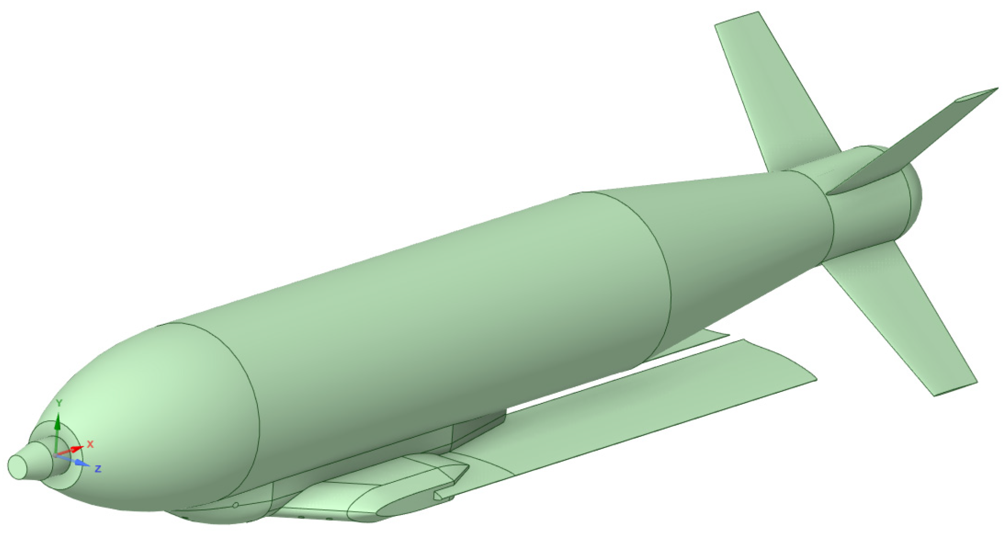
Figure 1. Geometric model of the external store.
Aerospace 13 00336 g001
Figure 2. Different possible configurations: (a) Inner; (b) Outer; (c) Centerline under the fuselage.
Aerospace 13 00336 g002
Figure 3. Computational domain and subdomain.
Aerospace 13 00336 g003
Figure 4. Surface mesh on the (a) external store; (b) whole aircraft.
Aerospace 13 00336 g004
Figure 5. Mesh under the external store.
Aerospace 13 00336 g005
Figure 6. Variation in lift, drag and pitch moment coefficient at zero angle-of-attack with mesh size.
Aerospace 13 00336 g006
Figure 7. Forward and aft ejector forces.
Aerospace 13 00336 g007
Figure 8. Flight: (a) path; (b) orientation when the store is separated from the outer station at M = 0.6.
Aerospace 13 00336 g008
Figure 9. Flight: (a) path; (b) orientation when the store is separated from the inner station at M = 0.6.
Aerospace 13 00336 g009
Figure 10. Pitch motion of the store tail released from the outer pylon at M = 0.6 after: (a) t = 0 s; (b) t = 0.14 s.
Aerospace 13 00336 g010
Figure 11. Diagram of the store’s trajectory from the inner pylon at M = 0.6 in: (a) xz-plane; (b) yz-plane.
Aerospace 13 00336 g011
Figure 12. Flight path from the inner pylon at M = 0.6 at: (a) t = 0 s; (b) t = 0.2 s; (c) t = 0.4 s; (d) t = 0.6 s.
Aerospace 13 00336 g012
Figure 13. Flight path from the fuselage centerline at M = 0.6 at: (a) t = 0 s; (b) t = 0.15 s; (c) t = 0.25 s; (d) t = 0.45 s.
Aerospace 13 00336 g013
Figure 14. Collision between the store and aircraft at M = 0.7 at t = 0.126 s.
Aerospace 13 00336 g014
Figure 15. Flight path from the outer pylon with ejection forces at M = 0.6 at: (a) t = 0 s; (b) t = 0.1 s; (c) t = 0.15 s; (d) t = 0.2 s.
Aerospace 13 00336 g015
Figure 16. Difference between the impulse and gravitational separation at t = 0.15 s.
Aerospace 13 00336 g016
Figure 17. Flight path from the inner pylon with ejection forces at M = 0.8 at: (a) t = 0 s; (b) t = 0.05 s; (c) t = 0.10 s; (d) t = 0.20 s; (e) t = 0.30 s; (f) t = 0.40 s.
Aerospace 13 00336 g017
Figure 18. Flight path from the outer pylon with ejection forces at M = 0.9 at: (a) t = 0 s; (b) t = 0.05 s; (c) t = 0.10 s; (d) t = 0.20 s; (e) t = 0.30 s; (f) t = 0.40 s.
Aerospace 13 00336 g018
Figure 19. Comparison of turbulent flow structures around the store at t = 0.4 s for: (a) M = 0.6; (b) M = 0.8.
Aerospace 13 00336 g019
Figure 20. The effect of speed and angle-of-attack on the flight path of a store after ejecting from the inner pylon.
Aerospace 13 00336 g020
Figure 21. Flight path of the store from different positions at M = 0.9.
Aerospace 13 00336 g021
Figure 22. Flight path of the store from the fuselage centerline pylon.
Aerospace 13 00336 g022
Figure 23. Store velocity components at different initial conditions: (a) gravitational separation at M = 0.6 and angle-of-attack 0°; (b) impulse separation at M = 0.6 and angle-of-attack −2°.
Aerospace 13 00336 g023
Figure 24. Store velocity components for the impulse separation at M = 0.9 and angle-of-attack −2°.
Aerospace 13 00336 g024
Table 1. Record of simulations from the inner pylon for gravitational separation.
α\M0.60.70.80.9
−2°CompletedCollision at
t = 0.137 s
Collision at
t = 0.069 s
Collision at
t = 0.049 s
CompletedCollision at
t = 0.153 s
Collision at
t = 0.073 s
Omitted
CompletedCollision at
t = 0.170 s
OmittedOmitted
CompletedCollision at
t = 0.185
Collision at
t = 0.092 s
Omitted
Table 2. Record of simulations from the outer pylon for gravitational separation.
α\M0.60.70.80.9
−2°CompletedCollision at
t = 0.126 s
Omitted Omitted 
CompletedCollision at
t = 0.131 s
OmittedOmitted
CompletedCollision at
t = 0.155 s
OmittedOmitted
CompletedCollision at
t = 0.167 s
OmittedOmitted
Disclaimer/Publisher’s Note: The statements, opinions and data contained in all publications are solely those of the individual author(s) and contributor(s) and not of MDPI and/or the editor(s). MDPI and/or the editor(s) disclaim responsibility for any injury to people or property resulting from any ideas, methods, instructions or products referred to in the content.