Article

An Ultra-High-Aspect-Ratio Telescopic Continuum Robot Design for Aero-Engine Borescope Inspection

School of Mechatronical Engineering, Beijing Institute of Technology, No. 5 Zhongguancun South Street, Haidian District, Beijing 100081, China
*
Author to whom correspondence should be addressed.
Aerospace 2026, 13(3), 291; https://doi.org/10.3390/aerospace13030291
Submission received: 23 January 2026 / Revised: 11 March 2026 / Accepted: 16 March 2026 / Published: 19 March 2026
(This article belongs to the Section Aeronautics)

Abstract

Conventional borescopes are limited by inadequate mechanical flexibility, poor environmental adaptability and reachability, and heavy reliance on operator expertise during aero-engine inspections, making it difficult to meet the demands for efficient and dependable in situ nondestructive evaluation (NDE). This paper presents a novel telescopic continuum robot mechanism with an ultra-high aspect ratio (63.75:1) and three constant-curvature segments, achieving a synergistic design between the robot’s body structure and the long-stroke linear actuator of its central backbone to realize ultra-high-aspect-ratio configurations. This design improves the robot’s ability to access complex and confined internal spaces within aero-engines, thereby reducing inspection blind spots. Furthermore, a configuration-space control strategy integrating kinematic decoupling and driving tendon tension compensation is proposed. This strategy addresses the issues of multi-segment actuation coupling and tendon slack, ensuring the motion control performance for in situ aero-engine blade inspection. The feasibility of the mechanism design was validated through an experimental simulation platform incorporating both turbine blade and compressor blade scenarios. This work offers a new solution for in situ NDE in aero-engines by synergistically integrating an innovative ultra-high-aspect-ratio telescopic mechanism with a dedicated configuration-space controller that addresses multi-segment coupling and tendon slack.

1. Introduction

As the core component of aircraft, the superior working performance of an aero-engine is the decisive factor for the successful execution of flight missions. However, due to prolonged exposure to extremely harsh environments, such as high temperature, high pressure, and high-frequency vibrations [1], regular monitoring of its health status is crucial, especially for compressor and turbine blades, which require more frequent inspection in situ for their prediagnosis. The internal structure of an aero-engine is highly complex, particularly in the compressor and turbine sections, where the compact arrangement of multi-stage blades and the narrow inspection ports pose significant challenges for in situ inspection. At present, the mainstream inspection approach is still conventional manual inspection, which heavily depends on the experience of professional maintenance technicians to acquire high-quality images of the region under inspection. For the blades close to the inspection ports, maintenance personnel can diagnose them by resorting to industrial borescopes. However, for the inside blades, the strictly limited space hinders them from being fully inspected. This often results in borescope technology providing an innovative solution for blade disassembly, a process that consumes significant manpower and time, which reduces inspection efficiency and prolongs the aircraft turnaround time.
Borescope technology offers an innovative approach to the in situ inspection of aero-engines, enabling maintenance personnel to insert the device into narrow gaps or inspection ports to access deep blades and achieve indirect visualization through display screens [2]. However, traditional industrial borescopes are flexible and rely on their passive deformation against the environment for passability and posture adjustment in the narrow, curved space. Realizing the inspection of multi-stage blades through a single inspection port is tremendously difficult since inspection personnel find it hard to control the position and orientation of the probe head and find it difficult to traverse gaps in-between blades or enter the occluded areas. A complete inspection of a single-stage blade often requires multi-person coordination, which increases the damage risk of the borescope because of impacting the blades invoked by improper operation [3].
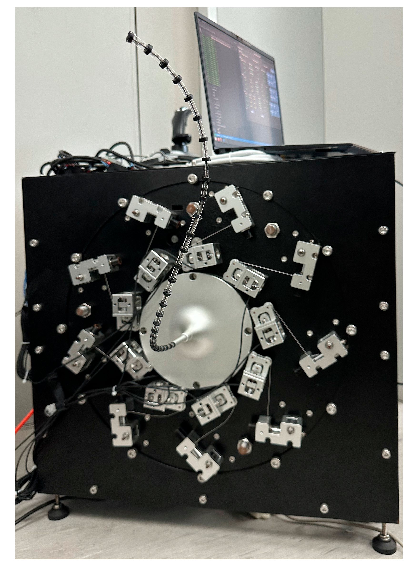
In this context, continuum robots demonstrate significant potential for complex operations within confined spaces. Their bionic spine-inspired structure possesses full-range continuous deformation capabilities, enabling navigation through curved paths. Equipped with deployable inspection sensors or tools at their distal end, they can accurately achieve both body shape and end-effector pose control, meeting the adaptability requirements of aero-engine inspection environments [4], which is impossible for industrial borescopes. Recent successful applications of continuum robots in the medical field have further highlighted their potential for industrial inspection. However, existing designs of self-supporting, long, slim continuum robots (operating without relying on external environmental support) still face challenges: achieving a high-aspect-ratio structure (length-to-diameter ratio typically below 50), lacking continuous body telescoping functionality, and difficulties in realizing long-stroke actuation for telescoping mechanisms. These limitations hinder their application in aero-engine inspection [5,6,7]. To address these limitations inherent in both existing continuum robots and industrial borescopes, thereby enhancing inspection efficiency and effectiveness, this paper proposes an Ultra-High-Aspect-Ratio Telescopic Continuum robot (UHAR-TC robot, Figure 1). The primary innovations of this design are manifested in the following four aspects:
•
Ultra-High-Aspect-Ratio Robot Body Design
The robot body consists of three nested Ni-Ti alloy tubes, tendon-guiding disks, and springs to enable telescopic motion. It extends to 510 mm (retracts to 160 mm) with an 8 mm diameter, achieving an aspect ratio of 63.75. This allows entry through 9 mm inspection ports and navigation through multi-stage blade passages for in situ inspection.
•
Unlimited Axial Telescoping Drive Mechanism
A hand-over-hand coordination scheme using one floating and three fixed pneumatic grippers enables slip-free, infinite axial telescoping of a single central backbone, overcoming the limitations of actuator stroke and material bending strength.
•
Configuration space control based on kinematic decoupling and tendon tension compensation
A configuration-space controller integrating kinematic decoupling and tension compensation is proposed to effectively address multi-segment coupling and tendon slack. This approach enables decoupled control via inverse Jacobian mapping and suppresses motion hysteresis through PID-based tension regulation.
•
Duo-Scenario Integrated Experimental Validation
A dual-scenario simulated test platform (turbine and compressor blades) was constructed to validate the agile mobility of the UHAR-TC robot in confined spaces and its capability to acquire high-quality blade images via an on-board pinhole camera.
In summary, this paper systematically addresses the key challenges of continuum robots in the in situ inspection of aero-engines, from mechanism design and control methods to experimental validation, thereby laying a theoretical and technical foundation for their engineering applications.
The remainder of this paper is organized as follows: Section 2 reviews the state-of-the-art in robots for aero-engine inspection and continuum robot research. Section 3 details the mechanical design principle of the UHAR-TC robot, including its body and actuation system. Section 4 presents the kinematic modeling and the proposed configuration-space control strategy with kinematic decoupling and tension compensation. Section 5 experimentally validates the proposed robotic system, confirming the feasibility of the overall design. Section 6 systematically discusses the core innovations, technical comparisons, effectiveness, and limitations of the control strategy and engineering application prospects of the robot. Finally, Section 7 concludes the paper.

2. The Literature Review

2.1. The State-of-the-Art of Robots for Aircraft Engine Applications

Traditional rigid-link industrial robots are widely used in aero-engine applications. For instance, a team from Hebei University of Technology in China has achieved the polishing of aircraft engine blades with a robotic arm [8], and French research teams have employed mobile autonomous navigation robots for the real-time assembly inspection of external mechanical components of aero-engines. However, traditional robotic arms are constrained by their workspace limitations, restricting their operation to engine surface tasks only within accessible free space near ground level [9].
Novel climbing robots, leveraging biomimetic locomotion mechanisms, achieve stable adhesion and movement on structural surfaces at arbitrary inclination angles. This motion capability overcomes the workspace limitations inherent in traditional robotic arms, thereby offering a new paradigm for aircraft engine inspection [10]. For example, various robots utilizing legged locomotion with negative pressure adhesion or vortex-based adhesion have been applied to aircraft skin inspection [11,12,13]; UK-developed climbing robots are capable of carrying heavy-duty inspection payloads [14]; climbing robots developed by the Civil Aviation University of China (CAUC) demonstrate effective steering and obstacle-surmounting capabilities [15]. However, when applied to internal inspection of the engine, climbing robots face constraints due to their structural dimensions and poor cavity adaptability. This leads to insufficient spatial reachability within confined and narrow internal spaces.
Micro-scale biomimetic robots, leveraging their compact size advantage, offer innovative solutions for aero-engine inspection. Several proof-of-concept prototypes have been developed. For instance, a team from Harvard University deployed micro-robot swarms into hard-to-reach engine regions for visual inspection [16]; researchers at the Harbin Institute of Technology (HIT) developed a miniature crawling robot based on a flexible composite material structure and piezoelectric actuation mechanism for in situ inspection tasks within aero-engines [17]. However, both approaches face risks in practical applications, such as disconnection or loss of the robot due to unreliable control systems. This may necessitate engine disassembly for retrieval.
In contrast, continuum robots demonstrate higher efficiency, precision, and safety than these micro-scale robots for aero-engine inspection. This is attributed to their biomimetic flexible structure, high environmental adaptability, and multi-task integration capability. These characteristics make them particularly suitable for inspecting the complex internal structures of modern high-bypass-ratio engines. For example, research teams in the UK have conducted in-depth studies on the application of continuum robots for aero-engine maintenance and inspection [18]. They proposed a collaborative working scheme employing two continuum robots. This scheme enables coating repair without requiring engine disassembly, demonstrating significant advantages.

2.2. Research Status of Continuum Robots

Advances in computing technologies, materials science, and manufacturing processes have driven the development of continuum robots. Inspired by biological organisms such as snakes and plant tendrils, these robots feature a continuous, bendable, spine-like structure composed of flexible materials. Their shape configuration is achieved by controlling this structure through internal or external actuation [19]. Research on continuum robots traces its origins back to the 1960s, with significant acceleration occurring in the late 1990s [20]. Initially termed elephant trunks, tentacles, or flexible manipulators, these robots were developed for applications across multiple sectors, including manufacturing and aerospace. Their operational value lies particularly in accessing regions inaccessible to traditional rigid robots.
In terms of design, the core element of a continuum robot is its backbone. This backbone can be constructed from rigid segments, flexible segments, or a combination of both. Based on the actuation method applied to the backbone, continuum robots are categorized into two primary types: externally actuated and internally actuated. External actuation encompasses methods such as tendon-driven, concentric tube, and rod-driven mechanisms. Examples include tendon-driven continuum robots developed by US research teams [21,22], concentric tube continuum robots [23], and rod-driven continuum robots developed by Shanghai Jiao Tong University (SJTU) [24]. While each type offers distinct advantages, they also share limitations such as constrained stiffness, increased control complexity, and larger overall dimensions. Internal actuation controls the shape of the backbone via driving mechanisms embedded within it. Common approaches include pressurized gas or liquid (fluidic) actuation and smart material-based actuation [25]. For instance, gas-actuated continuum robots have been developed by German teams [26], and vine-inspired continuum robots by UK teams [27]. These robots offer advantages in areas like lightweight design and inherent flexibility. However, they face challenges, including limited payload capacity and reliability concerns.
Regarding modeling methodologies, the modeling of continuum robots necessitates incorporating theories such as material mechanics. It also requires combining analytical approaches from kinematics and system mechanics, resulting in significant differences from traditional robotic arm modeling. The modeling approaches for these robots are broadly categorized into three major types: reduced-dimension models, variable-curvature models, and piecewise models. Reduced-dimension models represent the robot as a finite state-space system. Among these, the constant curvature assumption is the most widely applied method; however, it suffers from deviations caused by its idealized assumptions [28]. Variable-curvature models utilize continuum mechanics theory, enabling a precise description of complex deformations. However, they are computationally intensive [29]. Piecewise models simplify the backbone into a system of discrete elements, thereby reducing modeling complexity. Yet this approach achieves relatively lower accuracy [30].
Regarding control strategies, continuum robot control approaches are structured across three levels: low-level, mid-level, and high-level. At the low level, static controllers based on pre-existing models are widely applied. The constant curvature approximation has proven effective in this context [31]; at the mid-level, closed-loop control strategies operating in both task space and joint space offer distinct advantages [32]. High-level control necessitates integrating planning strategies to accomplish tasks such as generating collision-free paths. For instance, continuum robots emulating biomimetic locomotion modes like circumnutation (vine–tendril circling) and coiling demonstrate significant potential for industrial inspection applications [33,34].

2.3. Application of Continuum Robots in Aero-Engine Inspection

Although fundamental research on continuum robots has grown rapidly, the number of teams achieving successful technology deployment for in situ aero-engine inspection remains limited. Consequently, engineering implementation has emerged as a prominent new research focus. Institutions such as the University of Nottingham (UK), Nanjing University of Aeronautics and Astronautics (NUAA, China), and Xi’an Jiaotong University (XJTU, China) have made significant breakthroughs. In collaboration with industrial partners, the University of Nottingham designed dual-structure continuum robots [35] and tendon-driven continuum robots [36]. While these designs achieved breakthroughs in workspace and obstacle avoidance capabilities, they suffer from limited applicability. NUAA developed continuum robots capable of contact-based blade inspection [37]. However, these robots exhibit insufficient consideration of miniaturization requirements and shape constraints. XJTU created a multi-segment continuum robot that demonstrated practical utility in simulated testbed evaluations [38]. Nevertheless, the testbed failed to replicate the characteristics of real engine blades. This limitation prevents the robot from effectively addressing the inspection demands of small-scale engines.
The recent literature has emphasized that advanced mechanical design must be holistically integrated with considerations of dynamics, reliability, and adaptability. For instance, the analysis of rigid–flexible coupling systems, as discussed by Zhou et al. [39], highlights the importance of addressing underactuated vibration characteristics at the structural level to facilitate subsequent control. Furthermore, ensuring the dependability of such mechanisms in uncertain environments calls for rigorous reliability-based design optimization frameworks, such as the adaptive Kriging-assisted method developed by Ye et al. [40]. Looking beyond fixed-topology designs, the concept of a configuration-independent capability space proposed by Liu et al. [41] for reconfigurable robots offers a visionary direction for future mechanical design, suggesting ways to achieve greater task generalization through modular and adaptive structures. The design of our UHAR-TC robot, with its ultra-high-aspect-ratio and telescopic segments, contributes to this body of knowledge by providing a practical solution for accessing confined spaces, while drawing inspiration from these broader trends in structural analysis and design methodology.

3. Mechanical Design Principle

3.1. Mechanical Design of the UHAR-TC Robot Body

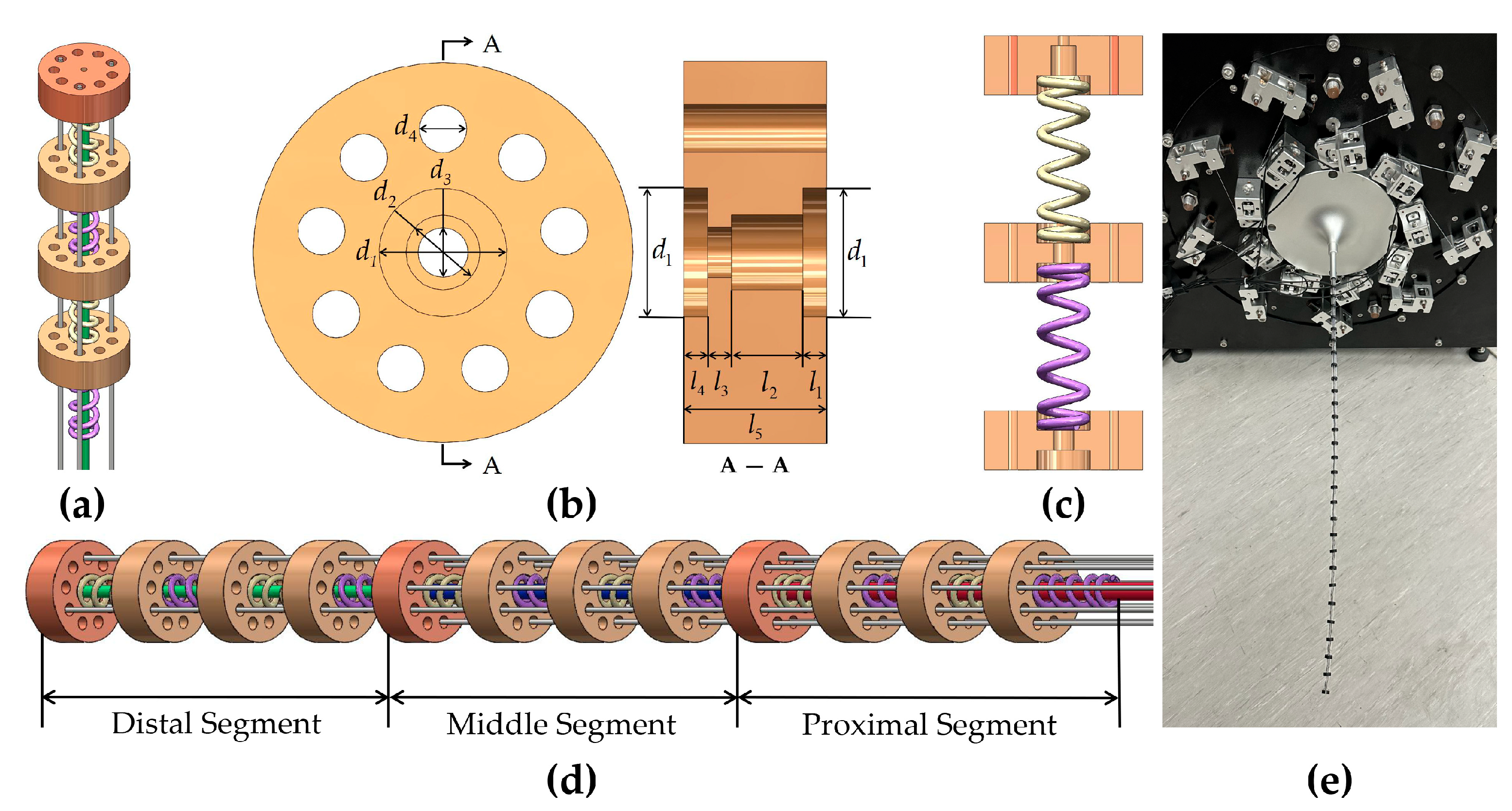
As shown in Figure 2a, each active bending segment of the UHAR-TC robot consists of 1 Ni-Ti alloy tube (in the austenitic phase at room temperature), 3 driving tendons, multiple tendon-guiding disks, and multiple springs (the actual number depends on the length requirement of the robot’s body). To clearly illustrate the three-segment structure, each segment in Figure 2d is depicted with a schematic configuration containing only 4 tendon-guiding disks and 4 springs. Three Ni-Ti alloy tubes are concentrically nested to form the central backbone. As shown in Figure 2e, the prototype incorporates 3 active bending segments, each equipped with 10 tendon-guiding disks; among these, 1 end disk is adhesively bonded to the tip of the Ni-Ti alloy tube, while the remaining 9 disks move freely axially. The parameters of the Ni-Ti alloy tubes are listed in Table 1. As depicted in Figure 2b, each guiding disk features 1 central hole (for Ni-Ti alloy tube insertion) and 9 evenly distributed tendon-guiding holes; counterbores are machined at both ends of the central hole to secure the springs, and the disk parameters are detailed in Table 2. The tendons are fastened to the end disk via knotting; each tendon then passes sequentially through all subsequent guiding disks along its segment before reaching the actuation unit. As illustrated in Figure 2c, all guiding disks within a segment are adhesively bonded and connected by alternately arranged left-handed and right-handed coil springs. The springs, made of 65 Mn steel, have an outer diameter of 2.65 mm, a wire diameter of 0.3 mm, a free length of 25 mm, 20 active coils, and feature flat-ground ends.

3.2. Actuation System Design

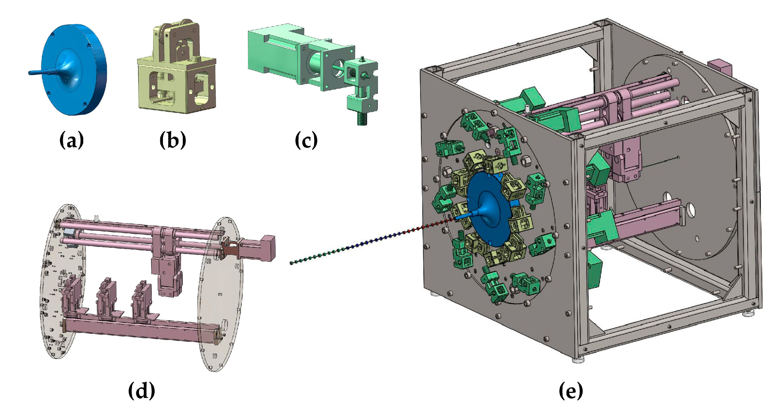
As shown in Figure 3, the actuation system of the UHAR-TC robot comprises 1 guide base, 9 tension sensing units, 9 tendon actuation units, and 1 telescopic actuation unit. The central backbone passes through the center hole of the guide base and extends to the telescopic actuation unit; the 9 driving tendons exit the robot body, sequentially enter the guide base, pass through tendon-guiding holes into the tension sensing units, proceed to the tendon actuation units, and finally anchor their ends onto threaded spools.
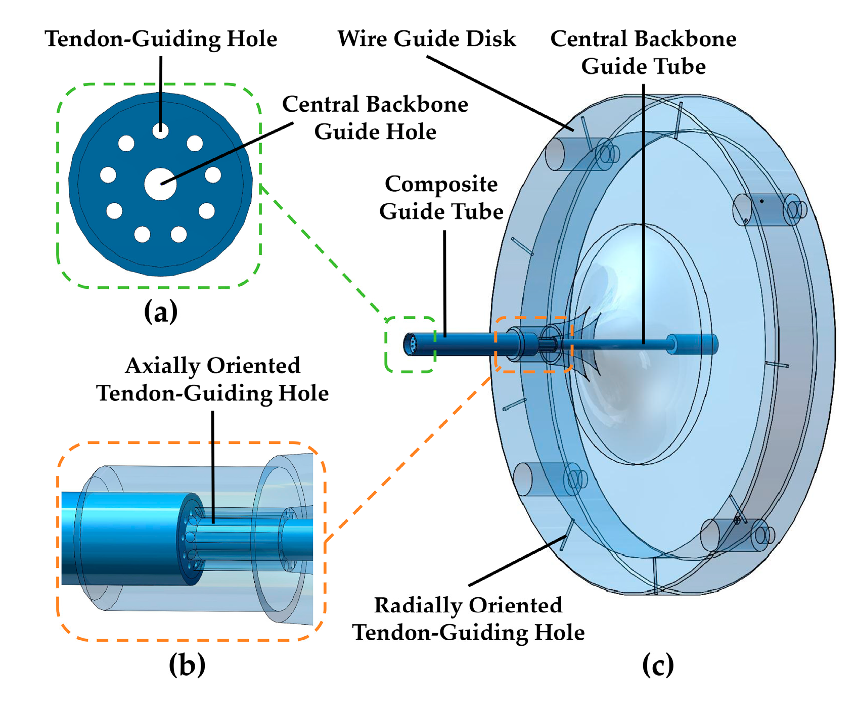
As shown in Figure 4, the guide base consists of a wire guide disk, a composite guide tube, and a central backbone guide tube. The composite guide tube contains 1 central backbone guide hole and 9 circumferentially evenly distributed tendon-guiding holes; the wire guide disk incorporates 9 axially oriented tendon-guiding holes and 9 radially oriented tendon-guiding holes, both maintaining identical circumferential distribution angles. The central backbone guide tube features only 1 central backbone guide hole at its core. The composite guide tube is adhesively bonded to the wire guide disk, with strict angular alignment ensured between their tendon-guiding holes. The central backbone guide tube inserts into the central hole of the wire guide disk and connects via a transition fit. Each driving tendon sequentially passes through the tendon-guiding holes of the composite guide tube, advances through the circumferential and radial holes of the wire guide disk, and finally exits from the guide base.
As shown in Figure 5, the tension sensing unit comprises a load cell, 2 linear bearings, a movable pulley base, a movable pulley, a fixed pulley bracket, and 2 fixed pulleys. The driving tendon enters the unit via fixed pulley 1, winds around the movable pulley, and exits from fixed pulley 2. The two fixed pulleys collectively support the driving tendon and apply an upward force to the movable pulley; the load cell obtains the tendon tension value by measuring the force exerted on the movable pulley.
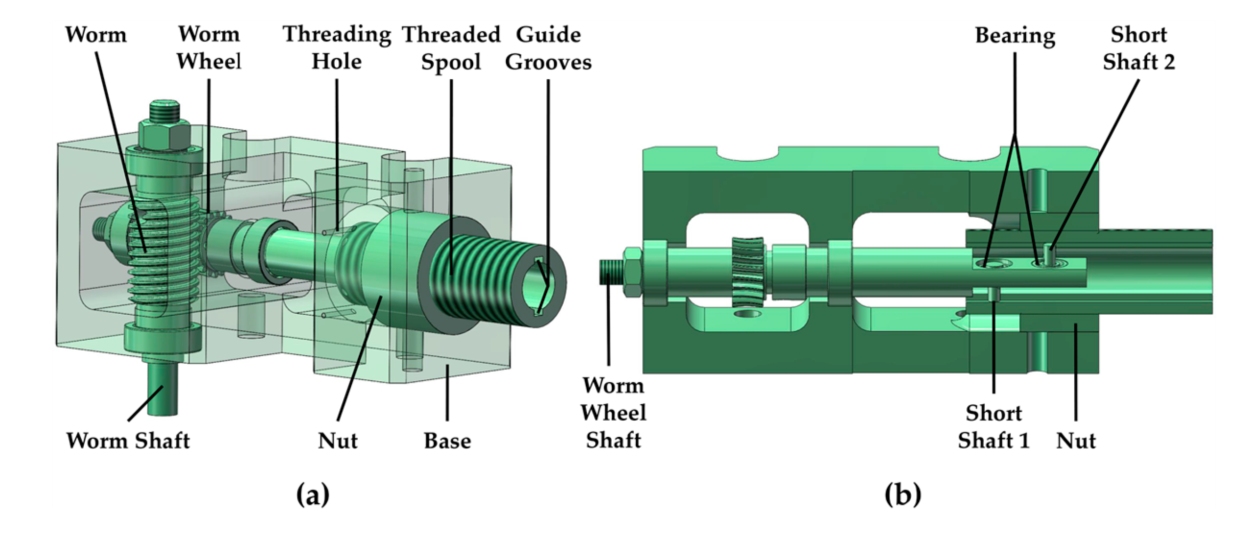
As shown in Figure 6, the tendon actuation unit consists of a base, a worm gear reducer (including a worm wheel, a worm, a worm wheel shaft, and a worm shaft), and a thread-based spooling module (comprising a nut, a threaded spool, short shaft 1, short shaft 2, and bearings). Along the power transmission path, a stepper motor is rigidly coupled to the worm shaft via a coupling, serving as the system’s power source. The motor output torque is transmitted to the worm through worm-gear meshing, and a primary speed reduction is achieved, thereby driving the worm wheel shaft to rotate. The worm wheel shaft features dual through-holes at its end, each housing short shaft 1 and short shaft 2 via bearings, forming a dual-support structure. The short shaft assembly engages with guide grooves on the threaded spool’s inner wall to form a sliding pair; while transmitting torque circumferentially, it achieves axial displacement compensation constrained by the nut. This unit provides two core functions: (1) precise tendon winding/unwinding by driving the threaded spool’s rotation via the worm wheel shaft; and (2) dynamic self-locking through coordinated circumferential rotation and axial movement of the spooling module, ensuring the tendon exit direction remains dynamically aligned with the threading hole axis.
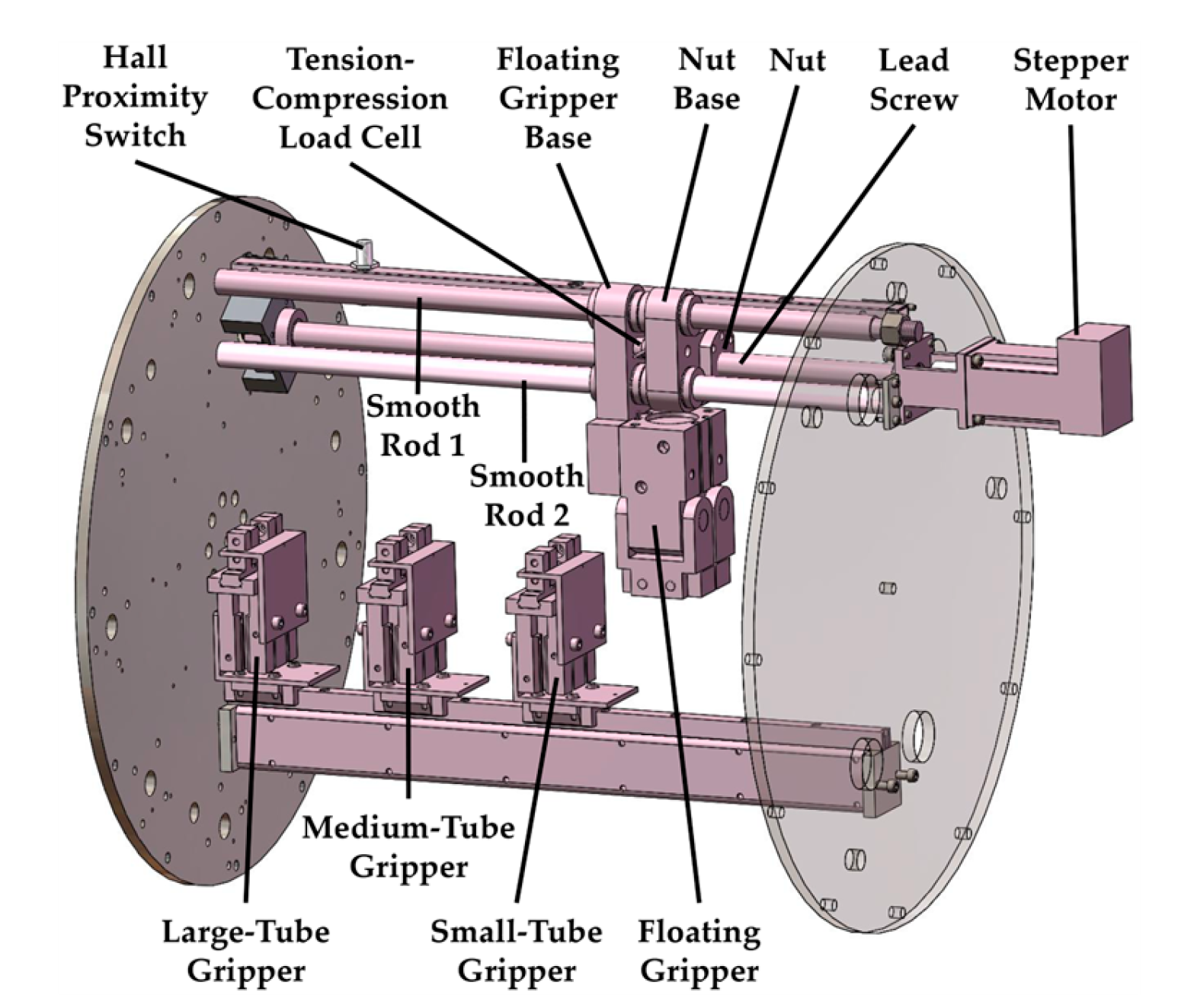
As shown in Figure 7, the core function of the telescopic actuation unit achieves precise extension/retraction of the UHAR-TC robot’s central backbone. This unit employs an alternating gripping strategy using pneumatic grippers, enabling stable push-pull actuation even for low-stiffness Ni-Ti alloy tubes while preventing buckling instability during advancement. It comprises four subsystems: (1) a backbone gripping mechanism with floating, fine-tube, medium-tube, and coarse-tube grippers (all pneumatically actuated); (2) a driving assembly consisting of a stepper motor, lead screw, nut, and smooth rods 1 and 2; (3) a force measurement module with a tension-compression load cell, nut base, and floating gripper base; and (4) a stroke limit device using a Hall proximity switch. The operational principle involves the stepper motor driving the lead screw’s rotation via a coupling, which translates the nut axially. The nut is fixed to the nut base; one end of the load cell mounts to this nut base, while the other connects to the floating gripper base. This configuration allows real-time push-pull force measurement during floating gripper movement, indirectly monitoring the central backbone’s load state to prevent damage from excessive thrust.
The three nested Ni-Ti alloy tubes forming the central backbone are gripped by dedicated fixed grippers: fine-tube, medium-tube, and coarse-tube grippers, respectively. The floating gripper moves into the position between coarse- and medium-tube grippers; a single actuation cycle achieves up to 10 mm extension/retraction of the coarse tube. The number of floating gripper cycles is determined by the coarse tube’s total required stroke. During coarse tube actuation by the floating gripper, the coarse-tube gripper releases its grip; when the floating gripper reaches the stroke limit, the coarse-tube gripper regrips the tube. The floating gripper then releases and returns to its initial position, preparing for the next push-pull cycle. For medium and fine tube actuation, the coordinated control logic between their floating grippers and corresponding fixed grippers (medium-tube and fine-tube grippers) follows the same release-move-clamp sequence as described for the coarse tube. The control logic for all pneumatic grippers and motion states of the three Ni-Ti alloy tubes is detailed in Table 3.

4. Kinematic Modeling and Control Strategy Design

To analyze the motion performance of the designed UHAR-TC robot, this section conducts kinematic modeling and numerical simulation studies. Under the master–slave mapping framework, a configuration space controller is designed based on kinematic decoupling and tendon tension compensation.

4.1. Kinematics Modeling and Simulation of Single-Segment Continuum Robot

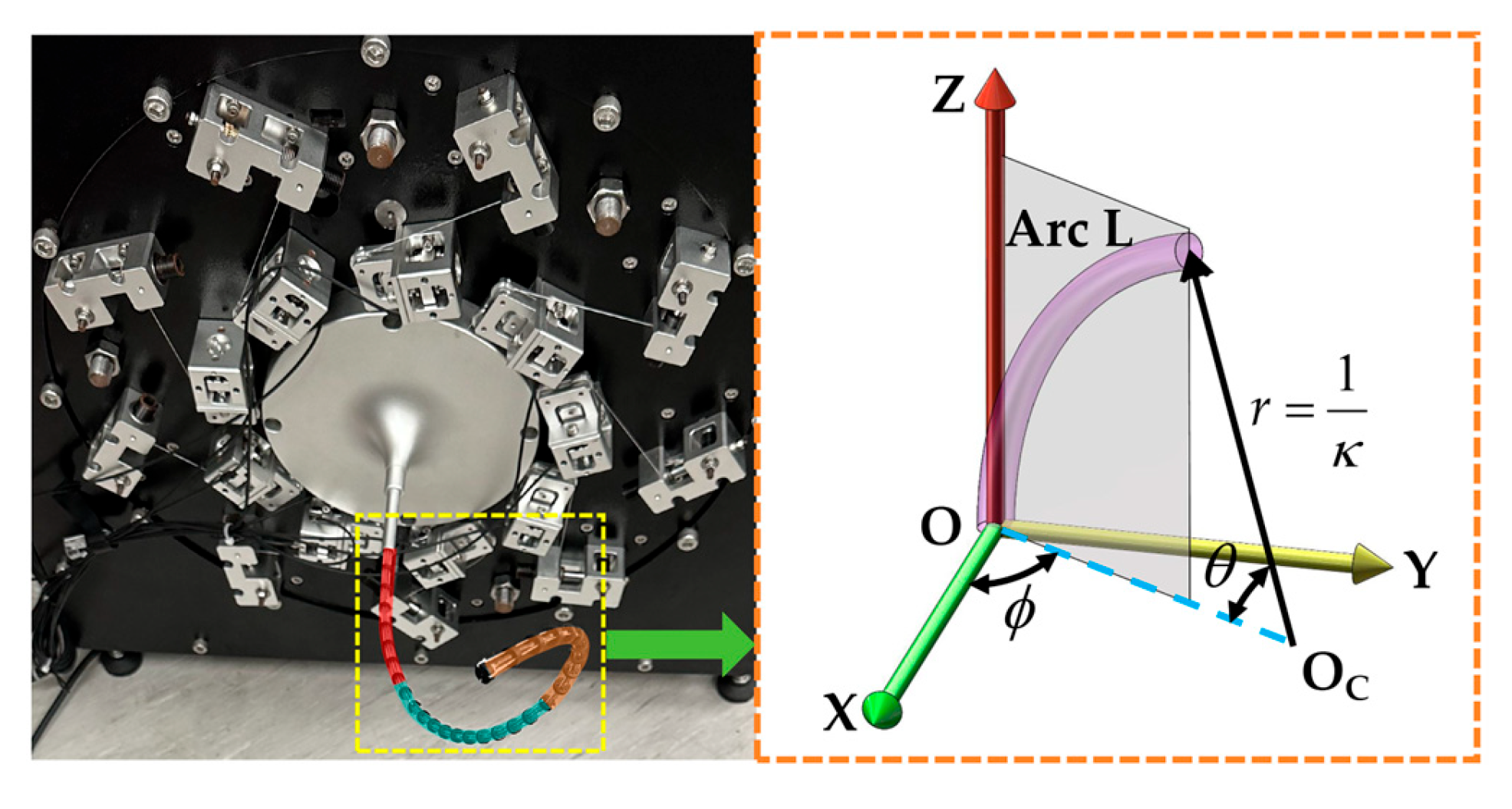
To address the infinite degrees of freedom characteristic of the UHAR-TC robot, the constant curvature assumption is adopted for model dimensionality reduction. As shown in Figure 2, the robot possesses an ultra-high aspect ratio and three telescopic active bending segments. Each active bending segment consists of 1 Ni-Ti alloy tube, 3 driving tendons, multiple tendon-guiding disks, and springs. As shown in Figure 8, the robot’s central backbone is simplified as a planar circular arc curve with uniform curvature. In the base coordinate frame Σ o o − X Y Z , r = O O c is the radius corresponding to the variable arc length L , and θ is the central angle.
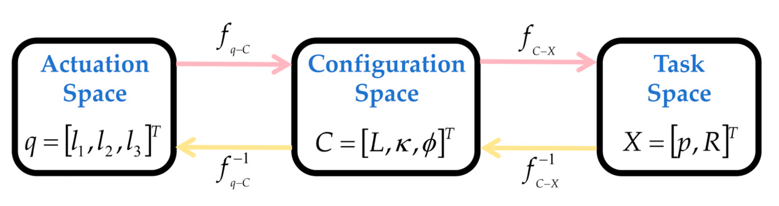
As shown in Figure 9, the mapping relationships between the actuation space q (i.e., the lengths l 1 , l 2 , and l 3 of the three driving tendons), the configuration space C (its configuration is described by three parameters: arc length ( L ) , curvature ( κ ) , and twist angle ( ϕ ) ), and the task space X (where p and R are the end-effector position vector and rotation matrix of the continuum manipulator, respectively) are established, and the analytical solutions for both forward and inverse kinematics are derived, along with numerical simulations. Where f q − C is the mapping function from the actuation space to the configuration space, f q − C − 1 is its inverse mapping; f C − X is the mapping function from the configuration space to the task space, f C − X − 1 is its inverse mapping [42].

4.1.1. Forward Kinematics

Considering the thickness of the tendon-guiding disks and the torsional stiffness of the central backbone, given three tendons with lengths l 1 , l 2 , and l 3 , and the distance from the center of the tendon-guiding disk to each tendon d , n is the number of tendon-guiding disks. Each segment has n + 1 tendon-guiding disks. Assuming the section between two adjacent tendon-guiding disks is a straight line, the segment is divided into n units. Therefore, the relationship between the tendon lengths and the arc parameters of the continuum robot can be obtained as follows [28]:
ϕ ( q ) = tan − 1 ( 3 ( l 2 + l 3 − 2 l 1 ) 3 ( l 2 − l 3 ) )
κ ( q ) = 2 l 1 2 + l 2 2 + l 3 2 − l 1 l 2 − l 2 l 3 − l 3 l 1 d ( l 1 + l 2 + l 3 )
L ( q ) = n d ( l 1 + l 2 + l 3 ) l 1 2 + l 2 2 + l 3 2 − l 1 l 2 − l 2 l 3 − l 3 l 1 sin − 1 ( l 1 2 + l 2 2 + l 3 2 − l 1 l 2 − l 2 l 3 − l 3 l 1 3 n d )
In the formula, q = [ l 1   l 2   l 3 ] T is the driving tendon length in the actuation space, and curvature κ ( q ) , twist angle ϕ ( q ) , and arc length L ( q ) are parameters in the configuration space.
In Figure 8, when ϕ = 0 , the coordinates of a point on the circular arc in the x–z plane, with center [ r   0   0 ] T and radius r , are
p = [ r ( 1 − cos θ )   0   r sin θ ] T
After obtaining the configuration parameters via the aforementioned actuation-to-configuration space mapping relationship, the homogeneous transformation matrix between the frames of two adjacent tendon-guiding disks in the task space is then derived based on the configuration space parameters. Here, R y ( θ ) represents the transformation within the x–z plane, denoting the motion of the single-segment continuum robot with a bending angle of θ ; R z ( ϕ ) denotes the rotation by an angle ϕ about the z-axis after bending. To align the end coordinate frame with the base coordinate frame, it should be right-multiplied by R z ( − ϕ ) , yielding a more general pose transformation matrix. Therefore, the relationship between the arc parameters and the pose of a single-segment continuum robot can be obtained:
T = [ R z ( ϕ ) 0 1 × 3 0 3 × 1 1 ] [ R y ( θ ) 0 1 × 3 p 1 ] [ R z ( − ϕ ) 0 1 × 3 0 3 × 1 1 ] = [ cos ϕ cos κ L − sin ϕ cos ϕ sin κ L cos ϕ ( 1 − cos κ L ) κ sin ϕ cos κ L cos ϕ sin ϕ sin κ L sin ϕ ( 1 − cos κ L ) κ − sin κ L 0 cos κ L sin κ L κ 0 0 0 1 ]

4.1.2. Inverse Kinematics

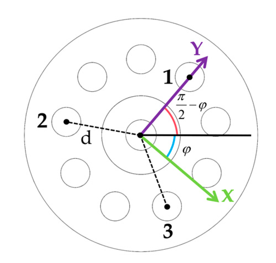
Based on the geometric constraints of the tendon-guiding disks, as shown in Figure 10, and given the end-effector position p = [ x   y   z ] T of the continuum robot, the twist angle ϕ and curvature κ can be solved in closed form. The bending direction ϕ can be determined from the x and y coordinates. Thus, the configuration space parameters for a single-segment continuum robot are derived through a geometric inverse kinematic solution based on its task space pose:
ϕ = tan − 1 y x
κ = 2 x 2 + y 2 x 2 + y 2 + z 2
θ = { cos − 1 ( 1 − κ x 2 + y 2 ) , 2 π − cos − 1 ( 1 − κ x 2 + y 2 ) , z > 0 z ≤ 0
When the endpoint p lies on the z-axis, with x = 0 and y = 0 , any value of ϕ can place the continuum robot along the z-axis. When z ≠ 0 , we choose κ = 0 and L = z ; when z is negative, it implies a negative segment length, which is physically meaningless; when z = 0, it indicates that the endpoint of the segment is at the origin. In this case, the robot can form a loop with any orientation and any radius. Hence, ϕ and κ are arbitrary, with θ = 2 π and L = 2 π / κ .
The driving tendon lengths in the actuation space are analytically solved, yielding the inverse kinematic relationship from arc parameters to tendon lengths as follows:
{ l 1 = 2 n sin ( κ L 2 n ) ( 1 κ − d sin ϕ ) l 2 = 2 n sin ( κ L 2 n ) ( 1 κ − d sin ( π 3 + ϕ ) ) l 3 = 2 n sin ( κ L 2 n ) ( 1 κ − d cos ( π 6 + ϕ ) )
where d is the distance from the center of the driving tendon to the center of the tendon-guiding disk.

4.1.3. Numerical Simulation

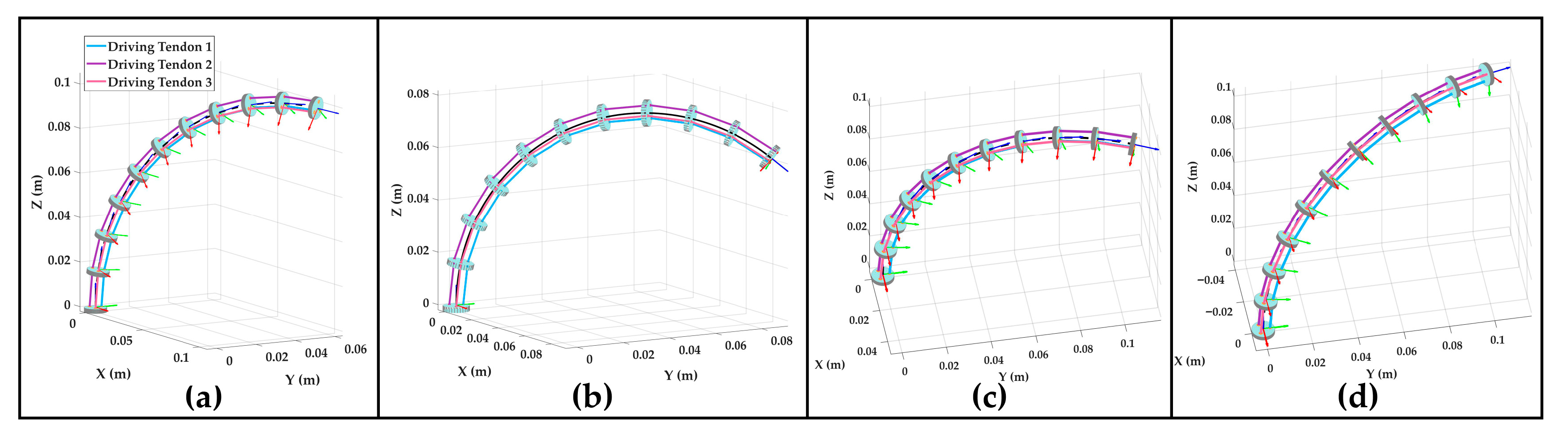
To validate the geometric relationship expression between the driving tendon lengths and the robot configuration, given the configuration parameters of a single segment, the local coordinate frame of each tendon-guiding disk is calculated via forward kinematics, and the corresponding tendon-guiding holes of all adjacent tendon-guiding disks are geometrically reconstructed with straight lines based on the distance between the tendon-guiding holes and the central backbone. Figure 11a,b demonstrates the robot undergoing a bending motion within a single plane, while Figure 11c,d demonstrates the robot performing a twisting motion under the same bending curvature.
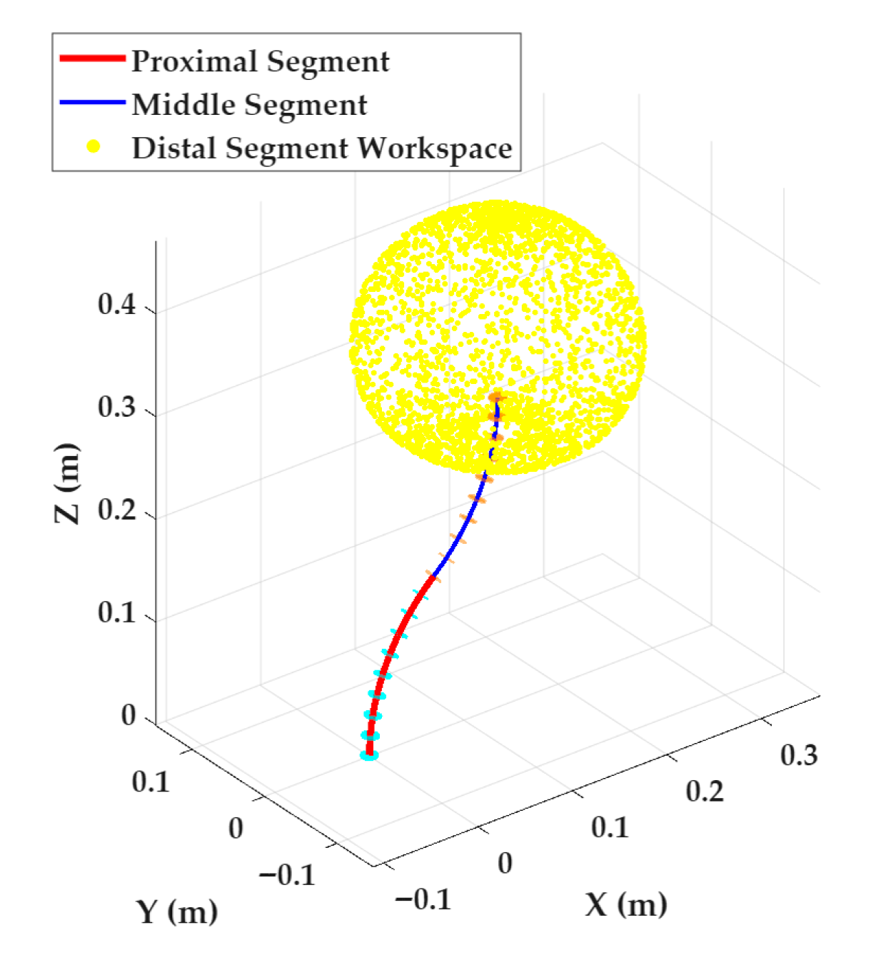
For the workspace of a single-segment continuum robot, with the shapes of the proximal and middle segments arbitrarily fixed, sampling is performed solely on the configuration space of the distal segment. In the experimental parameter settings, the length of each segment is set to its maximum extension of 0.17 m, and the complete workspace is constructed using 30,000 sampling points. As shown in Figure 12, the generated three-dimensional point cloud distribution of the distal segment workspace exhibits typical convex hull characteristics.
It should be specifically noted that although the workspace calculation is based on specific initial poses of the proximal and middle segments, adjusting the poses of these two segments only alters the orientation parameters of the entire workspace without affecting its 3D configuration. Therefore, this simulation method effectively characterizes the workspace properties of the single-segment continuum robot. Furthermore, the segment length of the robot only influences the spatial scale of the 3D configuration.

4.2. Multi-Segment Kinematics and Workspace Simulation

Although pulling the distal segment of a tendon-driven continuum robot may affect the shape of its proximal segment to some extent, the multi-disk guide design and the method of maintaining constant tendon tension via tension sensors enable the segments of this continuum robot to be considered decoupled. Consequently, the forward kinematics of serial robots can be extended to this scenario.
When two continuum segments are connected together, since the central backbone does not twist, the arc twist angle of the following segment is its actual twist angle minus the actual twist angle of the preceding segment. Therefore, the forward kinematics formula for an m-segment continuum robot is
T r o b o t = T 1 ( q 1 ) T 2 ( q 2 ) … T m ( q m )
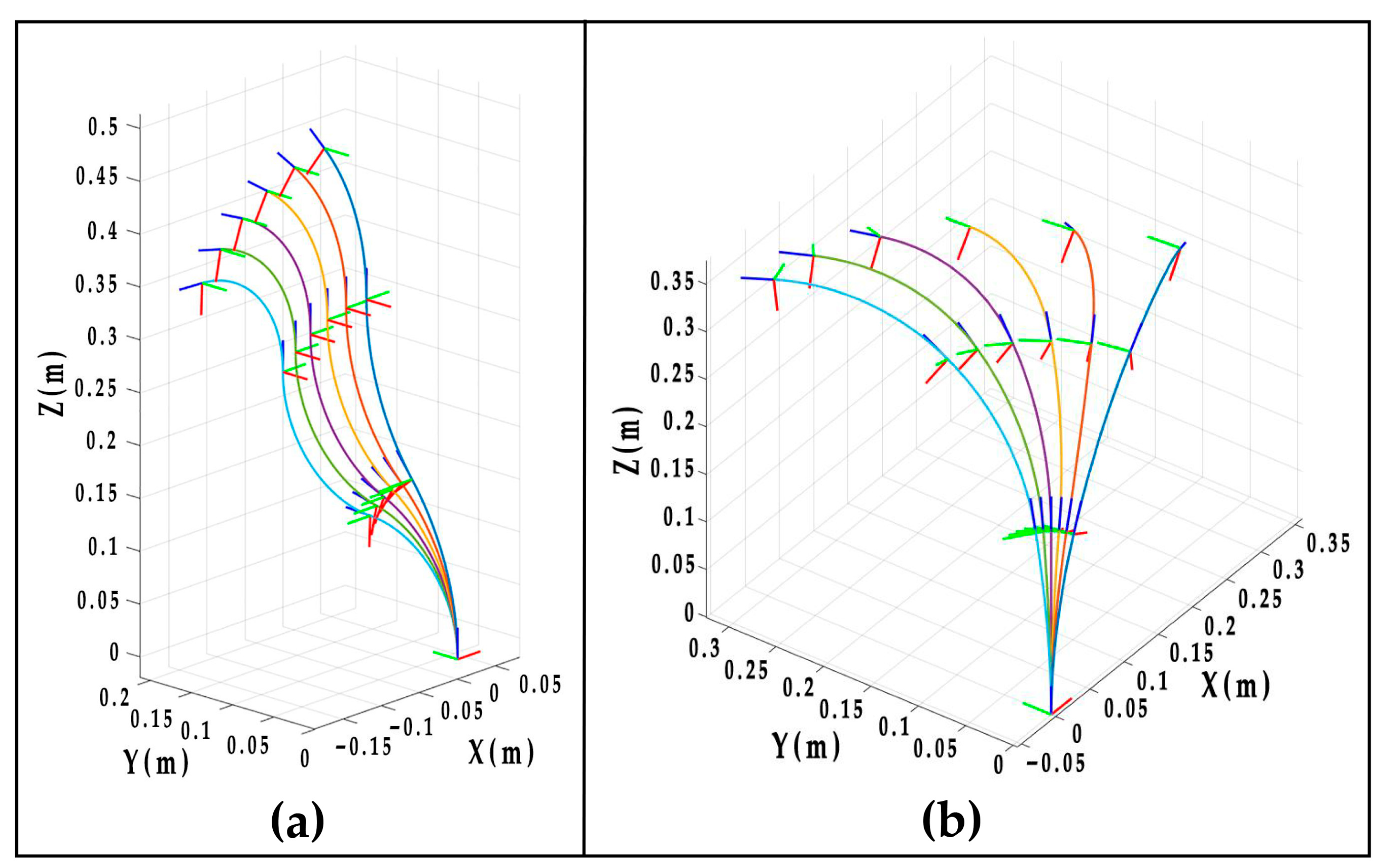
For the three-segment continuum robot (with a single-segment length of 170 mm), the experimental results demonstrate that: with the twist angle ( ϕ 1 = π / 2 , ϕ 2 = π , ϕ 3 = 3 π / 2 ) fixed and increasing the curvature (from κ = 4 m − 1 to κ = 9 m − 1 ), the coordinate frames of all segments exhibit a consistent motion pattern, rotating about the Y-axis of the base frame (Figure 13a); with the curvature ( κ 1 = 3 m − 1 , κ 2 = 4 m − 1 , κ 3 = 5 m − 1 ) fixed, and the twist angle varied continuously (from ϕ = π / 20 to 3 π / 10 ), its end effector poses is shown in Figure 13b.
Building upon the aforementioned forward kinematics verification, the numerical inverse kinematics algorithm is verified for arbitrarily given end-effector poses. Since the constrained segment length is constant, the joint variables of the three-segment continuum robot can be expressed as c = [ κ 1 , ϕ 1 , κ 2 , ϕ 2 , κ 3 , ϕ 3 ] T , the desired configuration parameters κ 1 , ϕ 1 , κ 2 , ϕ 2 , κ 3 , ϕ 3 for the three-segment continuum are set to 2 m − 1 , 0 , 5 m − 1 , π / 2 , 8 m − 1 , and π , respectively. The error between the configuration parameter values computed by the numerical solution and the ideal values is compared, with detailed computational results provided in Table 4. The accuracy of the inverse kinematics solution is within the preset tolerance error, and the iteration terminates when this tolerance error is reached.
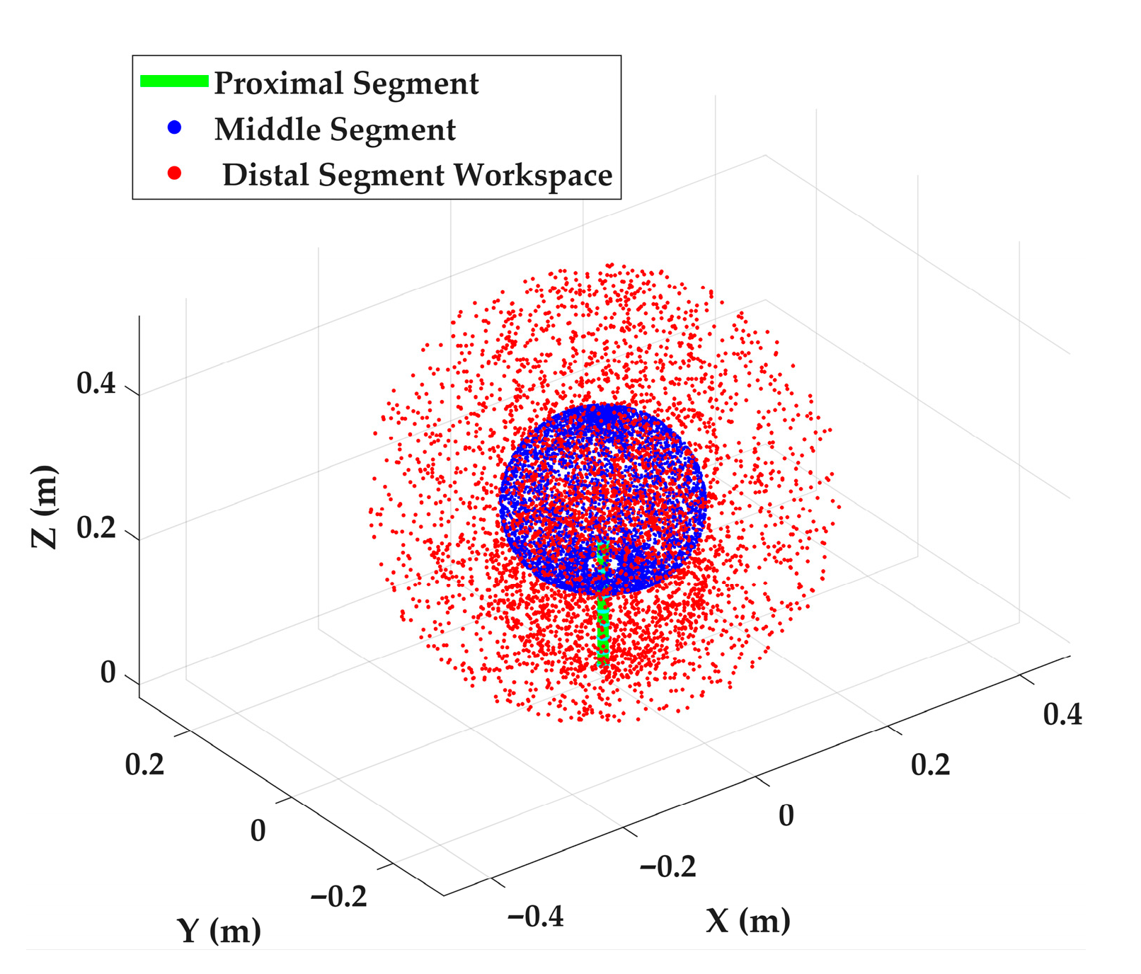
Building upon the workspace analysis of the single-segment continuum robot, with only the initial pose of the proximal segment fixed and incorporating coordinated motion of the middle and distal segments, the multi-segment workspace simulation is completed by sampling 50,000 points. As visualized in Figure 14, the blue point cloud represents the set of end-point positions of the middle segment, while the red point cloud generated through spatial expansion of this set constitutes the compound workspace of the two-segment robot. This methodology facilitates direct extension for workspace analysis of continuum robots with more segments.

4.3. Kinematics-Based Master–Slave Control

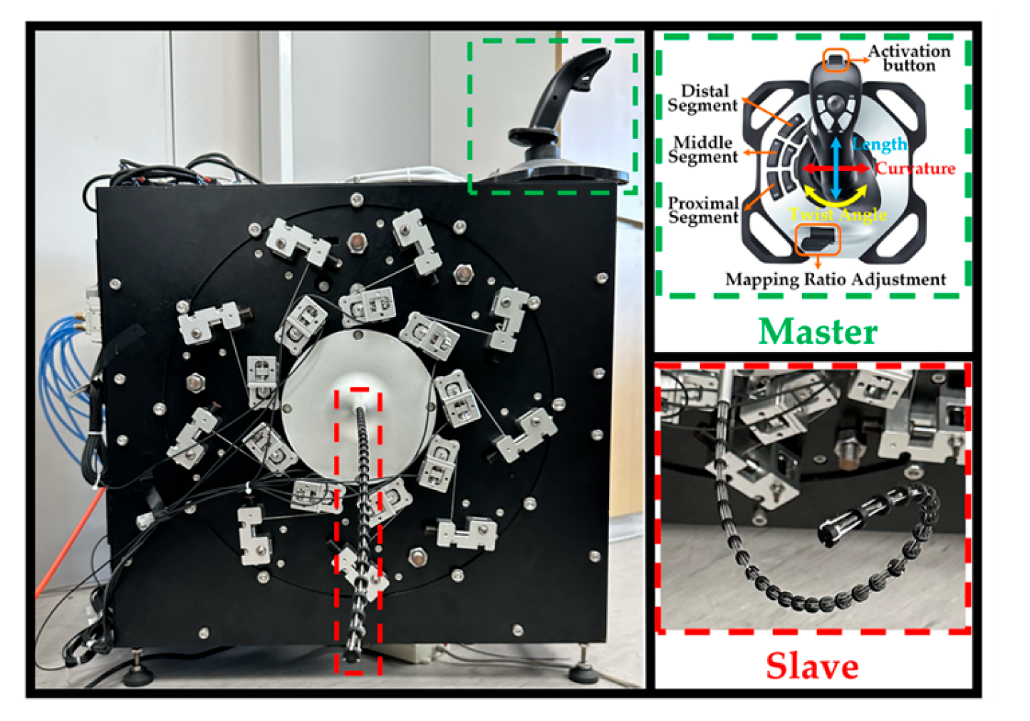
To enable the inspection of aero-engine internal blades using the UHAR-TC robot, this study designed a master–slave control strategy based on the kinematic model, thereby achieving the robot’s inspection motion operation. A Logitech G Extreme 3D Pro joystick was adopted as the master device, establishing a heterogeneous master–slave mapping relationship. This strategy enables the operator to control the robot (slave) via the joystick (master). The master–slave mapping relationship is illustrated in Figure 15, where the three-degree-of-freedom joystick corresponds to the configuration space parameters of a single-segment continuum robot, thus enabling shape change in an individual segment. Switching between controlled segments is realized via additional buttons on the joystick.
Given the discrepancy between the workspaces of the master and slave devices, if an absolute mapping approach is adopted—whereby the absolute position of the joystick is directly mapped to the absolute parameter values of the robot’s joints—it would result in the slave device being unable to obtain sufficient motion space across different inspection scenarios. Conversely, an incremental mapping approach is not constrained by the master’s workspace. This method maps the positional changes in the master device to the slave, requiring only that the slave’s workspace meets the task demands. An independent mapping ratio is preconfigured for each degree of freedom of the flight joystick, enabling control of the slave device’s larger motion range within the master device’s relatively small workspace. To further enhance adaptability to varying task scenarios, the global mapping ratios can be dynamically adjusted using the levers on the joystick. The master control commands output for the slave are consolidated into a command queue, establishing data transmission between the master and slave. Since the master’s sampling frequency typically exceeds the slave’s control frequency, to avoid control latency and conflicts, the control inputs retrieved by the slave from the queue undergo timestamp comparison with the current time. The system responds only to the operator’s most recent commands within a defined time window. The master’s control commands are processed by the slave’s controller to derive the current control parameters for the robot’s joints, thereby actuating the robot’s motion.

4.4. Configuration Space Controller with Decoupling and Tension Compensation

4.4.1. Kinematic Decoupling Method

To address the issue of mutual motion interference between segments caused by driving tendon path coupling in multi-segment continuum robots, a kinematic decoupling method is proposed.
In the actuation space of the continuum robot, the total length of each driving tendon is denoted as q , where q p r o x i m a l represents the lengths of driving tendons located in the proximal segment, q m i d d l e represents the lengths of driving tendons located in the middle segment, and q d i s t a l represents the lengths of driving tendons located in the distal segment. Therefore, the length of each driving tendon can be expressed as
q = [ q 1,2 , 3 p r o x i m a l q 4,5 , 6 p r o x i m a l q 7,8 , 9 p r o x i m a l ] + [ q 1,2 , 3 m i d d l e q 4,5 , 6 m i d d l e 0 ] + [ q 1,2 , 3 d i s t a l 0 0 ]
Here, tendons 1, 2, and 3 actuate the distal segment; tendons 4, 5, and 6 actuate the middle segment; and tendons 7, 8, and 9 actuate the proximal segment.
According to the mapping relationship from the configuration space to the actuation space for a single-segment continuum robot, i.e., the function f q − C − 1 , the effective lengths of the driving tendons within each segment can be obtained as
{ q 7,8 , 9 p r o x i m a l = f q − C − 1 ( L 1 , κ 1 , ϕ 1 ) q 4,5 , 6 m i d d l e = f q − C − 1 ( L 2 , κ 2 , ϕ 2 ) q 1,2 , 3 d i s t a l = f q − C − 1 ( L 3 , κ 3 , ϕ 3 )
Since the effective tendon lengths within each segment passively adapt to the configuration parameters of their respective segment, they cannot be directly obtained via the already derived function f q − C − 1 . However, it is noted that the mapping function from the actuation space to the configuration space, f q − C , is derived based on a predefined coordinate frame. Since rotating the coordinate frame only alters the bending plane angle of the central backbone relative to that frame, without changing the absolute values of arc length and curvature, the following relationships can be established:
{ q 4,5 , 6 p r o x i m a l = f q − C − 1 ( L 1 , κ 1 , ϕ 1 − 40 ° ) q 1,2 , 3 p r o x i m a l = f q − C − 1 ( L 1 , κ 1 , ϕ 1 − 80 ° ) q 1,2 , 3 m i d d l e = f q − C − 1 ( L 2 , κ 2 , ϕ 2 − 40 ° )
Substituting Equations (12) and (13) into (11), the lengths of all driving tendons, q m u l t i , can therefore be expressed as
q m u l t i = [ f q − C − 1 ( L 1 , κ 1 , ϕ 1 − 80 ° ) f q − C − 1 ( L 1 , κ 1 , ϕ 1 − 40 ° ) f q − C − 1 ( L 1 , κ 1 , ϕ 1 ) ] + [ f q − C − 1 ( L 2 , κ 2 , ϕ 2 − 40 ° ) f q − C − 1 ( L 2 , κ 2 , ϕ 2 ) 0 ] + [ f q − C − 1 ( L 3 , κ 3 , ϕ 3 ) 0 0 ]
Rearranging terms yields
q m u l t i = [ f q − C − 1 ( L 1 , κ 1 , ϕ 1 − 80 ° ) + f q − C − 1 ( L 2 , κ 2 , ϕ 2 − 40 ° ) + f q − C − 1 ( L 3 , κ 3 , ϕ 3 ) f q − C − 1 ( L 1 , κ 1 , ϕ 1 − 40 ° ) + f q − C − 1 ( L 2 , κ 2 , ϕ 2 ) f q − C − 1 ( L 1 , κ 1 , ϕ 1 ) ]
Since the inverse kinematics solution provides the Expression (11) from the configuration space to the actuation space, the differential kinematics form between the single-segment actuation space and the configuration space can be obtained:
q ˙ = [ ∂ f 1 ∂ L single ∂ f 1 ∂ κ single ∂ f 1 ∂ ϕ single ∂ f 2 ∂ L single ∂ f 2 ∂ κ single ∂ f 2 ∂ ϕ single ∂ f 3 ∂ L single ∂ f 3 ∂ κ single ∂ f 3 ∂ ϕ single ] C ˙ single
where l i = f i ( L single , κ single , ϕ single , ) ( i = 1,2 , 3 ) , and the solution of the Jacobian matrix is given as follows:
J q − C − 1 = [ ∂ f 1 ∂ L single ∂ f 2 ∂ L single ∂ f 3 ∂ L single ∂ f 1 ∂ κ single ∂ f 2 ∂ κ single ∂ f 3 ∂ κ single ∂ f 1 ∂ ϕ single ∂ f 2 ∂ ϕ single ∂ f 3 ∂ ϕ single ]
This expression is only applicable when the curvature of the central backbone is not 0. For the special case where the curvature of the central backbone is 0, it is only necessary to evaluate the limit of the expression.
l i m κ single → 0 J q − C − 1 = [ 1 − d ( L single − n h ) sin ϕ single 0 1 − d ( L single − n h ) sin ( ϕ single + π 3 ) 0 1 d ( L single − n h ) cos ( ϕ single + π 3 ) 0 ]
Therefore, based on the Jacobian expression of a single segment, the decoupled inverse kinematics expression (Equation (14)) can be transformed into its differential form:
J s − 1 = [ J q − C − 1 ( L 1 , κ 1 , ϕ 1 − 80 ° ) J q − C − 1 ( L 2 , κ 2 , ϕ 2 − 40 ° ) J q − C − 1 ( L 3 , κ 3 , ϕ 3 ) J q − C − 1 ( L 1 , κ 1 , ϕ 1 − 40 ° ) J q − C − 1 ( L 2 , κ 2 , ϕ 2 ) 0 J q − C − 1 ( L 1 , κ 1 , ϕ 1 ) 0 0 ]
where J q − C − 1 is the inverse Jacobian mapping from the configuration space to the actuation space for a single segment, achieving active compensation for other segments during configuration changes in the given segment.
Its differential form is
q ˙ m u l t i = J s − 1 C ˙
where C ˙ = [ L ˙ 1 , κ ˙ 1 , ϕ ˙ 1 , L ˙ 2 , κ ˙ 2 , ϕ ˙ 2 , L ˙ 3 , κ ˙ 3 , ϕ ˙ 3 ] T is the rate of change in the given configuration space. Since the tendon-guiding disk contains nine tendon-guiding holes uniformly distributed on its circumference, adjacent tendon-guiding holes are spaced 40° apart.

4.4.2. Driving Tendon Tension Compensation Controller Design

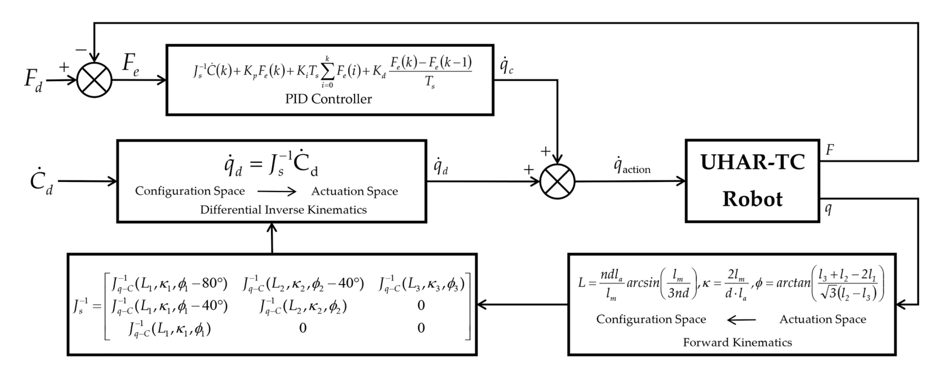
Using only a kinematic decoupling-based open-loop control approach is prone to inducing driving tendon slackness, which in turn leads to motion error accumulation and force transmission discontinuity. To address this limitation, this paper designs a driving tendon tension compensation mechanism as shown in Figure 16. This mechanism establishes a configuration space controller with driving tendon tension compensation based on a PID controller. By adjusting the proportional, integral, and derivative parameters, it can effectively compensate for mechanical factors not considered in the kinematic model under closed-loop control. Even in resource-constrained embedded system environments, it can meet the practical requirements of robot motion control.
Configuration control involves managing the deformation process of each segment by maintaining the tension state of the driving tendons, thereby improving the accuracy of forward kinematic calculations and subsequently enhancing the precision of differential inverse kinematic computations. The rate of change in configuration space parameters, acquired from the joystick, is processed through the differential inverse kinematic expression to solve for the motion rate q ˙ d of each driving tendon. A PID controller then calculates the compensation rate q ˙ c for each driving tendon based on its tension error. Finally, this is converted into the speed q ˙ a c t i o n of each driving tendon to achieve the motion of the continuum robot. The feedforward control law for driving tendon tension compensation is
q ˙ c ( k ) = J s − 1 C ˙ d ( k ) + K p F e ( k ) + K i T s ∑ i = 0 k F e ( i ) + K d F e ( k ) − F e ( k − 1 ) T s
Here, T s denotes the sampling interval, C ˙ d ( k ) represents the desired rate of change in the configuration space of the continuum robot at the k time step, q ˙ c ( k ) is the actual motion velocity of each driving tendon at the k time step, F e ( k ) = F d ( k ) − F ( k ) signifies the cable tension error, F ( k ) is the actual tension in each driving tendon at the k time step, F d ( k ) is the desired tension in each driving tendon at the k time step, and F d is the preset tension threshold vector (accounting for path-dependent coupling friction, with the highest threshold distally and the lowest proximally). K p , K i , and K d are the parameter matrices for the proportional, integral, and derivative terms of the PID controller, respectively. The controller implements a selective compensation strategy: it applies PID control solely to the easily slackened drive cables on the non-active side, while compensation is disabled for the drive cables on the active side (primary drive cables) to avoid interference with normal deformation. Through stable teleoperated control, the target configuration can be progressively achieved.

4.4.3. Coordinated Control Strategy for Extension and Bending Motions

The experimental prototype in this study adopts a master–slave teleoperation control mode, in which the extension and bending motions of the continuum robot body are controlled separately. The operator remotely guides the robot based on real-time images acquired by the distal borescope. When the target inspection area is not centered in the field of view, the operator uses the joystick to sequentially bend one or more of the three segments to adjust the tip pose and bring the target into the center. Once the target is centered, the operator independently controls the extension or retraction of the robot to approach the surface to be inspected. During this process, to maintain the pre-established bending configuration, the nine driving tendons simultaneously follow the extension or retraction of the central backbone by the same distance while the pneumatic grippers actuate the backbone motion. This ensures that the bending angles and curvatures of each segment remain substantially unchanged, achieving a coordinated control logic in which extension does not alter the bending shape.

5. Experimental Verification

Since the robot adopts a master–slave teleoperation control mode, in which the operator guides the motion using a joystick, the trajectory depends on human operation rather than on high-precision repeated positioning. Therefore, the verification focus of this study is not on quantitatively evaluating the repeat positioning accuracy but on assessing whether the robot can successfully access the confined spaces of simulated compressor and turbine blades and obtain clear inspection images under manual control, thereby validating the feasibility of the overall scheme.

5.1. Experimental Setup

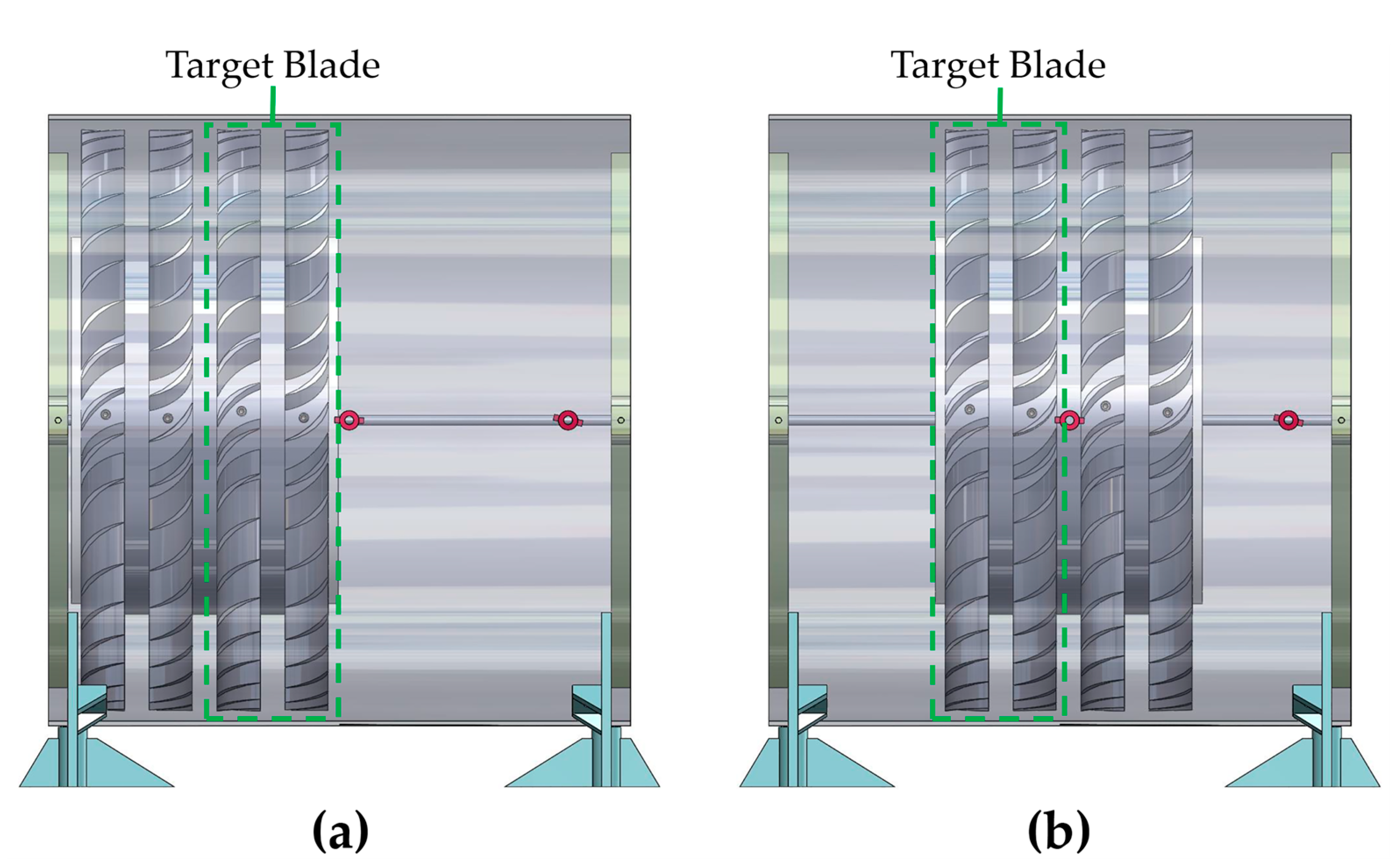
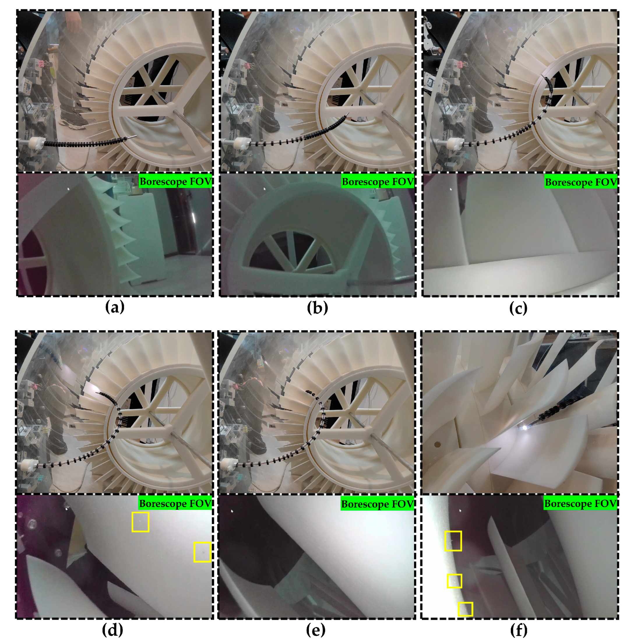
In order to validate the effectiveness of the configuration space control method based on kinematic decoupling and tendon tension compensation and to replicate the test environment of complex and confined spaces inside an aero-engine, an integrated coupled simulation test platform replicating dual scenarios (compressor and turbine blade inspection) was constructed (Figure 17). The platform incorporates four-stage blade rows, with each row mounted to rotate about the central axis and each individual blade fixed at a 50-degree angle relative to that axis. This parameter configuration aligns with the characteristics of actual engine blade arrangements, simulating the blade gap constraints and spatial pose limitations encountered during robotic inspection. This design effectively reproduces the spatial constraint characteristics encountered during actual inspections of turbine and compressor blades.
As shown in Figure 17a, the blade sets are positioned at the far left of the platform to simulate the turbine blade inspection scenario. The UHAR-TC robot enters the platform through a 9 mm-diameter inspection port located on the right side (310 mm from the blade under inspection), maneuvers leftward to reach the target blade, and performs the borescope inspection. As illustrated in Figure 17b, the blade sets are relocated to the central region of the platform to simulate the compressor blade inspection scenario. The UHAR-TC robot enters through an inspection port on the left side, executes a left turn, and subsequently conducts the borescope inspection on the target blade.
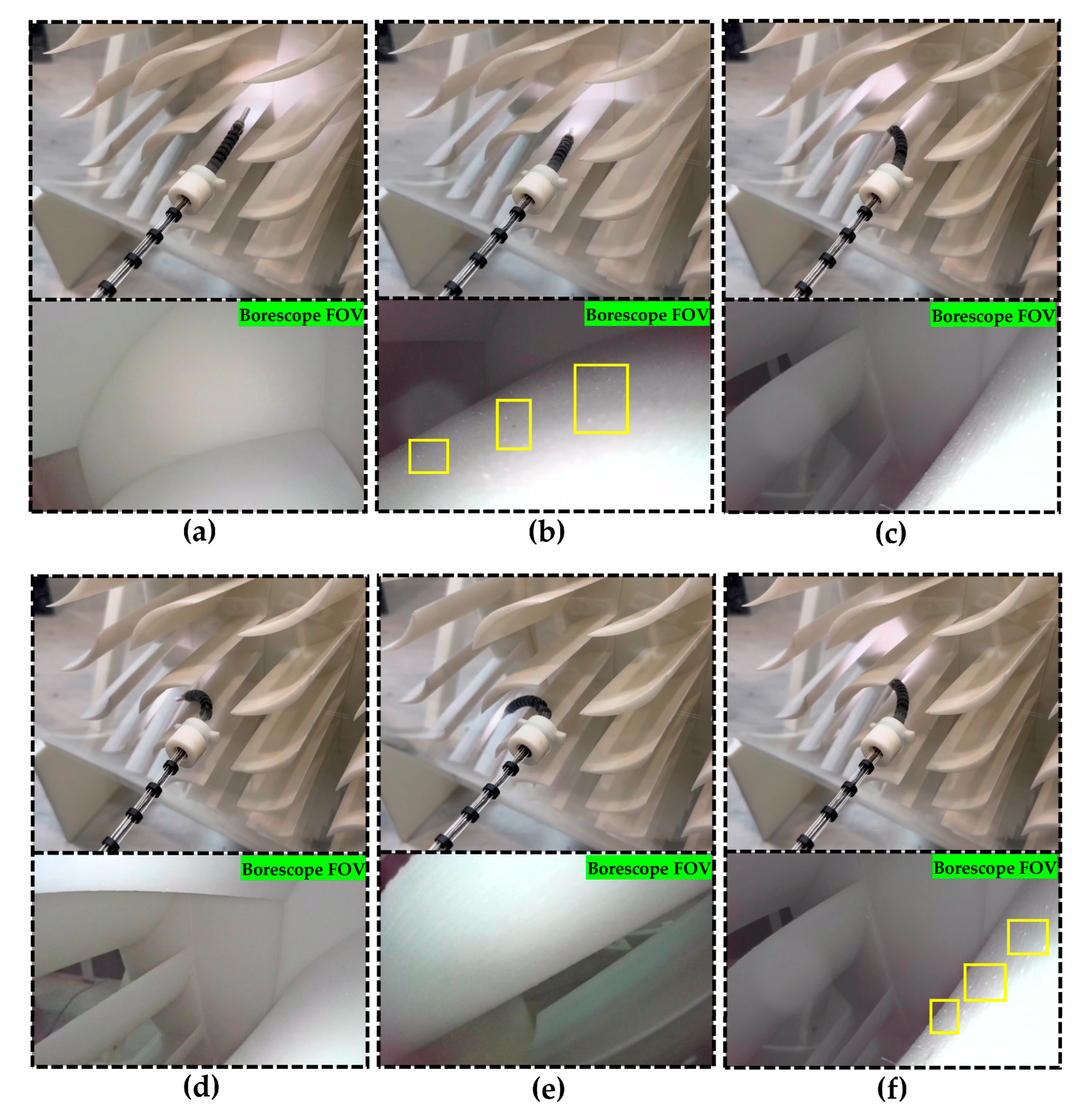
All experiments were conducted at room temperature (approximately 25 °C). Prior to testing, both the robot prototype and the simulated inspection environment were placed on the ground, with the UHAR-TC robot body kept in a horizontally contracted state to enable its front end to quickly align with and enter the side inspection port (9 mm in diameter) of the simulated environment. To accommodate possible variations in the position of the inspection port in actual engines, the initial placement of the entire robot system could be adjusted to roughly align the UHAR-TC body with the axis of the inspection port, thereby adapting to different entry orientations. A total of ten independent trials were performed for both the simulated turbine and compressor blade inspection scenarios. In all trials, the robot successfully captured clear images of the simulated blades using the distal borescope. Figure 18 and Figure 19 each present a representative complete experimental process from one of these trials.
It should be noted that although these controlled experiments reproduced the typical geometric constraints of aero-engine internals, they did not include extreme environmental factors such as high temperature or oil mist. Therefore, the current results should be regarded as a proof of concept under idealized laboratory conditions, and further validation of the robot’s robustness and adaptability in real engine environments is necessary.

5.2. Inspection Experiment for Simulated Turbine Blades

The results of the turbine blade borescope inspection experiment are presented in Figure 18. In the initial phase (Figure 18a), the robot was constrained in contraction and could only achieve slight bending for fine-tuning the borescope camera’s field of view (FOV) at its tip in order to determine the initial motion direction towards the first-stage blade. Subsequently, the proximal actuation segment elongated and bent towards the first-stage blade, bringing the lateral blade into the FOV (Figure 18b). When the elongation of the proximal segment approaches its limit, a kinematic decoupling strategy is employed to control the elongation of the intermediate segment (Figure 18c). This prevents interference from multi-segment drive coupling, thereby advancing the endoscopic camera closer to the primary blade. Through the coordinated elongation of the proximal and middle actuation segments, the robot tip traversed an axial distance of 310 mm, achieving preliminary positioning relative to the target blade. Subsequently, the configuration of the proximal and middle segments was then adjusted via the configuration space control strategy based on kinematic decoupling and driving tendon tension compensation (Figure 18d). During this phase, the tendon tension compensation mechanism maintained cable tautness through PID closed-loop regulation to prevent motion hysteresis induced by slackness, thereby guiding the tip-mounted borescope camera to complete the inspection of the first-stage blade. The image captured by the borescope camera in Figure 18d reveals the burrs (inside the yellow box) on the blade under inspection. To perform an inspection on the second-stage blade while maintaining a stable configuration of the proximal and middle segments, the distal segment was actuated to elongate and bend. This motion was executed via decoupled control, which ensured the stability of the proximal and middle segment configurations by driving the distal segment independently. This enabled the robot tip to traverse the gap between the first-stage blades and approach the surface of the second-stage blade (Figure 18e). Finally, through adjustments of the tip pose, the borescope camera successfully captured an image of the burrs (inside the yellow box) on the surface of the second-stage blade (Figure 18f).
During the experiments, the kinematic decoupling strategy effectively avoided motion interference caused by multi-segment driving tendon path coupling. Meanwhile, the tendon tension compensation mechanism, through PID closed-loop regulation, maintained the tautness of all driving tendons, thereby preventing motion hysteresis or force transmission interruptions induced by tendon slackness. This ensured the stability of complex configuration control.

5.3. Inspection Experiment for Simulated Compressor Blade

The experimental procedure for the compressor blade borescope inspection followed the same control framework as that employed for the turbine blade inspection. Benefiting from the inherently compact spatial constraints of this scenario, the tip-mounted borescope camera could directly approach the blade under inspection without relying on elongation motions of the proximal or middle segments. In this context, the kinematic decoupling strategy confined the motion to the distal segment alone, preventing any passive motion of the proximal and middle segments. Experimental results demonstrated that multi-stage blade inspection tasks could be accomplished solely by manipulating the distal segment (Figure 19). In the initial state, the borescope camera could already clearly observe the edge profiles of two-stage blades located on both sides of the inspection port (Figure 19a). The operator maneuvered the borescope camera via the joystick to the vicinity of the surface of the first-stage blade on the left side (Figure 19b). During this maneuver, the tendon tension compensation mechanism suppressed tension fluctuations, ensuring smoothness of the tip motion, which led to the successful capture of a clear image of its surface burrs (inside the yellow box). While traversing the gap between the left-side first-stage blades (Figure 19c), adjusting the configuration of the continuum robot enabled comprehensive inspection of this blade and simultaneously provided an initial field of view (FOV) of the left-side second-stage blade, thereby informing subsequent path selection (Figure 19d). Upon reaching the vicinity of the left-side second-stage blade (Figure 19e), with the distal segment not yet reaching its elongation limit, further control through kinematic decoupling and tension compensation allowed its elongation, which not only achieved motion of the distal segment but also maintained tendon tautness. This brought the camera closer to the blade surface, resulting in the acquisition of a clear image of blade surface burrs (inside the yellow box of Figure 19f).
Kinematic decoupling ensures independent motion of the distal segment without interference from passive deformation of the proximal and middle segments, thereby meeting the requirements for navigating narrow gaps. Concurrently, tension compensation control effectively guarantees the faithful replication of the continuum robot’s intended configuration.

6. Discussion

6.1. Core Innovations and Performance Breakthroughs

The UHAR-TC robot presented in this paper, through the synergistic design of its nested central backbone and pneumatic hand-over-hand drive mechanism, successfully achieves a high aspect ratio of 63.75:1 and a long-stroke telescopic motion of 350 mm. This performance metric significantly surpasses the typical aspect ratio limit of below 50 for existing self-supporting continuum robots. Experimental validation demonstrates that the robot can traverse a φ9 mm inspection port and achieve positioning and high-definition imaging of multi-stage blades over an axial distance of 310 mm. This represents a substantial advancement in addressing the core challenges of “accessibility” and “visibility” within the extremely confined spaces of aero-engines. Its innovativeness lies not only in the ultra-high aspect ratio but also in achieving active, controllable telescopic motion under this aspect ratio, a capability absent in traditional industrial borescopes and most existing continuum robots.

6.2. Comparative Analysis with Existing Technologies

To contextualize the performance advancements of the UHAR-TC robot, a quantitative comparison is conducted with a state-of-the-art continuum robot developed by the Continuum Robotics Laboratory at the University of Toronto [7], which shares a similar tendon-driven, extensible-section design philosophy. As detailed in Table 5, while both robots maintain a comparable outer diameter of approximately 8 mm, the UHAR-TC robot demonstrates a significant performance leap. Through its innovative nested central backbone and pneumatic hand-over-hand drive mechanism, the UHAR-TC achieves an aspect ratio of 63.75:1, a substantial increase from the 23.6:1 ratio of the comparative model. Furthermore, its effective axial telescopic stroke is extended to 350 mm, nearly three times the 120 mm stroke of the reference robot. This direct comparison underscores that the core innovation of the UHAR-TC lies in achieving extreme slenderness and long-range extension without compromising its compact cross-sectional profile.

6.3. Effectiveness and Limitations of the Control Strategy

The kinematics-decoupling-based master–slave control strategy proved effective in mitigating the inherent motion coupling in multi-segment tendon-driven systems. During the dual-scenario experiments involving both turbine and compressor blades, the robot demonstrated the ability for independent segment elongation and coordinated bending, validating the practicality of the control algorithm. However, it must be noted that the current control strategy primarily relies on a kinematic model based on the constant curvature assumption. In complex contact environments, the friction between the driving tendons and tendon-guiding disks increases with the movement stroke, which makes tension compensation more challenging. Although the integrated tendon tension feedback mechanism provides a certain level of compensation, the future integration of real-time shape sensing is expected to enable higher-precision closed-loop shape control, further enhancing robustness in complex contact environments.

6.4. Engineering Applicability and Future Challenges

The coupled dual-scenario test platform constructed in this study effectively replicates the typical spatial constraints of aero-engine compressor and turbine sections, enhancing the persuasiveness of the experimental validation. The robot’s successful task completion in both distinct scenarios demonstrates its potential for engineering applications. Nonetheless, limitations remain and need to be addressed in future work. Firstly, the current prototype uses Ni-Ti alloy tubes for the central backbone, which, despite excellent superelasticity, have limited stiffness, constraining the payload capacity and affecting the integration of heavier multi-modal sensors (e.g., eddy current probes). Secondly, the sequential actuation logic of the pneumatic grippers means only one segment can telescope at any given time, which might not be optimal for all motion trajectories. Most critically, the experiments were conducted in a simulated laboratory environment, failing to capture extreme factors such as high temperature, oil mist, and vibrations present in real engine environments. The long-term reliability of the drive system and materials under these extreme conditions is a key issue that must be verified before practical application.

7. Conclusions

This paper presents a novel ultra-high-aspect-ratio telescopic continuum robot (UHAR-TC robot) designed for in situ aero-engine borescope inspection. The robot achieves a maximum aspect ratio of 63.75:1 and a telescopic stroke of 310 mm, enabling it to enter through a 9 mm-diameter inspection port and inspect multi-stage turbine and compressor blades. Experimental validation on a dual-scenario simulated testbed demonstrated that, under manual teleoperation, the robot successfully completed inspection tasks for both turbine and compressor blades and captured clear images of surface burrs. By integrating a configuration-space control strategy that combines kinematic decoupling with tendon tension compensation, the issues of multi-segment coupling and tendon slack were effectively mitigated.
Despite the achievements presented above, this study has certain limitations. First, all experiments were conducted at room temperature, without considering the effects of the high-temperature environment within the engine on the mechanical properties of the Ni-Ti alloy tubes. Second, the robot’s load capacity is currently limited, allowing it to carry only a miniature camera. Future work will focus on: (1) exploring high-temperature-resistant materials and cooling strategies; (2) integrating force sensors and visual servoing to enable more autonomous and robust inspection; and (3) developing interchangeable end-effectors to expand its maintenance functionalities.


Author Contributions

Conceptualization, Y.H. and D.H.; methodology, D.H. and Y.H.; software, W.Z. and D.H.; validation, D.H., N.S. and Y.W.; investigation, Y.W., N.S. and D.H.; writing—original draft preparation, D.H. and N.S.; writing—review and editing, Y.H. and D.H. All authors have read and agreed to the published version of the manuscript.

Funding

This research received no external funding.

Data Availability Statement

Data are contained within the article.

Conflicts of Interest

The authors declare no conflicts of interest.

References

  1. Zou, F. Review of aero-engine defect detection technology. In Proceedings of the 2020 IEEE 4th Information Technology, Networking, Electronic and Automation Control Conference (ITNEC), Chongqing, China, 12–14 June 2020; IEEE: New York, NY, USA; Volume 1, pp. 1524–1527. [CrossRef] [Scilit]
  2. Gail, J.; Kruse, F.; Gu-Stoppel, S.; Schmedemann, O.; Leder, G.; Reinert, W.; Wysocki, L.; Burmeister, N.; Ratzmann, L.; Giese, T.; et al. Advancements in aircraft engine inspection: A mems-based 3D measuring borescope. Aerospace 2025, 12, 419. [Google Scholar] [CrossRef] [Scilit]
  3. Troncoso, D.A.; Robles-Linares, J.A.; Russo, M.; Elbanna, M.A.; Wild, S.; Dong, X.; Mohammad, A.; Kell, J.; Norton, A.D.; Axinte, D. A continuum robot for remote applications: From industrial to medical surgery with slender continuum robots. IEEE Robot. Autom. Mag. 2022, 30, 94–105. [Google Scholar] [CrossRef] [Scilit]
  4. Zhong, W.; Huang, Y.; Hong, D.; Shao, N. Design and control of an ultra-slender push-pull multisection continuum manipulator for in-situ inspection of aeroengine. In Proceedings of the 2024 IEEE/RSJ International Conference on Intelligent Robots and Systems (IROS), Abu Dhabi, United Arab Emirates, 14–18 October 2024; pp. 11394–11401. [Google Scholar] [CrossRef] [Scilit]
  5. Dupont, P.E.; Simaan, N.; Choset, H.; Rucker, C. Continuum robots for medical interventions. Proc. IEEE 2022, 110, 847–870. [Google Scholar] [CrossRef] [Scilit]
  6. Nwafor, C.J.; Girerd, C.; Laurent, G.J.; Morimoto, T.K.; Rabenorosoa, K. Design and fabrication of concentric tube robots: A survey. IEEE Trans. Robot. 2023, 39, 2510–2528. [Google Scholar] [CrossRef] [Scilit]
  7. Amanov, E.; Nguyen, T.-D.; Burgner-Kahrs, J. Tendon-driven continuum robots with extensible sections—A model-based evaluation of path-following motions. Int. J. Robot. Res. 2021, 40, 7–23. [Google Scholar] [CrossRef] [Scilit]
  8. Zhang, W. Research on Time-Optimal Trajectory Planning and Constant Force Control of Aero-Engine Blade Grinding Robot, Master’s Thesis, Hebei University of Technology, Tianjin, China, 2022.
  9. Ben, A.H.; Jovančević, I.; Orteu, J.J.; Brèthes, L. Automatic inspection of aeronautical mechanical assemblies by matching the 3D CAD model and real 2D images. J. Imaging 2019, 5, 81. [Google Scholar] [CrossRef] [Scilit] [PubMed]
  10. Bogue, R. Climbing robots: Recent research and emerging applications. Ind. Robot Int. J. Robot. Res. Appl. 2019, 46, 721–727. [Google Scholar] [CrossRef] [Scilit]
  11. Ramalingam, B.; Manuel, V.H.; Elara, M.R.; Vengadesh, A.; Lakshmanan, A.K.; Ilyas, M.; James, T.J.Y. Visual inspection of the aircraft surface using a teleoperated reconfigurable climbing robot and enhanced deep learning technique. Int. J. Aerosp. Eng. 2019, 2019, 5137139. [Google Scholar] [CrossRef] [Scilit]
  12. Wu, X.; Wang, C.; Hua, S. Predictor-based adaptive feedback control for a class of systems with time delay and its application to an aircraft skin inspection robot. IET Control Theory Appl. 2020, 14, 763–773. [Google Scholar] [CrossRef] [Scilit]
  13. Andrikopoulos, G.; Papadimitriou, A.; Brusell, A.; Nikolakopoulos, G. On model-based adhesion control of a vortex climbing robot. In Proceedings of the 2019 IEEE/RSJ International Conference on Intelligent Robots and Systems (IROS), Macau, China, 3–8 November 2019; pp. 1460–1465. [Google Scholar] [CrossRef] [Scilit]
  14. Shang, J.; Sattar, T.; Chen, S.; Bridge, B. Design of a climbing robot for inspecting aircraft wings and fuselage. Ind. Robot. Int. J. 2007, 34, 495–502. [Google Scholar] [CrossRef] [Scilit]
  15. Zhuge, J.; Zeng, S.; Xu, J.; Wu, J. Mechanical structure design and motion analysis for wall-climbing robot of aircraft skin detection. Mech. Sci. Technol. Aerosp. Eng. 2021, 40, 641–648. [Google Scholar] [CrossRef]
  16. De Rivaz, S.D.; Goldberg, B.; Doshi, N.; Jayaram, K.; Zhou, J.; Wood, R.J. Inverted and vertical climbing of a quadrupedal microrobot using electroadhesion. Sci. Robot. 2018, 3, eaau3038. [Google Scholar] [CrossRef] [Scilit] [PubMed]
  17. Shang, K. Design and Analysis of Miniature Crawling Robot for Detection of Aeroengine, Master’s Thesis, Harbin Institute of Technology, Harbin, China, 2023.
  18. Dong, X.; Wang, M.; Mohammad, A.; Ba, W.; Russo, M.; Norton, A.; Kell, J.; Axinte, D. Continuum robots collaborate for safe manipulation of high-temperature flame to enable repairs in challenging environments. IEEE/ASME Trans. Mechatron. 2022, 27, 4217–4220. [Google Scholar] [CrossRef] [Scilit]
  19. Russo, M.; Sadati, S.M.H.; Dong, X.; Mohammad, A.; Walker, I.D.; Bergeles, C.; Xu, K.; Axinte, D.A. Continuum robots: An overview. Adv. Intell. Syst. 2023, 5, 2200367. [Google Scholar] [CrossRef] [Scilit]
  20. Robinson, G.; Davies, J.B.C. Continuum robots-a state of the art. In Proceedings of the 1999 IEEE International Conference on Robotics and Automation (Cat. No. 99CH36288C), Detroit, MI, USA, 10–15 May 1999; IEEE: New York, NY, USA; Volume 4, pp. 2849–2854. [CrossRef] [Scilit]
  21. McMahan, W.; Jones, B.A.; Walker, I.D. Design and implementation of a multi-section continuum robot: Air-octor. In Proceedings of the 2005 IEEE/RSJ International Conference on Intelligent Robots and Systems, Edmonton, AB, Canada, 2–6 August 2005; pp. 2578–2585. [Google Scholar] [CrossRef] [Scilit]
  22. Murphy, R.J.; Kutzer, M.D.M.; Segreti, S.M.; Lucas, B.C.; Armand, M. Design and kinematic characterization of a surgical manipulator with a focus on treating osteolysis. Robotica 2014, 32, 835–850. [Google Scholar] [CrossRef] [Scilit]
  23. Rucker, D.C.; Jones, B.A.; Webster, R.J., III. A geometrically exact model for externally loaded concentric-tube continuum robots. IEEE Trans. Robot. 2010, 26, 769–780. [Google Scholar] [CrossRef] [Scilit]
  24. Xu, K.; Zhao, J.; Fu, M. Development of the SJTU unfoldable robotic system (SURS) for single port laparoscopy. IEEE/ASME Trans. Mechatron. 2014, 20, 2133–2145. [Google Scholar] [CrossRef] [Scilit]
  25. Laschi, C.; Mazzolai, B.; Cianchetti, M. Soft robotics: Technologies and systems pushing the boundaries of robot abilities. Sci. Robot. 2016, 1, eaah3690. [Google Scholar] [CrossRef] [Scilit]
  26. Falkenhahn, V.; Hildebrandt, A.; Neumann, R.; Sawodny, O. Dynamic control of the bionic handling assistant. IEEE/ASME Trans. Mechatron. 2016, 22, 6–17. [Google Scholar] [CrossRef] [Scilit]
  27. Kaleel, D.; Clement, B.; Althoefer, K. Modelling of buoyancy based actuation of an inflatable underwater soft robot. In Proceedings of the Annual Conference Towards Autonomous Robotic Systems, London, UK, 21-23 August 2024; Springer Nature: Cham, Switzerland, 2024; pp. 242–253. [Google Scholar] [CrossRef] [Scilit]
  28. Webster, R.J., III; Jones, B.A. Design and kinematic modeling of constant curvature continuum robots: A review. Int. J. Robot. Res. 2010, 29, 1661–1683. [Google Scholar] [CrossRef] [Scilit]
  29. Trivedi, D.; Lotfi, A.; Rahn, C.D. Geometrically exact models for soft robotic manipulators. IEEE Trans. Robot. 2008, 24, 773–780. [Google Scholar] [CrossRef] [Scilit]
  30. Rao, P.; Peyron, Q.; Lilge, S.; Burgner-Kahrs, J. How to model tendon-driven continuum robots and benchmark modelling performance. Front. Robot. AI 2021, 7, 630245. [Google Scholar] [CrossRef] [Scilit] [PubMed]
  31. Gravagne, I.A.; Walker, I.D. Manipulability, force, and compliance analysis for planar continuum manipulators. IEEE Trans. Robot. Autom. 2002, 18, 263–273. [Google Scholar] [CrossRef] [Scilit] [PubMed]
  32. Penning, R.S.; Jung, J.; Ferrier, N.J.; Zinn, M.R. An evaluation of closed-loop control options for continuum manipulators. In Proceedings of the 2012 IEEE International Conference on Robotics and Automation, Saint Paul, MN, USA, 14–18 May 2012; pp. 5392–5397. [Google Scholar] [CrossRef] [Scilit]
  33. Gallentine, J.; Wooten, M.B.; Thielen, M.; Walker, I.D.; Speck, T.; Niklas, K. Searching and intertwining: Climbing plants and GrowBots. Front. Robot. AI 2020, 7, 118. [Google Scholar] [CrossRef] [Scilit]
  34. Mohammad, A.; Russo, M.; Fang, Y.; Dong, X.; Axinte, D.; Kell, J. An efficient follow-the-leader strategy for continuum robot navigation and coiling. IEEE Robot. Autom. Lett. 2021, 6, 7493–7500. [Google Scholar] [CrossRef] [Scilit]
  35. Wang, M.; Palmer, D.; Dong, X.; Alatorre, D.; Axinte, D.; Norton, A. Design and development of a slender dual-structure continuum robot for in-situ aeroengine repair. In Proceedings of the 2018 IEEE/RSJ International Conference on Intelligent Robots and Systems (IROS), Madrid, Spain, 1–5 October 2018; pp. 5648–5653. [Google Scholar] [CrossRef] [Scilit]
  36. Dong, X.; Palmer, D.; Axinte, D.; Kell, J. In-situ repair/maintenance with a continuum robotic machine tool in confined space. J. Manuf. Process. 2019, 38, 313–318. [Google Scholar] [CrossRef] [Scilit]
  37. Wang, Y.; Ju, F.; Cao, Y.; Yun, Y.; Wang, Y.; Bai, D.; Chen, B. An aero-engine inspection continuum robot with tactile sensor based on EIT for exploration and navigation in unknown environment. In Proceedings of the 2019 IEEE/ASME International Conference on Advanced Intelligent Mechatronics (AIM), Hong Kong, China, 8–12 July 2019; pp. 1157–1162. [Google Scholar] [CrossRef] [Scilit]
  38. Yang, Z.; Yang, L.; Sun, Y.; Chen, X. Comprehensive kinetostatic modeling and morphology characterization of cable-driven continuum robots for in-situ aero-engine maintenance. Front. Mech. Eng. 2023, 18, 40. [Google Scholar] [CrossRef] [Scilit]
  39. Zhou, B.; Yu, S.; Li, S.; Zi, B.; Zhu, W. Active disturbance rejection control for vibration suppression of a dual-arm cooperative rigid-flexible coupling hoisting robot. IEEE Trans. Ind. Electron. 2026, in press. [Google Scholar] [CrossRef] [Scilit]
  40. Ye, N.; Bai, S.; Zhang, D.; Yang, M.; Wang, F. Adaptive kriging-assisted single loop approach for reliability-based design optimization via inverse dimension reduction method. Acta Mech. Sin. 2025. Available online: https://www.sciengine.com/doi/10.1007/s10409-025-25614-x (accessed on 21 January 2026).
  41. Liu, X.; An, D.; Chen, Y.; Tang, G.; Yuan, X.; Gu, H.; You, B. Geometric skill learning paradigm for cellular space robots: Achieving cross-task and cross-configuration generalization. Aerosp. Sci. Technol. 2026, 173, 111783. [Google Scholar] [CrossRef] [Scilit]
  42. Zhong, W. Design and Control of an Ultra-Slender Continuum Robot for in-situ Inspection of Aeroengine, Master’s Thesis, Beijing Institute of Technology, Beijing, China, 2023.
Figure 1. UHAR-TC robot.
Aerospace 13 00291 g001
Figure 2. UHAR-TC robot body: (a) schematic diagram of a single active bending segment structure; (b) schematic diagram of the tendon-guiding disk structure; (c) schematic diagram of the connection between tendon-guiding disks and springs; (d) schematic diagram of the UHAR-TC robot body structure with 3 active bending segments; and (e) physical prototype of the UHAR-TC robot body described.
Aerospace 13 00291 g002
Figure 3. Actuation system of the UHAR-TC robot: (a) guide base; (b) tension sensing unit; (c) tendon actuation unit; (d) telescopic actuation unit; (e) integrated assembly of the actuation system.
Aerospace 13 00291 g003
Figure 4. Guide base: (a) partial enlarged view of composite guide tube; (b) partial enlarged view of connection zone between composite guide tube, wire guide disk, and central backbone guide tube; (c) integrated assembly.
Aerospace 13 00291 g004
Figure 5. Tension sensing unit: (a) integrated assembly; and (b) sectional view.
Aerospace 13 00291 g005
Figure 6. Tendon actuation unit: (a) integrated assembly; and (b) sectional view.
Aerospace 13 00291 g006
Figure 7. Telescopic actuation unit.
Aerospace 13 00291 g007
Figure 8. Schematic diagram of the constant curvature assumption.
Aerospace 13 00291 g008
Figure 9. Mapping relationships among multiple spaces.
Aerospace 13 00291 g009
Figure 10. Geometric relationship between the tendon-guiding disks and the driving tendons.
Aerospace 13 00291 g010
Figure 11. Verification of forward and inverse kinematics between actuation and configuration spaces: (a) before-bending shape; (b) after-bending shape; (c) before-twisting shape; (d) after-twisting shape.
Aerospace 13 00291 g011
Figure 12. Schematic diagram of the single-segment continuum robot workspace.
Aerospace 13 00291 g012
Figure 13. End effector poses determined by three continuum segments in different configurations: (a) fixed twist angles ( ϕ 1 = π / 2 ,   ϕ 2 = π ,   ϕ 3     =   3 π / 2 ) with varying curvatures (from κ   =   4 m − 1   t o     κ   =   9 m − 1 )   ; (b) fixed curvatures ( κ 1     =   3 m − 1 ,     κ 2   =   4 m − 1 ,   κ 3   =   5 m − 1 ) with varying twist angle (from ϕ   =   π / 20   t o   ϕ   =   3 π /10).
Aerospace 13 00291 g013
Figure 14. Schematic diagram of the multi-segment continuum robot workspace.
Aerospace 13 00291 g014
Figure 15. Master–slave control system. Where q d represents the desired parameter in the actuation space, and C d represents the desired parameter in the configuration space.
Aerospace 13 00291 g015
Figure 16. The configuration space control diagram is based on driving tendon tension compensation, where l a = l 1 + l 2 + l 3 and l m = l 1 2 + l 2 2 + l 3 2 − l 1 l 2 − l 2 l 3 − l 3 l 1 .
Aerospace 13 00291 g016
Figure 17. Coupled simulation test platform for duo aero-engine blade inspection scenarios: (a) simulating turbine blade borescope inspection; and (b) simulating compressor blade borescope inspection.
Aerospace 13 00291 g017
Figure 18. Simulated turbine blade borescope inspection experiment: (a) initial positioning; (b) adjusting the FOV; (c) approaching the target blade; (d) imaging of the first-stage blade surface; (e) moving to the second-stage blade; (f) imaging of the second-stage blade surface.
Aerospace 13 00291 g018
Figure 19. Simulated compressor blade borescope inspection experiment: (a) initial positioning; (b) imaging the left-side first-stage blade surface; (c) crossing through the first-stage blade gap; (d) adjusting the FOV; (e) approaching the second-stage blade; (f) imaging the left-side second-stage blade surface.
Aerospace 13 00291 g019
Table 1. Parameters of Ni-Ti alloy tubes for each segment. Unit: mm.
ParametersSmall TubeMedium TubeLarge Tube
Inner Diameter0.601.101.32
Outer Diameter1.001.221.44
Length975678380
Table 2. Parameters of tendon-guiding disks for each segment. Unit: mm.
SegmentsDisks d 1 d 2 d 3 d 4 l 1 l 2 l 3 l 4 l 5
DistalEnd2.71.30.56111.50.503
Freely Movable2.71.05/ *111013
MiddleEnd2.71.571.0510.51.50.50.53
Freely Movable2.71.32/ *111013
ProximalEnd2.71.841.3210.51.50.50.53
Freely Movable2.71.59/ *111013
* There is no such parameter.
Table 3. Control logic of pneumatic grippers.
Motion
Object
Motion
Phase
Large-Tube
Gripper
Medium-Tube
Gripper
Small-Tube GripperFloating Gripperlarge-Tube StateMedium-Tube StateSmall-Tube State
Large-Tube
Actuation
Actuation StrokeOpenOpenOpenCloseActive
Control
Follow
Motion
Follow
Motion
Return
Stroke
CloseCloseCloseOpenStaticStaticStatic
Medium-Tube
Actuation
Actuation StrokeCloseOpenCloseCloseStaticActive
Control
Follow
Motion
Return
Stroke
CloseCloseCloseOpenStaticStaticStatic
Small-Tube
Actuation
Actuation StrokeCloseCloseOpenCloseStaticStaticActive
Control
Return
Stroke
CloseCloseCloseOpenStaticStaticStatic
Static State/ *CloseCloseCloseOpenStaticStaticStatic
* There is no motion state.
Table 4. Comparison of numerical solution results for inverse kinematics.
Tolerance
Error
Computed Configuration Parameters
(m−1; rad; m−1; rad; m−1; rad)
IterationError
10−1[1.9100, −0.0285, 5.0289, 1.5968, 8.0008, 3.1486]T70.012966
10−3[1.9894, 0.0506, 4.8006, 1.5209, 7.8995, 3.1447]T260.000993
10−4[1.9977, −0.0034, 5.0136, 1.5736, 8.0070, 3.1421]T510.000097
Table 5. Comparison of key specifications between the UHAR-TC robot and advanced robots of the same type.
SpecificationUHAR-TC RobotContinuum Robot of
University of Toronto [7]
Application scenarioAero-engine borescope
inspection
Minimally invasive surgery and industrial inspection
Aspect ratio63.75:123.6:1
Maximum telescopic stroke350 mm120 mm
Total length of the robot body510 mm165 mm
Outer diameter of the
robot body
8 mm7 mm
Extension/retraction drive method of the robot bodyPneumatic hand-over-hand drive mechanismMotor-driven ball screw
actuation
Method for equidistant distribution of tendon-guiding disksSpaced by springsSpaced by permanent
magnets
Disclaimer/Publisher’s Note: The statements, opinions and data contained in all publications are solely those of the individual author(s) and contributor(s) and not of MDPI and/or the editor(s). MDPI and/or the editor(s) disclaim responsibility for any injury to people or property resulting from any ideas, methods, instructions or products referred to in the content.