


Abstract
The center of mass is a key parameter characterizing the mass distribution of an object, and its measurement holds significant importance in high-tech fields such as aerospace, the defense industry, and precision manufacturing. With modern engineering demanding ever-increasing spacecraft flight stability, control precision, and precision measurement requirements, the accuracy, efficiency, and adaptability of center of mass measurement have also become research hotspots. This paper systematically reviews current mainstream measurement techniques, including static and dynamic methods, while analyzing their respective advantages and sources of error. By comparing Chinese and non-Chinese achievements in center of mass measurement equipment development and engineering applications, it identifies existing challenges and issues in the field and outlines future trends in center of mass measurement technology.
1. Introduction
The center of mass (COM) is one of the key parameters characterizing the spatial distribution of mass in a rigid body [1]. Its position not only determines the response characteristics of an object under force but also serves as the fundamental basis for constructing dynamic models, performing motion control, and conducting structural optimization design. In aerospace systems, the accuracy, repeatability, and stability of center of mass measurements [2,3] are of paramount importance. The location of the center of mass is critical regardless of whether it lies within or outside the physical boundaries of an object, as it directly impacts the static and dynamic stability of the aircraft, the effectiveness of attitude control, and the distribution of structural loads. A center of mass positioned externally may indicate asymmetric mass distribution or the presence of deployable structures, leading to increased control forces, unexpected torques, and potential mission risks. Furthermore, distinguishing between an object’s geometric center and its center of mass is critical. The geometric center is determined solely by the structure’s shape and symmetry, while the center of mass depends on the distribution of mass within the object. In aerospace systems, mass distribution is rarely uniform due to the presence of fuel, avionics, structural reinforcements, and deployable subsystems. Therefore, precisely determining the center of mass location is essential for safe and reliable flight operations.
Taking spacecraft as an example, their in-orbit attitude stabilization control systems rely heavily on precise knowledge of the overall center of mass position [4]. Even millimeter-level deviations can amplify control torque errors, potentially triggering trajectory drift, abrupt attitude changes, and other issues [5]. Ultimately, this may cause spacecraft yaw, control system instability, and directly impact flight safety and mission precision [6]. Particularly in space science missions such as gravity recovery and climate experiment (GRACE), challenging minisatellite payload (CHAMP), next generation gravity mission (NGGM), and deep-space gravitational wave detection missions, errors in the center of mass position directly compromise the accuracy of scientific payload observations. This becomes a critical system bottleneck determining mission sensitivity and observational precision. In addition, the center of mass of GNSS satellites is particularly crucial for determining precise orbital information. Therefore, center of mass measurement is not only a fundamental measurement task but also a crucial safeguard for system safety and performance [7].
Early ground center-of-gravity measurements primarily relied on the principle of static equilibrium, with typical methods including the three-point support method and composite suspension method. While these techniques are well-established, they generally suffer from high dependence on manual labor, lengthy testing cycles, and poor adaptability to complex structures. These limitations make it difficult to meet the contemporary trends in spacecraft development toward larger sizes, greater complexity, higher reliability, and faster delivery. Furthermore, when dealing with non-standard shapes, flexible connection components, and high-sensitivity payloads, traditional methods also demonstrate insufficient capabilities in repeatability [8] and systematic error control [9].
Currently, both Chinese and non-Chinese research institutions and scholars have achieved substantial results in center of mass measurement methods and their system integration [10]. Internationally, notable achievements have been made in establishing fundamental physical models, designing high-precision sensing systems, and innovating spatial measurement techniques. This has led to the emergence of various center-of-gravity testing platforms spearheaded by organizations such as NASA and Space Electronics. Domestically, China has also achieved numerous breakthroughs in recent years regarding the engineering application and system integration optimization of center-of-gravity measurement. Particularly in fields like rocket munitions, launch vehicle telemetry and control, and aircraft delivery testing, a series of center-of-gravity detection systems tailored to domestic requirements have been developed.
Especially for future next-generation gravity measurement missions and precision space science observation platforms, ground-based center of mass measurement technology faces increasingly stringent challenges: including sub-millimeter or even nanometer-level accuracy requirements, ensuring measurement repeatability during multiple attitude adjustment processes, and enhancing non-contact measurement and intelligent decision-making capabilities. Therefore, systematically summarizing the development trajectory of current center of mass measurement methods, mapping core technological pathways, and analyzing their future trends in space science missions holds significant importance for driving breakthroughs in related technologies and facilitating their engineering implementation.
To this end, this paper reviews the evolution and trends of ground-based center of mass measurement technology in the aerospace field. Section 2 revisits the fundamental principles and methodological frameworks of traditional center of mass measurement, then traces the developmental trajectory of modern measurement methods from perspectives including static and dynamic measurements. Section 3 discusses different technical approaches by conducting an in-depth comparison of key technological pathways and research characteristics in center of mass measurement technology between China and non-Chinese entities. Section 4 explores the critical requirements and future development directions for measurement systems against the backdrop of next-generation gravity measurement and deep-space missions. Finally, Section 5 summarizes the paper and presents insights into the future development of center of mass measurement technology, aiming to provide theoretical support and methodological references for related research and engineering practice.
2. Common Methods for Center of Mass Measurement
Theoretical calculations of the center of mass indicate that for structures with uniform density and geometry, the center of mass lies at the geometric center of the cross-section and can be directly determined using symmetry. However, aerospace systems are typically composed of non-uniform or composite cross-sections where material density, thickness, or internal components vary along the structure. In such cases, the center of mass must be calculated by integrating the mass distribution or by summing the discrete masses of different sub-sections. In this paper, COM refers to the mass centroid determined solely by the mass distribution of a rigid body. Center of gravity (COG) refers to the point where the resultant gravitational force acts. For a rigid body in a uniform gravitational field, COM and COG coincide; however, in microgravity or non-uniform gravitational fields, the distinction may become relevant. Therefore, COM is used as the primary term throughout this paper, and COG is mentioned only when the discussion explicitly involves gravity-related effects. Regarding experimental methods, center of mass measurement methods [11] are broadly categorized into static measurement methods [12,13] and dynamic measurement methods [14]. As shown in Figure 1, static measurement methods primarily include the suspension method [15], multi-point weighing method [16,17,18], and unbalanced moment method. Dynamic measurement methods include the compound pendulum method [19], the moment of inertia method [1], and the rotational balancing method [1]. Additionally, newer approaches [20,21] exist, such as dynamic analysis of model motion [22] and video capture methods [23,24].
Figure 1.
Classification diagram of centroid measurement methods.
2.1. Static Measurement
2.1.1. Suspension Method
Suspension method [15] as shown in Figure 2, this method involves suspending the test specimen to allow it to hang freely. Based on the characteristic that the resultant force acting on the specimen is directed toward its center of gravity, the position of the center of gravity is determined by measuring the intersection point of the extended lines of the suspension wires at two different orientations. This measurement method is simple in principle and easy to operate. However, it is primarily used for measuring thin plates and smaller objects. For objects with complex shapes, it is difficult to accurately locate the intersection point of the two lines, making it challenging to improve measurement accuracy.
Figure 2.
Schematic diagram of the suspension method [15].
2.1.2. Multi-Point Weighing Method
Multi-point weighing method [25] as shown in Figure 3 utilizes multiple load cells (3 or 4) to jointly support the test specimen. Based on the load cell outputs and their positions, the method calculates the center of gravity location using the principle of static moment equilibrium. A single measurement provides both the two-dimensional coordinates of the test specimen’s center of gravity and its mass.
Figure 3.
Schematic diagram of multi-point weighing method [25].
This method features a simple structure, ease of operation, simultaneous measurement of mass and center of gravity, and high measurement safety [26,27]. It is frequently applied in the measurement of large-scale aircraft [28,29,30]. However, in scenarios demanding high measurement accuracy—such as hypersonic vehicles and intercontinental ballistic missiles—measurement precision is constrained by factors including lateral forces introduced by sensor support structures and positioning errors arising from mechanical positioning.
2.1.3. Unbalanced Moment Method
As shown in Figure 4, the unbalanced moment method [31,32] is a technique that calculates the center of gravity by measuring the unbalanced moment at the support point of the test specimen using mechanical structures such as knife edges. The measurement accuracy of this method depends on the precision of the pressure sensors and is also closely related to the sharpness of the support point. To enhance measurement accuracy, spherical air-bearing supports can be employed. The unbalanced moment method is widely used in scenarios requiring high measurement accuracy and involving small test specimens. However, for large-scale aircraft measurements, the sharpness of the cutting edge significantly impacts results: excessively sharp edges reduce load-bearing capacity, while overly blunt edges compromise sensitivity. Additionally, the limited load-bearing capacity of air-bearing supports constrains the application of this method in large-scale aircraft measurements.
Figure 4.
Schematic diagram of the unbalanced moment method [1].
2.2. Dynamic Measurement
2.2.1. Rotational Balancing Method
The rotational balancing method [1] employs a dynamic balancing machine as a dynamic measurement technique. As shown in Figure 5, the test specimen is rotated around its axis by an electric motor. During rotation, force sensors at both bearing ends continuously measure force variations in real time. The acquired data is then processed to determine the specimen’s center of mass.
Figure 5.
Schematic diagram of the rotational balancing method [1].
The advantage of this measurement method is its ability to simultaneously determine both the moment of inertia and the center of gravity. However, the operational process is relatively cumbersome, and the computational procedures are quite complex. Furthermore, test specimens with wings—such as irregularly shaped aircraft or solar panels—are difficult to mount securely. Additionally, the influence of air resistance during rotation limits improvements in measurement accuracy. For large-scale vehicles like intercontinental ballistic missiles and launch vehicles, challenges such as rotational drive systems and specimen safety concerns are unavoidable.
2.2.2. Moment of Inertia Method
The method of rotational inertia [1] employs the parallel axis theorem. As shown in Figure 6, when the test specimen is placed at different positions on the measuring platform, distinct rotational inertia values can be obtained, thereby enabling the calculation of the specimen’s center of mass. To measure the center of mass in two dimensions, the test specimen must be repositioned at least twice, totaling three positions including the initial placement. When the repositioning distance is small, high rotational inertia measurement sensitivity is required. Conversely, large repositioning distances introduce significant measurement errors due to off-center loading. Consequently, this method is rarely applied.
Figure 6.
Schematic diagram of the moment of inertia method [1].
2.2.3. Compound Pendulum Method
The pendulum method [19] utilizes the pendulum period to calculate the position of the center of gravity. As shown in Figure 7, the test specimen is secured to a support tray. Both the specimen and tray are simultaneously tilted away from the vertical by a certain angle and released to swing freely. The initial swing angle is typically less than 5°. By measuring the swing period, the motion equation is solved to determine the center of gravity of the test specimen.
Figure 7.
Schematic diagram of the compound pendulum method [19].
This method features a simple structure, but when measuring large-scale aircraft, it imposes high demands on the strength of the pendulum. Furthermore, due to their substantial volume, large-scale aircraft experience significant air damping during oscillation, making it challenging to achieve high measurement accuracy.
2.2.4. Three-Wire Pendulum Method
The suspended-wire torsion pendulum method [33,34,35] is primarily categorized into three-wire and five-wire pendulums based on the number of suspension wires [36,37], with the three-wire pendulum [36] being more common. As shown in Figure 8, this is a schematic diagram of the three-wire pendulum. The test specimen is suspended by three wires and allowed to freely twist. An initial angle must be specified before twisting. By measuring the twisting period of the test specimen, the position of its center of mass can be calculated.
Figure 8.
Schematic diagram of the three-wire pendulum method [36].
This measurement method is low-cost and easy to implement, capable of simultaneously measuring rotational inertia, and has found widespread application in practice. However, it presents several challenges for larger objects: the test specimen may exhibit both oscillation and twisting simultaneously, making it difficult to accurately measure the motion period; large specimens experience significant air damping, and safety hazards may arise during measurement; additionally, this method requires separate measurement of the specimen’s mass.
2.2.5. Five-Wire Pendulum Method
The five-wire pendulum method [38] determines the center of gravity position by analyzing an object’s vibrational response, serving as a high-precision measurement technique (Figure 9). It finds extensive application in aerospace, mechanical, and structural engineering fields, demonstrating significant value particularly for measuring the center of gravity of complex-shaped, high-mass objects. Through precise measurement and data analysis, the five-wire pendulum method provides accurate center of gravity position data for various engineering tasks [39].
Figure 9.
Schematic diagram of the five-line twist method [38].
For three-dimensional objects, particularly in fields such as aerospace, pendulum techniques are commonly employed to determine the spatial displacement of their centers of mass. The core principle of such techniques involves deriving the spatial coordinates of the center of mass relative to a reference axis or point by analyzing the dynamic characteristics of the object as it oscillates within a gravitational field or elastic system. This measurement method can determine the center of mass position to a precision exceeding approximately 1 μm [40].
Despite the advantages of high precision and broad adaptability offered by the pendulum method, its practical application still faces challenges, such as symmetry errors in support structures, modeling compensation for system damping, and control of environmental disturbances [41,42]. Consequently, current research is actively incorporating multi-sensor information fusion, machine learning-assisted modeling, and error compensation algorithms to further enhance the practicality and stability of pendulum-based center of mass measurement techniques in complex engineering environments.
2.2.6. Speed Modulation Technology
Conklin proposed a novel technique for measuring the center of mass of a sphere in 2006, termed velocity modulation [43,44] (Figure 10). In velocity modulation, a sphere rolls along a set of parallel tracks, converting the spectral information of its center of mass displacement into rolling-rate frequency. The sphere’s trajectory is optically measured by recording its transit time through five optical gates. This technique can determine the sphere’s center of mass position with state-of-the-art precision at the 100 nm level.
Figure 10.
Schematic diagram of the speed modulation technology [43,44].
2.3. Characteristics and Analysis
In summary, various center of mass measurement techniques possess distinct advantages and limitations in terms of application scenarios, measurement accuracy, system complexity, and adaptability. To facilitate comparative analysis, this study systematically summarizes the key characteristics of several typical center of mass measurement methods in Table 1, covering dimensions such as measurement accuracy and primary features. This table provides an intuitive overview of each method’s suitability across different engineering contexts, offering a reference basis for subsequent system selection and optimization design.
Table 1.
Comparison of centroid measurement methods and characteristics.
3. Engineering Applications of Center of Mass Measurement in the Aerospace
High-precision measurement of the center of gravity holds significant engineering value in the aerospace field, finding extensive application in critical areas such as aircraft structural design, mass distribution control, attitude stability analysis, and orbital accuracy assessment. As spacecraft evolve toward larger and modular designs, and aircraft performance demands increasingly focus on high maneuverability and low radar cross-section, center-of-gravity measurement technology faces heightened challenges in measurement accuracy, real-time responsiveness, and system reliability.
High-precision mission platforms such as gravity satellites and scientific experiment satellites impose extremely stringent requirements on center of mass parameters. For example, the GRACE gravity satellite [45,46], jointly launched by NASA and the German Aerospace Center (DLR) in 2002, primarily aimed to measure variations in Earth’s gravitational field [47,48]. This mission critically relies on precise inter-satellite distance measurements, demanding a strict requirement for satellite center of mass positional offset less than 100 μm. The GRACE Follow-On (GRACE-FO) satellite launched in 2018 [49,50], building upon the GRACE mission, further incorporates laser interferometers to optimize the Satellite-to-Satellite Tracking–Interferometric (SST-II) mode [51,52].
Additionally, the Gravity Probe B (GP-B) mission [53]—a joint space experiment conducted by NASA and Stanford University—stands as one of the most precise drag-free satellites to date. Its design objective is to overcome the accuracy limitations of ground-based experiments, enabling ultra-high-sensitivity observations of general relativity effects in a microgravity environment. However, accurately determining the center of mass (COM) position of the GP-B satellite proved extremely challenging due to factors such as structural manufacturing tolerances, non-uniform material density distribution, and component assembly deviations. For such drag-free control satellites, COM offset not only impacts attitude control precision but also increases propellant consumption, becoming a critical factor limiting mission lifespan.
Thus, center of mass measurement plays an increasingly vital role in spacecraft design, attitude adjustment, and orbit maintenance. This chapter systematically reviews typical application scenarios of current center of mass measurement technologies in the aerospace field, comprehensively presenting their development status in both engineering practice and cutting-edge research.
3.1. Progress in Engineering Research Institutions
During spacecraft development and in-orbit operations, center of mass measurement technology plays a critical role. After entering orbit, spacecraft operate in a near-zero-atmospheric-drag environment where flight control precision is intrinsically linked to center of mass accuracy. Precise measurement of the center of mass position is fundamental to ensuring the successful execution of spacecraft attitude control, orbital maneuvers, and other critical operations.An overview of spacecraft center-of-mass measurements at research institutions is shown in Figure 11.
Figure 11.
Overview of center of mass measurement for spacecraft in research institutions.
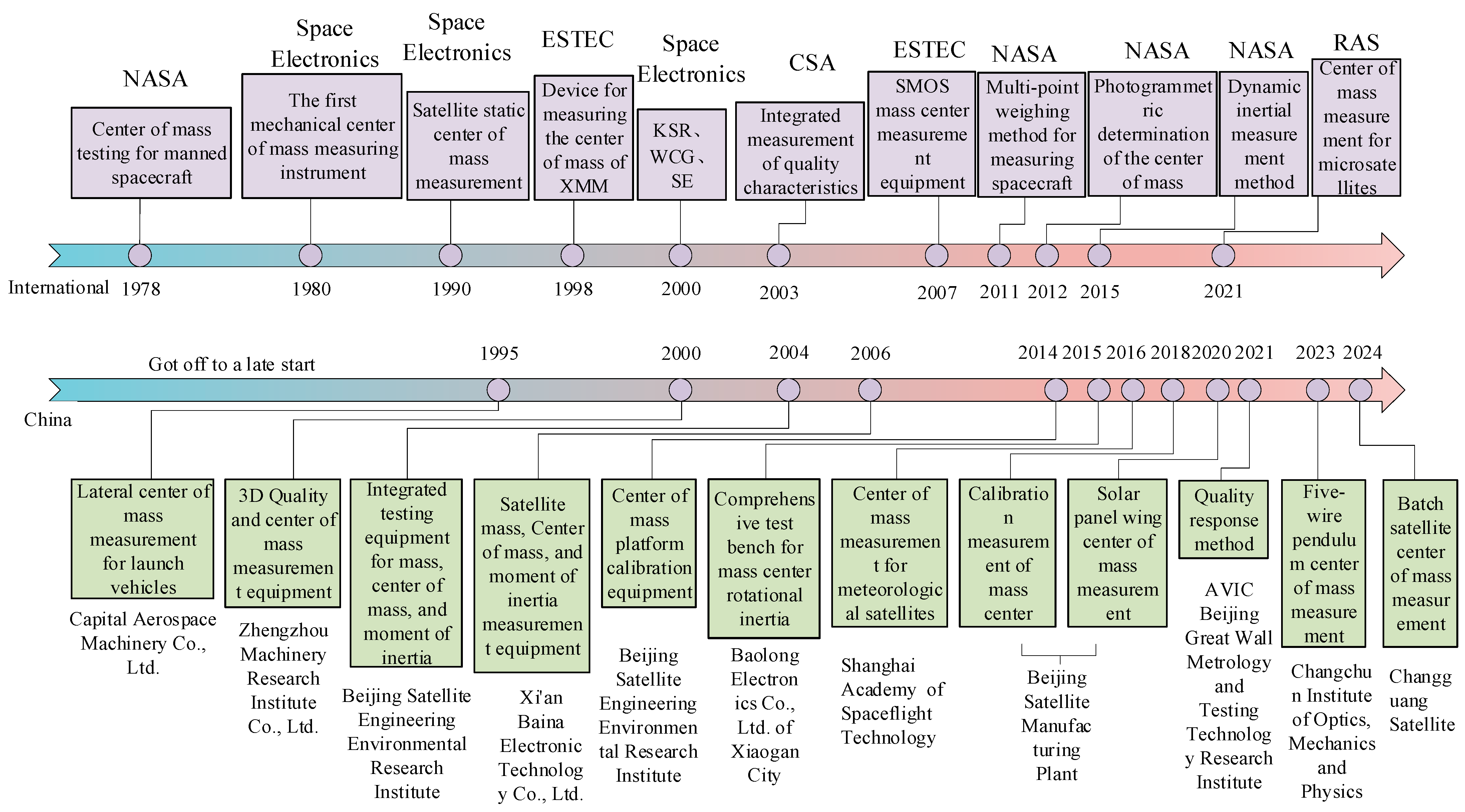
Internationally, the most representative companies [54,55,56] and research institutions in this field are Space Electronics [57,58,59] and National Aeronautics and Space Administration (NASA) [60]. Founded in 1959, Space Electronics is the world’s largest manufacturer of mass characteristic measurement instruments, achieving global leadership in the production of equipment for measuring parameters such as center of gravity. In the 1980s, the company developed the first mechanical center of gravity measurement instrument. During the 1990s, it applied large L-shaped brackets to static satellite center of gravity measurements, with a load capacity ranging from approximately 13.61 kg to 4535.92 kg. Centroid measurement instruments developed in the early 21st century achieved a weighing capacity of approximately 9979.03 kg. The KSR series of measurement instruments, as shown in Figure 12, enables simultaneous measurement of mass, centroid, and inertia on a single device. This reduces the number of times the product needs to be clamped during measurement and shortens the measurement time to one-third of the original duration. The KSR center of mass measurement system achieves a measurement accuracy of 0.02 mm. This equipment employs the unbalanced moment method for center-of-gravity measurement. As long as the dimensions of the test object fall within a specified range, a single KSR device can measure objects of varying sizes. Due to the use of spherical air-bearing technology in the KSR system, it also exhibits excellent overload tolerance [61].
Figure 12.
Physical diagram of the KSR measurement system [61].
Currently, in addition to the KSR series of measuring instruments, Space Electronics Inc. has developed two other series of center-of-gravity measurement equipment: the WCG series, suitable for large-sized, heavy products and employing a multi-point weighing method to measure center-of-gravity parameters; and the SE series, suitable for small products and employing an unbalanced moment method to measure center-of-gravity parameters. For measuring mass characteristics of aerospace vehicles, the WCG measurement system performs well and can be used to measure the center of mass of large spacecraft, as shown in Figure 13. This system employs a multi-point weighing method to measure the center of gravity, meeting the measurement requirements for large-sized vehicles with a capacity range reaching the ton level. However, its measurement accuracy is relatively low, with measurement errors around 1 mm.
Figure 13.
WCG measurement of the center of mass [58].
Among these three series, the SE series measuring instruments offer the highest measurement accuracy. Specifically, the SE8913 series center of mass measuring instrument employs the unbalanced torque method, utilizing a spherical air-bearing as the pivot and a high-precision torque sensor to measure torque. For products with a mass ≤ 30 kg, the SE8913 center of mass measuring platform achieves a measurement accuracy of 0.1 mm (Figure 14).
Figure 14.
SE8913 series high-precision center of mass measurement system [59].
In 1978, NASA had already developed a precise method for measuring the mass and lateral center of gravity of spacecraft [62] (Figure 15). Developed to meet the requirements of the Voyager spacecraft mission, this method could limit the uncertainty of the lateral center of mass for spacecraft systems weighing up to 750 kg to within 1 mm. The method involved using three load cells symmetrically distributed on a turntable relative to the spacecraft’s vertical axis, spaced 120 degrees apart, with six measurements taken for each load cell. These six measurements are performed by cyclically rotating the load cell turntable and spacecraft about the vertical axis of the measurement fixture. This approach eliminates all alignment, leveling, and load cell calibration errors associated with lateral center of mass determination and enables statistical best-fit analysis of the measurement data.
Figure 15.
Overall layout of the mass and center of mass measurement device [62].
By altering the orientation of the test specimen in two different postures, the three-dimensional center of gravity of a spacecraft can be measured. Consequently, the multi-point weighing method is frequently employed to test static parameters such as the mass and center of gravity of manned spacecraft. In 2011, NASA utilized the multi-point weighing method to measure the physical dimensions of a specific model of space capsule, as illustrated in Figure 16.
Figure 16.
On-site measurement of the manned spacecraft [62].
In 2012, NASA proposed a method for measuring the center of mass using multi-camera imaging [60]. As shown in Figure 17, this method involves suspending the test object in different configurations. Three cameras distributed in space simultaneously capture images of the object. By processing multiple sets of photos taken under various suspension conditions, the position of the center of mass is calculated. This method is suitable for large, irregularly shaped objects or those with uniformly distributed external materials. It offers fast measurement speeds and requires no complex mechanical structures. However, its measurement accuracy is relatively low, with deviations from computer simulation analysis results around 30 mm. It remains in the research phase at present.
Figure 17.
Physical diagram of multi-camera imaging method [60].
In 2015, NASA Armstrong Flight Research Center’s Dynamic Inertial Measurement (DIM) method utilized ground-based vibration test apparatus to determine an object’s mass characteristics using frequency response function data. The DIM method has been validated on small test objects but has not yet been successfully validated on large aerospace vehicles. In response, NASA Armstrong Flight Research Center (Edwards, California) conducted mass property tests on the “Iron Bird”, with DIM testing yielding favorable results for center of gravity and moment of inertia measurements [63] (Figure 18).
Figure 18.
X-38 CRV undergoing DIM testing [63].
In addition to U.S. research institutions, the European Space Research and Technology Centre (ESTEC) has developed multiple sets of mass measurement equipment tailored to the characteristics of different spacecraft over the years. As shown in Figure 19a, this is the equipment developed by ESTEC in 1998 for measuring the XMM (X-ray Multi-Mirror spacecraft) [64]. The XMM spacecraft stands 10 m tall, has a diameter exceeding 4 m, and weighs 4 tons. Figure 19b depicts the measurement equipment developed in 2007 for the SMOS (Soil Moisture and Ocean Salinity) spacecraft [65]. Both sets of equipment can measure mass and center of gravity. By comparing the measured values of mass and center of gravity with the design values, serious assembly errors can be detected. However, no technical parameters have been reported.
Figure 19.
Physical image of the mass property measurement device developed by the European Space Agency. (a) Field photos of XMM measurements [64]. (b) Field photos of SMOS measurements [65].
The David Florida Laboratory at the Canadian Space Agency developed a mass characteristic testing apparatus (MRC MK VII-16) for comprehensive integrated measurement of mass properties. Employing dual precision air-bearing technology and utilizing the unbalanced torque method to measure the center of mass, this apparatus achieves a measurement accuracy of 0.1% for test objects ranging from 25 to 2720 kg [66].
In 2021, the Keldysh Institute of Applied Mathematics of the Russian Academy of Sciences [67] proposed a combination of algorithms for two-stage balancing of a microsatellite model. During the first stage, while the model undergoes free, uncontrolled motion, the position of its center of mass relative to the suspension rotation center is estimated based on the known displacement of the balancing payload, along with the components of its inertia tensor. This technique was tested on a Sputnix-designed test bench, achieving an estimated center of mass position accuracy of approximately 10 μm. Table 2 summarizes the primary methods and characteristics employed by various international research institutions.
Table 2.
Status of spacecraft center of mass measurement in international research institutions.
Research on mass center measurement technology in China began in the 1980s, starting relatively late compared to the international community. Key engineering research institutions include: Capital Aerospace Machinery Company (Beijing, China), Zhengzhou Machinery Research Institute Co., Ltd. (Beijing, China), Xi’an Baina Electronic Technology Co., Ltd. (Xi’an, China), Xiaogan Baolong Electronics Co., Ltd. (Leqing, China), and Beijing Satellite Engineering Environmental Research Institute (Beijing, China), among others.
In 1995, Li Shude et al. from the Capital Aerospace Machinery Company (Beijing, China) [68] discussed the process technology of a distributed electronic measurement system for determining the mass and lateral center of gravity of carrier rockets. They provided a brief introduction to the measurement principles, equipment, methods, and accuracy analysis. After calibration and evaluation, this process was applied to measurements on the first, second, and third stages. The rocket successfully placed satellites into orbit during both flight missions [69].
At the end of 2000, Zhengzhou Machinery Research Institute Co., Ltd. (Zhengzhou, China) was established, succeeding the former Zhengzhou Research Institute of Mechanical Science and Technology. Its primary business encompasses research into mass property parameter measurement technology and the development of related equipment [70,71]. Figure 20a shows the company’s multifunctional mass characteristic measurement equipment, capable of measuring multiple parameters including mass, three-dimensional center of gravity, three-dimensional moment of inertia, inertia product, inertia principal axis azimuth, and vertical dynamic balance. It is suitable for measuring test pieces with a mass not exceeding 5000 kg, achieving a mass measurement accuracy of 0.05% and a center of gravity measurement accuracy of 0.05 mm. As shown in Figure 20b, the comprehensive mass characteristic measurement equipment developed by Zhengzhou Machinery Research Institute Co., Ltd. is suitable for cylindrical test pieces with a small length-to-diameter ratio and tail support. It can complete the measurement of mass, three-dimensional center of gravity, and three-dimensional moment of inertia in a single setup. The mass measurement range does not exceed 2000 kg, with a mass measurement accuracy of 0.5% and a center of gravity measurement accuracy of 0.6 mm.
Figure 20.
Actual photo of quality characteristic parameter measurement equipment at Zhengzhou Machinery Research Institute Co., Ltd. (a) Multifunctional quality characteristic measurement equipment [72]. (b) Integrated quality characteristic measurement equipment [72].
In 2006, Xi’an Baina Electronic Technology Co., Ltd. developed a series of testing equipment for key mass characteristic parameters in defense and military industries such as aviation, aerospace, naval vessels, and weaponry. Utilizing the multi-point weighing method, the company created various specifications of mass and center of gravity measurement devices [73]. Figure 21a shows an integrated measurement device developed by the company, featuring an automatic conversion mechanism to switch between mass, center of gravity, and moment of inertia measurement modes. Figure 21b depicts the satellite mass, center of gravity, and moment of inertia measurement device. Satellites are mounted via a flower-shaped plate, enabling simultaneous mass and center of gravity measurements with a single clamping operation. This method employs mechanical positioning of the test specimen relative to the measurement system, achieving a center of gravity measurement uncertainty of 0.7 mm.
Figure 21.
Testing equipment developed by Xi’an Baina Electronic Technology Co., Ltd. (a) Physical diagram of integrated measurement equipment [74]. (b) Physical diagram of center of mass and moment of inertia measurement equipment [74].
Baolong Electronics Co., Ltd. of Xiaogan City has collaborated closely with universities including Huazhong University of Science and Technology and Chongqing University to develop various comprehensive quality characteristic test benches and produce complete sets of equipment [75]. In 2015, the company developed a comprehensive mass characteristic test bench utilizing a manual three-coordinate transfer machine to control product movement, tilting, and rotation. The measurement process requires only a single mounting, reducing human intervention errors associated with re-hoisting and leveling, thereby enhancing measurement efficiency and accuracy. In 2021, the company developed a large-diameter rocket and missile engine mass center test bench integrating the functions of both electronic scales and center-of-gravity platforms. By controlling the telescopic movement of tilting lifting rods, it enables adjustable platform inclination angles. Stepwise measurement of product weight and center-of-gravity projection points during horizontal and inclined states determines the product’s mass center without requiring re-hoisting, achieving high measurement efficiency. Currently, the company’s products are primarily applied in aerospace, aviation, automotive, and other fields, as shown in Figure 22. The mass and center of gravity rotational inertia integrated test bench is suitable for products weighing less than 500 kg, with a mass measurement accuracy of ±0.3% F.S., a center of gravity measurement accuracy of ±0.5 mm, and a rotational inertia measurement accuracy of ±1% F.S. The Satellite Mass Center Measurement Platform is specialized equipment for measuring the mass and center of mass position of satellites. It has a maximum payload capacity of 5000 kg.
Figure 22.
Center of mass testing equipment developed by Xiaogan Baolong Electronics Co., Ltd. (a) Comprehensive test bench for mass center of inertia [76]. (b) Satellite mass center measurement platform [76].
In 2004, technical personnel at the Beijing Satellite Engineering Environmental Research Institute [77], in response to the prevailing state of spacecraft testing and manufacturing capabilities in China, independently developed an integrated testing device combining mass, center of gravity, and moment of inertia measurement functions, along with a coordinate transformation unit designed for use with this integrated device. This system was employed for mass characteristic testing of a specific class of spacecraft, enabling the simultaneous measurement of mass, center of gravity in three directions, moment of inertia around three axes, and inertia product with a single fixture setup. This approach significantly enhanced testing efficiency while reducing safety risks. In 2011, Wang Hongxin et al. [78] from the Beijing Satellite Environment Engineering Research Institute focused on analyzing the structure and principles of spacecraft mass characteristic testing equipment currently used at NASA’s Goddard Space Flight Center and the French Space Agency under the European Space Agency, providing reference for spacecraft mass characteristic testing technicians. In 2014, Chen Mian et al. [79] from the Beijing Satellite Environment Engineering Research Institute proposed that standard weights serve as specialized metrological equipment for calibrating three-point force-measuring mass center platforms, with their mass measurement accuracy directly impacting the platform’s measurement precision. By analyzing the calibration algorithm for mass center platforms and introducing corresponding correction methods, they validated the effectiveness of these approaches through practical application.
In 2016, Dong Yaohai from the Shanghai Academy of Spaceflight Technology [80] introduced the configuration, payload and platform subsystem composition, primary missions, key functions, and performance metrics of China’s second-generation geostationary meteorological satellite, Fengyun-4 (FY-4). The satellite implemented multiple lateral center of mass assurance measures during all phases of assembly. High-precision center of mass measurements (with measurement accuracy better than 0.5 mm) were conducted prior to factory release and before transport to the launch site. This approach minimized lateral center of mass shifts during orbital maneuvers without increasing the satellite’s total mass, thereby reducing disturbance torques to ensure safe repositioning while conserving propellant—effectively extending the satellite’s operational lifespan.
In 2016, Li Nan et al. [81] from the Beijing Great Wall Metrology and Testing Technology Research Institute of AVIC (Beijing, China) reviewed the current status of center of mass measurement and calibration methods worldwide, comparing the advantages and disadvantages of different approaches. In 2018, Li Nan et al. [82] further analyzed the measurement uncertainty of center of mass measurement for rotating bodies based on the multi-point support method. In 2021, Li Nan et al. [83] designed a high-precision center of mass measurement system based on the mass reaction method. They outlined its measurement principles, described the system’s structural composition and measurement methodology, and analyzed experimental data along with its traceability. Results demonstrated that the system achieves high measurement accuracy with a maximum axial measurement uncertainty of 0.05 mm.
In 2018, Yu Rongrong et al. [84] from Beijing Satellite Manufacturing Plant Co., Ltd. (Beijing, China) proposed a high-precision testing method based on mass calibration and center of mass compensation. Through calibration experiments, they obtained the sensor’s calibration coefficients to correct mass measurements, thereby eliminating the impact of weighing sensor nonlinearity on mass measurement results. By precisely measuring product installation errors and analyzing the effects of lateral displacement, tilt angle, and tilt direction on center of mass measurements, an error compensation algorithm was integrated into the software to enable real-time compensation of center of mass results. Additionally, a redundant testing method was proposed, incorporating two sets of measurement units and two industrial control computers to achieve hardware redundancy and enhance system reliability. The mass measurement accuracy of the redundancy-designed mass center measurement device is 0.05% F.S., with mass center measurement accuracy of ±1 mm. Redundancy switching is simple and convenient.
In 2019, Feng Yanjun et al. [85] from the Shanghai Satellite Engineering Research Institute proposed a test plan and data processing method for verifying micro-nano satellite separation technology. Prior to separation tests, mass and center-of-gravity measurements were conducted using three high-precision load cells and a high-flatness platform. The test results provide valuable reference for subsequent separation impact tests in scientific research.
In 2020, Wang Xiaoyang et al. [86] from Beijing Satellite Manufacturing Factory Co., Ltd. (Beijing, China) developed a high-precision, efficient, and automated testing method for solar array panel mass characteristics to address the issues of low measurement accuracy, low measurement efficiency, and outdated measurement techniques in traditional testing methods. Based on the three-point weighing method, the solar array panel’s tilt attitude was adjusted using an attitude adjustment device. The mass and center of gravity were measured by taking the arithmetic mean of multiple readings. Results demonstrated that the proposed method achieved center of gravity measurement accuracy exceeding 0.5 mm, reducing measurement time from 8 h to 40 min.
In 2023, Zhou Cheng et al. [87] from the Shanghai Satellite Equipment Research Institute conducted in-depth research on measurement errors during mass center determination. They derived a theoretical expression for systematic errors in mass center measurement and analyzed the variation patterns of center of mass errors under different parameters. For existing testing equipment, with the installation position and angle of the load cells fixed, experiments were conducted to measure the center of mass of a 2000 kg standard body at different tilt angles. This validated the consistency between the observed longitudinal center of mass measurement error variation and the theoretical analysis.
In 2023, the team led by Wang Zhi at the Changchun Institute of Optics, Mechanics and Physics, Chinese Academy of Sciences [40] designed a five-wire pendulum center of mass measurement apparatus. Using this apparatus, they conducted center of mass measurement experiments on test mass specimens (Figure 23). Based on the free-vibration frequency of the five-wire pendulum measured by an autocollimator, the center of mass and center-of-shape deviations of the test mass samples were determined. Experimental results from multiple measurements showed excellent consistency, with center of mass measurement accuracy reaching 1.5 μm, meeting the precision requirements for measuring and verifying the center of mass and center-of-shape deviations of masses.
Figure 23.
Five-wire pendulum center of mass measurement experiment platform [40].
In 2024, Gao Fei et al. [88] from Changguang Satellite Technology Co., Ltd. (Changguang, China) designed a new modular fixture that is flexible, scalable, easy to operate, highly accurate, and cost-effective. This fixture addresses the demand for rapid, efficient, safe, and reliable testing of mass-produced satellite mass properties, enabling three-dimensional mass characteristic testing to be completed with a single setup. The testing platform employed a three-point weighing method combined with a pendulum method. Design validation was conducted using an actual mass-produced satellite as a case study, confirming the accuracy of error analysis and the rationality of the fixture design. Results demonstrated that this novel fixture meets the testing requirements for satellite mass production. Table 3 summarizes the primary technical approaches used by Chinese research institutions in spacecraft center of mass measurement and outlines their respective characteristics.
Table 3.
Status of spacecraft center of mass (COM) measurement in chinese research institutions.
3.2. Advances in University Research
As shown in Figure 24, this figure presents representative research on current spacecraft center-of-gravity measurement technology from universities worldwide. These studies predominantly focus on key directions such as enhancing measurement accuracy, expanding applicability to diverse objects, and reducing measurement system complexity. They fully demonstrate universities’ pioneering explorations in theoretical modeling of center of mass measurement, design of critical components, system integration, and algorithm optimization. This research not only provides advanced methods for spacecraft ground testing but also lays the theoretical and technological foundation for future in-orbit measurement and adaptive control in space.
Figure 24.
Representative universities conducting research on spacecraft center of mass measurement (Stanford University: Stanford; Harbin Institute of Technology: HIT; National University of Defense Technology: NUDT; Chongqing University: CQU; Nanjing University of Science and Technology: NUST; Tianjin University: TJU; Zhejiang University: ZJU).
Internationally, research on center of mass measurement primarily employs two methods developed by Stanford University. One is the static five-wire pendulum developed by Conklin, J. W. et al. [43], specifically designed to determine the center of mass of a cube, achieving micrometer-level precision. This static five-wire pendulum constrains all degrees of freedom except lateral translation through the position and orientation of five wires. The triangular pendulum platform features a triangular aperture with one edge bearing six standard spheres to restrict the cube. By measuring the pendulum’s equilibrium position with a laser interferometer, the combined center of mass position of the pendulum platform and cube can be obtained. The cube has 24 possible orientations on the platform. Each measurement requires reorienting the cube to determine its spatial center of mass. However, this method involves overly complex data processing algorithms and error analysis.
In the five-wire pendulum shown in Figure 25, the five wires are arranged to minimize translational degrees of freedom, thereby reducing errors caused by tilting and translation. By reducing errors associated with pure rotation, consistent frequency measurements better than 10−5 Hz are achieved for a pendulum frequency of 2.5 Hz. For center of mass measurements, the five-wire pendulum has demonstrated the ability to determine center of mass displacement within 5 µm.
Figure 25.
Schematic diagram of a five-wire pendulum for measuring the center of mass of arbitrary objects [43].
Second, Sun K.X. et al. [44] proposed a velocity-modulation technique for measuring the center of mass of a sphere, achieving sub-micron precision. In this velocity-modulation approach, the sphere rolls along a set of parallel tracks, transferring the center of mass displacement information to the rolling-velocity spectrum (Figure 26). The sphere’s trajectory is measured by recording the time it takes to pass through five optical gates. This method is limited to measuring spherical centers of mass and relies heavily on high-precision tracks. Furthermore, multiple rolling measurements are required, and the differing initial positions each time inevitably introduce significant errors.
Figure 26.
Velocity modulation device for center of mass measurement [44].
Analysis models and numerical simulation results indicate that employing a specific data processing technique on spacecraft can yield real-time picosecond-level measurements of the center of mass and spin frequencies at the one-millionth-of-a-second level. However, the dynamic range limitations of optical displacement sensors require the offset between the center of mass and the geometric center to be less than 100 nm. Given that the density inhomogeneity of the test mass is on the order of 105, A laboratory demonstration of a novel technique for measuring the center of mass of a sphere to 150 nm approaches the 100 nm requirement and outperforms previous methods by nearly an order of magnitude. This new approach again exploits the sphere’s symmetry by rolling it downward through a set of angles, shifting the center of mass information in the spectrum to higher frequencies.
In recent years, China has intensified its research efforts in spacecraft center of mass measurement. Currently, domestically developed equipment has largely reached international standards, meeting the demands of aerospace technology advancement. Universities such as Harbin Institute of Technology, National University of Defense Technology, Chongqing University, Nanjing University of Science and Technology, Zhejiang University, and Tianjin University have repeatedly participated in research projects related to spacecraft center of mass measurement.
In 2005, Chen Mian et al. [89] from the School of Aerospace and Materials Science at the National University of Defense Technology collaborated with the Beijing Satellite Environmental Engineering Research Institute. During the center of gravity testing of a structural satellite model, they overcame the limitations of traditional methods by adopting a novel testing technique. Using the inclination method, they rapidly measured the center of gravity positions along the satellite’s three coordinate axes and performed counterweighting, saving significant time and achieving excellent results in practice. In the same year, Wang Furan et al. [90] from the School of Electrical and Electronic Engineering at Hubei University of Technology, in collaboration with Dongfanghong Satellite Co., Ltd. (Shenzhen, China) and Xiaogan Test Equipment Factory (Xiaogan, China), designed a small satellite center-of-gravity testing device based on the three-point force measurement principle, achieving the required project accuracy.
In 2012, Zhang Lieshan [91] from Harbin Institute of Technology proposed a mass center measurement solution based on the four-point weighing method that eliminates the need to reposition the test specimen. This approach addressed the measurement requirements for multiple sub-stage compartments of a specific missile type. He developed equipment capable of measuring the mass centers of multiple missile compartments and ultimately validated the functionality and measurement accuracy of the entire system through experiments. In 2013, Xiang Zhengwei from the School of Aerospace Engineering at Harbin Institute of Technology [92] conducted in-depth research on photogrammetry-based center of mass measurement methods. This approach effectively addressed the limitations of traditional methods in measuring irregularly shaped aircraft. Through comparative experiments using multi-point weighing and computer graphics techniques to determine the center of mass reference values for target models, an experimental study was conducted on the photogrammetry-based measurement system. The results demonstrated millimeter-level accuracy relative to the reference values.
In 2014, Zhang Yongsheng [93] from Chongqing University derived the formula for the center of mass of large objects using graphical methods under the premise of single-setup measurement. He discussed the characteristics of the single-setup measurement method in terms of measurement principles, equipment structure, and measurement accuracy, and analyzed the sources of error and their impact on measurement precision. In 2018, Wang Jiachang [94] from Chongqing University developed a comprehensive mass characteristic measurement system capable of measuring all mass properties of a test object with a single setup. The center of mass measurement method involves flipping the test missile at a small angle to alter its pose. Using a multi-point weighing method, the two-dimensional center of mass is measured at different poses, then converted to a three-dimensional center of mass with an error of less than 1 mm.
In 2018, the School of Aerospace Engineering at Zhejiang University [95] established a novel measurement method for determining the mass characteristics of Pico satellites. The center of mass and moment of inertia directly influence an aircraft’s dynamic properties, making precise measurement of mass characteristics crucial for fully controlling the aircraft’s attitude. This paper proposes a novel measurement method for determining aircraft mass properties, which enhances measurement accuracy when applied to microsatellites. The measurement system is designed based on the principles of three-point measurement and constant torque. Through dynamic simulation and experimental analysis, the feasibility of this experimental method for determining mass properties is demonstrated. By conducting multiple tests with standard workpieces, effective compensation methods for the measurement system’s deviation and mass properties are obtained. The measurement system and compensation method were applied to measure the mass characteristics of a microsatellite, detectable with a single time clamp. The proposed system effectively enhances measurement accuracy, achieving center of mass precision and picosatellite moment of inertia below 1 mm. It also offers advantages including simplicity, high efficiency, compact size, and low cost. In 2018, Na Qiang [96] from Harbin Institute of Technology noted that in the aerospace field, determining the center of mass position parameters of planetary rovers significantly impacts internal component weight distribution, control performance, obstacle-crossing capability, and energy consumption during operation. Therefore, an automated system capable of adapting to multi-configuration planetary rover center of mass measurement was developed. First, the measurement system principle was clarified, and a computational model for center of mass measurement was established. Subsequently, the system was designed according to the plan, and a prototype was developed. Next, simulated measurements and experimental verification of the multi-configuration rover’s center of mass were conducted. Finally, the measurement accuracy of the system was analyzed. Based on the evaluation results, the measurement accuracies for the center of mass in different directions were determined to be 0.28 mm, 0.33 mm, and 0.89 mm, respectively, meeting the design specifications.
In 2019, Chen Xianglong et al. [97] from the School of Mechanical Engineering at North China University of Water Resources and Electric Power employed a multi-mass weighing-based center of mass measurement approach. They designed a highly efficient, high-precision, and user-friendly center of mass measurement platform tailored for small mechanical components. This platform effectively meets the stringent requirements for precision and comprehensiveness in measuring the center of mass of precision mechanical parts such as satellites. In 2019, Yangsheng Cha from Nanjing University of Science and Technology [98] investigated center of mass extraction algorithms for digital sun sensors used in satellite attitude determination. Considering time complexity, space complexity, and accuracy comprehensively, he designed and elaborated on a noise-resistant algorithm based on circle center fitting. Finally, simulation analysis was conducted to demonstrate the algorithm’s precision.
From 2019 to 2020, Wang Meibao et al. [99,100] from Harbin Institute of Technology proposed a flexible center of mass measurement method—the coordinate positioning-weighing method. They employed the MCM method to analyze the measurement uncertainty of this technique and developed a three-dimensional flexible center of mass measurement system for large-scale rotating bodies. The fundamental principle of this method involves measuring the coordinates of the projection point of the center of mass on a horizontal plane at any two poses of the test object using a multi-point weighing technique. This yields two lines of gravity, L1 and L2, in the measurement coordinate system. A laser tracker is then used to measure the relative position between the product coordinate system and the measurement coordinate system, determining the intersection point of L1 and L2 in the product coordinate system—which represents the center of mass of the test object. In 2024, Sun Jiawei [101] from Harbin Institute of Technology proposed a single-segment center of mass measurement model and an integrated missile center of mass measurement model based on single-segment center of mass coupling. To avoid center of mass measurement errors caused by coordinate transformations based on mechanical positioning in traditional multi-point weighing models, spatial position measurement instruments were employed to accurately reflect the positions of the measurement platform and the product. This enabled the calculation of the precise transformation relationship between the measurement platform coordinate system and the product coordinate system. The model incorporates multi-coordinate system modeling, investigates coordinate transformation algorithms within single segments and between multiple segments, and ultimately calculates mass center measurement results for both individual segments and the entire missile. Experimental results demonstrate that the measurement system meets precision specifications.
In 2025, Zhang Xu et al. [102] from Tianjin University’s School of Precision Instrumentation and Optoelectronic Engineering proposed a real-time, memory-free positioning method for autocalibrators based on parallel pipelines for high-orbit satellites. This approach enables memory-free calculation of the spot center of gravity, achieving computation times of only 9.84 μs under a 25 MHz clock with an average deviation of 0.032 pixels.
4. Challenges and Development Trends
As modern spacecraft continue to evolve toward larger sizes, greater complexity, and higher reliability, ground testing and telemetry/command systems face increasingly stringent demands for precision, stability, and automation. Key development trends are illustrated in Figure 27. As a fundamental physical quantity in spacecraft dynamics modeling, control law design, and attitude adjustment tasks, the measurement accuracy of the center of mass during the ground phase directly determines post-orbit flight control performance and mission execution capability [103].
Figure 27.
Development trends in spacecraft center of mass measurement.
In critical missions such as high-precision orbital control, space rendezvous and docking, payload symmetrical deployment, and inertial control, the accuracy requirements for center of mass measurements have been elevated to sub-micron or even nanometer levels. Particularly for space missions involving gravity field detection and fundamental physics experiments, precise knowledge of center of mass parameters is even more crucial. For instance, the upcoming NGGM—the follow-on program to GRACE and GRACE-FO—aims to achieve higher temporal and spatial resolution observations of Earth’s gravitational field variations through higher-sensitivity sensors, lower orbital altitudes, and extended mission lifetimes. This objective demands spacecraft systems with enhanced center of mass measurement and control capabilities to minimize non-gravitational disturbance errors and improve the stability and consistency of the inter-satellite interferometry system.
Similarly, future scientific satellites designed for fundamental space physics experiments (such as gravitational wave detection and verification of the equivalence principle) and high-sensitivity scientific payload platforms will continue to evolve toward “disturbance-free flight platforms”. These platforms rely heavily on real-time measurement and control of mass distribution and center of gravity to ensure stable operation within micro-Newton or even pico-Newton disturbance force limits, thereby maintaining high-precision orbital tracking and consistent data acquisition.
Therefore, developing ground-based center of mass measurement technologies with high precision, adaptive capabilities, and intelligence has become a crucial direction in the evolution of aerospace testing technology. This technology not only directly enhances the testing efficiency and reliability of existing satellite platforms but also provides critical technical support for implementing next-generation gravity measurement and space science missions, holding significant engineering application value and theoretical research significance [104].
4.1. High-Precision Measurement Technology Requirements
Traditional ground-based center-of-gravity measurement methods, such as the three-point support method, unbalanced moment method, and pendulum method, have been widely applied in early spacecraft testing and offer high stability. However, faced with the significant increases in structural complexity, number of modules, and center-of-gravity coupling in new-generation spacecraft, these methods have gradually revealed limitations such as low measurement efficiency, cumbersome procedures, and uncontrollable systematic errors. Particularly in mission workflows requiring multiple attitude adjustments and tests prior to launch, traditional methods struggle to meet the practical demands for rapid, high-precision testing.
In practical center of mass measurement scenarios, the effects of linear and angular accelerations cannot be neglected, especially for high-precision aerospace applications. Linear acceleration introduces translational inertial forces that act on the test article’s mass distribution, thereby shifting the balance point from its static equilibrium. For balance-beam, knife-edge, and torsion-pendulum systems, this appears as an additional equivalent force or moment proportional to the product of acceleration and the distributed mass, resulting in a biased estimation of the center of mass position. The influence becomes significant when the supporting structure exhibits low stiffness or when measurements are performed in environments with unavoidable micro-vibrations.
Angular acceleration produces an even more complex perturbation. When the spacecraft experiences rotational acceleration, inertial torques of the form Tα = Iα are generated, where I is the inertia tensor and α is the angular acceleration vector. These torques couple with the suspension system—e.g., a torsion fiber or multi-wire suspension—resulting in additional angular displacements that are indistinguishable from the center of mass -induced torque. Furthermore, cross-coupling between pitch, yaw, and roll accelerations can distort the measured dynamic response, thereby introducing systematic errors in balance-based center of mass identification.
To mitigate these effects, advanced center of mass measurement systems employ vibration isolation, active inertial compensation, multi-sensor fusion, and model-based disturbance rejection. These strategies significantly reduce acceleration-induced biases, enabling more accurate and reliable center of mass determination for spacecraft, large deployable structures, and re-entry vehicles.
Currently, spacecraft assembly and testing are accelerating their transition toward “digital assembly”, “parallel testing”, and “rapid delivery” models. Center of mass measurement systems must simultaneously evolve toward high precision, real-time operation, and intelligent capabilities. For next-generation missions such as the NGGM Gravity Satellite and space-based fundamental physics experiment platforms, center of mass measurement systems must meet the following critical requirements:
(1) Environmental adaptability and interference resistance. Ground-based center of mass measurement systems are typically deployed in complex environments such as assembly plants, test centers, or pre-launch integration and test platforms. During operation, these systems must contend with multiple interference factors including micro-vibrations, temperature and humidity fluctuations, electromagnetic interference, and minor structural deformations. Particularly for high-precision satellites (e.g., the Next Generation Gravity Mission NGGM, deep-space physics probes, and inertial reference platforms), system errors induced by external environmental disturbances must be quantitatively assessed and actively mitigated. Therefore, modern center of mass measurement systems must meet the following critical environmental error specifications during the design phase: Temperature stability error ≤ ±0.05 mm/°C: Ensures thermal expansion and drift effects from 5 °C to 35 °C remain controllable during center of mass calculations; Electromagnetic Compatibility (EMC) error ≤ ±0.1 mm: Employ shielding, filtering, and isolation designs to prevent interference from nearby power equipment or high-frequency communications affecting sensors or data acquisition systems; Vibration resistance performance: <±0.05 mm@5 Hz–100 Hz: Implement vibration filtering modeling or isolation design for workstation micro-vibrations to ensure short-term dynamic stability of the measurement platform; Attitude disturbance suppression capability ≥ 40 dB: The system must possess high dynamic response capability and attitude isolation design to counteract minor disturbances caused by operation, attitude adjustment, or parallel testing. Long-term stability drift ≤ ±0.2 mm/24 h: Adapt to multi-hour or even multi-day installation, adjustment, and testing processes while maintaining stable output of high-precision center of mass data.
(2) High measurement accuracy and repeatability. With the advancement of high-precision space science missions such as gravity field detection, space astronomical observation, and precision inertial measurement, unprecedented challenges have emerged for spacecraft center of mass measurement accuracy. This precision requirement not only impacts the accuracy of ground testing but also directly influences: the convergence speed and accuracy of orbital dynamics modeling; optical path alignment and error compensation in inter-satellite interferometric ranging systems; spatial installation and eccentricity correction for sensitive payloads (such as accelerometers and optical detectors); and the stability and response bandwidth of attitude-orbit coupled control systems.
To meet such requirements, a center of mass measurement system must possess the following core capabilities: repeatability error controlled within <0.1 mm, ideally better than 10 μm, supporting error modeling and multiple calibrations; System stability must maintain drift-free performance over extended measurement cycles (<0.2 mm/24 h), supporting multiple measurement comparisons and calibration verification; incorporate high-precision force/torque sensors, high-resolution optical tracking systems, and ultra-low-drift platform structures to ensure controllable measurement background noise; support multi-state reconstruction and redundant verification mechanisms to achieve consistency and repeatability in high-precision measurements under complex operating conditions. For instance, in the GRACE-FO mission, maintaining micrometer-level distance measurement accuracy between the two satellites requires extreme sensitivity to static errors and thermal drift errors in their respective center of mass positions. If ground measurement errors exceed the submillimeter scale, orbital modeling errors will amplify after satellite deployment, thereby compromising the accuracy of Earth’s gravity field inversion. Consequently, high repeatability is not only a technical metric for the measurement itself but also the foundation for ensuring the precise operation of the satellite-borne system [105].
Currently, advanced center of mass measurement systems are evolving toward multi-sensor fusion and intelligent measurement and control platforms. By integrating laser rangefinders, six-axis force sensors, and inertial measurement units (IMUs), combined with high-frequency data acquisition and filtering algorithms, real-time dynamic tracking of spacecraft attitude and center of mass states can be achieved. Simultaneously, the introduction of digital twin technology enables the integration of virtual simulation models with actual measurement data. This integration facilitates trend prediction, error compensation, and attitude optimization, significantly enhancing the intelligence level of measurement. Therefore, future ground-based center of mass measurement systems must not only achieve breakthroughs in static accuracy but also establish a comprehensive closed-loop control mechanism encompassing “environmental perception—error modeling—dynamic compensation”. This ensures the delivery of highly reliable and stable center of mass measurement data under complex operational conditions, thereby supporting the engineering implementation and performance realization of next-generation space science platforms and gravity measurement payloads.
4.2. Multi-Source Information Fusion and AI-Assisted Measurement
Against the backdrop of increasingly complex high-precision center of mass measurements, single sensors struggle to meet the combined demands for accuracy, efficiency, and robustness. Multi-source information fusion technology is progressively becoming the core foundation for constructing next-generation measurement systems. Its significance is particularly accentuated in serving next-generation gravity measurement missions (NGGM), deep-space probes, and high-sensitivity scientific satellite platforms. A typical multi-source fusion architecture comprises three layers: First, sensor fusion. This integrates heterogeneous sensors such as six-axis force sensors, IMUs, LiDAR, and 3D cameras to acquire multidimensional information including structural attitude, force states, and spatial point clouds. Second, data fusion algorithms. Techniques like Extended Kalman Filters (EKF), Unscented Kalman Filters (UKF), and Particle Filters are employed for temporal fusion, covariance correction, and error compensation of data from different sources. Third, model-assisted correction. CAD models or finite element models of the aircraft are introduced into the measurement process. Through digital modeling, deviations in actual force states and center of mass positions are inverted, enhancing overall measurement robustness [106].
Meanwhile, the rapid advancement of artificial intelligence technologies, particularly the application of deep learning and reinforcement learning, is propelling ground-based center-of-gravity measurement systems toward data-driven, adaptive, and intelligent optimization:
(1) Data-driven modeling. Leveraging deep neural networks, researchers can construct predictive models from historical measurement data to estimate structural parameters and center-of-gravity positions. This enables “prior-guided” measurements for new spacecraft, reducing debugging time.
(2) Adaptive Error Correction. By training neural networks with error learning capabilities, the system can perform real-time corrections for measurement deviations caused by nonlinear noise and irregular components, enhancing data reliability.
(3) Visual Intelligence Analysis. Utilizing convolutional neural networks (CNNs) and point cloud processing techniques, the system automatically identifies critical structural features and estimates mass distribution from 3D scan data, enabling auxiliary center of mass calculations.
(4) Measurement Strategy Optimization. Reinforcement learning trains “intelligent test agents” in simulated environments to autonomously select optimal measurement paths and posture adjustment strategies, achieving maximum measurement efficiency with minimal steps.
In recent years, relevant research has yielded initial results. For instance, a center-of-gravity measurement system developed by a research institute under China Aerospace Science and Industry Corporation, integrating deep learning with multi-source perception, has achieved measurement accuracy below 0.5 mm across multiple satellite platforms, validating its engineering applicability. Meanwhile, NASA and the European Space Agency (ESA) are exploring AI-based fully automated center-of-gravity testing systems to support high-precision ground measurement requirements for deep-space probes and gravitational physics experiment platforms.
Looking ahead, as intelligent algorithms and high-performance sensors continue to evolve, ground-based center of mass measurement technology will advance toward “autonomous decision-making, online prediction, and digital closed-loop” capabilities. This will establish an intelligent center of mass control system spanning the entire process from design to assembly, testing, and launch. This technological framework will not only serve as the core support for next-generation gravity detection satellites and space science missions but will also propel aerospace measurement and control technology into a new era of intelligent transformation.
5. Conclusions
Center of mass measurement is essential in spacecraft testing and flight control, directly affecting attitude stability, maneuvering accuracy, and system reliability. This paper systematically reviews the fundamental principles, common methods, and typical applications of center of mass measurement technology in the aerospace field.
As space missions grow more complex and spacecraft structures become more varied, traditional static weighing and geometric calculation techniques can no longer reliably deliver the high accuracy and efficiency needed for measuring the center of mass. This paper examines research methodologies employed within academic and industrial settings. Recent developments in center of mass measurement technology indicate significant progress; contemporary approaches are transitioning from static to dynamic techniques, incorporating multi-point weighing, torsion pendulum, and air-bearing platform methods. Furthermore, the paper highlights the advancement from contact-based to non-contact methodologies, as well as the progression from two-dimensional measurements toward comprehensive multi-dimensional modeling. This paper outlines future directions for center of mass measurement, including precise real-time techniques, data fusion, and AI modeling to address technical challenges. Advances in manufacturing now enable dynamic, automated, and non-contact methods, while modern sensors and optoelectronic systems with AI improve accuracy and adaptability. These developments expand measurement capabilities for complex, large-scale, and dynamic applications.
Future center of mass measurement technology will focus on optimizing accuracy, speed, and stability. Using advanced sensors, smart algorithms, and automated platforms, it will ensure efficient and precise measurements for complex spacecraft, supporting next-generation intelligent spacecraft development.
Author Contributions
Conceptualization, H.W. and Q.J.; methodology, H.W.; software, H.W.; validation, W.Z., C.L. and H.Z. (Hongchao Zhao); formal analysis, H.Z. (Hanbin Zhu); investigation, H.Z. (Hanbin Zhu); resources, H.Z. (Hongchao Zhao); data curation, H.W.; writing—original draft preparation, H.W.; writing—review and editing, H.W.; visualization, Q.J.; supervision, Q.J.; project administration, H.Z. (Hongchao Zhao); funding acquisition, H.Z. (Hongchao Zhao). All authors have read and agreed to the published version of the manuscript.
Funding
This research was funded by the National Key Research and Development Program of China (Grant No. 2023YFC2205900, Grant No. 2023YFC2205904) and the National Natural Science Foundation of China (Grant No. 12473090).
Data Availability Statement
Not applicable.
Conflicts of Interest
The authors declare no conflicts of interest.
References
- Wang, C. Research on Key Technologies for Mass Measurement of Large-Scale Aircraft. Ph.D. Thesis, Harbin Institute of Technology, Harbin, China, 2014. [Google Scholar]
- Zhou, Y.B. Research on Dynamic Mass Center Measurement Technology for Attitude and Orbit Control Engines. Master’s Thesis, Harbin Institute of Technology, Harbin, China, 2024. [Google Scholar]
- He, X.; Li, Z.; Pan, X.; Yang, Y. High-Precision Centroid Measurement Method Based on 3D Scanning and Hooke’s Law. Sensors 2025, 27, 7210. [Google Scholar]
- Guo, Z.Y.; Zhang, Z.A.; Wang, L.C. A Study on an In-Orbit Estimation Method for Satellite Center of Mass Based on Thruster Control. Shanghai Aerosp. 2017, 34, 76–82. (In Chinese) [Google Scholar]
- Gopinath, K.; Raghavendra, K.; Behera, M.K.; Rao, E.S.; Umakanth, M.; Gopinath, S. Product design aspects for design of accurate mass properties measurement system for aerospace vehicles. Appl. Mech. Mater. 2012, 110–116, 4712–4718. [Google Scholar] [CrossRef] [Scilit]
- Zhang, X.; Yu, H.; Tang, W.; Wang, J. General mass property measurement equipment for large-sized aircraft. Sensors 2022, 22, 3912. [Google Scholar] [CrossRef] [Scilit]
- Zhang, X.; Zhang, Y.; Yang, L.; Zhao, H.; Wang, M. Measurement device and method for mass and centroid of large aircraft. J. Meas. Sci. Instrum. 2025, 16, 341–349. [Google Scholar] [CrossRef] [Scilit]
- Zhou, N.; Zhang, W.X.; Si, H.J. Research on Methods for Measuring the Center of Mass of Small-Mass Irregular Objects. Manned Spacefl. 2017, 23, 408–413. (In Chinese) [Google Scholar]
- Virgili-Llop, J.; Polat, H.C.; Romano, M. Attitude stabilization of spacecraft in very low earth orbit by center-of-mass shifting. Front. Robot. AI 2019, 6, 7. [Google Scholar] [CrossRef] [Scilit]
- Cao, Q.; Luo, Z.W.; Xie, L.; Zhang, Y.L.; Zheng, W.; Tang, C.L. Study on measurement accuracy enhancement auxiliary counterweighting for spacecraft mass characteristic measurement. J. Astronaut. Metrol. Meas. 2026, 1–7. Available online: https://link.cnki.net/urlid/11.2052.V.20251010.1718.006 (accessed on 3 January 2026). (In Chinese)
- Soukup, J.; Skocilas, J.; Skocilasova, B. Central Inertia Moments and Gravity Center of Large Volume and Weight Bodies. Int. J. Dyn. Control 2015, 3, 100–108. [Google Scholar] [CrossRef] [Scilit]
- Fabbri, A.; Molari, G. Static measurement of the centre of gravity height on narrow-track agricultural tractors. Biosyst. Eng. 2004, 87, 299–304. [Google Scholar] [CrossRef] [Scilit]
- Bacaro, M.; Cianetti, F.; Alvino, A. Device for measuring the inertia properties of space payloads. Mech. Mach. Theory 2014, 74, 134–153. [Google Scholar] [CrossRef] [Scilit]
- Yamakawa, Y.; Tozuka, H.; Yamazaki, T. Mathematical model in dynamic mass measurement with consideration of position variation of fulcrum point. Measurement Sensors 2021, 18, 100164. [Google Scholar] [CrossRef] [Scilit]
- Modenini, D.; Curzi, G.; Tortora, P. Experimental Verification of a Simple Method for Accurate Center of Gravity Determination of Small Satellite Platforms. Int. J. Aerosp. Eng. 2018, 2018, 3582508. [Google Scholar] [CrossRef] [Scilit]
- Gao, R.Z. Research on Key Technologies for Measuring Quality Characteristic Parameters of Large-Scale Equipment and System Development. Ph.D. Thesis, Chongqing University, Chongqing, China, 2017. [Google Scholar]
- Zhao, X.; Kang, J.; Lei, T.; Wang, Y.; Cao, Z. Vehicle Centroid Measurement System Based on Forward Tilt Method Error Analysis. IOP Conf. Ser. Mater. Sci. Eng. 2018, 452, 042189. [Google Scholar] [CrossRef] [Scilit]
- Wang, M.; Zhang, X.; Tang, W.; Wang, J. A structure for accurately determining the mass and center of gravity of rigid bodies. Appl. Sci. 2019, 9, 2532. [Google Scholar] [CrossRef] [Scilit]
- Wang, G.; Liu, Y.; Liu, Q. A Method for Measuring the Center of Gravity and Moment of Inertia of Unmanned Aerial Vehicles. Aviat. Weapons 2013, 5, 7–11. (In Chinese) [Google Scholar]
- Na, Q.; Li, B.; Tao, J. Measurement Methods and Experimental Study of the Center of Mass of Multi-Configuration Planetary Vehicles. Trans. Chin. Soc. Mech. Eng. 2019, 55, 19–28. (In Chinese) [Google Scholar]
- LeClair, B.; O’Connor, P.J.; Podrucky, S.; Lievers, W.B. Measuring the mass and center of gravity of helmet systems for underground workers. Int. J. Ind. Ergon. 2018, 64, 23–30. [Google Scholar] [CrossRef] [Scilit]
- Linder, J.; Enqvist, M.; Fossen, T.I.; Johansen, T.A.; Gustafsson, F. Online Estimation of Ship’s Mass and Center of Mass Using Inertial Measurements. IFAC-Pap. 2015, 48, 134–139. [Google Scholar]
- Oliveira, R.; Roriz, P.; Marques, M.B.; Frazao, O. Center of gravity estimation using a reaction board instrumented with fiber Bragg gratings. Photonic Sens. 2018, 8, 1–6. [Google Scholar] [CrossRef] [Scilit]
- Liu, R.; Zhou, J.; Chi, M.; Li, G.; Zhang, J. Large-scale flexible spacecraft mass properties determination using torque-generating control. Proc. Inst. Mech. Eng. Part G-J. Aerosp. Eng. 2021, 235, 2033–2046. [Google Scholar] [CrossRef] [Scilit]
- Mondal, N.; Acharyya, S.; Saha, R.; Sanyal, D.; Majumdar, K. Optimum design of mounting components of a mass property measurement system. Measurement 2016, 78, 309–321. [Google Scholar] [CrossRef] [Scilit]
- Zheng, B.; Hou, W.; Yang, R. Measurement Methods for Mass Center of Mass of Large-Scale Columnar Structures. J. Test. Technol. 2002, 16, 108–111. (In Chinese) [Google Scholar]
- Guo, Z.; Ding, J. Research on Methods for Determining the Center of Gravity of Tactical Missiles. Tactical Missile Technol. 2010, 2, 22–24. (In Chinese) [Google Scholar]
- Wu, B.; Wang, H.; Ma, G. Methods for Measuring the Center of Gravity of Large-Mass Aircraft. Aerosp. Instrum. Meas. Technol. 2007, 27, 28–33. (In Chinese) [Google Scholar]
- Mikata, Y.; Yamanaka, M.; Kameoka, K.; Okunosono, A.; Kinoshita, T. Measuring the Center of Gravity with Truck Scale; IEEE: New York, NY, USA, 2011. [Google Scholar]
- Bogdanov, V.V.; Volobuev, V.S.; Kudryashov, A.I.; Travin, V.V. A suite for measuring mass, coordinates of the center of mass, and moments of inertia of engineering components. Meas. Tech. 2002, 45, 168–172. [Google Scholar] [CrossRef] [Scilit]
- Chen, Y.; Zhou, X.; Kang, J. Measurement Method for Mass Characteristics of the X-38 Aircraft. Aerosp. Manuf. Technol. 2018, 3, 62–65. (In Chinese) [Google Scholar]
- Lu, Z.; Sun, Z.; Li, X. Research on High-Precision Center of Mass Measurement Methods. J. Ordnance Eng. 2009, 30, 1748–1752. (In Chinese) [Google Scholar]
- Ringegni, P.L.; Actis, M.D.; Pantanella, A.J. An experimental technique for determining mass inertial properties of irregular shape bodies and mechanical assemblies. Measurement 2001, 29, 63–75. [Google Scholar] [CrossRef] [Scilit]
- Hou, Z.C.; Lu, Y.N.; Lao, Y.X.; Liu, D. A new trifilar pendulum approach to identify all inertia parameters of a rigid body or assembly. Mech. Mach. Theory 2009, 44, 1270–1280. [Google Scholar] [CrossRef] [Scilit]
- Previati, G.; Gobbi, M.; Mastinu, G. Measurement of the mass properties of rigid bodies by means of multi-filar pendulums—Influence of test rig flexibility. Mech. Syst. Signal Process. 2019, 121, 31–43. [Google Scholar] [CrossRef] [Scilit]
- Tang, L.; Shangguan, W.-B. An improved pendulum method for the determination of the center of gravity and inertia tensor for irregular-shaped bodies. Measurement 2011, 44, 1849–1859. [Google Scholar] [CrossRef] [Scilit]
- Gobbi, M.; Mastinu, G.; Previati, G. A method for measuring the inertia properties of rigid bodies. Mech. Syst. Signal Process. 2011, 25, 305–318. [Google Scholar] [CrossRef] [Scilit]
- Liang, M.; Zhang, S.; Liu, L. Research on a Device and Method for Measuring the Center of Mass in Inertial Sensor Testing. Tool Technol. 2024, 58, 124–131. (In Chinese) [Google Scholar]
- Zhang, S.; Liang, M.; Wang, Z. Measurement System for Center of Mass in Five-Line Pendulum Torsional Frequency Measurement. China Test. 2024, 50, 105–112. (In Chinese) [Google Scholar]
- Liang, M. Research on Measurement Methods and Devices for the Center of Mass in Inertial Sensor Testing; Changchun Institute of Optics, Mechanics and Physics, Chinese Academy of Sciences Press: Changchun, China, 2023. [Google Scholar]
- Zhang, S. Error Analysis and Experimental Study of Frequency Measurement Based on a Five-Line Pendulum; Changchun Institute of Optics, Mechanics and Physics, Chinese Academy of Sciences Press: Changchun, China, 2023. [Google Scholar]
- Swank, A.J. Gravitational Mass Attraction Measurement for Drag-Free References; Stanford University: Stanford, CA, USA, 2009. [Google Scholar]
- Conklin, J.W. Estimation of the Mass Center and Dynamics of a Spherical Test Mass for Gravitational Reference Sensors; Stanford University: Stanford, CA, USA, 2009. [Google Scholar]
- Conklin, J.W.; Sun, K.X.; DeBra, D.B. Sphere mass center determination by velocity modulation. Precis. Eng. -J. Int. Soc. Precis. Eng. Nanotechnol. 2011, 35, 464–472. [Google Scholar] [CrossRef] [Scilit]
- Kornfeld, R.P.; Arnold, B.W.; Gross, M.A.; Dahya, N.T.; Klipstein, W.M.; Gath, P.F.; Bettadpur, S. GRACE-FO: The Gravity Recovery and Climate Experiment Follow-On Mission. J. Spacecr. Rocket. 2019, 56, 931–951. [Google Scholar] [CrossRef] [Scilit]
- Webb, F.; Bettadpur, S.V.; Dahle, C.; Flechtner, F.M.; Landerer, F.W.; Morton, P.R.; Save, H.; Watkins, M.M. GRACE Follow-On: Mission status, first results, and plans. In Proceedings of the AGU Fall Meeting 2018, Washington, DC, USA, 10–14 December 2018. [Google Scholar]
- Ning, J.; Wang, Z.; Chao, N. Research Status Progress of International New-Generation Satellite Gravity Detection Programs. J. Wuhan Univ. (Inf. Sci. Ed.) 2016, 41, 1–8. (In Chinese) [Google Scholar]
- Luo, Z.; Zhong, M.; Bian, X. Space Exploration of Earth’s Gravity Field: Review and Outlook. Adv. Mech. 2014, 1, 291–337. (In Chinese) [Google Scholar]
- Flechtner, F.; Morton, P.; Watkins, M.; Webb, F. Status of the GRACE Follow-On Mission. In Gravity, Geoid and Height Systems: Proceedings of the IAG Symposium GGHS2012, Venice, Italy, 9–12 October 2012; Springer International Publishing: Berlin/Heidelberg, Germany, 2014; pp. 117–121. [Google Scholar]
- Chen, J.; Cazenave, A.; Dahle, C.; Llovel, W.; Panet, I.; Pfeffer, J.; Moreira, L. Applications and Challenges of GRACE and GRACE Follow-On Satellite Gravimetry. Surv. Geophys. 2022, 43, 305–345. [Google Scholar] [CrossRef] [Scilit]
- Lai, Y.; Zhang, B.; Yao, Y.; Liu, L.; Yan, X.; He, Y.; Ou, S. Reconstructing the data gap between GRACE and GRACE follow-on at the basin scale using artificial neural network. Sci. Total Environ. 2022, 823, 153770. [Google Scholar] [CrossRef] [Scilit]
- Sheard, B.S.; Heinzel, G.; Danzmann, K.; Shaddock, D.A.; Klipstein, W.M.; Folkner, W.M. Intersatellite laser ranging instrument for the GRACE follow-on mission. J. Geod. 2012, 86, 1083–1095. [Google Scholar] [CrossRef] [Scilit]
- Buchman, S.; Everitt, C.W.; Parkinson, B.; Turneaure, J.P.; DeBra, D.; Bardas, D.; Bencze, W.; Brumley, R.; Gill, D.; Gutt, G.; et al. The gravity probe B relativity mission. Adv. Space Res. 2000, 25, 1177–1180. [Google Scholar] [CrossRef] [Scilit]
- HafizahAbdullah, N.; Thanarasi, K.; Ismail, M. Review on Acceptance Test Performance of Mass Properties Measurement for Satellite Testing Requirement. Appl. Mech. Mater. 2015, 793, 610–614. [Google Scholar] [CrossRef] [Scilit]
- Huijts, C.; Voskuijl, M. The impact of control allocation on trim drag of blended wing body aircraft. Aerosp. Sci. Technol. 2015, 46, 72–81. [Google Scholar] [CrossRef] [Scilit]
- Lee, J.L. Rocket motor segmenting. The University of Alabama in Huntsville. 2010. Available online: https://www.proquest.com/dissertations-theses/rocket-motor-segmenting/docview/518944271/se-2?accountid=14167 (accessed on 3 January 2026).
- Saidimanesh, M.; Shahiri, A.; Nikparto, A. Simulation and optimization of a semi spherical air bearing. In ASME International Mechanical Engineering Congress and Exposition; American Society of Mechanical Engineers: New York, NY, USA, 2012; pp. 153–159. [Google Scholar]
- Hoffpauir, D. Center of Gravity Determination Using Photogrammetry; 2016. Available online: https://www.nasa.gov/centers-and-facilities/nesc/center-of-gravity-determination-using-photogrammetry/ (accessed on 3 January 2026).
- Boynton, R.; Wiener, P.K. See Space Electronics’ Products & Measurement Services. In Proceedings of the the 59th Annual Conference of the Society of Allied Weight Engineers, St. Louis, MO, USA, 5–7 June 2000. [Google Scholar]
- Jones, T.W.; Johnson, T.H.; Shemwell, D. Photogrammetric Technique for Center of Gravity Determination. In Proceedings of the 53rd AIAA/ASME/ASCE/AHS/ASC Structures, Structural Dynamics & Materials Conference, Honolulu, HI, USA, 23–26 April 2012; pp. 774–782. [Google Scholar]
- Boynton, R.; Otlowski, D. A new highspeed mass properties instrument. In Proceedings of the Annual Conference SAWE, Newport Beach, CA, USA, 17–19 May 2004; p. 3341. [Google Scholar]
- Chow, E.Y.; Trubert, M.R.; Egwuatu, A. A Highly Accurate Method for the Determination of Mass and Center of Mass of a Spacecraft; 1978. Available online: https://ntrs.nasa.gov/citations/19780012234 (accessed on 3 January 2026).
- Chin, A.; Herrera, C.; Spivey, N.; Fladung, W.; Cloutier, D. Testing and Validation of the Dynamic Interia Measurement Method; Springer International Publishing: Berlin/Heidelberg, Germany, 2015. [Google Scholar]
- Kletzkine, P. The Integration and Testing of XMM; Esa Bulletin-European Space Agency: Paris, France, 1999; pp. 68–78. Available online: https://www.esa.int/esapub/bulletin/bullet100/KLETZKINE.pdf (accessed on 3 January 2026).
- Elfving, A.; Bagnasco, G. The Pointing and Alignment of XMM; Esa Bulletin-European Space Agency: Paris, France, 1999; pp. 55–58. Available online: https://www.esa.int/esapub/bulletin/bullet100/ELFVING-BAGNASCO.pdf (accessed on 3 January 2026).
- Jablonski, A.M.; Momciu, A.; Showalter, D.; Stranart, D. Advances in Assembly, Integration and Test (AIT) Services and Risk Reduction Methodology at the David Florida Laboratory. In Proceedings of the AIAA SPACE and Astronautics Forum and Exposition, Orlando, FL, USA, 12–14 September 2017; p. 5325. [Google Scholar]
- Ivanov, D.S.; Ivanova, T.A.; Ivlev, N.A.; Ovchinnikov, M.Y.; Roldugin, D.S. Estimation of an Inertia Tensor and Automatic Balancing of a Microsatellite Mockup on an Air-Bearing Testbed. J. Comput. Syst. Sci. Int. 2021, 60, 315–332. [Google Scholar] [CrossRef] [Scilit]
- Li, S.; Guo, J.; Liang, J. New Process for Mass and Lateral Center of Gravity Measurement of Large Launch Vehicles. Aerosp. Technol. 1995, 5, 25–27. (In Chinese) [Google Scholar]
- Bai, Y.; Bi, X.; Feng, J. Application and Error Analysis of Measurement Platforms for Center of Gravity and Moment of Inertia in Aerospace Vehicles. China High-Tech Sci. Technol. 2025, 12, 20–22. (In Chinese) [Google Scholar]
- Zhang, L. Research on Measurement Technology and Equipment for Mass Characteristics Parameters of Slender Rods. Master’s Thesis, China Academy of Mechanical Science and Technology, Beijing, China, 2008. [Google Scholar]
- Zhao, Y. Research on Integrated Measurement Methods and Equipment for High-Precision Small-Range Mass Characteristics. Master’s Thesis, China Academy of Mechanical Science and Technology Press, Beijing, China, 2010. [Google Scholar]
- China Academy of Machinery Zhengzhou Research Institute of Mechanical Engineering Co., Ltd. Measurement Technology and Equipment for Quality Characteristic Parameters. Available online: http://www.zrime.com.cn/ZZJX/channels/2334.html (accessed on 3 January 2026).
- Xi’an Baina Electronic Technology Co., Ltd. Device and Method for Measuring Moment of Inertia of a Satellite. CN Patent 201610309524.8, 29 June 2018. [Google Scholar]
- Xi’an Baina Electronic Technology Co., Ltd. Product Center Quality Characteristics. Available online: https://www.npu801.com/h-col-105.html (accessed on 3 January 2026).
- Xiaogan Baolong Electronics Co., Ltd. Integrated Test Bench for Large-Tonnage Mass, Center of Mass and Moment of Inertia. CN Patent 201810963473.X, 20 November 2018. [Google Scholar]
- Xiaogan Baolong Electronic Co., Ltd. Satellite, Spacecraft, and Missile Mass Center Rotational Inertia Testing Equipment. Available online: http://www.xgbaolong.com/prolb_354.html (accessed on 3 January 2026).
- Du, C.; Chen, M. Research on New Methods for Satellite Quality Characteristic Testing. Spacecr. Environ. Eng. 2004, 3, 11–15. (In Chinese) [Google Scholar]
- Wang, H.; Xu, Z.; Zhao, K. Advances in Testing Techniques for Spacecraft Mass Characteristics. Spacecr. Environ. Eng. 2011, 28, 171–174. (In Chinese) [Google Scholar]
- Chen, M.; Xu, Z.; Du, C. Influence of Standard Weight Measurement Error on the Measurement Accuracy of Three-Point Force-Based Center of Gravity Platforms. Spacecr. Environ. Eng. 2014, 31, 657–659. (In Chinese) [Google Scholar]
- Dong, Y. Fengyun-4 Meteorological Satellite and Its Application Prospects. Shanghai Aerosp. 2016, 33, 1–8. (In Chinese) [Google Scholar]
- Li, N.; Zhang, Z.; Luo, X. Development Trends in Center of Mass Measurement and Calibration Technology. Meas. Technol. 2016, 36, 1–3. (In Chinese) [Google Scholar]
- Li, N.; Luo, X.; Zhang, Z. Uncertainty Analysis of Rotating Body Center of Mass Measurement Results Based on the Multi-Point Support Method. Meas. Technol. 2018, 38, 108–111. (In Chinese) [Google Scholar]
- Li, N.; Luo, X.; Wang, L. Design and Analysis of a High-Precision Center of Gravity Measurement System. Meas. Technol. 2021, 41, 44–48. (In Chinese) [Google Scholar]
- Yu, R.; Yu, C.; Wang, X. Research on a High-Precision Redundant Mass Center Testing Method. Aviat. Manuf. Technol. 2018, 61, 83–89. (In Chinese) [Google Scholar]
- Feng, Y.; Ge, J.; Zhao, H. Micro-Nano Satellite Separation Test Technology and Data Analysis. Shanghai Aerosp. 2019, 36, 123–128. (In Chinese) [Google Scholar]
- Wang, X.Y.; Zeng, T.; Yu, L.Q. Research on High-Precision Mass Characteristic Testing Methods for Solar Panel Wings. J. Eng. Des. 2020, 27, 44–50. (In Chinese) [Google Scholar]
- Zhou, C.; Jiang, Y.; Zhao, D. Error Analysis of Mass Center Measurement for Aircraft. In Proceedings of the 18th Shanghai Aerospace Science and Technology Forum and 2023 Annual Conference of the Shanghai Astronautical Society, Shanghai, China, 24 November 2023; pp. 149–155. (In Chinese) [Google Scholar]
- Gao, F.; Yang, L.; Zhao, X. Design and Application of a New Modular Quality Characteristic Testing Fixture. Mech. Des. 2024, 41, 122–129. (In Chinese) [Google Scholar]
- Chen, M.; Du, C. New Process for Rapid Three-Axis Measurement and Calibration of Satellite Center of Mass. Spacecr. Environ. Eng. 2005, 6, 358–360. (In Chinese) [Google Scholar]
- Wang, F.; Chen, M.; Wang, Q. Research and Design of a Center of Mass Measurement Platform. In Proceedings of the National Advanced Manufacturing Technology High-Level Forum and Seminar on Automation and Information Technology in Manufacturing, Guiyang, China, 1 August 2005; pp. 310–312. (In Chinese) [Google Scholar]
- Zhang, L. Research on Key Technologies for Mass Center Measurement Equipment of Multi-Segment Modules. Master’s Thesis, Harbin Institute of Technology, Harbin, China, 2012. [Google Scholar]
- Xiang, Z. Research on Centroid Measurement Methods Based on Photogrammetry Technology. Master’s Thesis, Harbin Institute of Technology, Harbin, China, 2013. [Google Scholar]
- Zhang, Y. Comprehensive Measurement and Error Analysis of Inertial Parameters for Large Objects. Master’s Thesis, Chongqing University, Chongqing, China, 2014. [Google Scholar]
- Wang, J. Research on Integrated Measurement Technology for Quality Characteristics Parameters of Projectile Models. Master’s Thesis, Chongqing University, Chongqing, China, 2018. [Google Scholar]
- Teng, L.; Yang, H.; Jin, Z. Novel Measurement Method for Determining Mass Characteristics of Pico-Satellites. Appl. Sci. 2018, 8, 104. [Google Scholar]
- Na, Q. Research on the Center of Mass Measurement System and Its Measurement Method for Multi-Configuration Six-Wheel Planetary Vehicles. Master’s Thesis, Harbin Institute of Technology, Harbin, China, 2018. [Google Scholar]
- Chen, X.; Liu, T.; Li, Y. Research and Design of a Rigid Mechanical Component Center of Mass Measurement Platform. Intern. Combust. Engines Accessories 2019, 7, 5–7. (In Chinese) [Google Scholar]
- Zha, Y. Design and Experimental Study of Solar Sensors for Micro-Nano Satellites. Master’s Thesis, Nanjing University of Science and Technology, Nanjing, China, 2019. [Google Scholar]
- Wang, M.; Zhang, X.; Tang, W. Flexible Core Measurement Method and Uncertainty Assessment. Opt. Precis. Eng. 2019, 27, 1500–1507. (In Chinese) [Google Scholar]
- Wang, M. Research on Key Technologies for Flexible Measurement of Center of Gravity in Large-Scale Aircraft; Harbin Institute of Technology: Harbin, China, 2020. [Google Scholar]
- Sun, J. Development of a Mass Center Measurement System for a Specific Missile-Warhead Model; Harbin Institute of Technology Press: Harbin, China, 2024. [Google Scholar]
- Zhang, X.; Duan, F.; Sun, G. Real-time Positioning Method for High-Orbit Satellite Pointing-to-Collimate Measurement Spot. J. Instrum. Meas. 2025, 1–12. (In Chinese) [Google Scholar] [CrossRef]
- Li, W.; Duan, Z.; Yuan, Z. Status and development trend of measurement technology about aircraft weight and gravity center. In Proceedings of the 2016 6th International Conference on Advanced Design and Manufacturing Engineering (ICADME 2016), Zhuhai, China, 23–24 July 2016; pp. 350–354. [Google Scholar]
- Lin, L.I.; Li, Y.; Li, W.; Wu, Y.; Wang, X. Recent advances in precision measurement & pointing control of spacecraft. Chin. J. Aeronaut. 2021, 34, 191–209. [Google Scholar] [CrossRef] [Scilit]
- Huang, Z.; Li, S.; Cai, L.; Fan, D.; Huang, L. Estimation of the center of mass of GRACE-type gravity satellites. Remote Sens. 2022, 14, 4030. [Google Scholar] [CrossRef] [Scilit]
- Ai, L.H.; Zhu, L.; Wang, Q.L.; Yang, S.Q.; Liu, Q.; Luo, J. Measuring self-gravity of spacecraft for space gravitational wave detection. Phys. Rev. D 2024, 110, 082003. [Google Scholar] [CrossRef] [Scilit]
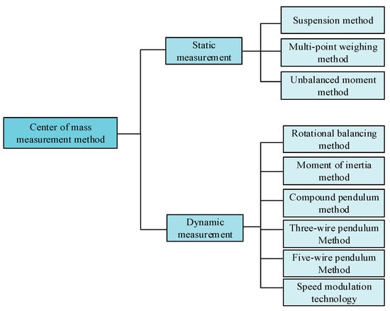
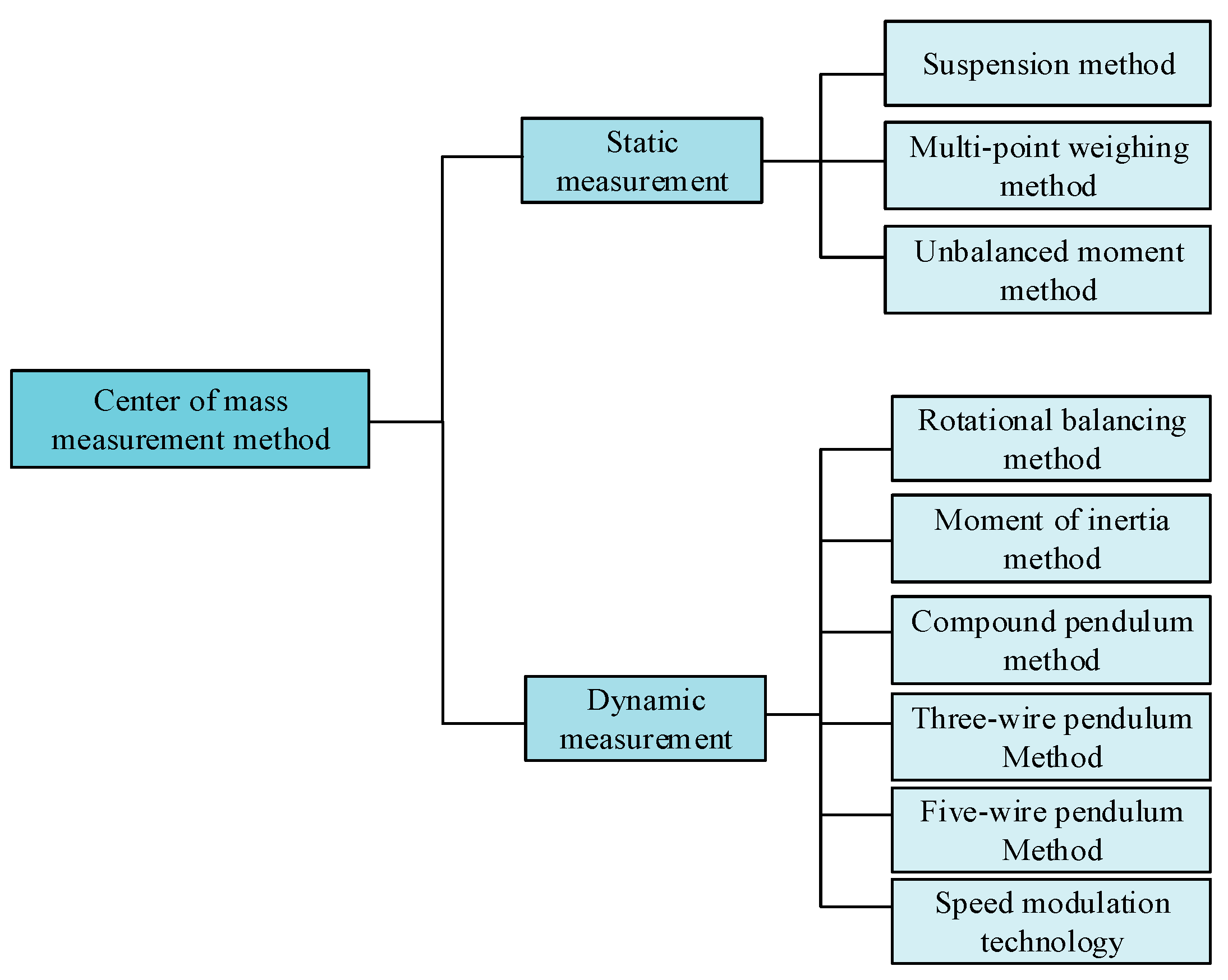
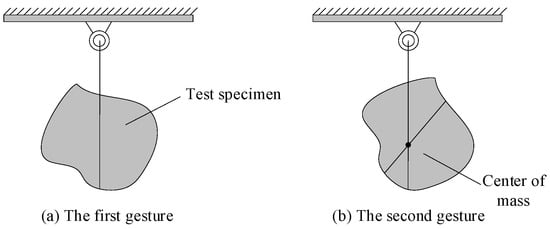
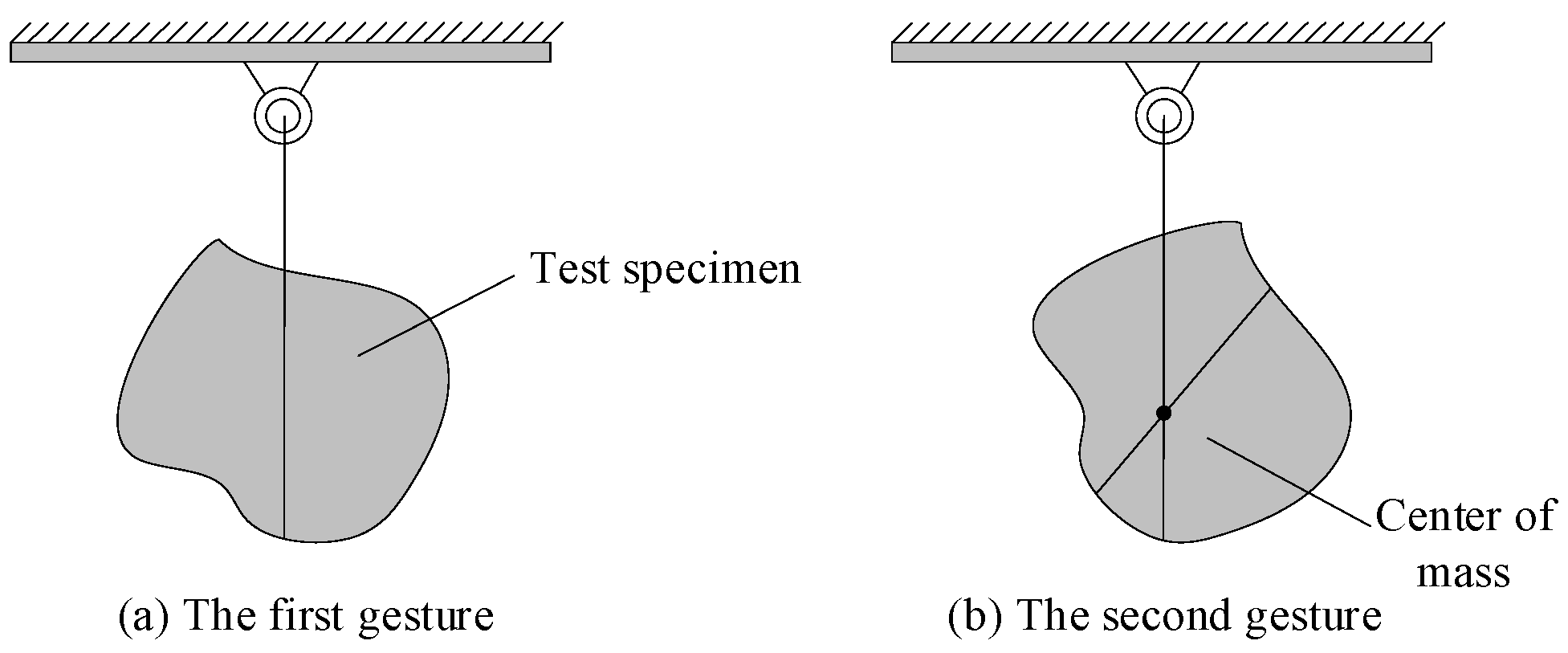
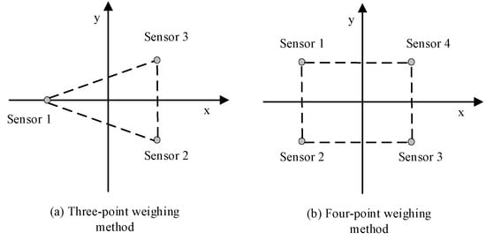
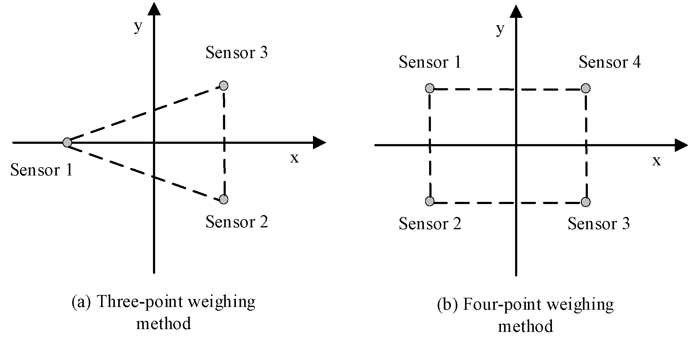
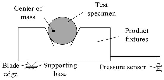
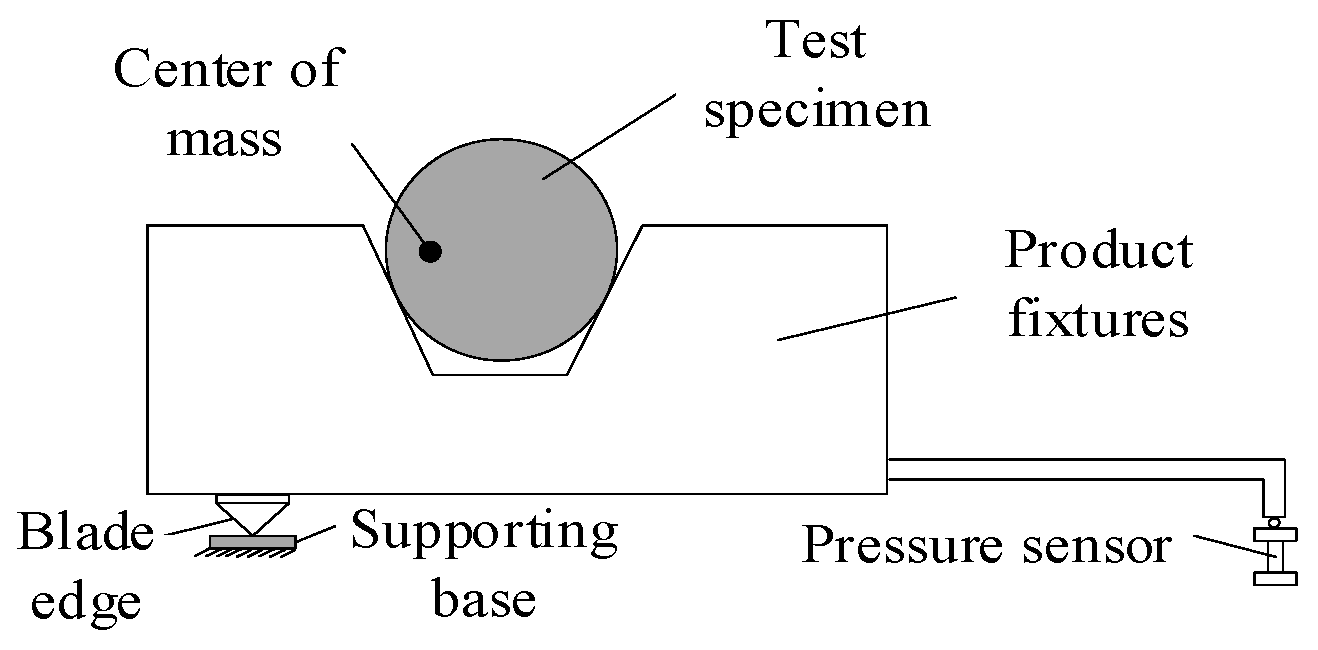
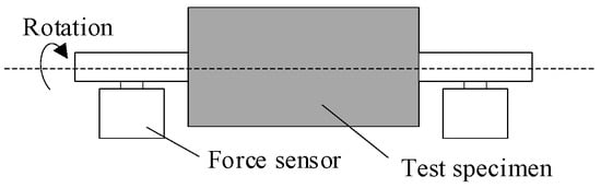
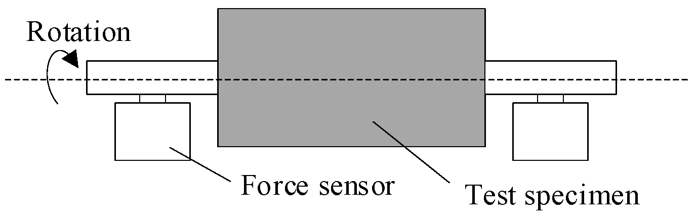
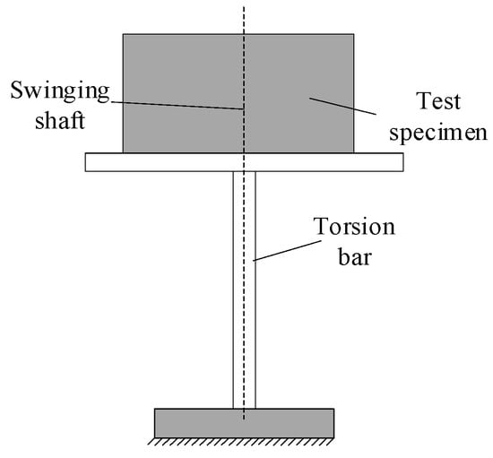
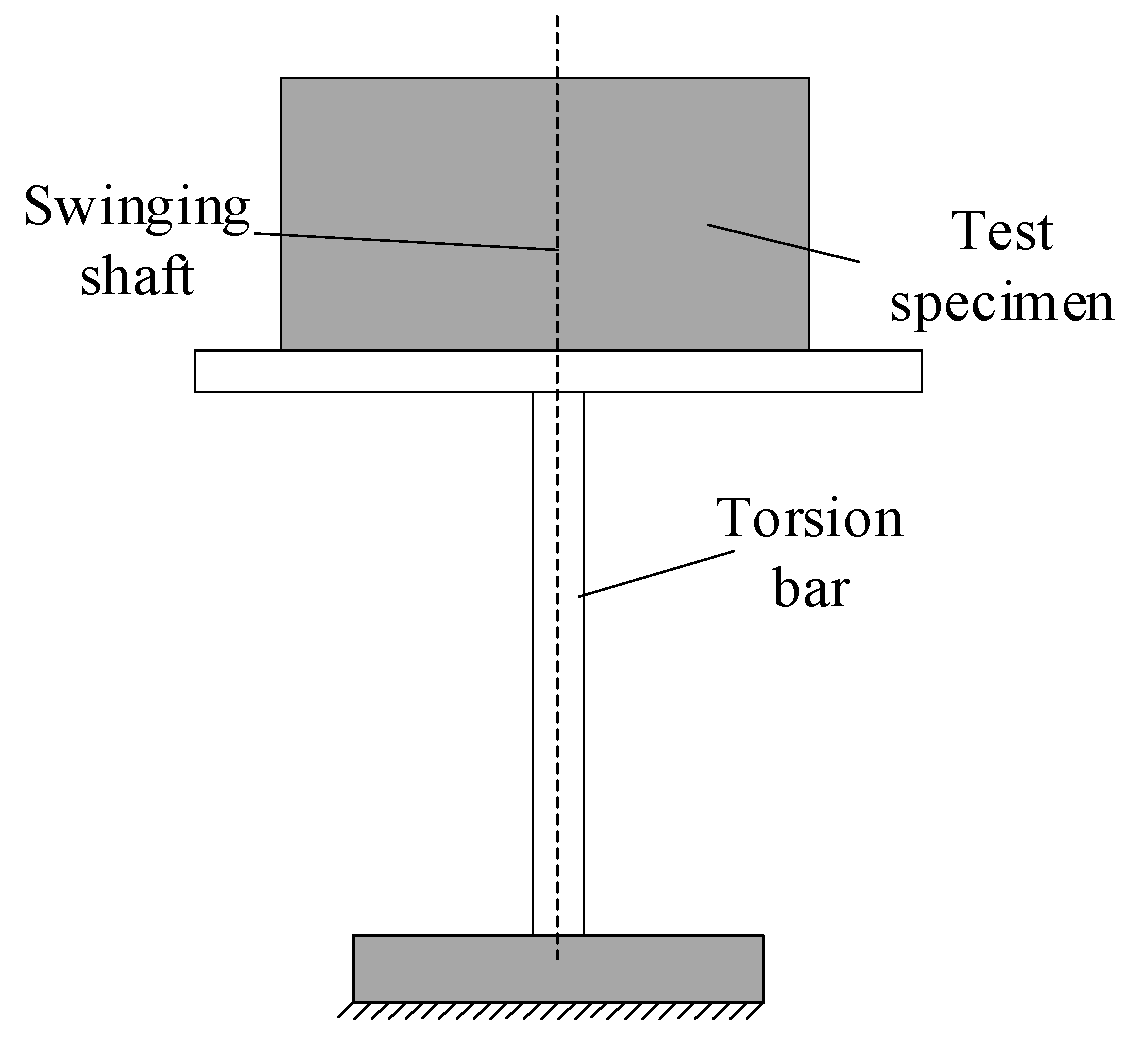
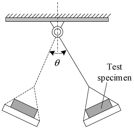
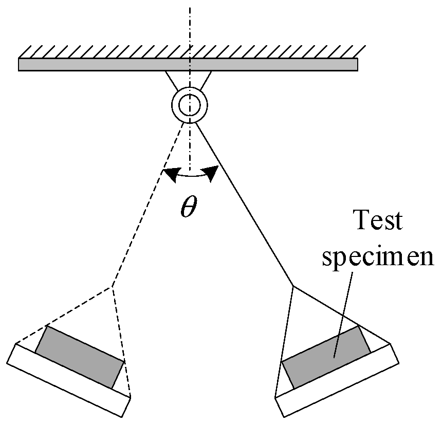
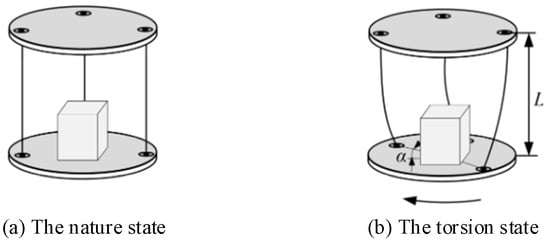
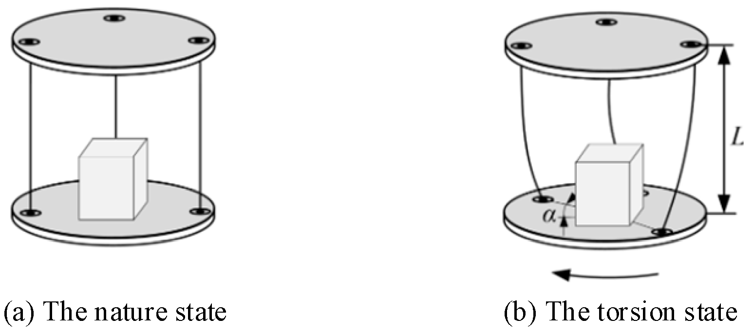
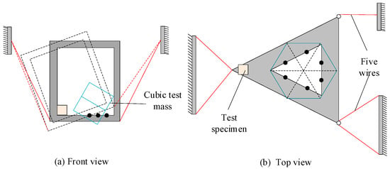

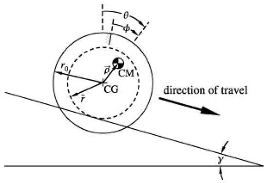
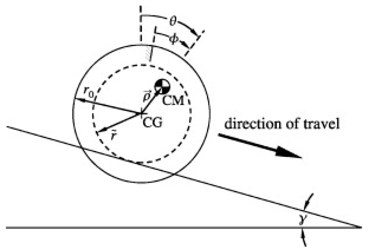
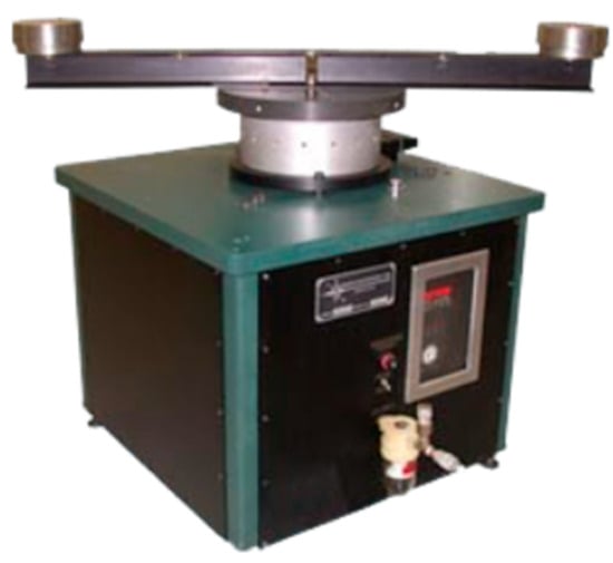
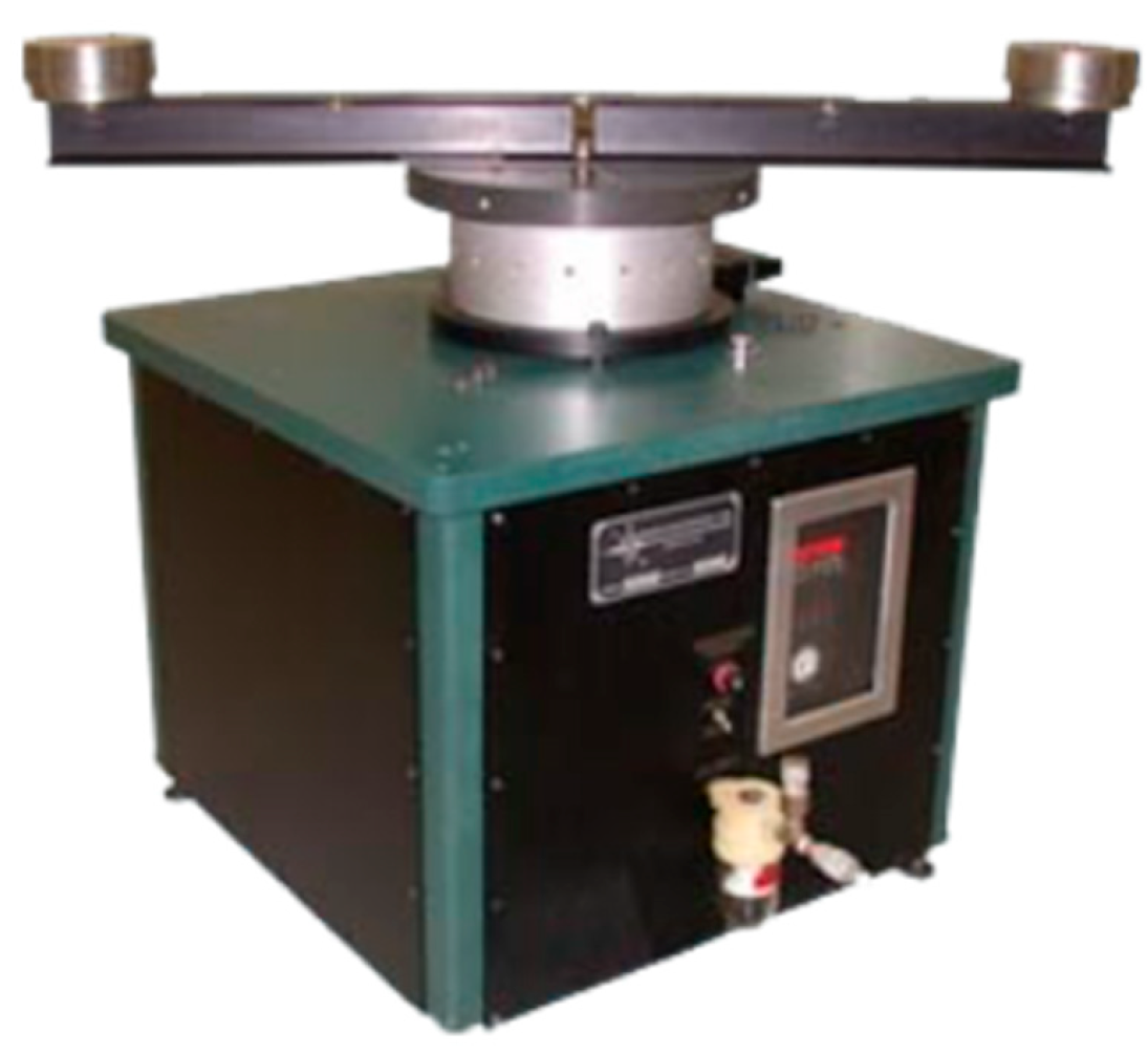
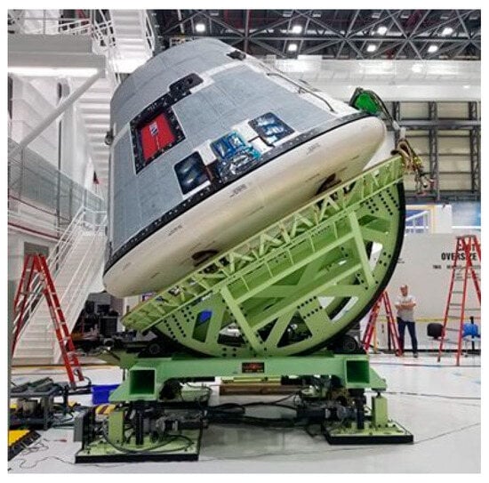
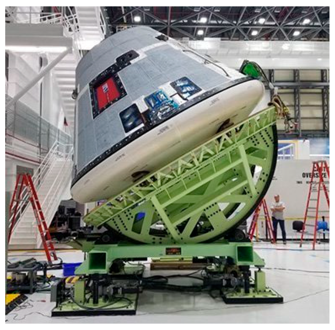
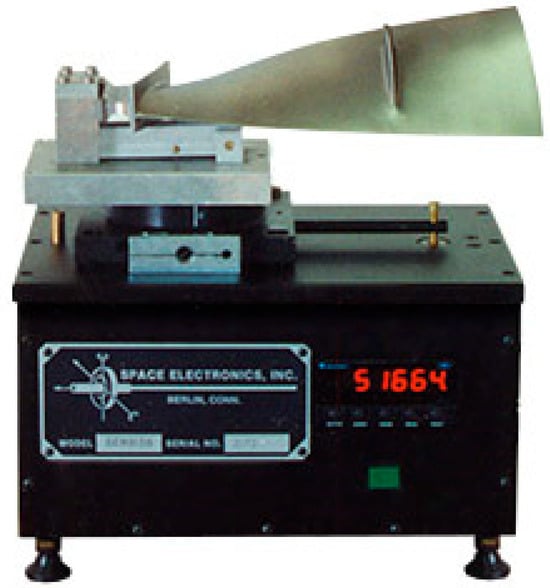
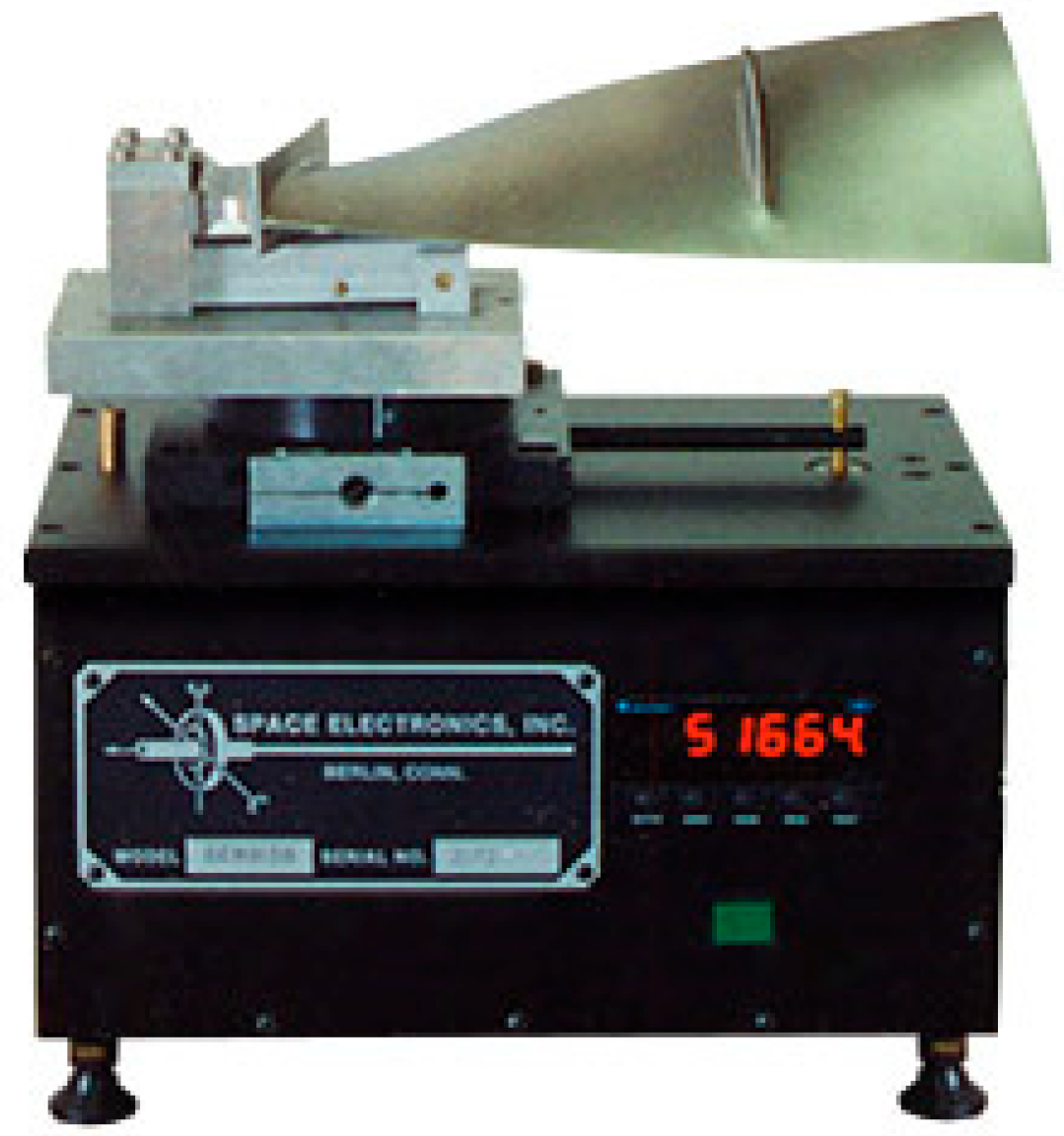
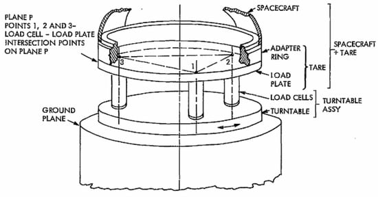
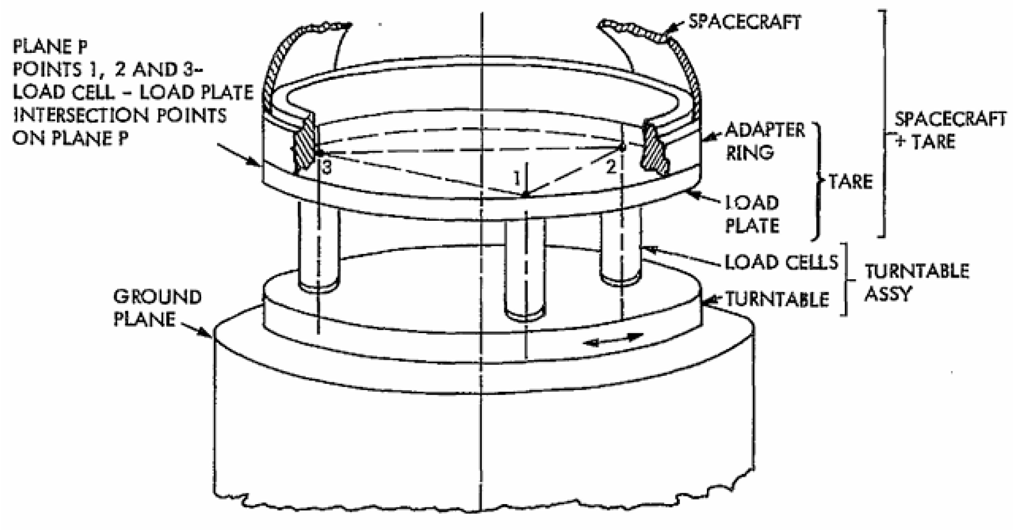
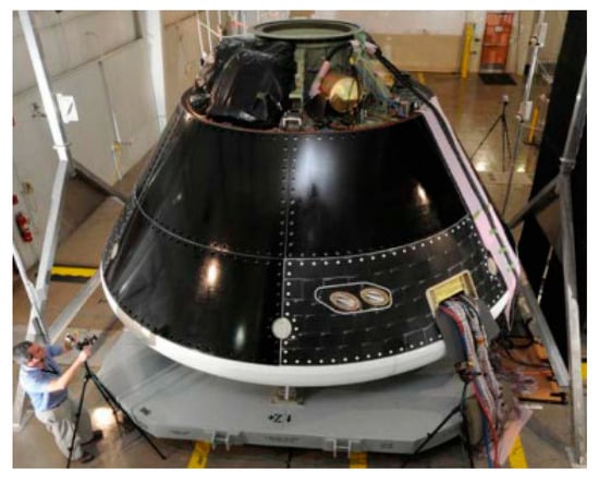
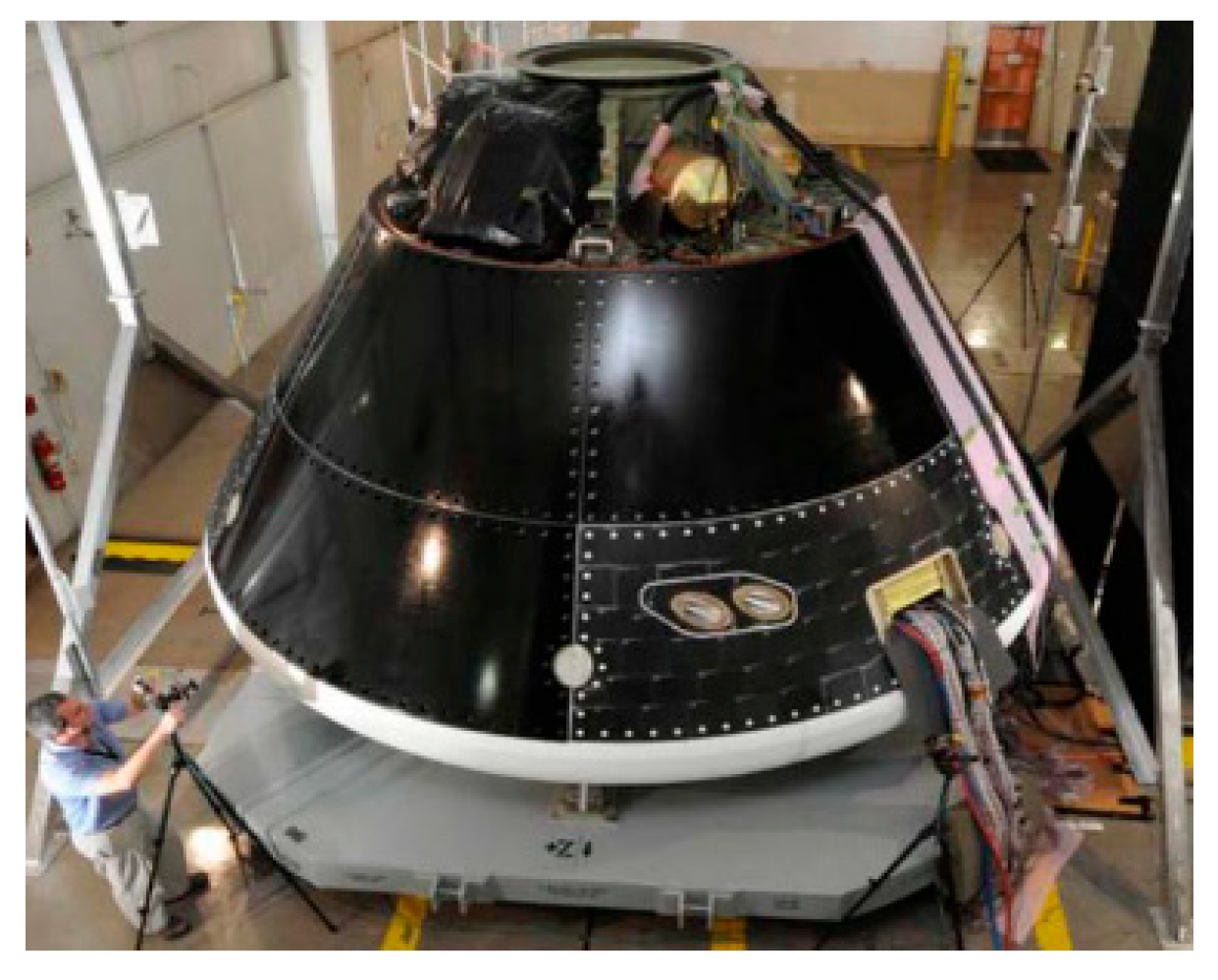
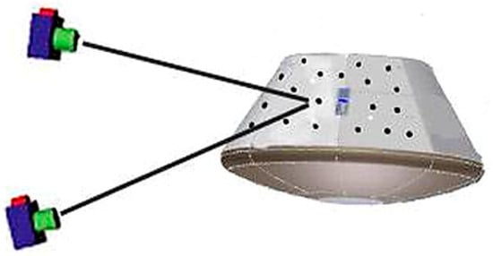
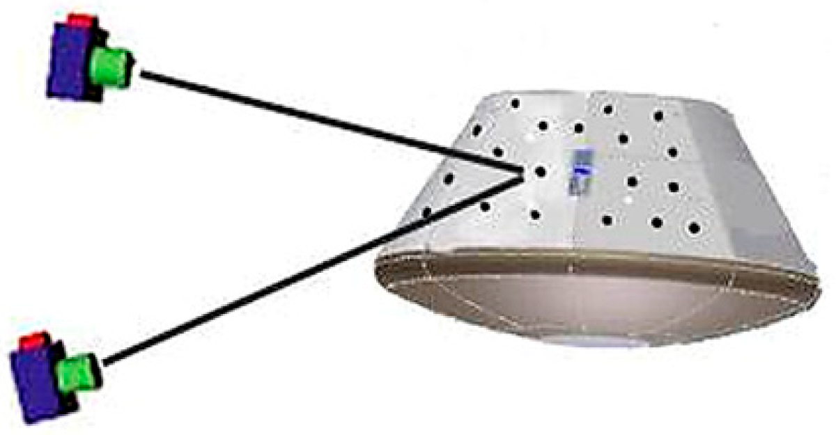
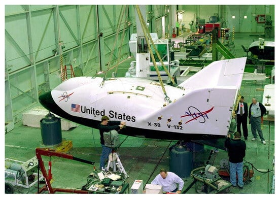
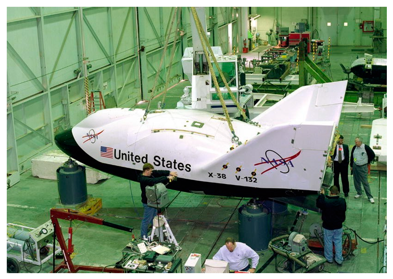
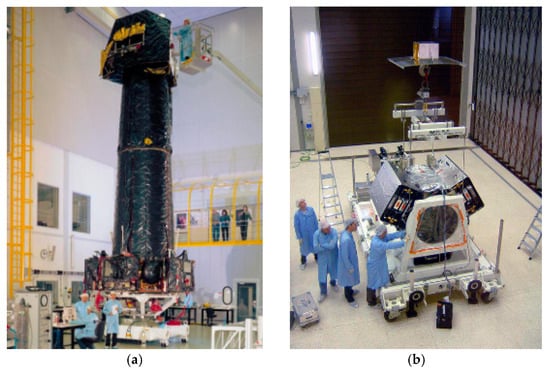
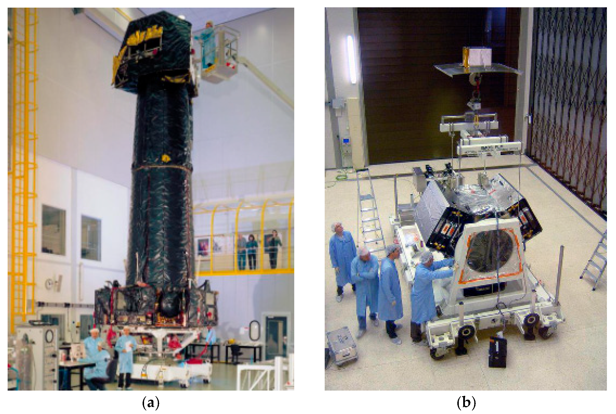
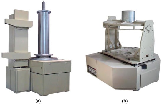
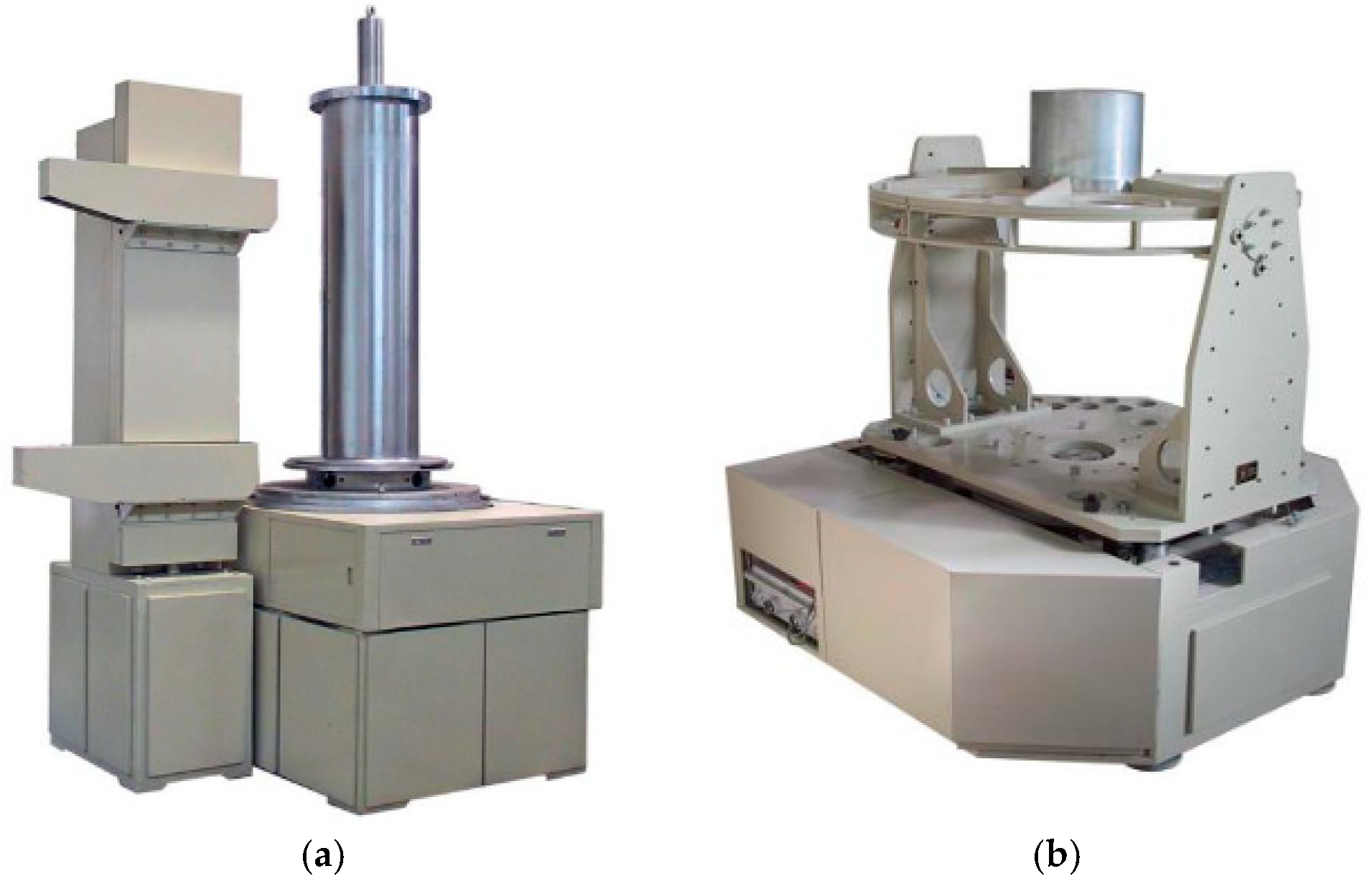
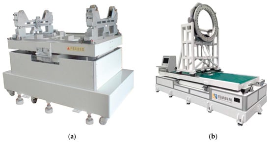
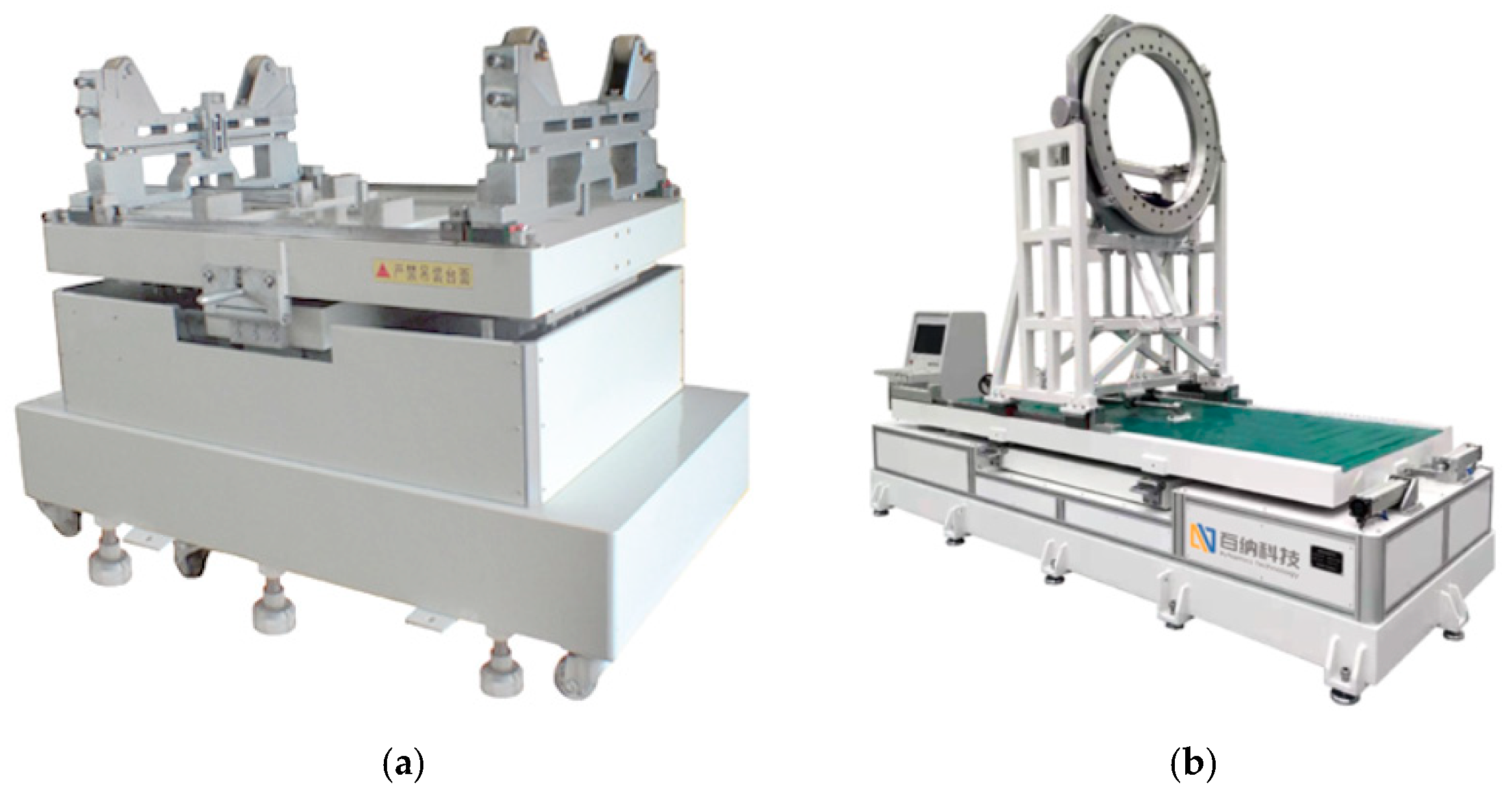
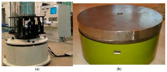
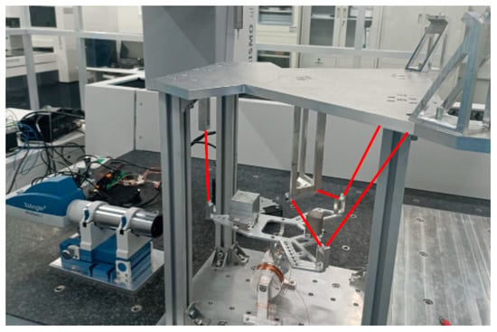
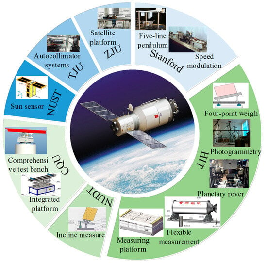

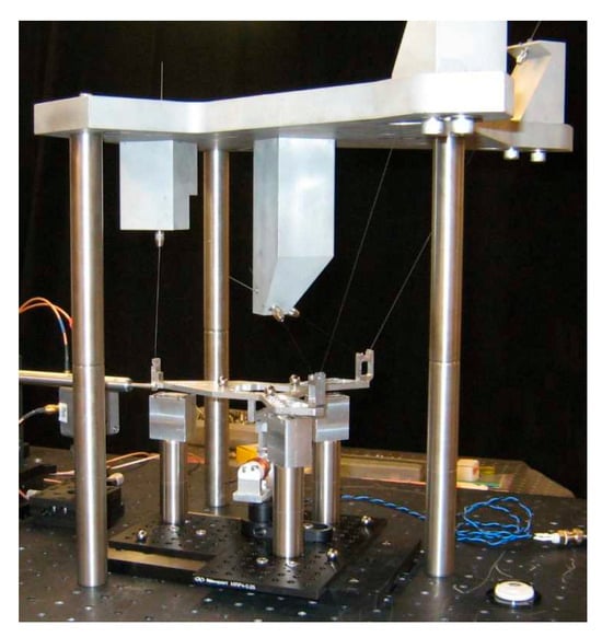
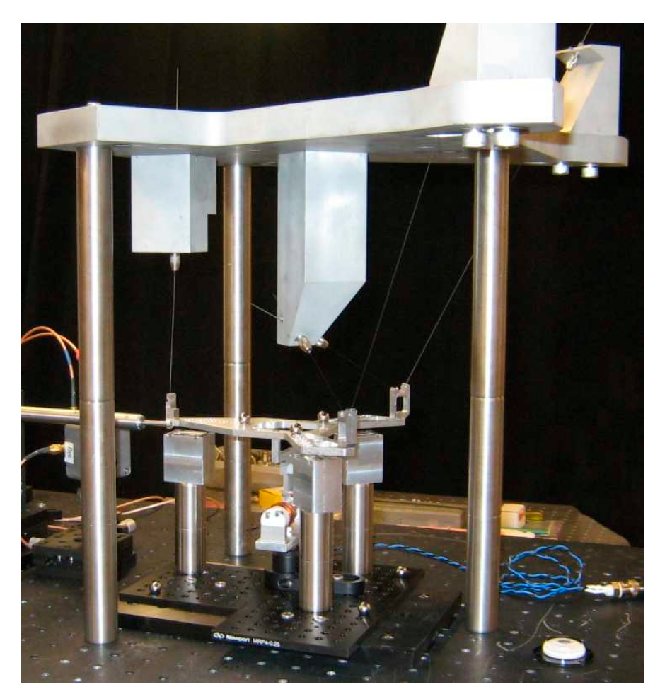
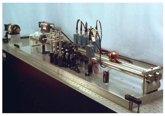
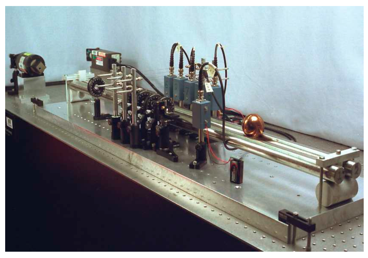
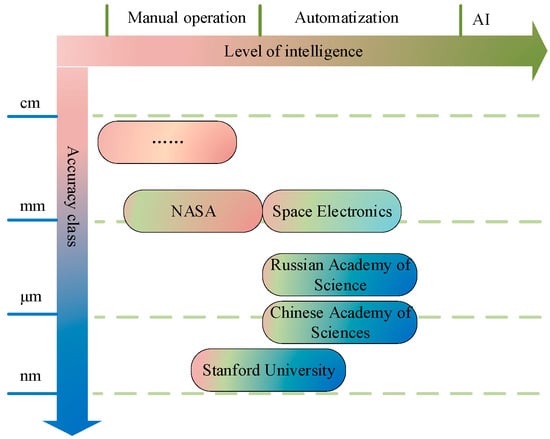
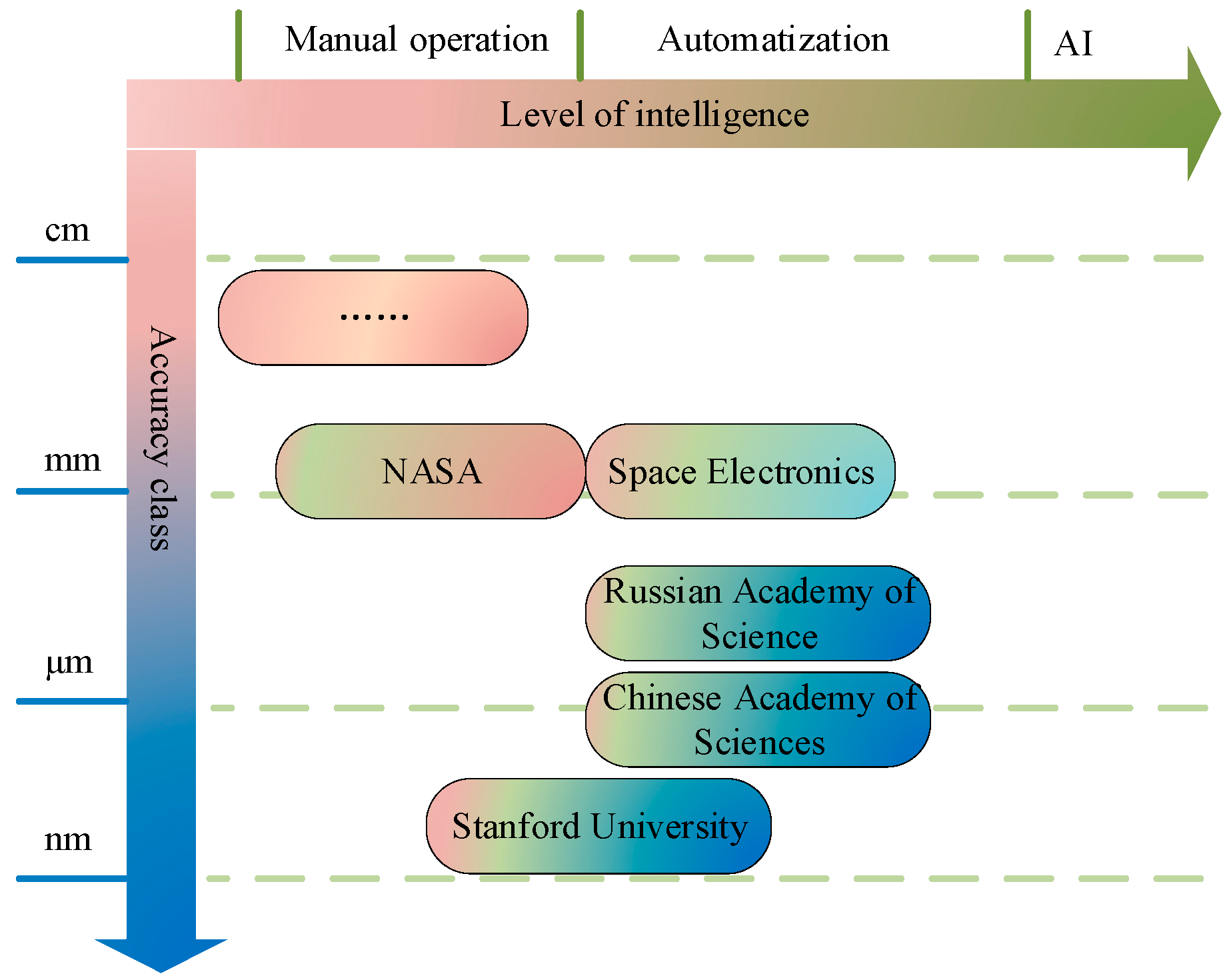

Disclaimer/Publisher’s Note: The statements, opinions and data contained in all publications are solely those of the individual author(s) and contributor(s) and not of MDPI and/or the editor(s). MDPI and/or the editor(s) disclaim responsibility for any injury to people or property resulting from any ideas, methods, instructions or products referred to in the content. |
© 2026 by the authors. Licensee MDPI, Basel, Switzerland. This article is an open access article distributed under the terms and conditions of the Creative Commons Attribution (CC BY) license.