Article

Multi-Stage Coordinated Azimuth Control for High-Precision Balloon-Borne Astronomical Platforms

1
Aerospace Information Research Institute, Chinese Academy of Sciences, Beijing 100094, China
2
University of Chinese Academy of Sciences, Beijing 100190, China
*
Author to whom correspondence should be addressed.
Aerospace 2025, 12(9), 821; https://doi.org/10.3390/aerospace12090821
Submission received: 31 July 2025 / Revised: 29 August 2025 / Accepted: 8 September 2025 / Published: 11 September 2025

Abstract

This study investigates multi-level coupled dynamic issues in near-space balloon-borne astronomical observation platforms subjected to multi-source disturbances, proposing an integrated azimuth pointing control scheme combining unified modeling with composite control strategies. A nonlinear dynamic model is established to characterize inertial coupling effects between the gondola system and secondary gimbal platform. The velocity-loop feedback mechanism utilizing fiber-optic gyroscopes achieves base disturbance decoupling, while an adaptive fuzzy PID controller enhances position-loop disturbance rejection capabilities. A gain adaptation strategy coordinates hierarchical control dynamics, complemented by anti-windup constraints safeguarding actuator operational boundaries. Simulation verifications confirm the exceptional high-precision pointing capability and robust stability under representative wind disturbances and sensor noise conditions. The system maintains a superior control performance across parameter perturbation scenarios, demonstrating consistent operational reliability. This study provides an innovative technical paradigm for precision observation missions in near space.

1. Introduction

The near space, owing to its unique strategic position, demonstrates immense potential and significant advantages in fields such as Earth remote sensing, communication relays, and cutting-edge scientific research [1]. The near-space balloon-borne astronomical observatory, positioned in near space, primarily relies on high-altitude scientific balloon platforms. This system typically comprises high-altitude balloons, tethers, gondolas, auxiliary equipment, and telescope instruments mounted within the gondola, forming a classical multi-body chain structure. Compared to traditional ground-based observatories, balloon-borne platforms can conduct astronomical observations at altitudes exceeding 30 km, unaffected by atmospheric interference. This enables superior infrared, ultraviolet, terahertz, and submillimeter-wave multiband observations, sharing advantages with space-based platforms [2,3].
Achieving precision requirements for observational tasks remains a major technical challenge in astronomy. As shown in Table 1, typical astronomical missions demand exceptionally high tracking accuracy. For near-space balloon-borne platforms, astronomical instruments mounted on the gondola require precise pointing control, as platform stability directly affects tracking accuracy and the scientific value of observational data [4].
The near-space balloon-borne platform—a “balloon–tether–gondola–pointing mechanism” kinetic system—exhibits high-order, strongly coupled, and control-constrained nonlinear dynamics. Persistent disturbances from near-space wind fields, low-frequency gondola sway, high-frequency vibrations, and intricate platform-payload coupling pose severe challenges to high-precision pointing [5].
To achieve higher-precision pointing requirements, domestic and international research teams have tended to adopt a multi-stage composite control approach: decomposing high-precision pointing challenges into successive stages, where each subsequent stage enhances control accuracy based on the preceding stage, ultimately achieving arcminute-to-sub-arcsecond precision. High-precision balloon-borne pointing systems typically adopt three-level control: Level 1 gondola attitude control, Level 2 gimbal pointing system, and Level 3 image stabilization. Level 1 gondola attitude control is managed by the balloon-borne gondola platform itself; Level 2 gimbal pointing system achieves intermediate refinement atop Level 1 control; and Level 3 image stabilization, executed by astronomical instruments, delivers fine correction based on the preceding two stages [6,7,8].
This study focuses on the field of near-space astronomical observation, aiming to develop a universal azimuth control system for balloon-borne platforms. Systematic solutions for the highly coupled dynamic interference problem in multi-loop cascade systems comprising integrated gondola control and dual-stage gimbal platforms have been proposed. First, a unified nonlinear dynamic model of the azimuth channel is established based on Lagrange equations to accurately characterize the inertial coupling effect between the gondola base and gimbal. Building upon this foundation, the velocity loop feedback is optimized through fiber-optic gyroscopes to suppress external disturbances, while the nonlinear rejection capability of the position loop is enhanced via an adaptive fuzzy PID algorithm. Furthermore, comprehensive control protection mechanisms are designed, including gain adaptation for dynamic frequency response matching to avoid control conflicts and anti-windup constraints to eliminate actuator saturation risks. Simulation results demonstrate that the system achieves arcsecond-level control accuracy (<20″) under environmental disturbances and sensor noise, while maintaining excellent robustness against parameter perturbations.
The contributions of this study are as follows:
  • Establish a unified dynamic model for the azimuth channel applicable to multi-level composite control systems of balloon-borne platforms, revealing the gondola–turret coupling mechanism.
  • Propose a dual-layer control architecture that integrates fiber-optic gyro velocity loop feedback and adaptive fuzzy PID, simultaneously enhancing disturbance rejection and robustness.
  • Design a gain adaptation mechanism to avoid multi-level control interference, combined with an anti-windup strategy to ensure actuator safety margins, guaranteeing robust azimuth pointing control under extreme operating conditions.
This paper is structured as follows: Section 2 analyzes the dynamic characteristics of the “balloon–tether–gondola–pointing mechanism” chain system and multi-level coordination mechanisms. Section 3 derives the unified azimuth channel dynamic model and quantifies inertial coupling effects. Section 4 then constructs the control system framework by designing an optimized three-loop controller and proposing protection mechanisms. Section 5 quantitatively evaluates pointing accuracy and robustness through multi-condition simulations. Section 6 summarizes key technical breakthroughs and demonstrates engineering application value.

2. System Composition and Principles

Previous research on balloon-borne astronomical observation platforms by domestic and international teams has predominantly employed multi-level composite control strategies. These strategies rationally allocate precision improvements across the primary integrated gondola azimuth control system, the secondary tier-2 gondola gimbal pointing system, and the tertiary image stabilization control, ultimately achieving high-precision observational accuracy with superior cost-effectiveness. As indicated in Table 2, balloon-borne pointing platforms provide a pointing accuracy of around 20 arcseconds while maintaining high cost-effectiveness.
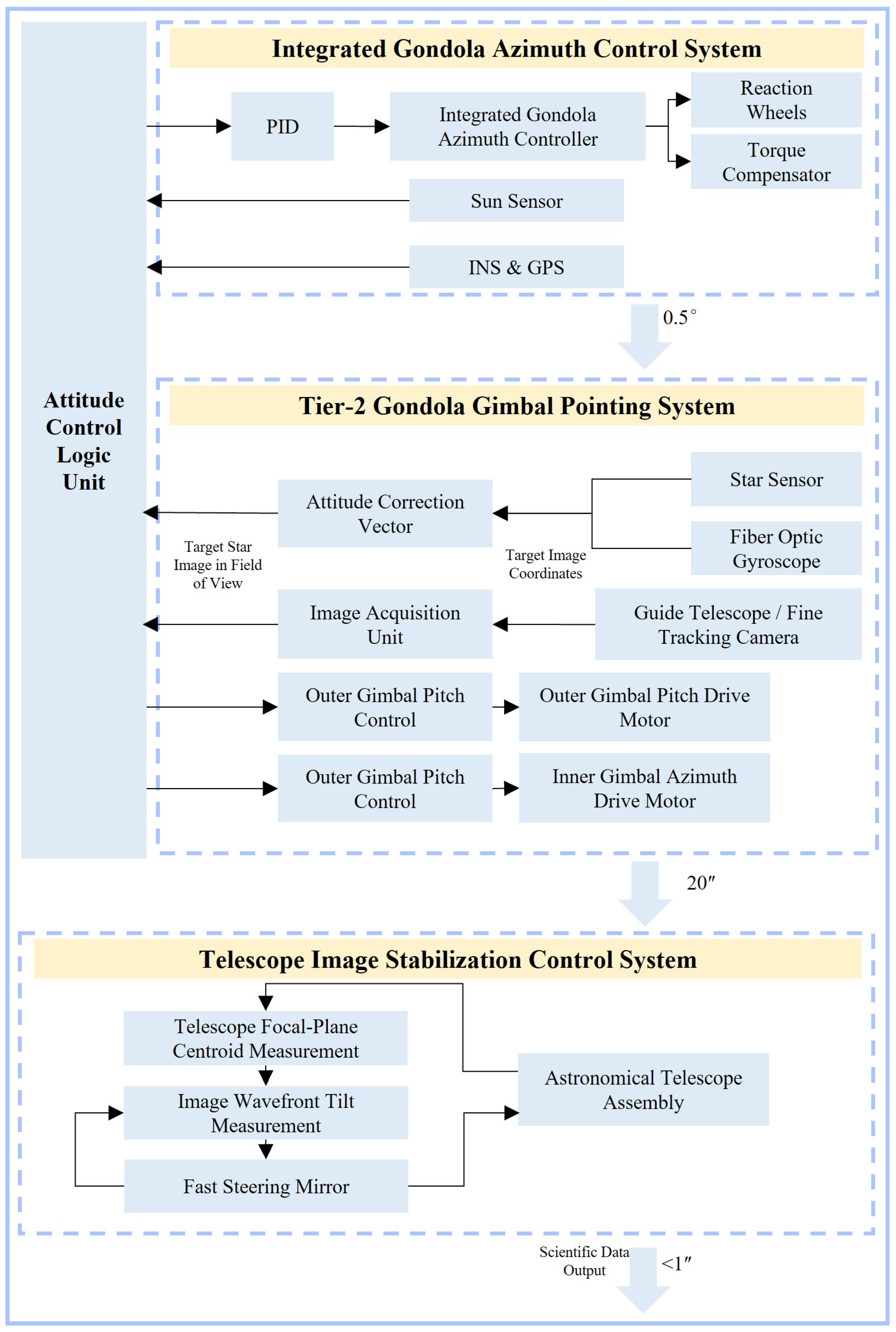
Synthesizing high-precision and cost-effective requirements, this study designs a self-developed universal near-space balloon-borne astronomical observation platform, with its main structure illustrated in Figure 1. The platform employs a multi-level composite control strategy, structurally divided into an integrated gondola azimuth control system and a tier-2 gondola gimbal control system. The gondola azimuth control system, consistent with conventional balloon-borne gondola attitude control architectures, utilizes torque compensator and reaction wheels for cooperative azimuth–axis regulation. The tier-2 gondola gimbal control system achieves precise pointing through coordinated adjustments of the gimbal and payload within the gondola.
The control architecture of the near-space balloon-borne astronomical observation platform, as illustrated in Figure 2, employs a hierarchical strategy. The integrated gondola azimuth control system achieves 360° omnidirectional control, primarily suppressing low-frequency, large-scale azimuth deviations or disturbances of the aerostat platform, albeit with a narrow bandwidth; its control accuracy requirement is 0.5°. Building upon the gondola system, the tier-2 gondola gimbal pointing system further suppresses higher-frequency oscillations, stabilizing pointing accuracy at the 20-arcsecond level. The synergistic operation of both control tiers provides a stable observational foundation for astronomical payloads (e.g., telescope pointing columns) leveraging the platform’s 20-arcsecond precise pointing, and the astronomical payload team implements fine image stabilization control using mature fast steering mirror (FSM) technology, ultimately enhancing the telescope pointing accuracy to 1 arcsecond or better—meeting stringent astronomical observation requirements [9,10].
The integrated gondola azimuth control system employs attitude control technologies prevalent in balloon-borne gondolas: reaction wheels enable momentum exchange to generate azimuth control torque, driving the gondola to rotate toward the set orientation; torque compensators isolate balloon rotation and provide torque unloading to prevent wheel saturation [11].
As illustrated in Figure 3, the tier-2 gondola gimbal pointing system typically employs two control configurations:
  • The “outer azimuth + inner elevation” structure is employed in Japan’s FUJIN planetary telescope [12], and the coronagraph project of the Yunnan Observatories, Chinese Academy of Sciences [13]. This configuration enables independent development and testing of the turntable. However, to ensure sufficient structural stiffness, the mass inertia moment of the azimuth frame is intentionally increased, leading to potential dynamic coupling between the turntable’s azimuth–axis control and the integrated azimuth control system, which may induce control coordination conflicts.
  • The “outer pitch and inner azimuth” structure is utilized in the Solar Telescope BST of Beijing Astronomical Observatory, Chinese Academy of Sciences [14] and NASA’s WASP high-precision pointing gondola [15,16]. This design features reduced mass and inertia in both elevation and azimuth channels of the secondary turntable, minimizing interference with the integrated gondola azimuth control system and facilitating higher pointing accuracy. Nevertheless, a significant drawback is that standalone debugging of the secondary turntable is infeasible, necessitating dedicated interface adapters for calibration and testing.
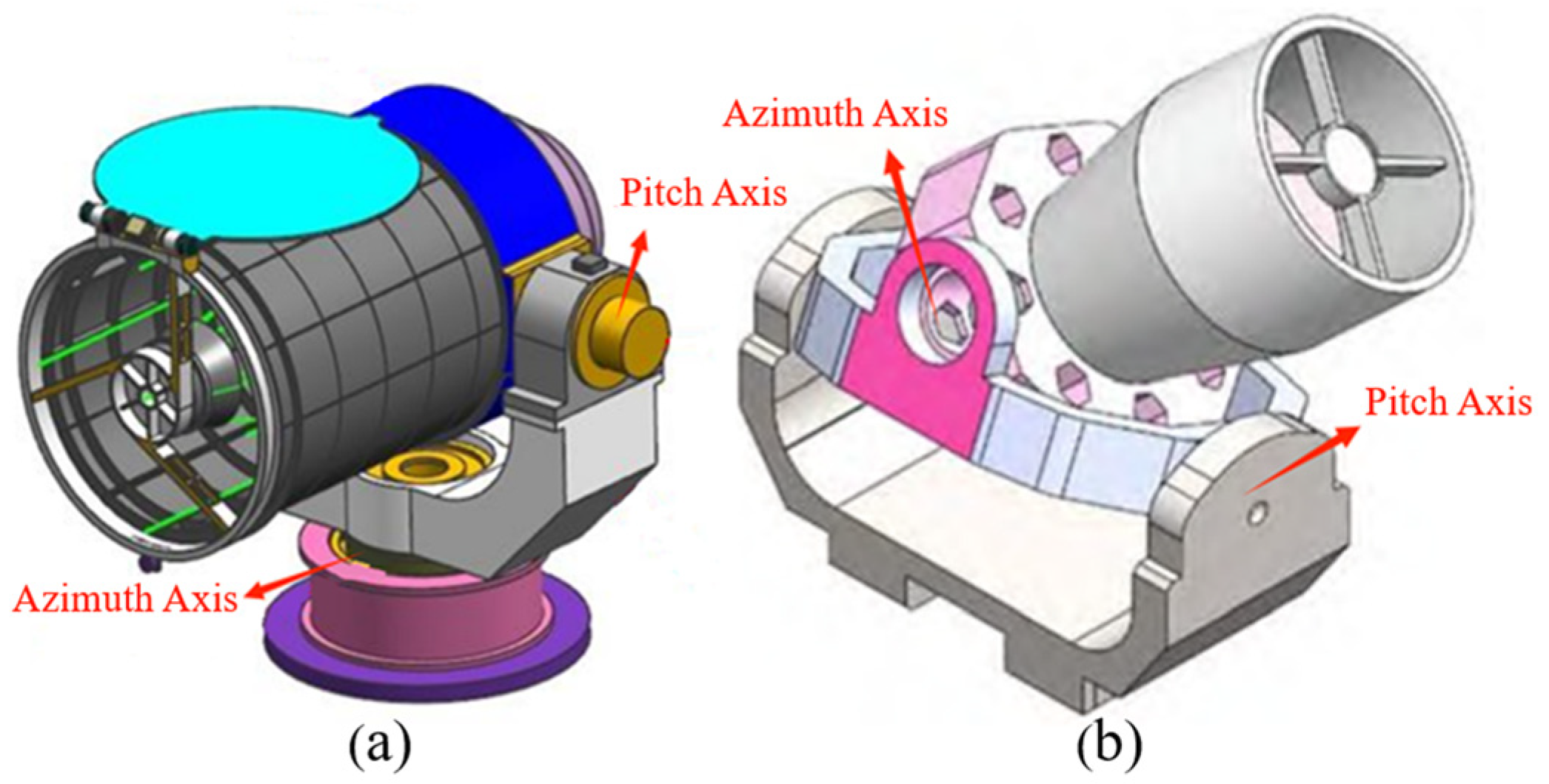
Figure 3. Schemes of two control structures: (a) outer azimuth and inner pitch configuration; (b) outer pitch and inner azimuth configuration.
Aerospace 12 00821 g003
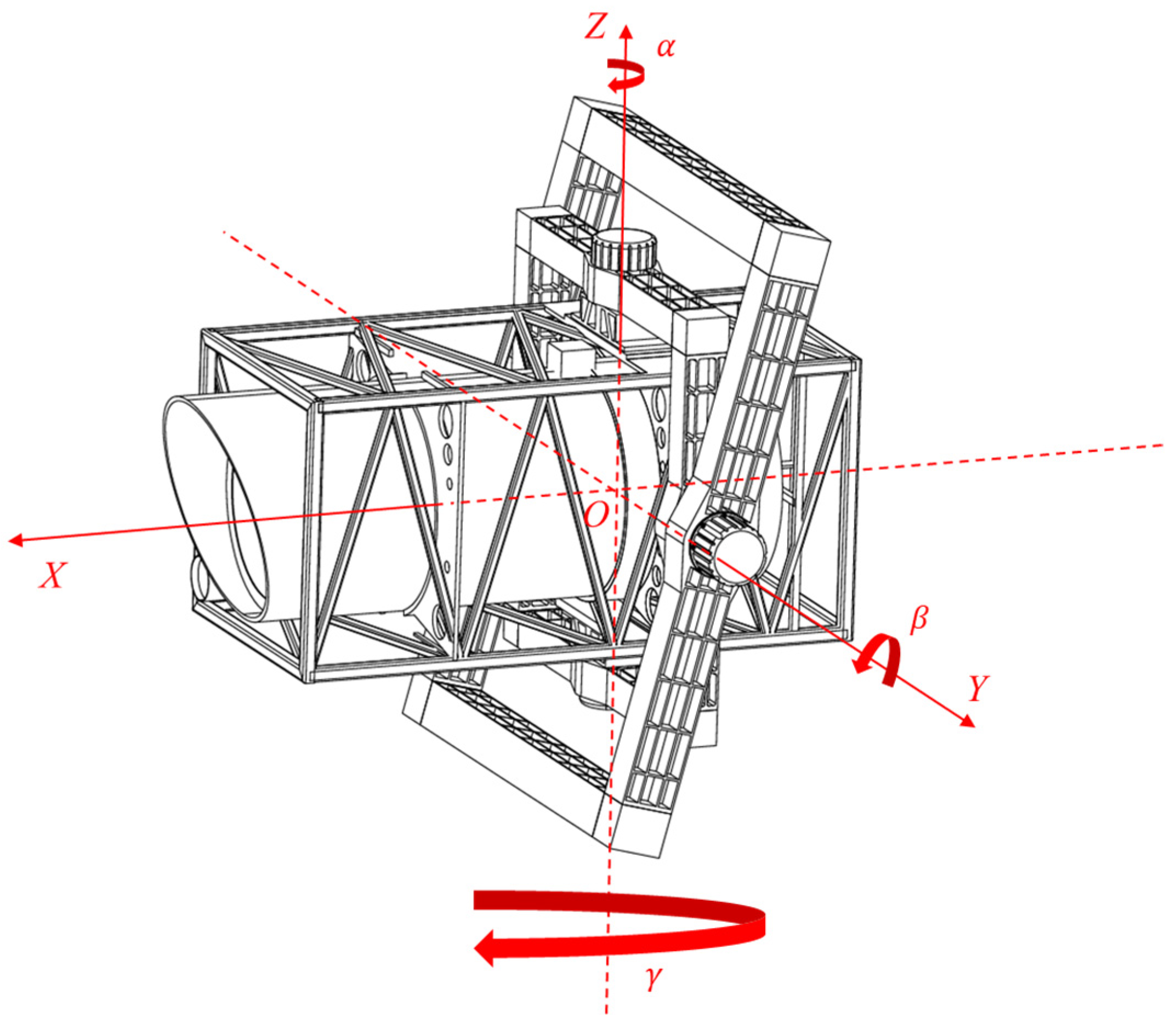
To enhance pointing precision, the near-space balloon-borne astronomical observation platform in this study adopts an outer pitch/inner azimuth configuration, with the gimbal structure shown in Figure 4. The outer frame is rigidly affixed to the gondola, while the telescope (pointing column) is housed within the inner frame. The azimuth motor, mounted on the inner frame, drives the telescope’s azimuth–axis motion; the pitch drive motor, installed on the outer frame, propels the integrated assembly of the inner frame and telescope to achieve elevation–axis motion. Given the pronounced dynamic coupling effects between the gondola and the gimbal turntable, a comprehensive dynamic model must be established for holistic cooperative control design. For such complex control systems, prior research predominantly adopted decoupling assumptions for the azimuth and elevation channels, conducting independent analysis and design for each control channel [17,18].
To mitigate disturbances from high-altitude balloon turbulence on observational instruments, near-space balloon-borne astronomical platforms typically employ a payload suspension system with 150–250 m tethers. This configuration effectively isolates the gondola from balloon-induced disturbances on the pitch axis. Given the low wind disturbance intensity in near-space and its negligible impact on pitch channel control, the dynamic coupling effects between externally induced pitch motion and the pointing system’s pitch channel are insignificant. Consequently, pitch control can be simplified as an independent task executed solely by the secondary turntable. However, azimuth control requires synergistic operation between the integrated azimuth stabilization system and the secondary turntable’s azimuth servo system, forming a dual-drive architecture. Within this framework, the integrated system compensates for balloon rotation via reaction wheels or a torque compensator, while the gimbal system performs precision azimuth tracking within the inner frame. Their distinct dynamic response characteristics may induce velocity loop conflicts, torque interference, or even oscillation divergence if coordination is improperly designed, severely constraining pointing accuracy and system stability. Thus, research on multi-level coupling control mechanisms for the azimuth channel is critical for enhancing the engineering reliability of near-space astronomical observation platforms.

3. Dynamics Modeling

As a rigid-body system subject to holonomic constraints, the near-space balloon-borne astronomical platform requires collaborative control between the integrated azimuth stabilization system and the secondary turntable servo system for its azimuth channel. Establishing a unified dynamics framework under generalized coordinates simplifies system analysis and computation. Furthermore, given the multi-body coupling characteristics of the balloon-borne platform, the Lagrange formulation necessitates only active force terms such as gravitational potential energy and motor drive torques, thereby significantly streamlining the modeling process in non-conservative force-dominated environments. Based on these considerations, Lagrange’s equations are employed to derive the system dynamics model.

3.1. Parameters and Coordinate System Definitions

The primary structure of the secondary gimbal system comprises an outer gimbal, an inner gimbal, and a pointing column. The outer gimbal is rigidly affixed to the gondola, with its motion exclusively controlled by the integrated azimuth stabilization system. Relative to the gondola, the entire secondary gimbal system possesses two degrees of freedom: (1) the inner gimbal and pointing column are driven by a pitch motor to execute pitch motion relative to the outer gimbal; (2) the pointing column is driven by an azimuth motor to perform azimuth rotation relative to the inner gimbal.
To simplify the analysis, the following engineering-feasible assumptions are adopted:
  • The outer gimbal, inner gimbal, and pointing column are considered ideal rigid bodies, with elastic deformation and structural resonance effects neglected during motion;
  • The mass and rotational inertia of auxiliary components (e.g., sensors, cables) beyond the primary structure are negligible, ensuring that the system’s center of mass and inertia tensor are solely determined by the primary structure;
  • The pointing axis, inner gimbal axis, and outer gimbal axis are assumed to intersect at a common spatial point O, defined as the theoretical center of rotation for the gimbal system, with the total center of mass of the secondary gimbal system coinciding with this point;
  • The outer gimbal is rigidly connected to the gondola, whereby translational/oscillatory disturbances of the gondola are transmitted through the base of the outer gimbal.
The simplified dynamic model of the tier-2 gondola gimbal pointing system is illustrated in Figure 5. Let the pitch rotation angle of the inner gimbal be denoted as β , and the azimuth rotation angle of the pointing column as α . The outer gimbal serves as a fixed mounting base rigidly connected to the gondola. At the initial moment, the pointing axis is aligned with the horizontal direction, with β = 0 and α = 0 . Four coordinate systems are defined: inertial frame oxyz , mounting-base frame o x o y o z o , inner-gimbal frame o x m y m z m , and pointing-axis frame o x i y i z i . The xᵢ-axis always coincides with the pointing axis, while the zm-axis remains aligned with the inner gimbal axis. The origin O of all frames is located at the system center of mass. At the initial moment, the mounting-base frame o x o y o z o , inner-gimbal frame o x m y m z m , and pointing-axis frame o x i y i z i are coincident: the xᵢ-axis aligns with the xm-axis and xo-axis; the yᵢ-axis aligns with the ym-axis and yo-axis; and the zᵢ-axis aligns with the zm-axis and zo-axis. The azimuth orientation angle of the gondola at the initial moment is γ . The transformational relationships between these coordinate systems are as follows:
x y z = cos γ sin γ 0 sin γ cos γ 0 0 0 1 cos β 0 sin β 0 1 0 sin β 0 cos β cos α sin α 0 sin α cos α 0 0 0 1 x i y i z i ,

3.2. Lagrangian Modeling

Generalized coordinates are defined as α , β , and γ , with the oxy-plane designated as the zero-potential surface. It is assumed that the generalized forces acting on the system comprise a gravitational force G and gimbal control torque M, among which G is a conservative force.
M = T e T f = M α + M β ,
where T e is defined as the motor drive torque, T f as the gimbal friction torque; M α as the azimuth control torque exerted by the pointing column on the generalized coordinate α , and M β as the pitch control torque applied by the inner gimbal to the generalized coordinate β .
The moments of inertia of respective kinematic segments are defined as follows:
J o = d i a g ( J o x , J o y , J o z ) ,
J m = d i a g ( J m x , J m y , J m z ) ,
J i = d i a g ( J i x , J i y , J i z ) ,
where J o denotes the inertia tensor of the mounting-base frame o x o y o z o ; J m represents the inertia tensor of the inner-gimbal frame o x m y m z m ; and J i signifies the inertia tensor of the pointing-axis frame o x i y i z i .
Furthermore, for components associated with J o , J m , and J i in the gimbal system, their principal axes of inertia are parallel to the respective axes of frame o x o y o z o , frame o x m y m z m , and frame o x i y i z i .
Let ω i and ω m be the angular velocity vectors of the pointing column and inner gimbal relative to the mounting base, respectively, and ω o be the angular velocity vector of the mounting base. Thus,
ω i = α ˙ + β ˙ + γ ˙ ,
ω m = β ˙ + γ ˙ ,
ω o = γ ˙ ,
where α ˙ is defined as the azimuth angular velocity of the pointing column, β ˙ as the pitch angular velocity of the inner gimbal, and γ ˙ as the azimuth angular velocity of the gondola.
To facilitate subsequent calculations, the angular velocity vectors should be expressed in a unified coordinate system. Specifically, ω i is expressed in frame o x i y i z i , ω m in frame o x m y m z m , and ω o in frame o x o y o z o , which are, respectively, denoted as ω i i , ω m m , and ω o o , as follows:
ω i i = β ˙ sin α γ ˙ cos α sin β β ˙ cos α + γ ˙ sin α sin β α ˙ + γ ˙ cos β ,
ω m m = γ ˙ sin β β ˙ γ ˙ cos β ,
ω o o = 0 0 γ ˙ ,
The total kinetic energy T of the system is calculated as
T = T i + T m + T o = 1 2 ω i i T J i ω i i + 1 2 ω m m T J m ω m m + 1 2 J o z γ ˙ 2 ,
When only the azimuth channel is considered, with the gimbal pitch angle β assumed constant and both the gondola pitch and roll angles equal to zero, the gravitational potential energy remains constant. This yields:
ω i i = γ ˙ cos α sin β γ ˙ sin α sin β α ˙ + γ ˙ cos β ,
ω m m = γ ˙ sin β 0 γ ˙ cos β ,
ω o o = 0 0 γ ˙ ,
The Lagrange equation of the system is established:
d d t T α ˙ T α = M α ,
d d t T γ ˙ T γ = 0 ,
Substitution yields the dynamics equation:
J i z α ¨ + γ ¨ cos β 1 2 γ ˙ 2 sin 2 β sin 2 α J i y J i x = M α ,
sin 2 β J i x cos 2 α + J i y sin 2 α + J m x + cos 2 β J i z + J m z + J o z γ ¨ + J i z α ¨ cos β + γ ˙ α ˙ sin 2 β sin 2 α J i y J i x = 0 ,
For large azimuth deviations, full-gondola azimuth control is adopted, and the dynamics equation becomes
sin 2 β J i x cos 2 α + J i y sin 2 α + J m x + cos 2 β J i z + J m z + J o z γ ¨ + J i z α ¨ cos β + γ ˙ α ˙ sin 2 β sin 2 α J i y J i x = M ω ,
where M ω denotes the control torque generated by the reaction wheel and reaction torque actuator.
To construct the state-space equations, define
ω α = α ˙ ,
ω γ = γ ˙ ,
where ω α represents the azimuth angular velocity of the pointing column, and ω γ denotes the azimuth angular velocity of the gondola.
The derived dynamics equation is expressed as
A ω ˙ α ω ˙ γ + B = M α M w ,
where
A = J i z J i z cos β J i z cos β sin 2 β J i x cos 2 α + J i y sin 2 α + J m x + cos 2 β J i z + J m z + J o z ,
B = sin 2 β sin 2 α J i y J i x ω γ 1 2 ω γ ω α ,
where ω ˙ α signifies the azimuth angular acceleration of the pointing column, and ω ˙ γ indicates the azimuth angular acceleration of the gondola.
Given that the inner gimbal pitch angle β is constant and the pointing column azimuth angle α is small during secondary fine-tuning control, the model is linearized under condition 5 by neglecting higher-order nonlinear terms. The linearized equation is obtained:
A ω ˙ α ω ˙ γ = M α M w ,
Let
A 1 = J 11 ˜ 1 J 12 ˜ 1 J 21 ˜ 1 J 22 ˜ 1 ,
where
J 11 ˜ 1 = sin 2 β J i x + J m x + cos 2 β J i z + J m z + J o z J i z ( sin 2 β J i x + J m x + cos 2 β J m z + J o z ) J 12 ˜ 1 = cos β sin 2 β J i x + J m x + cos 2 β J m z + J o z J 21 ˜ 1 = cos β sin 2 β J i x + J m x + cos 2 β J m z + J o z J 22 ˜ 1 = 1 sin 2 β J i x + J m x + cos 2 β J m z + J o z ,
Then,
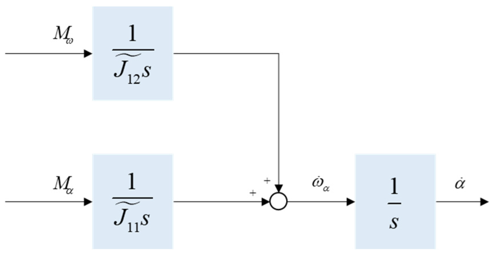
ω ˙ α ω ˙ γ = J 11 ˜ 1 J 21 ˜ 1 M α + J 12 ˜ 1 J 22 ˜ 1 M ω ,
ω ˙ α = J 11 ˜ 1 M α + J 12 ˜ 1 M ω ω ˙ γ = J 21 ˜ 1 M α + J 22 ˜ 1 M ω ,
Thus, the azimuth-channel dynamics model of the pointing system is fully established.

4. Control Algorithm Design and Analysis

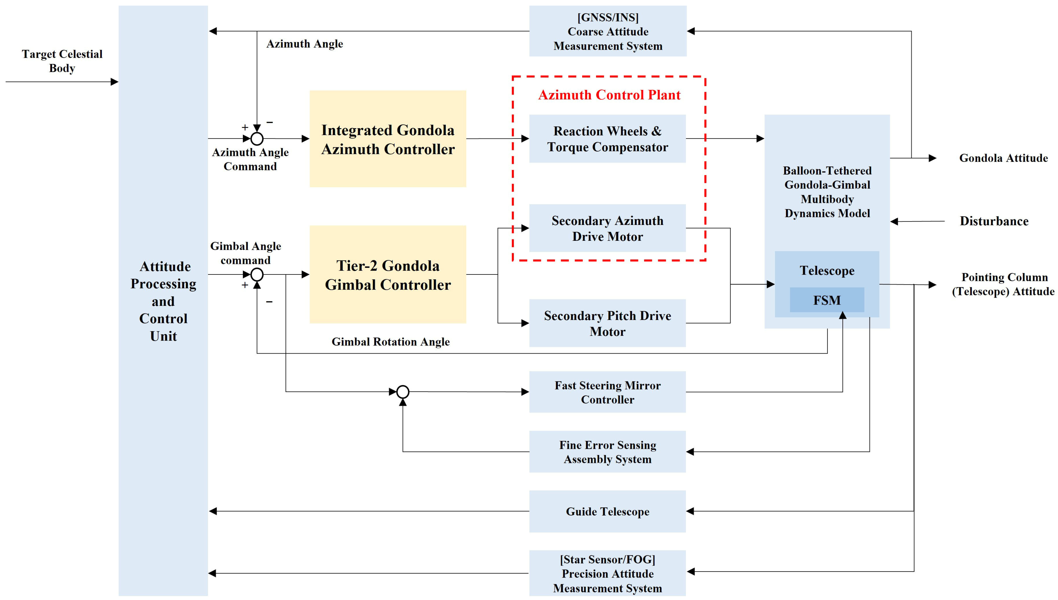
The balloon-borne astronomical observatory pointing system consists of the integrated gondola azimuth control system and the tier-2 gondola gimbal pointing system (Figure 6). The multi-loop cascaded compound control formed by these two subsystems essentially constitutes a compound pointing control for the attitude-controlled gondola and the internal secondary turntable. This system exhibits coupling and mutual interference between control channels at different levels; whereas the full-gondola azimuth control system provides coarse control in the azimuth channel, the tier-2 gondola gimbal controller delivers fine control in the dual-channel (azimuth and pitch).
The integrated gondola azimuth control system is fundamentally an enhancement of the conventional balloon-borne gondola attitude control system. Its operational principles have been thoroughly investigated in References [19,20,21]. This system provides the balloon-borne observatory with a fundamental coarse pointing accuracy of <1°.
The azimuth and pitch axes of the tier-2 gondola gimbal pointing system form relatively independent motion control systems (Figure 7), primarily comprising brushless torque motors, current sensors, and encoders with associated signal conditioning circuitry. This secondary system functions as a high-precision servo motion system, employing a three-loop architecture in an inner-to-outer sequence: Current Loop (ACR) → Velocity Loop (ASR) → Position Loop (APR).
To effectively coordinate the multi-level collaborative framework between the integrated gondola azimuth control system and the tier-2 gondola gimbal pointing system, and to resolve the resulting channel dynamics coupling and mutual interference issues, this study systematically designs a core controller architecture and incorporates critical protection mechanisms to address the high-precision pointing requirements of the tier-2 gimbal system:
  • By optimizing the velocity-loop feedback design and developing an intelligent position-loop control algorithm, the gimbal pointing accuracy and system robustness are enhanced;
  • Developing the gain adaptive regulation mechanism to achieve dynamic matching of hierarchical responses, fundamentally eliminating the mutual interference phenomena between primary and secondary controls. Concurrently, an anti-windup protection strategy is integrated to effectively mitigate the risk of actuator saturation failure.

4.1. Controller Design

4.1.1. Current-Loop Control Design

The azimuth-channel control system of the pointing mechanism is constructed based on the dynamic equations established in Section 3 (Figure 8), where the required torque M α is supplied by the azimuth motor of the tier-2 gondola gimbal pointing system.
All motors in the tier-2 gimbal system adopt a direct-drive configuration with brushless permanent magnet torque motors, eliminating issues such as backlash and lost motion caused by reduction mechanisms, while simultaneously ensuring high structural stiffness and fundamental frequency of the system. The current loop, serving as the innermost loop in the permanent magnet motor control system, is primarily governed by the PWM inverter characteristics and motor parameters. The voltage command required by the motor is generated through PWM modulation by comparing the current reference value with the current feedback value to obtain the error signal.
The current loop is designed as a PI regulator with the following transfer function:
G i ( s ) = K c ( τ c s + 1 ) τ c s ,
where K c denotes the proportional gain and τ c the integral time constant of the current loop. Proper tuning of these parameters enables rapid and non-static-error tracking of current commands, thereby establishing a dynamic foundation for the velocity loop.

4.1.2. Velocity-Loop Control Design

The velocity loop directly reflects the servo control functionality, enabling rotational speed to track variations in the commanded voltage value and achieving non-static-error speed regulation. It demands high precision and rapid frequency response, while also providing anti-disturbance capability against load-induced current fluctuations.
In a two-dimensional gimbal system maintaining arcsecond-level pointing accuracy, the low-speed operation characteristics of the azimuth motor significantly diminish the dynamic response impact of the current loop. Consequently, its transfer function can be approximated as a unit gain:
G A C R ( s ) 1 ,
The velocity regulator is designed based on a PI controller with the following transfer function:
G i ( s ) = K c ( τ c s + 1 ) τ c s ,
where K c denotes the proportional gain and τ c the integral time constant of the velocity loop.
The speed loop feedback incorporates two selectable modes via a software switch. Mode 1 employs a differentiation tracker to extract the angular rate of the gimbal axis relative to the gondola from encoder-based angular position feedback. Mode 2 utilizes fiber-optic gyroscopes to measure the inertial angular rates (absolute angular rates) of the pitch and azimuth axes of the gimbal (Figure 9).
Compared to ground-fixed systems, balloon-borne systems are susceptible to disturbances from telescope reaction torques and gondola oscillations. Consequently, reliance solely on relative angular displacement measurements from encoders (Figure 10a) proves inadequate for base disturbance decoupling requirements. Therefore, integrating gyroscopic feedback (Figure 10b) to provide absolute inertial angular velocity information effectively suppresses external disturbances, thereby meeting the high-precision pointing demands of astronomical observations.
To ensure high tracking accuracy and low-speed performance, the two-axis gimbal control system adopts a direct-drive torque motor configuration. High-precision angular sensors provide angle feedback, while precision inertial sensors measure the inertial pointing of tracked celestial bodies. Combined with gyroscopic inertial stabilization technology, this design effectively isolates disturbances from platform motion and Earth rotation, enhancing tracking stability and enabling precise axis pointing control. The absolute angular rates of the azimuth and pitch axes are derived from a triaxial fiber-optic gyroscope mounted on the pointing column: Let p , q , r denote the angular rates measured along the gyroscope’s three axes. The inertial angular rates of the gimbal’s azimuth axis ( ω ˜ α I ) and pitch axis ( ω ˜ β I ) are computed as
ω ˜ α I = r ω ˜ β I = p sin α + q cos α ,

4.1.3. Position-Loop Control Design

In complex gimbal servo systems, the position loop, as the outermost control loop, exerts a decisive influence on the system’s tracking accuracy, robustness, and dynamic response. Traditional high-precision control scenarios often simplify the position loop to a proportional controller to completely eliminate overshoot and ensure absolute stability of position response. However, in balloon-borne astronomical observation platforms, the system must address complex dynamic characteristics such as multi-body coupled motion, low-frequency disturbances, and parametric uncertainties. Consequently, a proportional–integral (PI) control strategy is preliminarily adopted for the position controller.
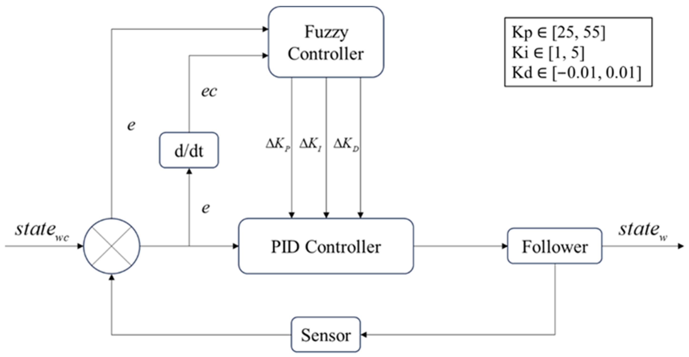
In position-loop control for complex servo systems, the fixed-parameter characteristic of traditional PI controllers impedes effective handling of nonlinear dynamics and external time-varying disturbances. Parameter tuning, typically relying on empirical methods or preliminary frequency-domain analysis, yields only approximate ranges, resulting in response lag, increased overshoot, and limited high-precision positioning performance under dynamic operating conditions. To mitigate these limitations, a fuzzy adaptive PID control strategy (Figure 11) is adopted. This approach constructs a multi-dimensional fuzzy rule base based on initial parameter ranges, taking the position error (e) and error change rate (ec) as fuzzy inputs. These inputs are mapped to fuzzy domains via membership functions, with Mamdani inference dynamically generating PID parameter adjustments Δ K P , Δ K I , Δ K D in real time to achieve online self-tuning of controller gains [22,23].
The fuzzy subsets for the input error e, error change rate ec, and PID parameter adjustments Δ K P , Δ K I , Δ K D in the fuzzy PID controller are uniformly defined as N B , N M , N S , Z O , P S , P M , P B , representing Negative Big, Negative Medium, Negative Small, Zero, Positive Small, Positive Medium, and Positive Big, respectively. Based on long-term engineering expertise and linguistic variable partitioning, the tuning rules for these coefficients are established in Table 3 (with error e as the horizontal axis and error change rate ec as the vertical axis). For extreme working conditions involving high precision and small-angle pointing adjustments, the proportional gain output for the (NB, NB) and (PB, PB) rules is adjusted from the traditional empirical values of NB/PB to ZE. This optimization strategy slightly sacrifices response speed to enhance system stability and robustness.
The introduction of fuzzy adaptive PID control into the position loop is designed to enhance the system’s adaptive capability through real-time dynamic tuning of controller parameters, effectively suppressing the effects of gondola–turntable coupling disturbances and model uncertainties. The proportional gain Kp provides sufficient stiffness during the initial response phase for rapid command tracking and is moderately increased via fuzzy rules near a steady state to further minimize extremely fine steady-state errors. The integral gain Ki is set relatively small initially to prevent integral windup and overshoot, and it is strengthened under fuzzy logic control in the later stage to thoroughly eliminate steady-state deviations on the order of arcseconds. The derivative gain Kd is constrained within a narrow range of [−0.01, 0.01]; it primarily predicts the error trend and applies minimal damping to suppress overshoot during the initial phase, then rapidly recedes in the later stage to avoid sensitivity to high-frequency noise. Through the dynamic coordination of these three parameters via fuzzy rules, the system maintains minimal overshoot, extremely high steady-state accuracy, and an optimized settling time even under complex operating conditions, thereby meeting the stringent requirements of astronomical observation for high-precision pointing and anti-interference stability.

4.2. Control Protection Strategies

To address the stability requirements of the multi-level control system in a near-space balloon-borne astronomical observation platform, two core protection strategies are proposed in this section:
  • Gain adaptation resolves inter-level torque interference phenomena;
  • Anti-windup design suppresses the risk of actuator saturation failure.
These strategies collectively establish a system safety boundary, ensuring robust azimuth pointing control under extreme operating conditions.

4.2.1. Gain Adaptation Processing

The cascaded composite system constitutes an integrated gondola azimuth control system and a tier-2 gondola gimbal pointing system. Owing to the low damping ratio and prolonged period of the gondola torsional mode, the low-frequency oscillation mode may be excited when the reaction torque from the tier-2 system exceeds the compensation capacity of the integrated system, thereby inducing torque conflict phenomena between primary and secondary control levels. In severe cases, this triggers flywheel runaway in the primary system. To address this, a state-criterion-based segmented gain-scheduling mechanism is proposed:
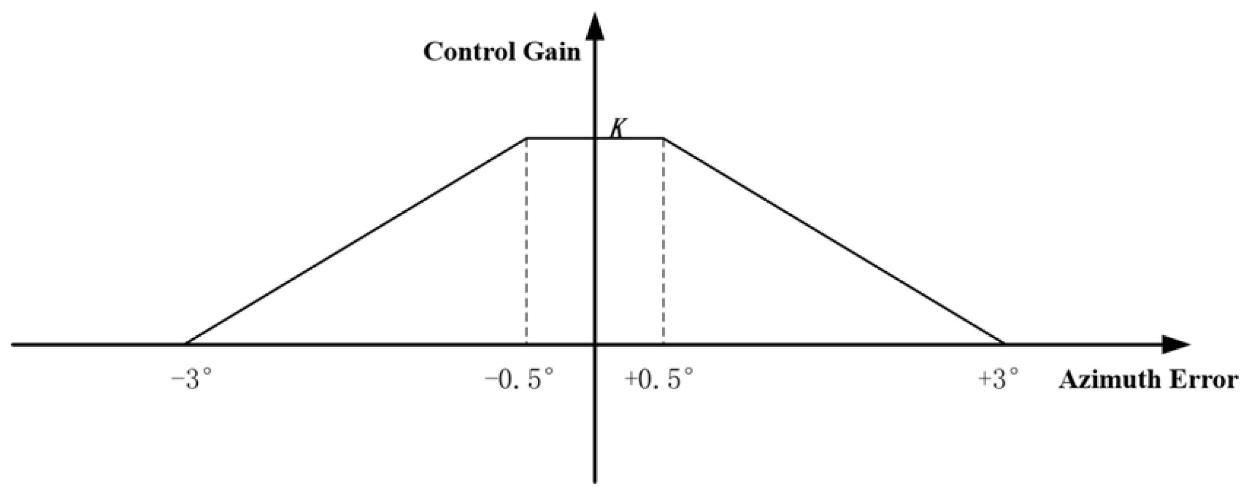
K 0 = 0      Δ θ > 3 ° K Δ θ 0.5 2.5   0.5 ° Δ θ 3 ° K      Δ θ < 0.5 ° ,
where Δ θ denotes the azimuth tracking error, K represents the nominal gain of the tier-2 system, and K 0 is the actual control gain.
The operational strategy is implemented as follows:
  • When the azimuth deviation exceeds 3°, only the integrated gondola azimuth control system is activated, while the tier-2 system remains disabled.
  • When the azimuth deviation enters the 3° range, the tier-2 system engages with low-gain progressive engagement under the integrated system’s operation, avoiding abrupt torque disturbances to the primary control.
  • Once the tier-2 azimuth deviation falls within 0.5°, the tier-2 system operates at its full nominal gain K for precision control.
This adaptive gain-scheduling strategy exhibits a trapezoidal response profile, as shown in Figure 12.
Unlike the stepped-gain approach, which may induce chattering phenomena at step points due to measurement errors, the linear gain strategy significantly reduces the influence of measurement noise on the gain, thereby effectively mitigating tremors. For instance, within the switching interval, based on the 0.1° measurement accuracy of the primary attitude control system, the magnitude of gain variation is merely approximately 4%. After switching to the secondary system, owing to high-precision measurement at the arcsecond level, the impact of noise on the gain becomes almost negligible.
This strategy fundamentally circumvents torque interference risks between the integrated and tier-2 system by state-dependent gain modulation, effectively preventing flywheel runaway caused by reaction torque overload during large-deviation scenarios. It thereby provides critical safety assurance for high-precision pointing control.

4.2.2. Anti-Windup Processing

In the multi-loop architecture of the tier-2 gondola gimbal pointing system, PI controllers containing integral elements are widely adopted for the current loop, velocity loop, and position loop. The inherent characteristic of the integrator causes continuous accumulation of control output under sustained directional deviation. When the actuator enters the saturation zone, the integral term continues to increase. This state cannot be immediately resolved even after error direction reversal, resulting in reset lag and aggravated overshoot, which severely degrades the dynamic response characteristics.
To suppress the integral windup effect, a feedback-based conditional integration anti-windup method is implemented (Figure 13). By dynamically regulating the integral accumulation rate through a real-time feedback path, an integral attenuation mechanism is automatically triggered when the output approaches the physical boundary of the actuator. The actual output of the integrator is expressed as
I ( s ) = 1 s { k i E ( s ) k b [ U ( s ) U ¯ ( s ) ] } = k i s { E ( s ) k b k i [ U ( s ) U ¯ ( s ) ] } ,
where K b denotes the feedback coefficient, satisfying
k b > k i k p = 1 T i ,
or
T b < T i ,
Here, T i = k p k i represents the integral time constant and T b = 1 k b is the winddown time constant.
Figure 13. Control block diagram of anti-windup processing.
Aerospace 12 00821 g013
In this approach, k b functions as an independent variable. When PID coefficients are modified, k b must be adjusted correspondingly to satisfy the above Equation (37). Therefore, in practical system modeling and design, we set k b = 1 γ T i = 1 T b , and the integrator output adopts the following structural form:
I ( s ) = k i s { E ( s ) U ( s ) U ¯ ( s ) γ k p } ,
where γ ( 0.1 , 1 ) , and γ typically takes a value of 0.25 or 0.5 in simulations.
By dynamically suppressing the integral accumulation rate, this method completely eliminates control lag and amplifies overshoot caused by actuator saturation. It ensures controllability maintenance under sustained directional deviations, thereby establishing a protective barrier for stable operation in complex disturbance environments.

5. Simulation Study

To quantitatively validate the arcsecond-level pointing accuracy of the balloon-borne astronomical observation platform under complex dynamic environments, and systematically evaluate the actual efficacy of key technologies—including fiber-optic gyroscope feedback optimization and fuzzy PID control algorithms—in system disturbance rejection, robustness, and tracking precision, the following simulation studies were conducted.

5.1. Simulation Preparation

According to practical engineering requirements, a medium-scale gondola with a mass below 700 kg was adopted for the design. The pitch–axis inertia of the tier-2 gimbal was configured to account for 1/5 to 1/10 of the gondola’s pitch–axis inertia, while its azimuth–axis inertia was set at 1/6 to 1/12 of the gondola’s azimuth–axis inertia. Referencing existing designs, the azimuthal rotation acceleration of the gondola was constrained to 2°/s2. By limiting the azimuth–axis acceleration of the tier-2 gimbal to within 6°/s2, it was ensured that the reaction torque generated by the tier-2 attitude control consistently remained within the compensation range of the primary attitude control system. Detailed simulation parameters are listed in Table A1.
Compliance with the lightweight design requirements of the balloon-borne platform necessitates the closed-loop bandwidth of the velocity loop in the tier-2 gondola gimbal pointing system to be designed at 16 Hz, while the bandwidth of the position loop is set to 8 Hz. The structural mechanical resonance frequency of the gimbal is configured at approximately 40 Hz, corresponding to 2.5 times the velocity loop bandwidth and 5 times the position loop bandwidth. This design effectively prevents resonance between the control system and the elastic modes of the mechanical structure. A structural resonance frequency around 40 Hz simultaneously avoids excessive weight issues caused by overly stringent stiffness requirements.
Both the primary reaction wheel, torque compensator, and the tier-2 gondola gimbal shaft motors employ brushless permanent magnet torque motors in a direct-drive configuration. This design eliminates backlash and hysteresis phenomena associated with geared transmission systems while simultaneously ensuring high structural stiffness and a fundamental natural frequency of the system. Reference parameters of the motors adopted in this simulation study are detailed in Table A2.
Considering the lightweight design requirements of the balloon-borne platform, the closed-loop bandwidth of the velocity loop in the tier-2 gondola gimbal pointing system is designed at 16 Hz, while the position loop bandwidth is set to 8 Hz. The structural mechanical resonance frequency of the gimbal is designed at approximately 40 Hz, which is 2.5 times the velocity loop bandwidth and 5 times the position loop bandwidth. This design effectively prevents resonance between the control system and the elastic modes of the mechanical structure. A structural resonance frequency around 40 Hz also avoids excessive weight issues caused by overly stringent stiffness requirements.
To enhance the fidelity of the simulation model to actual scenarios, encoder measurement error, primary attitude sensor measurement error, tier-2 precision attitude sensor error, motor static friction, motor dynamic friction, and external disturbance torque were incorporated into the simulation system based on real-world engineering conditions. Parameters for sensors and motors were directly computed from numerical values (Table A3).
Considering the simulation environment at a near-space altitude of 35 km (atmospheric density ρ ), the relative velocity between the balloon-borne gondola and the atmosphere is assumed to be low. Given a maximum relative wind speed v m , aerodynamic frontal area A p , and aerodynamic drag coefficient C d , aerodynamic disturbance forces F a are calculated by Newton’s drag law:
F a = 1 2 ρ v m 2 C d A p   ,
Accounting for structural asymmetry, let the eccentricity distance between the aerodynamic load application point and the center of mass be d p . The wind-induced disturbance torque M p is then expressed as
M p = F a d p ,
For a 60 kg telescope payload, assuming its effective frontal area under maximum relative wind speed v m is A t , the aerodynamic disturbance force F t is defined as
F t   = 1 2 ρ v m 2 C d A t   ,
Due to optical component mass offset, let the eccentricity distance of the payload application point be d t . The wind-induced disturbance torque M t is
M t   = F t d t   ,
Based on the above calculations and combining the aerodynamic disturbance parameters (Table A4), the maximum result is as follows: the wind-induced disturbance torque acting on the integrated gondola azimuth control system M p = 0.5 Nm @ 0.3 Hz , and the external disturbance torque acting on the tier-2 gondola gimbal pointing system M t   = 0.12 Nm @ 0.7 Hz .
The azimuth channel control system of the balloon-borne observatory was modeled in Simulink, as illustrated in Figure 14. This simulation framework integrates three core subsystems:
  • Gondola–Gimbal Dynamics Model: Implements the dynamics equations derived in Section 3, utilizing predefined disturbance profiles and inertia parameters from appended tables to characterize rigid-body interactions between the payload and gimbal platform;
  • Gondola Anti-Twist Decoupling Controller: Accepts gondola azimuth motion feedback and balloon tether twist angle as inputs, generating anti-twist motor torque commands to neutralize azimuthal torsion through real-time cable-induced disturbance compensation;
  • Integrated Azimuth Control Architecture:
    • Flywheel Controller: Regulates overall gondola orientation via synergistic actuation with the anti-twist controller;
    • Gimbal Azimuth Controller: Stabilizes high-precision pointing of the inner frame;
    • Master Azimuth Controller: Fuses coarse azimuth references from the flywheel subsystem with fine-pointing feedback from the gimbal.
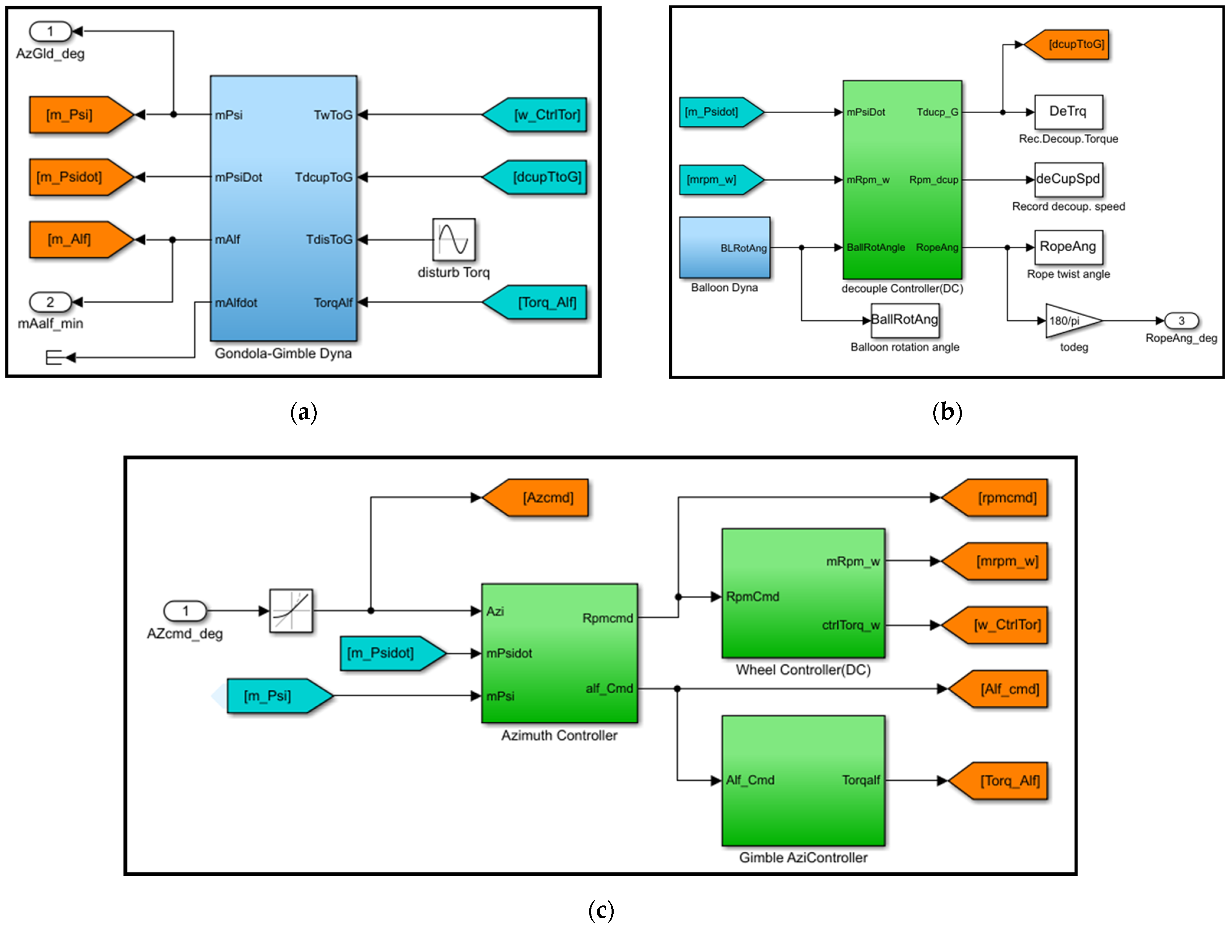
Figure 14. The model of the balloon-borne observatory’s azimuth channel control system. (a) gondola–gimbal dynamics model; (b) decoupling controller for gondola reaction torque; (c) integrated azimuth control architecture (main, gimbal, and wheel controllers).
Aerospace 12 00821 g014
The model employs a fixed-step solver, ode14x (step size: 0.001 s), to ensure highly deterministic simulation behavior at discrete time steps, thereby providing a reliable and consistent simulation environment for the validation of system disturbance suppression algorithms. The solver achieves a balance between computational complexity and accuracy through its extrapolation algorithm, making it particularly suitable for the dual requirements of simulation efficiency and stability in this model. A sinusoidal torque disturbance with a frequency of 1 rad/s is applied to simulate the continuous impact of periodic interference sources encountered in real-world scenarios, enabling a comprehensive evaluation of the controller’s suppression capability and robustness under disturbances of varying phases and amplitudes. To emulate gradually varying command signals during practical operation, a linear ramp input with a slope constrained to ±3 units per second is selected. This input mode effectively tests the controller’s tracking performance under slowly varying references while avoiding transient overshoot or actuator saturation issues caused by abrupt input changes.

5.2. Simulation Verification

The integrated gondola azimuth control system, serving as the foundational stabilization layer for balloon-borne astronomical observation platforms, achieves azimuth pointing accuracy through a synergistic torque distribution mechanism between reaction wheels and the torque compensator. The reaction wheels generate active control torque via momentum exchange to drive the gondola rotation, while the torque compensator simultaneously isolates balloon-body rotational disturbances and produces unloading torque to prevent wheel saturation, forming a closed-loop complementary control architecture. The core design objective of this system lies in suppressing the inherent low-frequency, large-azimuth deviations (>1°) of balloon platforms, thereby providing a preliminarily stabilized base environment for the tier-2 gondola gimbal pointing system.
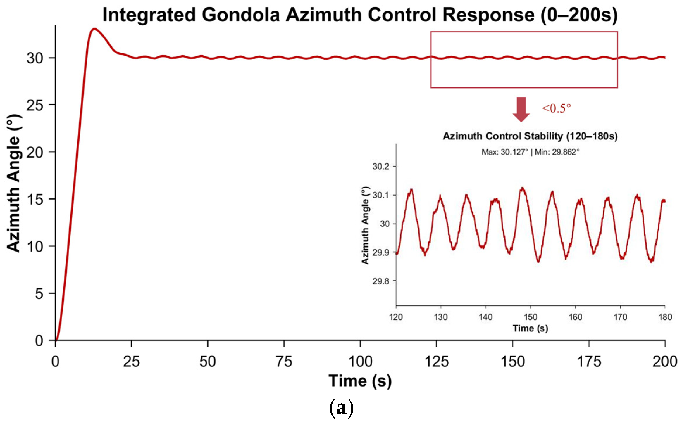
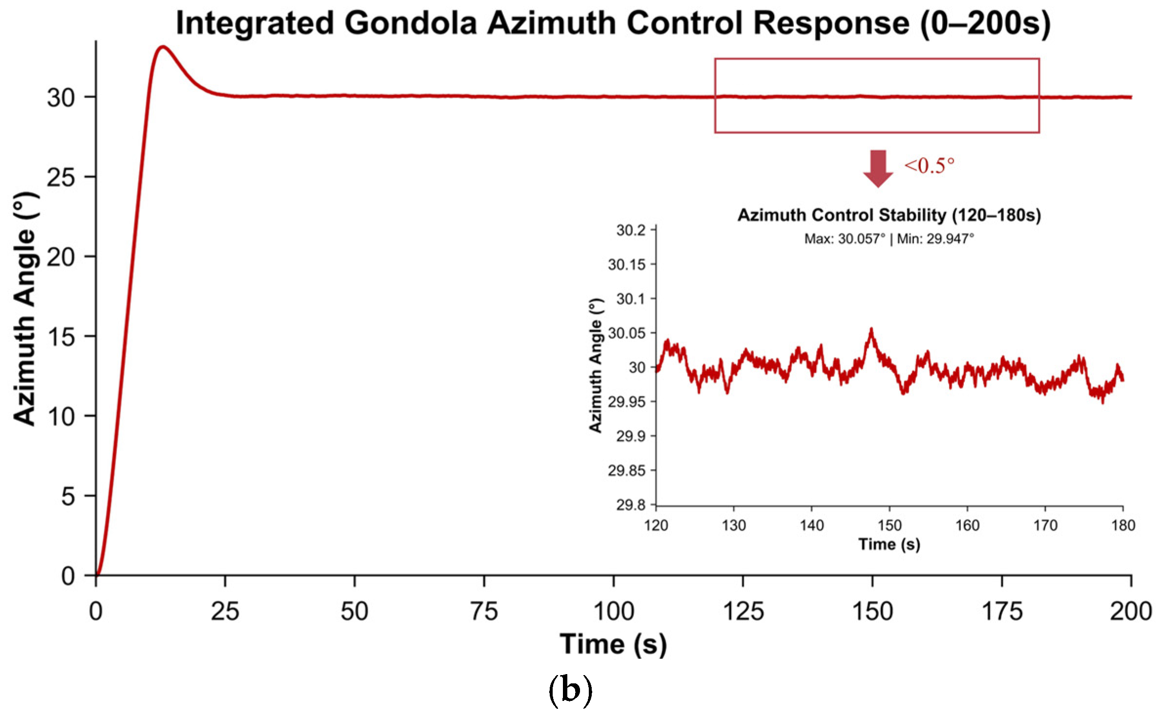
When executing a 30° azimuth step command, Figure 15’s simulation results demonstrate the integrated gondola azimuth control system’s full 360° attitude regulation capability. However, its precision enhancement is constrained by two fundamental physical bottlenecks: (1) the inherent frequency-response limits of mechanical actuators restrict dynamic tracking performance against high-frequency disturbances, and (2) the low-stiffness characteristics of the gondola–balloon chain structure induce significant resonance phenomena.
Given the high sensitivity of arcsecond-level pointing accuracy to minor disturbances, external mechanical vibrations and material deformations cannot be neglected. To verify the system’s disturbance rejection robustness under stringent suppression requirements, a periodic sinusoidal torque disturbance is introduced. Under such conditions, the residual error manifests as low-amplitude oscillations.
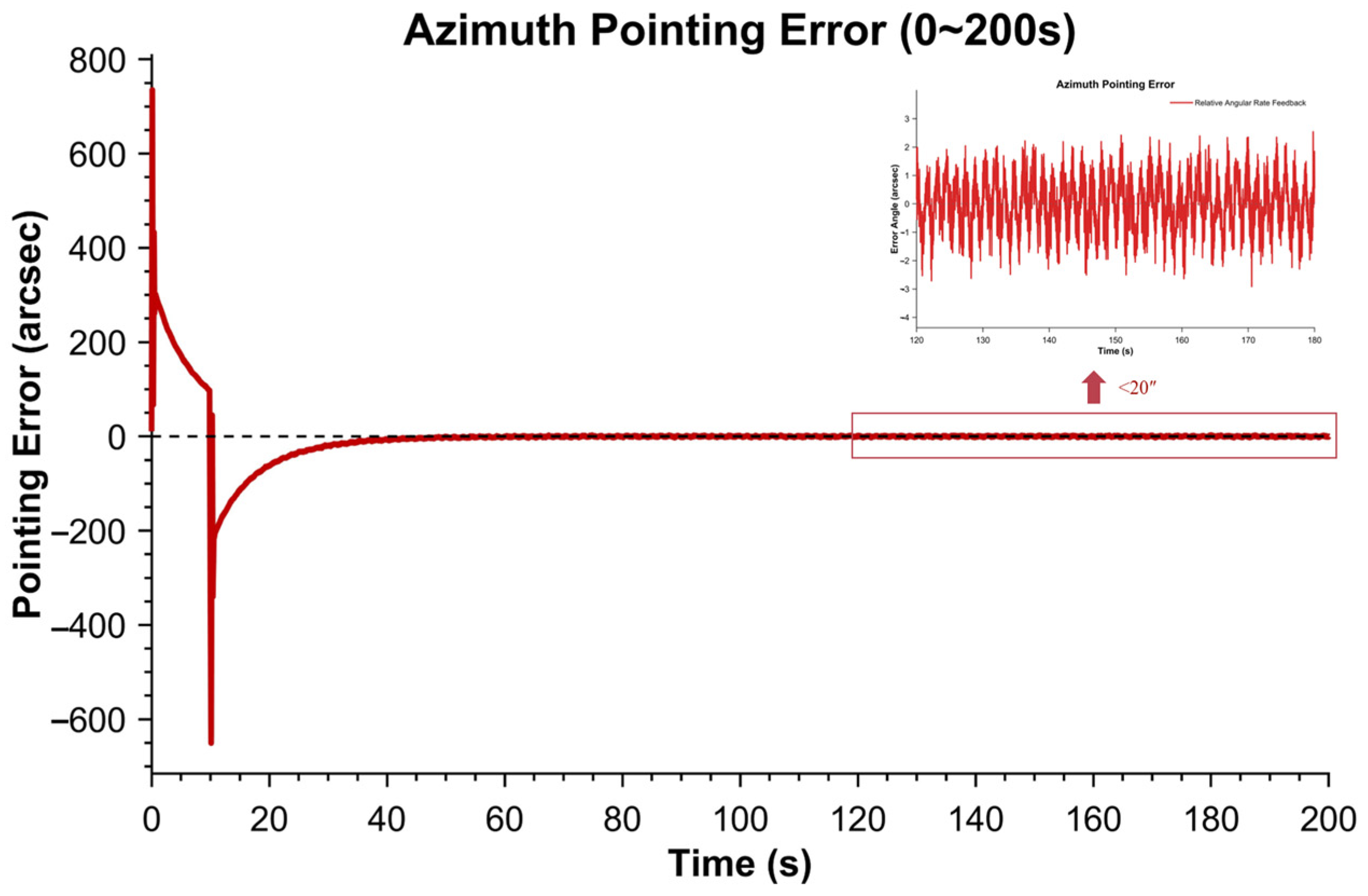
Since actuator bandwidth and structural stiffness are intrinsic hardware properties unalterable by control strategies, overcompensating for high-frequency disturbances or low-frequency resonances through algorithms may inadvertently excite unmodeled dynamics and instability. Consequently, the fundamental approach to achieving arcsecond-level accuracy relies on a hierarchical control architecture: the integrated gondola azimuth control system suppresses large-scale deviations to establish a preliminarily stabilized base (≤0.5°), while the tier-2 gondola gimbal pointing system subsequently compensates for residual errors via gain-adaptive strategies, ultimately realizing a <20″ pointing accuracy (Figure 16).
The tier-2 gondola gimbal pointing system exhibits a double-peak overshoot characteristic upon activation, a phenomenon stemming from the system’s dynamic response to linear command inputs: the first overshoot primarily results from insufficient control gain during the initial startup phase, which fails to effectively overcome static friction, leading to a temporary increase in error before resuming a decreasing trend; the second overshoot is mainly induced by the integral element during abrupt changes in the control command, where integral action accumulates error and causes excessive compensation. Although this linear command design introduces overshoot, it effectively avoids the instantaneous torque impact and actuator saturation risk associated with step commands, thereby achieving a smooth transition while ensuring system stability. Furthermore, the overshoot amplitude remains within the acceptable precision range of the integrated gondola azimuth control system, and the system converges within 40 s, meeting engineering application requirements.
The core functionality of the system resides in achieving gondola base motion decoupling through an “outer pitch + inner azimuth” structure, while employing a triple-loop control architecture. This architecture comprises a current loop for precise motor torque tracking, a velocity loop for high-frequency disturbance suppression, and a position loop guaranteeing arcsecond-level positioning accuracy. To enhance control precision, comparative simulations were conducted for velocity loop feedback control and position loop algorithm design.

5.2.1. Velocity Loop Feedback Control Verification

In the azimuth control simulation of the tier-2 gondola gimbal pointing system, the velocity loop feedback control modes were initially validated (Figure 17). Comparative simulations were conducted for two feedback strategies: encoder-based relative angular velocity feedback, where rate information is derived from the differential of motor shaft displacement; and fiber-optic gyroscope, absolute inertial angular velocity feedback, which directly acquires angular motion data of the carrier in inertial space.
Simulation results demonstrate that the encoder-based feedback achieves a pointing control accuracy of 20″, while the introduction of fiber-optic gyroscope feedback capturing absolute inertial angular velocity data improves accuracy to 5″. This indicates that gyroscopic feedback suppresses external disturbances by providing absolute inertial motion information, thereby better satisfying high-precision pointing requirements for astronomical observations.

5.2.2. Position Loop Algorithm Optimization Verification

To address the parameter rigidity limitation of conventional PID strategies in coping with nonlinear disturbances during tier-2 gondola gimbal pointing system position loop control, this paper introduces an adaptive fuzzy PID algorithm to achieve dynamic parameter tuning. This design dynamically adjusts controller gains through fuzzy rules, thereby resolving the fundamental trade-off between disturbance rejection and steady-state accuracy in high-precision pointing scenarios.
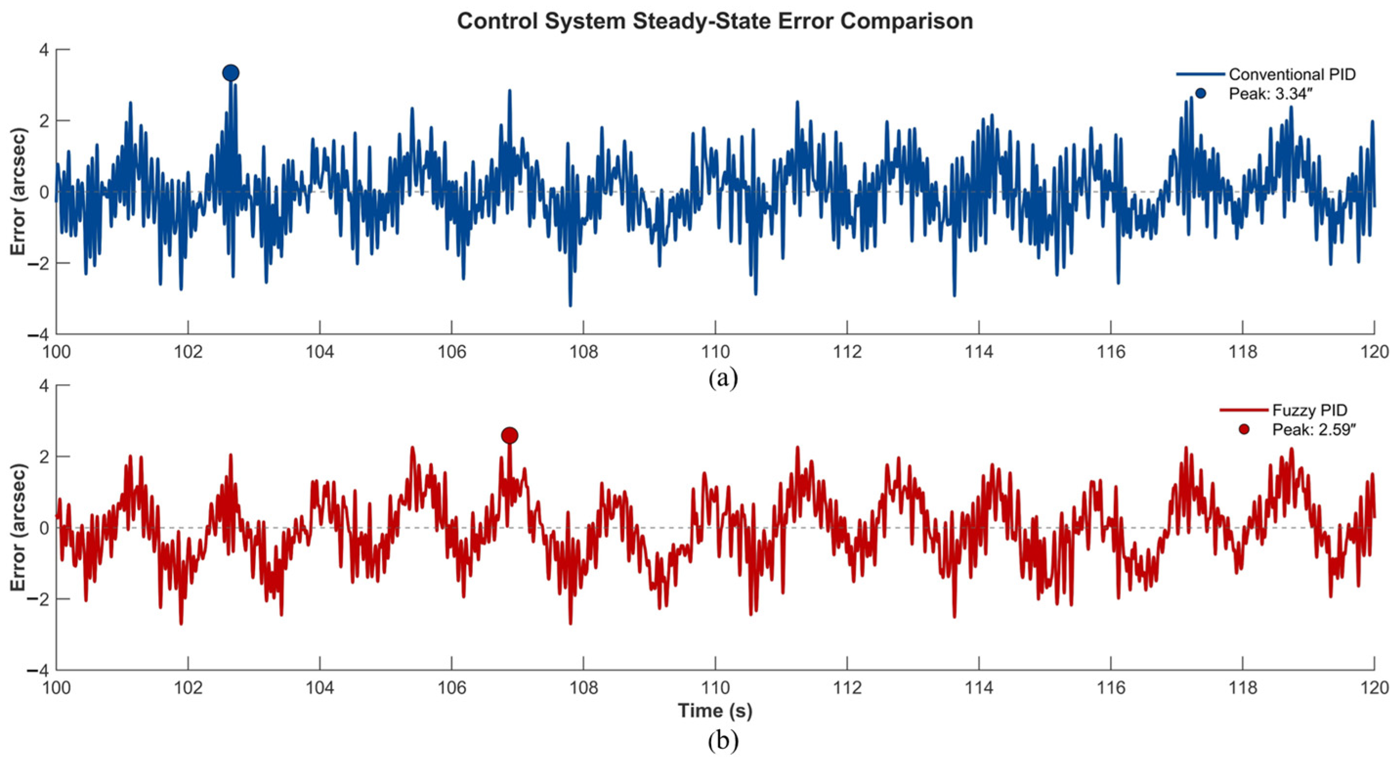
Simulation results (Figure 18) demonstrate that the proposed algorithm achieves a steady-state pointing accuracy superior to 5″, satisfying the core requirement of azimuth control for the tier-2 gondola gimbal pointing system.
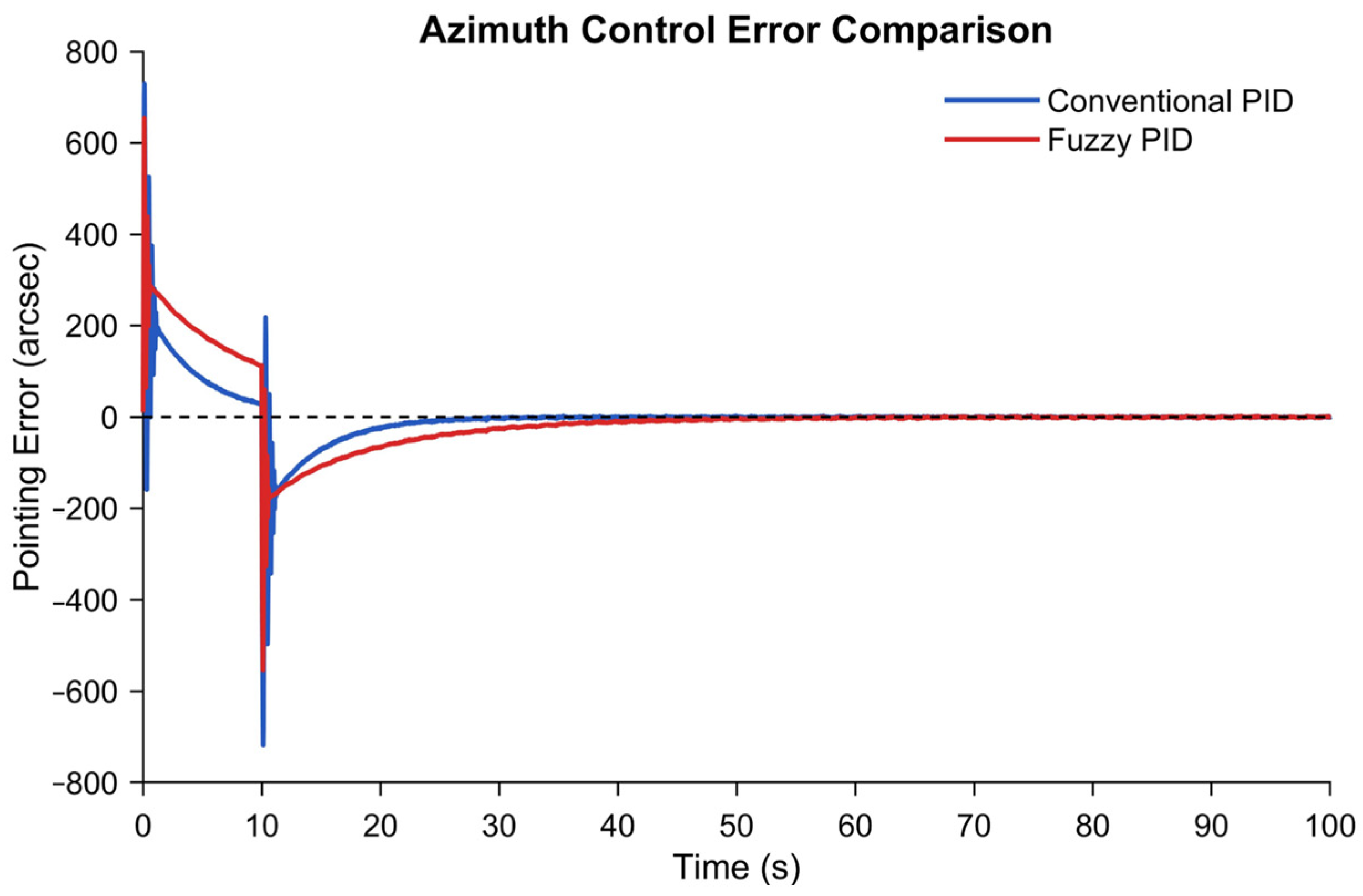
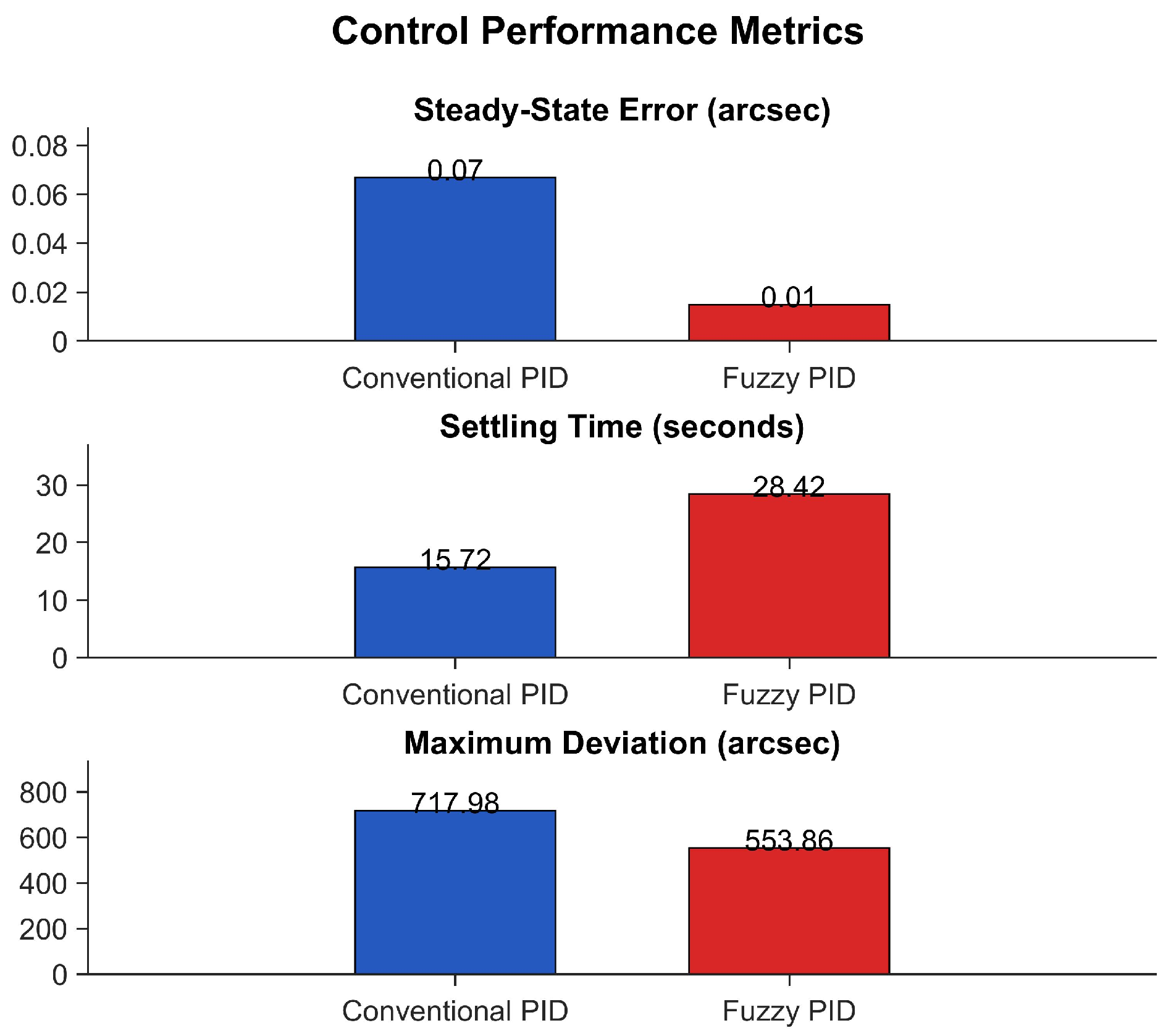
To systematically evaluate the performance advantages of fuzzy PID control in both the integrated gondola azimuth control system and the tier-2 gondola gimbal pointing system, this study conducts quantitative analysis through azimuth control error comparison (Figure 19) and multi-dimensional performance metrics (Figure 20). These analyses reveal its breakthrough improvements in steady-state accuracy and disturbance rejection capability.
Simulation results demonstrate that compared with conventional PID control, the fuzzy PID control achieves a significant enhancement in steady-state pointing accuracy while substantially reducing the maximum disturbance-induced deviation. Although its settling time is prolonged, the stringent demand for steady-state accuracy in astronomical observations prioritizes precision over rapid response. This control strategy thereby systematically optimizes the pointing stability of high-value payloads at a limited cost in dynamic response performance.

5.2.3. Robustness Verification of Pointing Accuracy Under Payload Inertia Uncertainty

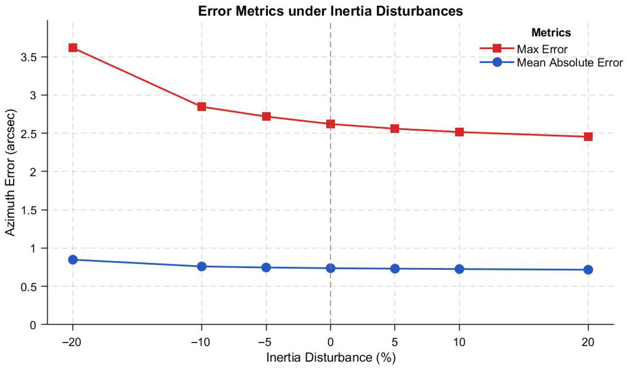
To validate the robust performance under payload parameter uncertainty, seven perturbation comparison tests were conducted for the moment of inertia parameters of the tier-2 gondola gimbal pointing system, encompassing the nominal condition and inertia deviations of ±5%, ±10%, and ±20%. This ±20% perturbation range originates from the payload weight-inertia tolerance standard threshold defined by the platform, which verifies inertia deviation adaptability when different teams deploy medium–small telescope payloads. Through multi-dimensional perturbation scenario validation, a design margin in multi-payload compatibility and pointing accuracy robustness is ensured (Figure 21).
Simulation results demonstrate that under varying inertia perturbations, an increase in load inertia reduces the equivalent damping ratio, resulting in elevated overshoot in step responses. Furthermore, all perturbation scenarios converge to the steady-state band within the specified time, confirming the strong robustness of the controller within the ±20% inertia variation range.
To quantitatively assess the impact mechanism of payload inertia perturbations on pointing accuracy, azimuth pointing error comparison results under different inertia perturbations were obtained during the stable phase (100–120 s) (Figure 22).
Combined with statistical metric evaluation of pointing accuracy (Figure 23), the results empirically show that during the 100–120 s steady-state observation window, all scenarios exhibit azimuth errors converging within the ±5″ accuracy threshold. The system demonstrates strong robustness within ±20% inertia perturbations, satisfying compatibility requirements for diverse telescope payload specifications.
Simulation verification of the tier-2 gondola gimbal pointing system demonstrates that a multi-level cooperative control architecture achieves precise pointing objectives. After the integrated gondola azimuth control system stabilizes platform pointing accuracy below 0.5°, the tier-2 system is dynamically activated based on a gain-adaptive strategy. An “outer pitch–inner azimuth” structure is implemented to decouple base motion, while dynamic performance is enhanced through current–velocity–position triple-loop control. In velocity-loop validation, fiber-optic gyroscope feedback capturing absolute inertial angular velocity demonstrated a superior performance to encoder-based relative feedback, effectively suppressing external disturbances. For the position loop, an adaptive fuzzy PID algorithm was introduced, simultaneously improving steady-state accuracy and disturbance rejection capability while meeting stringent requirements for astronomical observation precision. Robustness tests further confirm stable pointing under ±20% payload inertia perturbations, ensuring compatibility with diverse telescope payload specifications.

6. Conclusions

This study addresses the multi-level coupling and disturbance suppression challenges in azimuth pointing control for near-space balloon-borne astronomical platforms, proposing a systematic solution with the following key achievements:
  • A unified nonlinear dynamic model for the azimuth channel was established for the first time, accurately characterizing the inertial coupling effects between the integrated gondola azimuth control system and the tier-2 gondola gimbal pointing system, thereby laying a theoretical foundation for control strategy design.
  • A precision control algorithm was constructed through fiber-optic gyroscope velocity-loop feedback and an adaptive fuzzy PID position loop, achieving high disturbance rejection and strong robustness. This was supplemented by a dual-protection strategy integrating gain adaptation and anti-windup constraints, ensuring stable operation of the multi-level control system under extreme conditions.
  • High-fidelity multi-condition simulations verified that the proposed control system attains < 20″ steady pointing accuracy under typical wind disturbances (0.7 Hz) and sensor noise, while maintaining control errors below 5″ under ±20% payload inertia perturbations, providing a rigorously validated theoretical design paradigm for near-space astronomical observation platforms.
Although this study provides encouraging simulation results, several limitations remain: the current research is in the design stage, and the conclusions rely on high-fidelity simulations. While these simulations offer critical insights into the system’s performance under various conditions, they cannot fully capture all the complexities and unforeseen factors in a physical implementation. Therefore, to further validate and advance this work, we will actively pursue Hardware-in-the-Loop (HIL) semi-physical simulation experiments in future efforts. Subsequently, we plan to conduct suspension experiments. These experiments will provide the most authentic assessment of the platform’s pointing performance and robustness in an environment closest to its intended operational scenario. This progression—from simulation to semi-physical simulation, and finally to physical experimentation—forms a logical pathway for the development and refinement of this technology, ensuring its readiness for practical scientific applications in near-space astronomical observation.
This study provides reliable technical support for scientific missions such as near-space astronomical observation. The outcomes not only significantly enhance the azimuth pointing performance of balloon-borne platforms but also establish a crucial reference benchmark for advancing precision pointing technologies for high-value near-space payloads, demonstrating broad prospects for engineering applications.

Author Contributions

Conceptualization, Y.C., J.Z., and W.H.; methodology, Y.C., J.Z., and W.H.; software, Y.C. and J.Z.; validation, Y.C. and Y.L. (Yijian Li); formal analysis, Y.C. and Y.L. (Yijian Li); investigation, Y.C. and Y.L. (Yongqi Liu); resources, Y.C.; data curation, Y.C.; writing—original draft preparation, Y.C.; writing—review and editing, Y.C., J.Z., and Y.L. (Yijian Li); visualization, Y.C.; supervision, J.Z. and W.H.; project administration, J.Z. and W.H. All authors have read and agreed to the published version of the manuscript.

Funding

The research is funded by National Natural Science Foundation of China, 52227811, and National Key R&D Program of China, 2022YFB3207300. The article processing charge was funded by the Aerospace Information Research Institute, Chinese Academy of Sciences.

Data Availability Statement

The original contributions presented in this study are included in the article, and further inquiries can be directed to the corresponding author.

Conflicts of Interest

The authors declare no conflicts of interest.

Appendix A

Appendix A presents the parameter configurations used in the simulations.
Table A1. Near-space balloon-borne astronomical observation platform system simulation: general parameter table.
ParametersNumerical ValuesParameter Application Notes
Nominal level-flight altitude35 kmBalloon Dyna model parameter
Balloon sphere volume10,000 m3
Balloon sphere height18.3 m
Balloon sphere maximum diameter30.5 m
Balloon sphere volume0.45
Horizontal added mass coefficient of sphere0.7
Telescope gondola suspension point position L12.5 m
Distance from gondola CG to suspension point L23 m
Suspension cable length L350 m
Equivalent stiffness of suspension cable1.372 N·m/rad
Reference structural gross weight672 kgTotal mass of gondola and gimbal system
Reference suspended weight (gondola weight)600 kg
Gondola moment of inertia about X-axis (through CG) Jox200 kg·m2Inertia tensor of mounting-base frame o x o y o z o
Gondola moment of inertia about Y-axis (through CG) Joy200 kg·m2
Gondola moment of inertia about azimuth axis (Z-axis) Joz150 kg·m2
Telescope body moment of inertia (X-axis) Jix8 kg·m2Inertia tensor of pointing-axis frame o x i y i z i
Telescope body moment of inertia (Y-axis) Jiy12 kg·m2
Telescope body moment of inertia (Z-axis) Jiz12 kg·m2
Inner gimbal moment of inertia (X-axis) Jmx12 kg·m2Inertia tensor of inner-gimbal frame o x m y m z m
Inner gimbal moment of inertia (Y-axis) Jmy8 kg·m2
Inner gimbal moment of inertia (Z-axis) Jmz8 kg·m2
Telescope gravity G600 NDerived from payload mass: G = mg (g = 9.8 m/s2)
Table A2. Reference parameters of motors adopted in the simulation study.
Parameter CategoriesParametersNumerical Values
Rated PerformanceRated Torque5 N·m
Rated Speed30 rpm
Rated Voltage24 V
Rated Current4 A
Electrical ParametersArmature Resistance4.74 Ω
Armature Inductance0.019 H
Back-EMF Constant1.72 V·s/rad
Torque Constant1.32 N·m/A
Mechanical ParametersStatic Friction Torque0.04 N·m
Dynamic Friction Coefficient0.01 N·m
Table A3. System simulation core performance parameters.
ParametersNumerical Values
Triaxial FOG Accuracy0.01°/h
GNSS/INS AccuracyAzimuth: ≤0.05°
Pitch/Roll: ≤0.03°
Gyro: 0.01°/h
Velocity: ≤0.1 m/s
Position: 5 m (CEP)
Reaction Wheel/Torque MotorTorque: 0.05 N·m
Dynamic Friction: 0.02 N·m·s/rad
Gimbal Servo MotorTorque: 0.04 N·m
Dynamic Friction: 0.02 N·m·s/rad
Table A4. Aerodynamic disturbance parameters.
ParametersNumerical Values
Atmospheric density ρ 0.00675~0.00848 kg/m3
Maximum relative wind speed vm9 m/s
Gondola aerodynamic frontal area Ap4 m2
Aerodynamic drag coefficient Cd0.7
Aerodynamic disturbance force on gondola Fa0.765~0.962 N
Eccentricity distance between aerodynamic load application point and center of mass dp0.5 m
Effective frontal area of telescope assembly At0.5 m2
Aerodynamic disturbance force on telescope assembly Ft0.095~0.120 N
Eccentricity distance of telescope payload application point dt1 m

References

  1. Huang, W.; Zhang, X.; Li, Z.; Wang, S.; Huang, M.; Cai, R. Development status and application prospect of near space science and technology. Sci. Technol. Rev. 2019, 37, 46–62. [Google Scholar]
  2. Li, Y.; Huang, W.; Zhou, J.; Zhang, X.; Zhang, H. Development status and prospects of near space observatories. Chin. J. Space Sci. 2024, 44, 1068–1085. [Google Scholar] [CrossRef]
  3. Pascale, E.; Ade, P.A.; Bock, J.J.; Chapin, E.L.; Chung, J.; Devlin, M.J.; Dicker, S.; Griffin, M.; Gundersen, J.O.; Halpern, M.; et al. The balloon-borne large aperture submillimeter telescope: BLAST. Astrophys. J. 2008, 681, 400–414. [Google Scholar] [CrossRef]
  4. Rhodes, J.; Dobke, B.; Booth, J.; Massey, R.; Liewer, K.; Smith, R.; Amara, A.; Aldrich, J.; Berge, J.; Bezawada, N.; et al. Space-quality data from balloon-borne telescopes: The High Altitude Lensing Observatory (HALO). Astropart. Phys. 2012, 38, 31–40. [Google Scholar] [CrossRef]
  5. Kassarian, E.; Sanfedino, F.; Alazard, D.; Evain, H.; Montel, J. Modeling and stability of balloon-borne gondolas with coupled pendulum-torsion dynamics. Aerosp. Sci. Technol. 2021, 112, 106607. [Google Scholar] [CrossRef]
  6. Shoji, Y.; Tanabe, T.; Sato, N. Highly precise pointing control system on a balloon-borne telescope for optical observations of planets. In Proceedings of the 8th International Symposium on Space Technology and Science, Tokyo, Japan, 5–12 June 2010; pp. Pm_15–Pm_20. [Google Scholar]
  7. Fairbrother, D.A. The NASA Balloon Program—Positioning for the future. In Proceedings of the AIAA Balloon Systems Conference, Dallas, TX, USA, 15–19 June 2015. [Google Scholar]
  8. Lecinski, A.; Card, G.; Knölker, M.; Hardy, B. The design and performance of the gondola pointing system for the Sunrise II balloon-borne stratospheric solar observatory. J. Astron. Instrum. 2017, 6, 1740007. [Google Scholar] [CrossRef]
  9. Kassarian, E.; Sanfedino, F.; Alazard, D.; Montel, J.; Chevrier, C.A. Robust line-of-sight pointing control on-board a stratospheric balloon-borne platform. arXiv 2021, arXiv:2112.10458. [Google Scholar]
  10. Romualdez, L.J. Design, Implementation, and Operational Methodologies for Sub-Arcsecond Attitude Determination, Control, and Stabilization of the Super-Pressure Balloon-Borne Imaging Telescope (SuperBIT). Ph.D. Thesis, University of Toronto, Toronto, ON, Canada, 2018. [Google Scholar]
  11. Yajima, N.; Kogaji, S.; Hashino, K. Research on the direction control system of a balloon-borne telescope. In Technical Report; Mechanical Engineering Laboratory, AIST: Tsukuba, Japan, 1986; Report No. 86-015. [Google Scholar]
  12. Shoji, Y.; Tanabe, T.; Sato, N. FUJIN-2: Balloon borne telescope for optical observation of planets. In Proceedings of the 14th International Symposium on Space Technology and Science, Tokyo, Japan, 3–9 July 2016; pp. Pk_95–Pk_102. [Google Scholar]
  13. Lin, J.; Song, T.; Sun, M.; Zhang, T.; Xu, F.; Wang, J.; Fu, Y.; Li, Y.; Kang, K.; Huang, M.; et al. A 50 mm balloon-borne white-light coronagraph: I. Basic structure and experiments on the ground. Sci. Sin.-Phys. Mech. Astron. 2023, 53, 259611. (In Chinese) [Google Scholar] [CrossRef]
  14. Ye, X.M. Study on High-Accuracy Attitude Control and Pointing Technology of a Large Balloon-Borne Solar Telescope. Ph.D. Thesis, National Astronomical Observatories, Chinese Academy of Sciences, Beijing, China, 1999. [Google Scholar]
  15. Stuchlik, D. The wallops arc second pointer-a balloon borne fine pointing system. In Proceedings of the AIAA Balloon Systems Conference, Dallas, TX, USA, 15–19 June 2015. [Google Scholar]
  16. Stuchlik, D. The NASA Wallops Arc-Second Pointer (WASP) system for precision pointing of scientific balloon instruments and telescopes. In Proceedings of the AIAA Balloon Systems Conference, Denver, CO, USA, 5–9 June 2017. [Google Scholar]
  17. Li, Y.; Zhou, J.; Zhang, X.; Zhao, C.; Xu, G. Dynamic modeling and control analysis of pitch/roll channels in the ball cabin system. J. Beijing Univ. Aeronaut. Astronaut. 2024. (In Chinese) [Google Scholar] [CrossRef]
  18. Li, Y.J.; Zhou, J.H.; Zhang, X.J. Dynamic modeling and parameter identification of azimuth channel for balloon gondola system. J. Beijing Univ. Aeronaut. Astronaut. 2024, 50, 2001–2008. [Google Scholar]
  19. Zhang, D.W.; Zhou, J.H.; Huang, W.N. Design of simplified anti-twist control system for high-altitude balloon gondola attitude control. Aerosp. Control 2016, 34, 76–82. [Google Scholar]
  20. Li, Y.J. Research on Attitude Control Technology of Balloon-Borne Gondola Based on Multi-Sensor Fusion. Master’s Thesis, University of Chinese Academy of Sciences, Beijing, China, 2023. [Google Scholar]
  21. Yin, T.Z. Research on Lightweight Attitude Control System for Small and Medium-Sized Gondolas. Master’s Thesis, University of Chinese Academy of Sciences, Beijing, China, 2024. [Google Scholar]
  22. Tang, K.; Man, K.F.; Chen, G.; Kwong, S. An optimal fuzzy PID controller. IEEE Trans. Ind. Electron. 2001, 48, 757–765. [Google Scholar] [CrossRef]
  23. Phu, N.D.; Hung, N.N.; Ahmadian, A.; Senu, N. A new fuzzy PID control system based on fuzzy PID controller and fuzzy control process. Int. J. Fuzzy Syst. 2020, 22, 2163–2187. [Google Scholar] [CrossRef]
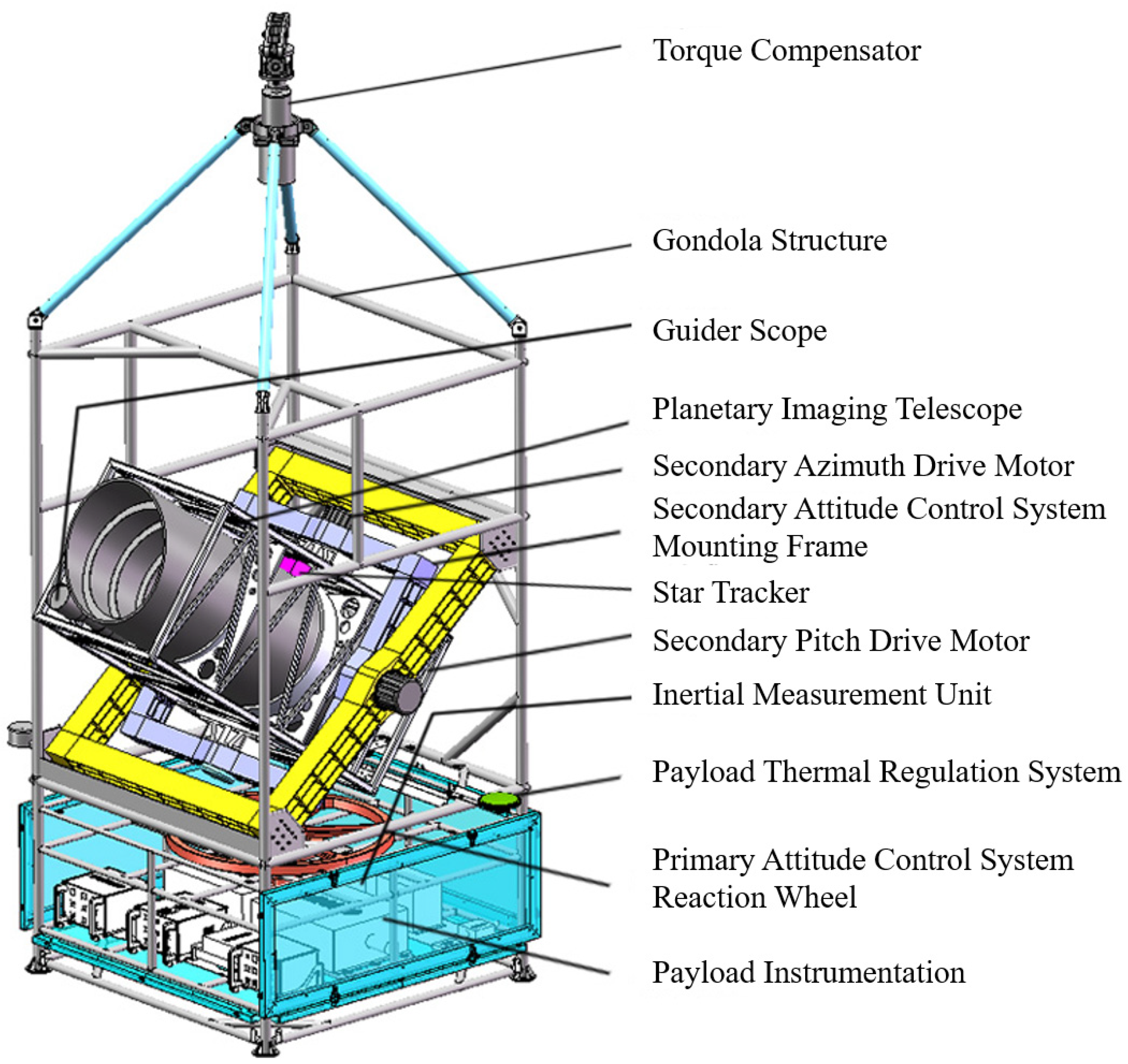
Figure 1. Universal near-space observatory: main structural diagram.
Aerospace 12 00821 g001
Figure 2. Architecture diagram for near-space balloon-borne astronomical observatory.
Aerospace 12 00821 g002
Figure 4. Tier-2 gimbal structure schematic diagram.
Aerospace 12 00821 g004
Figure 5. Simplified model of secondary gimbal platform system.
Aerospace 12 00821 g005
Figure 6. Attitude control system for near-space balloon-borne astronomical observatory platform: block diagram.
Aerospace 12 00821 g006
Figure 7. Tier-2 gondola gimbal pointing system: block diagram.
Aerospace 12 00821 g007
Figure 8. Open-loop transfer function block diagram of the azimuth channel in the tier-2 gondola gimbal pointing system.
Aerospace 12 00821 g008
Figure 9. Feedback control design for the velocity loop.
Aerospace 12 00821 g009
Figure 10. Two different measuring instruments: (a) absolute optical encoder; (b) fiber-optic gyroscope.
Aerospace 12 00821 g010
Figure 11. Block diagram of fuzzy PID control structure.
Aerospace 12 00821 g011
Figure 12. Trapezoidal gain-scheduling response profile for tier-2 gimbal adaptive control.
Aerospace 12 00821 g012
Figure 15. (a) Integrated gondola azimuth control curve without disturbance; (b) integrated gondola azimuth control curve with introduced disturbance.
Aerospace 12 00821 g015aAerospace 12 00821 g015b
Figure 16. Diagram of Tier-2 gondola gimbal pointing control error curve.
Aerospace 12 00821 g016
Figure 17. Secondary gimbal platform pointing error (red: relative angular rate feedback; blue: inertial angular rate feedback).
Aerospace 12 00821 g017
Figure 18. Azimuth pointing error comparison: (a) conventional PID steady-state error; (b) fuzzy PID steady-state error.
Aerospace 12 00821 g018
Figure 19. PID vs. fuzzy PID azimuth control error comparison.
Aerospace 12 00821 g019
Figure 20. PID vs. fuzzy PID control performance metrics.
Aerospace 12 00821 g020
Figure 21. Simulation results of ±20% payload inertia variation.
Aerospace 12 00821 g021
Figure 22. Azimuth error under different inertia perturbations.
Aerospace 12 00821 g022
Figure 23. Statistical data of azimuth error under inertia perturbations.
Aerospace 12 00821 g023
Table 1. Precision requirements for observational tasks.
Observation TypeTracking AccuracyTechnical Challenges
High-resolution Optical<0.1″Adaptive optics; high-speed feedback
Spectroscopic0.5″–1″Slit stabilization; real-time calibration
Time-domain Astronomy1″–2″Rapid-response control systems
Planetary Surface Imaging<0.05″Dual star/target alignment
Galaxy/Nebula Studies<0.1″–0.3″High-precision polar alignment
Table 2. Hierarchical accuracy requirements for attitude control in observation missions.
Mission/SystemPrimary Control AccuracySecondary Pointing AccuracyTertiary Image Stabilization Accuracy
Japan FUJIN *0.5°1′0.1″
China Balloon-borne Coronagraph0.5°20″1″
China BST0.1°20″/
NASA WASP *1~3°1″0.1″
Germany SUNRISE26″0.04″
* Table 2 highlights two critical cases: (1) Japan’s FUJIN mission achieved a secondary pointing accuracy of 1 arcminute and a tertiary stabilization accuracy of 0.1 arcsecond, imposing extreme demands on tertiary control; (2) the NASA WASP system attained a primary control accuracy of 1–3° with a secondary pointing accuracy of 1 arcsecond, presenting significant challenges for secondary control.
Table 3. Fuzzy rule table for ΔKP, ΔKI, and ΔKD adjustments.
ecNBNMNSZOPSPMPB
e
NBZE/NB/PSPB/NB/NSPM/NM/NBPM/NM/NBPS/NS/NBZO/ZO/NMZO/ZO/PS
NMPB/NB/PSPB/NB/NSPM/NM/NBPS/NS/NMPS/NS/NMZO/ZO/NSNS/ZO/ZO
NSPM/NB/ZOPM/NM/NSPM/NS/NMPS/NS/NMZO/ZO/NSNS/PS/NSNS/PS/ZO
ZOPM/NM/ZOPM/NM/NSPS/NS/NSZO/ZO/NSNS/PS/NONM/PM/NSNM/PM/ZO
PSPS/NM/ZOPS/NS/ZOZO/ZO/ZONS/PS/ZONS/PS/ZONM/PM/ZONM/PB/ZO
PMPS/ZO/PBZO/ZO/NSNS/PS/PSNM/PS/PSNM/PM/PSNM/PB/PSNB/PB/PB
PBZO/ZO/PBZO/ZO/PMNM/PS/PMNM/PM/PMNM/PM/PSNB/PB/PSZE/PB/PB
Disclaimer/Publisher’s Note: The statements, opinions and data contained in all publications are solely those of the individual author(s) and contributor(s) and not of MDPI and/or the editor(s). MDPI and/or the editor(s) disclaim responsibility for any injury to people or property resulting from any ideas, methods, instructions or products referred to in the content.