Article

Enhanced Test Data Management in Spacecraft Ground Testing: A Practical Approach for Centralized Storage and Automated Processing

1
Satellite & Space Exploration Research Directorate, Korea Aerospace Research Institute, Daejeon 34133, Republic of Korea
2
School of Space Research, Kyung Hee University, Yongin 17104, Republic of Korea
3
Department of Astronomy and Space Science, Kyung Hee University, Yongin 17104, Republic of Korea
4
Department of Aerospace Engineering, Korea Advanced Institute of Science and Technology, Daejeon 34141, Republic of Korea
*
Author to whom correspondence should be addressed.
Aerospace 2025, 12(9), 813; https://doi.org/10.3390/aerospace12090813
Submission received: 27 July 2025 / Revised: 5 September 2025 / Accepted: 8 September 2025 / Published: 9 September 2025
(This article belongs to the Section Astronautics & Space Science)

Abstract

In recent years, spacecraft have been developed to support higher data-rate communication systems and accommodate a wider range of payloads. These advancements have led to the generation of large volumes of data and increased system complexity. In particular, during the ground-testing phase, the need for an effective test data management strategy has become increasingly important to improve test efficiency and reduce costs, as sorting, distributing, and analyzing extensive test data is both time consuming and resource intensive. To address these challenges, this study introduces a practical and implementation-oriented autonomous system for centralized test data handling, which has been successfully applied and verified during actual spacecraft development and ground testing operations. The system enables the rapid transfer of test data to centralized storage without waiting for test completion or requiring human intervention by utilizing an event-triggered architecture. In addition, it automatically provides the transferred test data in multiple formats tailored to each engineering team, facilitating effective data comparison and analysis. It also performs automated test data validation without manual input. The performance of the enhanced test data management was evaluated through big-data analysis of logs generated during automated test data transfer and post-processing in actual spacecraft ground tests.

1. Introduction

Space programs typically require extended periods of ground testing due to their unique constraint: spacecraft cannot be retrieved for repair or replacement after launch. Therefore, thorough and rigorous ground-based testing is essential to ensure reliability and mission success [1,2,3,4]. Many ground tests, including unit-level tests, integration tests, and system-level health checks, are conducted consistently and repeatedly throughout the spacecraft development process. Consequently, ground testing constitutes a substantial portion of spacecraft development. However, since each space program has distinct test plans and test equipment tailored to its mission and system requirements, reducing the testing period remains challenging despite the repetitive nature of ground tests across space programs. Test results from previous programs serve as valuable references for verifying current outcomes, but they provide limited assistance in shortening the testing period itself. Even when identical hardware models are used in subsequent spacecraft development, functional and environmental tests must still be conducted rigorously to prevent unexpected issues, such as integration errors, interface mismatches, and harness faults. The nature of space programs often necessitates ground testing over several years, generating a huge amount of test data. While some test data are used for one-time checks, others require retention for future comparison or extended analysis. These data are preserved rather than discarded, and significant time is required to sort, post-process, and re-examine the large volumes of data.
At the same time, technological advancements have enabled spacecraft to support a greater number of payloads and to achieve significantly higher data transmission rates [5,6,7,8]. For example, Korea successfully launched its geostationary satellites GEO-KOMPSAT-2A in 2018 and GEO-KOMPSAT-2B in 2020. GEO-KOMPSAT-2A is equipped with two payloads: the Advanced Meteorological Imager (AMI) and the Korean Space Environment Monitor (KSEM). Similarly, GEO-KOMPSAT-2B carries the Geostationary Ocean Color Imager (GOCI-2) and the Geostationary Environment Monitoring Spectrometer (GEMS) [9,10,11,12]. These satellites feature more payloads, channels, and higher transmission rates than the previous GEO-KOMPSAT-1, also known as the Communication, Oceanography, and Meteorology Satellite (COMS), which was launched in 2010. In addition, in 2022, the Republic of Korea successfully launched its first spacecraft beyond Earth, named Danuri, which is also known as the Korea Pathfinder Lunar Orbiter (KPLO). The mission objective of KPLO is to investigate the lunar environment and validate new space technologies. To reach that goal, it was sent into space with up to six payloads despite strict weight limitations. Five of these are from Korea: the Lunar Terrain Imager (LUTI), Polarimetric Camera (PolCam), KPLO Gamma Ray Spectrometer (KGRS), KPLO Magnetometer (KMAG), and Delay/Disruption Tolerant Networking experiment payload (DTNPL). The final payload, the Shadow Camera (ShadowCam), was provided by NASA [13,14,15]. From an international perspective, there is also a growing trend in payload complexity. NASA’s robotic spacecraft, the Lunar Reconnaissance Orbiter (LRO), launched in 2009, is equipped with seven scientific payloads [16]. Russia’s Resurs program remains active with recent deployments of both optical and radar Earth observation satellites. The Resurs-P series includes various payloads such as Geoton-L1, ShMSA, and GSA; notably, Resurs-P2 is also equipped with AIS and Koronas-Nuklon [17,18,19]. The China Seismo-Electromagnetic Satellite (CSES), launched in 2018, carries eight payloads [8,20]. The Chang’e 7 mission, scheduled for launch in 2026, is expected to include more than eighteen scientific payloads distributed across multiple subsystems [21,22]. Recently developed satellites support significantly higher data rates than their predecessors [18]. Moreover, laser communication systems are expected to replace traditional radio frequency (RF) technologies, enabling test data generation at rates exceeding 1 Gbps [7]. Such technological trends, while enhancing mission capabilities, contribute to the complexity and volume of data generated [23]. As a result, the demand for more efficient data management and strategy has grown substantially in recent years. Nevertheless, during the ground-testing phase, traditional methods such as USB drives and other portable storage devices are still commonly used to manage large volumes of data, primarily due to the inherently conservative characteristics of this phase.
In the research domain, most existing studies have focused on either the distribution of observational data within the ground segment or the data handling of onboard spacecraft units. Refs. [24,25,26] introduce the data management processes implemented within the Payload Ground Segment (PGS) for Earth observation missions, which was developed for various spacecrafts including TerraSAR-X and Sentinel-5. The Korea Aerospace Research Institute (KARI)’s Planetary Data System (KPDS) is presented as a platform for the public release of scientific data from KPLO, encompassing LUTI imagery and raw data of the lunar magnetic field [27,28]. A solution and architecture for a Payload Data Handling Unit (PDHU), a subsystem designed to store and transmit payload data to a modulator for the downlink channel, have been proposed [29,30]. Only a limited number of studies have addressed the ground test system. The discussion in ref. [1] focuses on simple network response times between the Test Conductor Console (TCC) and specific components, including the Front-End Equipment (FEE), Master Test Processor (MTP), and Specific Check-Out Equipment (SCOE). These studies do not treat test data management or distribution strategies under conditions of complex and large-scale data generation from the perspective of test efficiency. Ref. [31] analyzes the maximum speeds of various buses based on actual measurements and theoretical estimates to support the parallel testing of multiple Units Under Test (UUTs), whereas Ref. [32] proposes a scheduling algorithm for a single processor to enable parallel testing. However, these studies primarily focus on hardware capabilities or adopt a processor-centric perspective. Ref. [33] presents spacecraft test data, particularly remote sensing observations, and ref. [34] describes an automatic test system; nevertheless, both studies primarily address anomaly detection and test language development rather than test data management. Although Ref. [35] introduces a test data management system, it functions mainly as a repository of device and equipment information with structural diagrams and provides no detailed methodology. Product and engineering data management at the German Aerospace Center (DLR) is described in ref. [3]. This centralized database system, the Engineering Information and Ground Operations Management System (ENIGMAS), integrates various types of engineering data, including CAD models and photographic documentation. However, the scope of existing work remains broad and is not specifically focused on test data management. Although these prior efforts have contributed to specific aspects of spacecraft testing infrastructure, there is a lack of comprehensive studies that holistically address the management of the large volumes of test data generated during complex and long-duration test campaigns. An advanced data management strategy, especially one that integrates real-time data transfer automation with post-processing to enhance the overall test efficiency, is essential for ground test systems.
To address the evolving demands, KARI developed the Observation Link Test System (OLTS) in response to recent trends in spacecraft development, including the increasing number of payloads, higher data rates, and the growing need for automation in ground-testing environments. It is designed as a dedicated ground test tool to enable reliable packet-based telemetry data transfer between onboard subsystems under testing and the ground test system while also supporting automated data classification, structured storage, and post-processing. The system has been successfully applied to a real-world space program, demonstrating its effectiveness and reliability across multiple spacecraft development campaigns. Building on the operational experience accumulated through these applications, this study systematically documents the data management strategy implemented within the OLTS framework with a particular focus on its modular architecture, automated file-handling mechanisms, and real-time processing capabilities. By analyzing long-term deployment cases in actual satellite development environments, this paper identifies practical design considerations and operational principles that contribute to higher efficiency, reduced human intervention, and improved data traceability in spacecraft ground testing. The primary objective of this study is to establish a practical and scalable reference model that can inform the design of future test environments requiring the robust handling of large-volume telemetry data. Beyond offering a retrospective analysis of OLTS operations, the proposed framework serves as a forward-looking guideline for integrating data automation into spacecraft ground-testing environments. This paper contributes to three major aspects as follows. First, it presents a dedicated system specifically designed for test data management and automation, offering a new approach to improving the efficiency of ground testing. Unlike conventional database or data system facilities connected to the operation segment, the system focuses specifically on test data rather than on-orbit observation data, thereby offering a fundamentally different approach. Second, this article introduces a practical, implementation-oriented autonomous system for centralized test data handling, which has been successfully applied and verified during actual spacecraft development and ground testing. Finally, the performance of the proposed test data management system is evaluated through big-data analysis of the processing logs generated during real spacecraft ground tests, demonstrating consistent performance over a long period of time.
This paper is organized as follows. Section 2 introduces the architectural design and technical details of the OLTS, including its internal structure, communication interfaces, and integration with other test systems. Section 3 presents an enhanced data management strategy tailored for spacecraft ground testing, focusing on automated classification, directory structuring, and prefix-based file handling. Section 4 provides performance validation and evaluation results based on the long-term implementation of the proposed system in actual satellite development programs. Finally, Section 5 summarizes the findings and discusses future directions for enhancing test data automation and extending its applicability to broader mission scenarios.

2. System Architecture and Operational Context of OLTS

As outlined in the previous section, the OLTS is developed by the KARI to meet increasing demands for automated and reliable telemetry data handling during spacecraft ground testing. It performs critical and consistent functions in RF/data interface verification and real-time data reception, which are similar to conventional EGSE roles. Furthermore, beyond the traditional scope of payload EGSE, it is also designed to accommodate additional requirements under complex, high-data-rate test conditions, particularly with respect to large-scale test data handling in support of advanced satellite development and verification. This section provides an overview of the system architecture and its operational context with a particular focus on its role and classification.

2.1. System Architecture

2.1.1. Test Interfaces and Operational Modes

The OLTS is fundamentally a test system designed to evaluate a spacecraft in terms of both RF and data performance. For RF verification, various RF parts such as the modulator, receiver, and antenna that are located within the spacecraft are assessed by the test system. To support point-to-point verification, the system provides two types of connection interfaces: an antenna test cap and a test coupler. These interfaces enable the establishment of multiple measurement points between the spacecraft and the ground test system, allowing RF characteristics to be evaluated using measurement instruments integrated into the test system. The OLTS supports a range of configurations throughout the entire ground-testing period. It is designed to flexibly accommodate various configuration changes, including variations in power levels and channel availability, while maintaining consistent test reliability. Regarding power levels, the test coupler interface, which is typically used prior to antenna installation, operates with relatively low output power. In contrast, the antenna test cap interface generates higher output power and therefore requires additional attenuation within the test system. To manage these differences, each interface is equipped with a suitable combination of fixed and variable attenuators, frequency converters, and signal path selectors in order to protect both the spacecraft and the test equipment. Regarding channel availability, during the Engineering Test Bed (ETB) phase, only one channel may be available, which is fewer than the number used in the Flight Model (FM) phase. In these instances, the system must be designed with sufficient flexibility to accommodate changes in both the RF path and the number of channels while maintaining the reliability of the tests.
For data verification, the test system emphasizes the processor and payloads with testing primarily focused on ensuring data integrity. Sufficient storage capacity must be provided to store the resulting test data. A large-capacity storage system, referred to as the External Storage Server for OLTS (ESSO), is connected to the test system via Ethernet and is shown in Figure 1. The data flow around the test system is also illustrated in the figure. Data are exchanged with the spacecraft via RF signals using RF cables, while communication with other systems occurs through an Ethernet interface. A time server is connected to the system for time synchronization.
The Overall Check-Out Equipment (OCOE) remotely controls test subsystems and processes both bus and payload information. However, it does not handle all of the engineering and science data from the payload for detailed analysis. Instead, it processes only the essential engineering data required for basic monitoring. If payloads require close monitoring and examination, it is beyond the scope of OCOE, which is equipped with generalized functions. In this case, the OLTS and ESSO provide full access to the engineering and science data along with an initial data validation check in an efficient manner. Details regarding the data structure and the transfer automation algorithm are presented in Section 3.

2.1.2. Multi-Site Deployment and Centralized Data Management

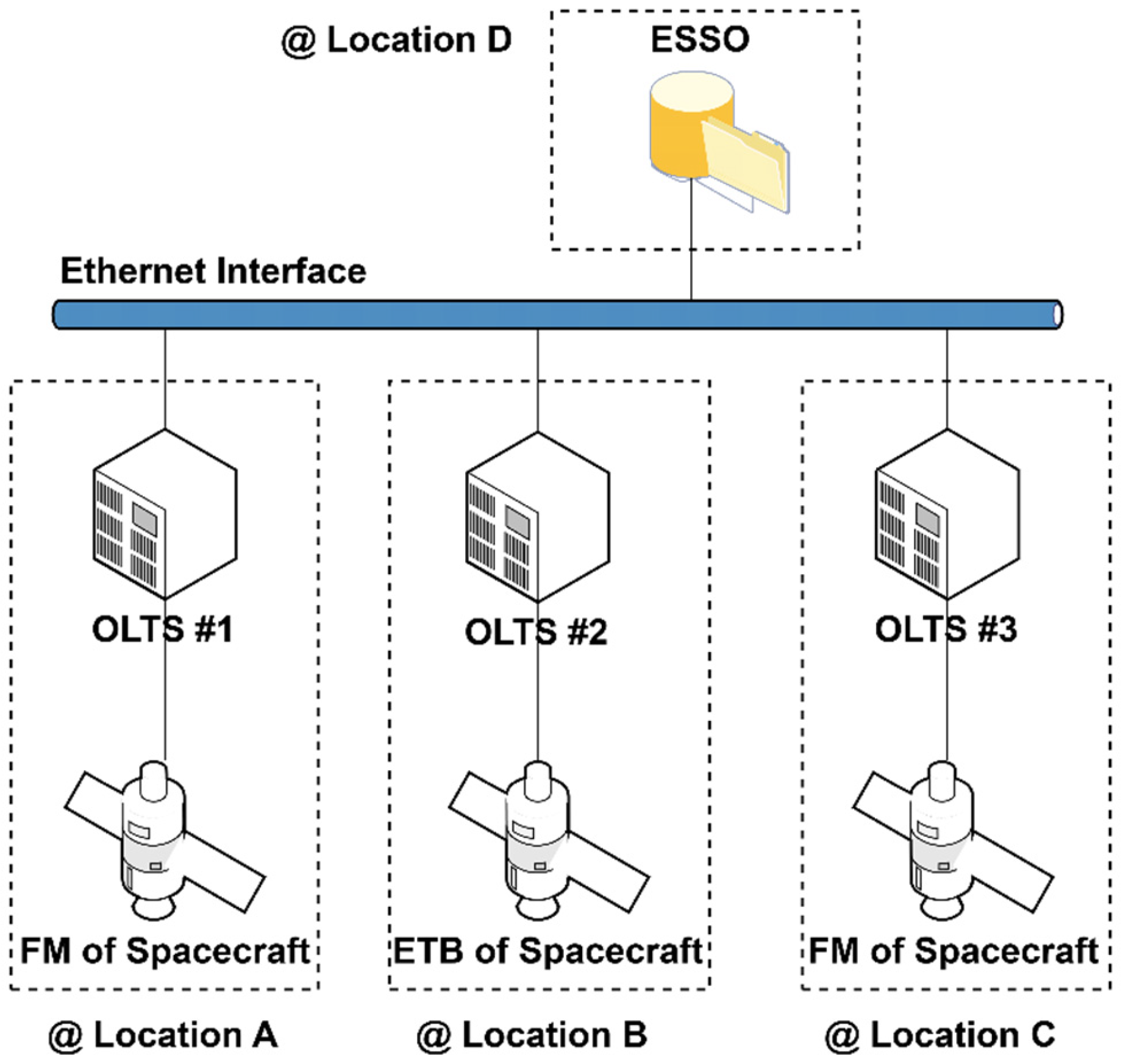
The OLTS is composed of three independent systems, which are each designed to address specific operational requirements. One key capability is its ability to conduct multiple tests concurrently, for example, on several spacecraft or on both the FM and ETB configurations. In particular, the test system is designed for use in both phases and can therefore be employed during the EM stage. Notably, even at this stage, the units provide the same electrical functions and interfaces as the FM units; the only distinction is that they have not undergone physical qualification through environmental testing. This consistency is critical, as it ensures the reliability and comparability of test results from the ETB phase through to subsequent FM testing. Also, environmental tests such as Electromagnetic Compatibility (EMC), vibration, and Thermal Vacuum Chamber (TVAC) testing are carried out at different facilities, and each system is equipped with wheels at the base to provide mobility. This implies that when these three units operate simultaneously and in remote locations, the processes of data collection and distribution become increasingly complex and pose additional challenges. Notably, information regarding the MGSE components or the facility-provided TVAC pressure and temperature is not included as input to the test system, as these parameters are not directly related to the spacecraft bus or payload. Instead, the test system conducts functional tests both before and after environmental tests, including vibration, shock, and TVAC testing. In addition, during certain environmental tests, the test system continuously performs functional tests to verify the onboard unit. The results of these successive functional tests provide valuable data for trend analysis and for detailed examination in the event that anomalies occur. To address this, the system transmits data to the ESSO using the Test Data Transfer (TDT) over an Ethernet interface. The centralized storage server dedicated exclusively to the OLTS provides expandable capacity and supports simultaneous connections with up to three OLTS units. The configuration is illustrated in Figure 2. Payload data from all OLTS units are transmitted to the ESSO through Ethernet, enabling engineers to access the data from any location. They can retrieve test data from the ESSO even if they conducted the ground test at a distant site or at multiple different sites. To ensure data integrity, access permissions are configured to allow copying while preventing unauthorized deletion or modification. The test system is fundamentally not designed for multi-level projects. Instead, it is intended to support multiple ground tests conducted simultaneously in physically separated facilities within KARI site at the system level in accordance with system engineering standards. Although not a lightweight portable system, the test system can be safely relocated by operators. Each rack is equipped with wheels at the base, enabling mobility between ETB laboratories, FM clean rooms, environmental test facilities, and the launch pad.

2.2. Payload Telemetry Categorization and Ground System Implications

2.2.1. Classification of Payload Telemetry

Payload data that the OLTS handles during the test phase can be divided into two categories: science data and engineering data. Science data refer to observation data such as electro-optical (EO) images, synthetic aperture radar (SAR) images, magnetometer sensing data, or data from other instruments. Engineering data consist of housekeeping data and ancillary data. Housekeeping data indicate the health state of payload instruments, while ancillary data contain the necessary information to process the science data. Table 1 presents a hierarchical classification of the payload telemetry discussed previously, which is organized from general categories to specific data content types.

2.2.2. Impact on Ground System Architecture

The OLTS is classified as a type of Electrical Ground Support Equipment (EGSE) specifically designed to support payloads and their associated data communication subsystems. Although it is more closely aligned with payload EGSE as noted in refs. [36,37], its classification can vary depending on mission-specific system architectures. For instance, in Korea’s Geostationary Earth Orbit (GEO) satellite program, the payload data subsystem is treated as part of the bus system. Accordingly, a payload EGSE is categorized as a bus EGSE. In contrast, in Low-Earth Orbit (LEO) satellite programs, a payload data subsystem is typically decoupled from the bus, and a payload EGSE is not included in the bus EGSE configuration, as shown in ref. [38]. Based on this classification standard, the OLTS is categorized as a type of bus EGSE, as its development plan and architecture were initially designed within the framework of a GEO satellite program.
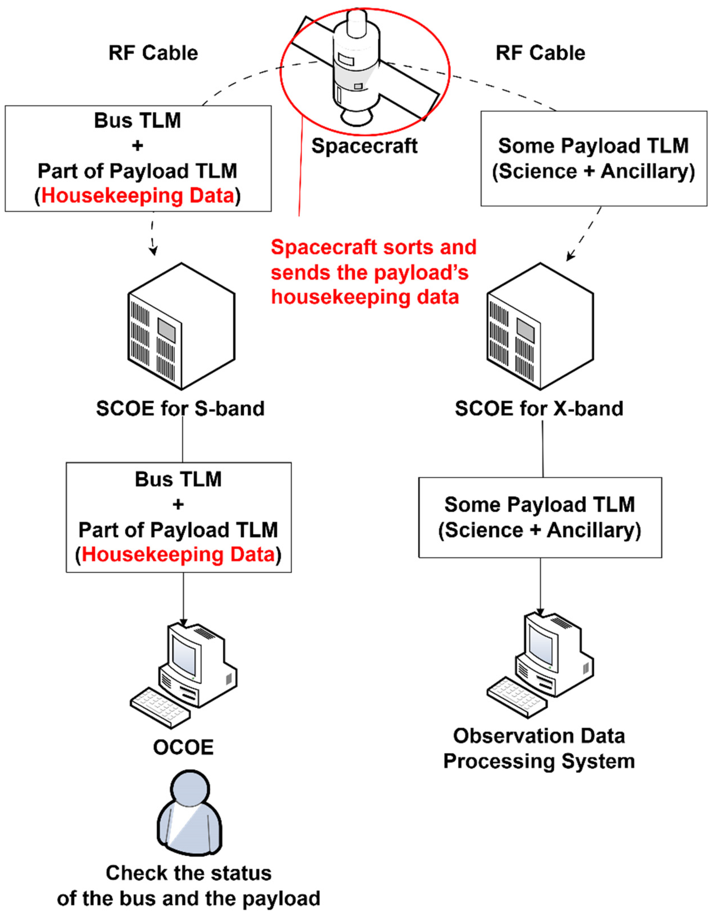
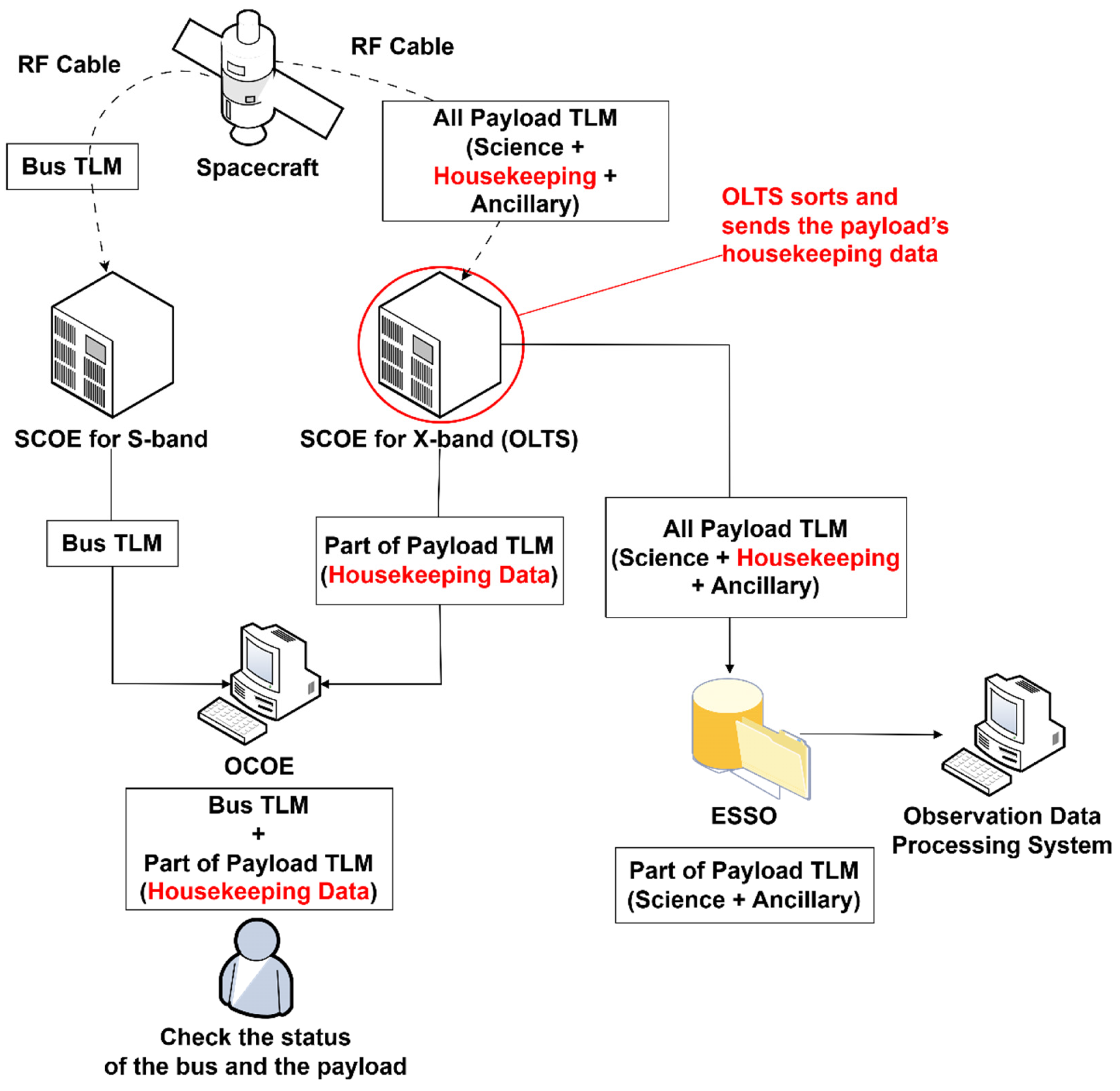
In earlier missions such as COMS, science and housekeeping data were transmitted separately via X-band and S-band, respectively. However, as recent missions generate larger volumes of payload data, all payload information, including science, ancillary, and housekeeping data, is now transmitted via the X-band link, while the S-band is reserved solely for spacecraft bus telemetry. This change in communication design affects the ground test system. In order to utilize the existing ground test infrastructure, the test system receiving payload data through the X-band must now incorporate additional functionality to sort the payload data. The OLTS addresses this requirement by first receiving all types of payload data, regardless of content, and then sorting and forwarding the necessary information to the OCOE or other connected systems. In particular, it sends housekeeping data to the central checkout system so that the status information for both the spacecraft bus and the payload can be collected and displayed in a unified interface. Consequently, the OCOE can present all relevant telemetry seamlessly. The only difference between the two configurations lies in whether the payload data are sorted within the spacecraft or by the OLTS. As shown in Figure 3, earlier systems like COMS did not require ground-based data sorting, since both spacecraft and payload health data were transmitted together via the S-band. In contrast, Figure 4 illustrates the configuration used in the GEO-KOMPSAT series, where the test system receives and parses all payload data before forwarding housekeeping data to the OCOE. Although the OLTS is primarily designed for the latter, it can be adapted to support the former by enabling or disabling its internal data-sorting function. This flexibility allows it to accommodate changes in spacecraft data configurations, enabling the efficient reuse of existing ground systems with minimal modification and contributing to a reduction in overall development costs.

3. Enhanced Data Management for Automated Spacecraft Ground Testing

In recent years, data rates have increased significantly due to advances in technology and the growing number of payloads onboard spacecraft. As a result, the volume of test data has expanded considerably, and the complexity of its distribution and validation has also become greater. Traditionally, payload data generated during ground testing were retrieved directly from the test system using USB drives or portable storage devices. Test operators were required to wait until the test was complete before connecting the storage device to transfer the data. Aside from the time consumed by the test itself, the copying and distribution of large test data introduced substantial operational delays. To improve the efficiency of ground testing, a new approach to test data management is essential.

3.1. Test Data Transfer for Centralized Test Data Storage

3.1.1. Limitations of Manual Transfer in Legacy Systems

The trend toward large volumes of data has influenced not only spacecraft operations but also the testing process. In other words, the design and development of ground test systems places significant emphasis on test data management. The OLTS is developed as the first system in Korea’s space program to address test data management and automation with the goal of enhancing the efficiency of ground testing. In general, test automation refers to the use of scripts using standardized languages such as Procedure Language for Users in Test and Operations (PLUTO) by ECSS, the Spacecraft Test and Operations Language (STOL) by NASA, and the European Test Operation Language (ETOL) by ESA [1,34,39,40,41]. It automatically conducts subsystem tests, including the Electrical Power Subsystem (EPS), Telemetry, Telecommand, and Ranging (TCnR), and the Attitude and Orbit Control Subsystem (AOCS). In contrast, test data transfer automation in test systems refers to the automatic centralization of test data and is distinct from script-driven test procedure automation. In previous programs, data were manually transferred by engineers following the completion of tests, requiring additional time even after testing had concluded. USB drives or portable storage devices were typically used, and engineers were required to physically access the test system to retrieve data. Even with smaller data sizes, the manual process of copying and distributing files proved time consuming. As modern programs increasingly demand more efficient ground-testing operations, the automation of this process has become essential.

3.1.2. Design Principles for Automated File Transfer

To address the inefficiencies in test data transfer, two approaches have been considered: a hardware-based solution and a software-based solution. Replacing the existing system with higher-performance hardware falls under the first approach. Since the speed of data transfer is inherently limited by hardware capacity, this strategy can offer some improvement. However, as data rates and volumes continue to increase, hardware upgrades become less practical and cost-effective. Therefore, greater attention has shifted to software-based solutions, such as data management automation.
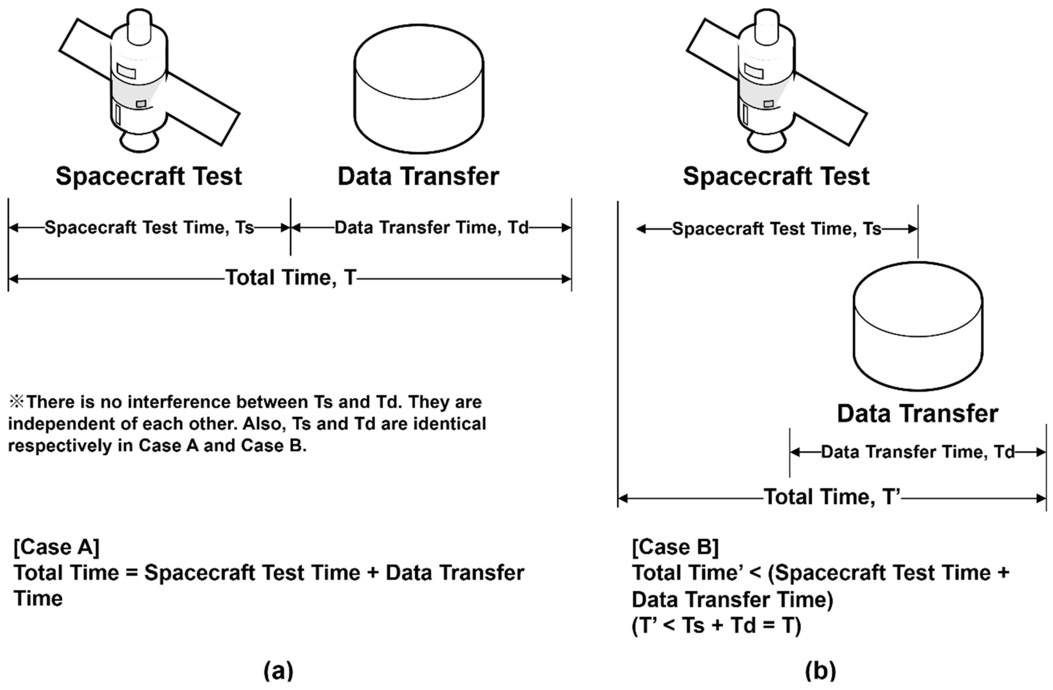
From a software perspective, two primary issues are observed in legacy systems. First, data transfer typically begins only after the test is complete. However, if data transfer begins during the test rather than after its completion, the overall processing time can be significantly reduced. Figure 5 illustrates this point. In Case A, shown in Figure 5a, representing the previous architecture, data transfer starts only after the test ends, resulting in total time T = Ts + Td, where Ts is the spacecraft test time and Td is the data transfer time. In Case B, shown in Figure 5b, a more efficient configuration allows parts of Ts and Td to overlap, enabling data transfer to begin during the test. As a result, the total time T′ in Case B is always less than or equal to T. This overlapping is made possible by changing the event trigger for transfer from “completion of a test” to “completion of a test file.” The second issue in legacy systems was the need for engineers to remain on standby until the data transfer finished. While the test itself requires operator supervision, the transfer process does not. If this task is automated, engineers can be relieved of this burden, especially during long-duration tests such as TVAC or burn-in tests, which may run continuously for several days. Automatic transfer without manual intervention significantly reduces processing time and operator workload, thereby improving overall test efficiency.

3.1.3. Transfer Automation Based on Prefix Algorithm

To enable the early transfer, it is necessary to understand how the OLTS generates test files. Large volumes of data are stored internally, and the number of files depends on the test duration. Typically, more than a dozen test files are generated per hour. After a certain period from the start of the test, most files are in a closed state with only a few remaining in an open state during the test. All files ultimately transition to a closed state upon test completion. According to the OLTS’s test file closure rule, a file transitions from an open to a closed state under two conditions: first, when the size of an ongoing test file reaches the user-defined maximum size (typically set to 4 GB per file); and second, when the test concludes. If the test continues after the initial condition is satisfied, a new file is opened. Test files are generated in sequence rather than simultaneously, and this process continues until the test is completed. During testing, files that reach the maximum size can be regarded as complete, whereas smaller files may still be in progress. However, smaller files may also be complete if the test has ended. Therefore, file size cannot be used as a definitive indicator of file state.
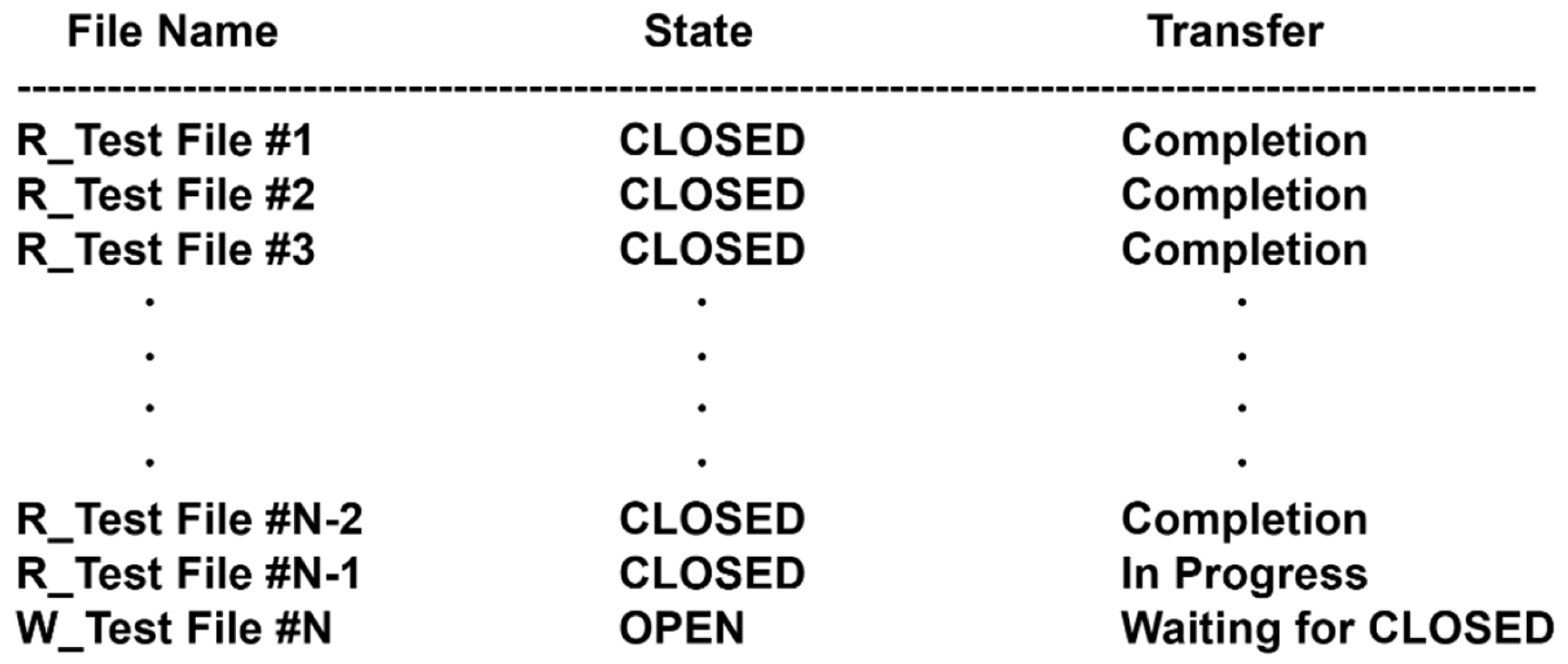
To clearly distinguish the state of each file, the OLTS employs a prefix-based naming algorithm. The system modem inserts a capital letter at the beginning of the file name: “W_” denotes a file still being written (open state), while “R_” indicates a completed file (closed state). These prefixes intuitively represent “write” and “read.” This rule is essential for automation, allowing the system to identify closed files and transfer them efficiently. The TDT software in the OLTS is designed to detect files with the prefix “R_” and transfer them immediately. This process does not require the test to finish and operates without manual input. In this way, the OLTS enables the automation of test file transfers. Figure 6 illustrates the file state during creation and transfer.
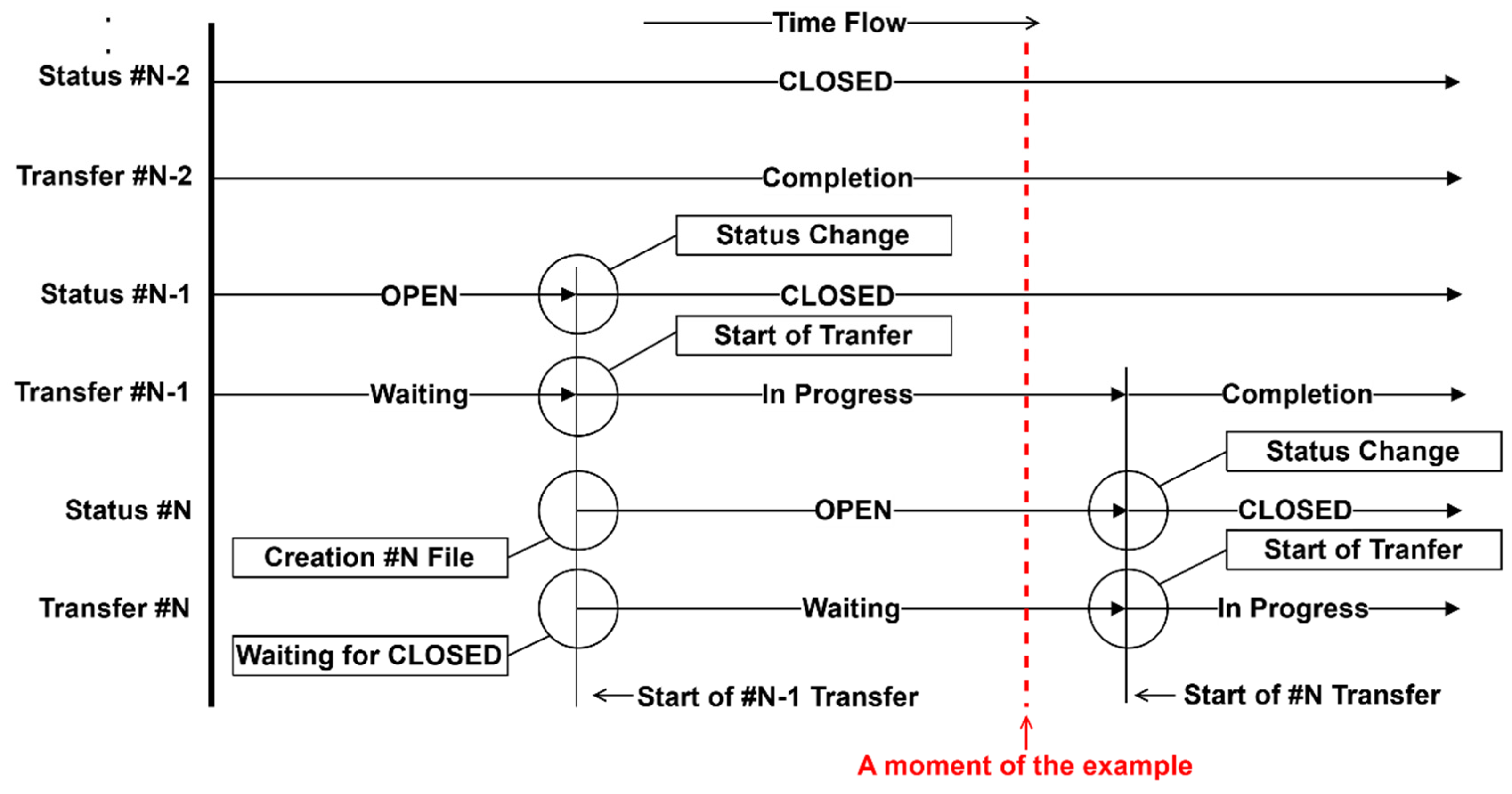
All test files are in a closed state except for the final file, #N, which remains open and thus not ready for transfer. The #N-1 file is closed but still in the process of being transferred. The other closed files have already been transferred successfully. The prefix ‘W_’ on the #N file indicates its open state. When the prefix changes to ‘R_’, TDT recognizes the file as closed and begins the transfer. This sequence is shown in Figure 7. The dashed line represents the timing of Figure 6, while solid lines show the initiation of transfer for the #N-1 file and the creation of the #N file. Each time a file changes from open to closed, two events occur: the closed file is transferred, and the next file is created. This sequence continues until the test concludes. Through this automated process, the OLTS minimizes manual actions and reduces the overall test time, particularly in long-duration or resource-intensive test campaigns.

3.2. Space Packet Extractor for Post-Processing and Data Validation

Various research groups or subsystem teams often request different types of test data depending on their mission responsibilities. For instance, researchers responsible for payloads typically request data in the form of Space Packets (SPs), as observational data are generated in this format. Similarly, engineers managing the interface between the onboard data processor and modulator require test data formatted as Channel Access Data Units (CADUs). However, the raw data produced by the OLTS do not consist of clean CADUs; they contain additional information that is appended during ground testing. To meet diverse requirements for SPs, CADUs, or other formats, a dedicated post-processing tool is necessary. The Space Packet Extractor (SPE) is developed and installed within the ESSO system to support this need. By offloading the post-processing tasks from the OLTS to the ESSO, it allows the test system to focus exclusively on test execution and data transmission, thereby minimizing the risk of system overload or delay. Although the name of the SPE mentions only SPs, it is capable of handling multiple data types that conform to the Consultative Committee for Space Data Systems (CCSDS) 133.0-B-2 [42] and 732.0-B-4 [43] standards. In addition, the SPE is designed to perform both format conversion and data validation in an automated fashion. All processing steps operate based on predefined settings, eliminating the need for operator intervention.

3.2.1. Input and Output Data Overview

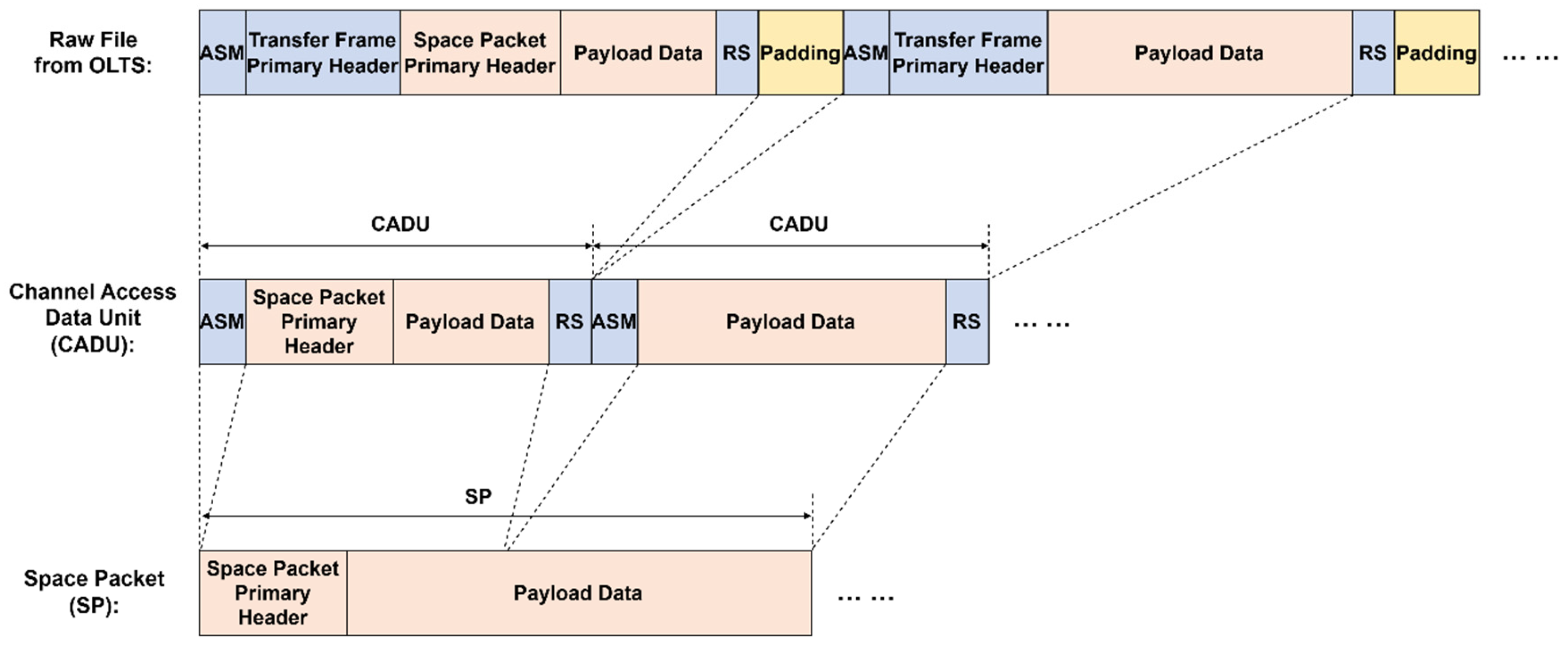
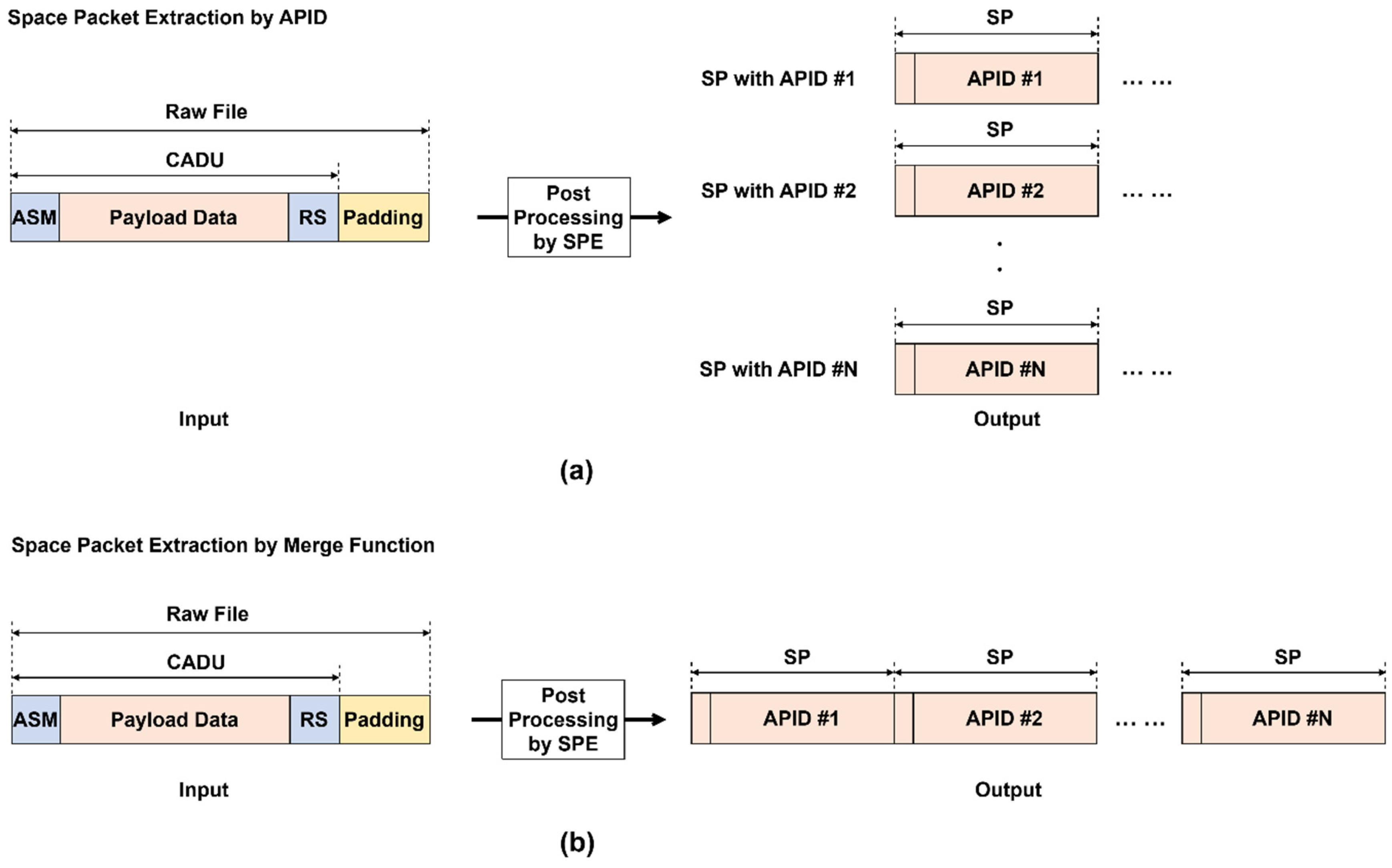
The input data for the SPE consist of raw files received from the OLTS via TDT processing. These raw files contain CADU information along with additional metadata and are processed before subsequent data handling begins. Regarding the output, the SPE creates two types of processed data: CADU and SP files. In the context of CADU extraction, the SPE supports two options. Option 1 produces one CADU file for each input raw file, maintaining a one-to-one correspondence. Option 2, referred to as the merge function, combines multiple raw files into a single CADU file, removing all additional padding and reconstructing a continuous CADU stream. For SP data, two extraction options are also available. Option 3 entails sorting by an Application Process Identifier (APID), where the SPE generates one SP file for each APID. In this case, even a single raw file may produce multiple SP files if it includes data from multiple APIDs. In contrast, the merge function, Option 4, consolidates SP data from single or multiple raw files into a comprehensive file. This merged file preserves the chronological sequence of packet processing and may contain SPs with either a single APID or multiple APIDs. The internal structures of the raw file, CADUs, and SPs are illustrated in Figure 8. For clarity, certain internal fields, such as the Multiplexer Protocol Data Unit (M_PDU), are omitted.

3.2.2. CADU Extraction Options

During CADU extraction, the SPE removes padding data that are inserted during the OLTS data collection process. With Option 1, each raw file is processed individually to generate a separate CADU file. For example, two raw files will result in two CADU files after padding removal. This one-to-one mapping is useful for segment-level verification. Option 2, the merge function, combines multiple raw files into a single CADU file, eliminating padding in the process. This is especially helpful for debugging or direct comparison with onboard spacecraft data. Onboard CADU streams are continuous and unpadded, and they may exceed 4 GB in size. In contrast, OLTS-generated raw files are segmented (each limited to 4 GB) and padded due to data splitting on the receiver side. Merging restores data continuity and comparability.

3.2.3. Space Packet Extraction Options

For SP extraction, the SPE offers two additional options: APID-based sorting and merging. Option 3 sorts SPs by their APID values. If a raw file includes multiple APIDs, the SPE creates a separate output file for each APID. This results in a “single-input, multiple-output” scenario. Even if only one raw file is used, multiple SP files can be generated based on the APIDs contained within. Figure 9a depicts this case, where each output SP file is labeled with its respective APID. When a raw file contains only a single APID, only one SP file is generated. Option 4 is a merge function that consolidates SPs from one or more raw files into a single output file. This merged file contains SPs corresponding to various APIDs and preserves the temporal sequence in which the SPE processes them. This is useful for verifying time-synchronized data with onboard spacecraft records. Figure 9b illustrates this process, which applies regardless of the number of input raw files.

3.2.4. Post-Processing Validation and Monitoring

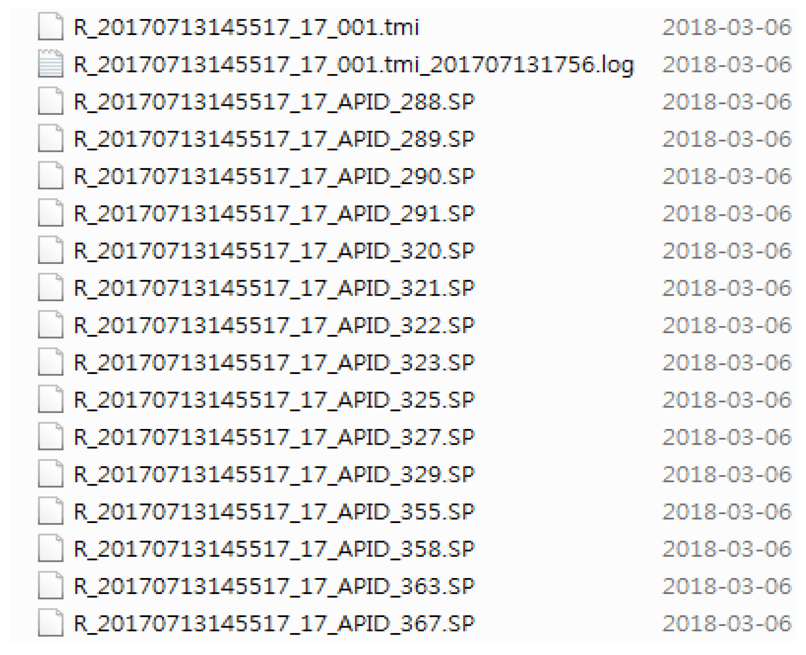
The SPE validates test data by examining key telemetry fields, such as the Space Packet Sequence (SPS) count and the Virtual Channel Data Unit (VCDU) count. When the test proceeds without error, these counters increase sequentially without omission. Additionally, the Reed–Solomon (RS) field is used to verify the integrity of each transmission. Although RS checks are typically performed by the OLTS receiver, the SPE has the capability to repeat this verification during post-processing if necessary. All operations, including format transformation and data validation, are fully automated. Much like the TDT system, the SPE utilizes a prefix algorithm to monitor designated directories for test files. Files with the prefix “R_” are interpreted as closed and are automatically selected for processing. The SPE also checks for remaining files with the prefix “W_”. To operate correctly, all configurations, such as watch folder paths and processing parameters, must be predefined. Once initialized, the SPE can begin processing within minutes of test execution, even while the test is still ongoing. The results of this process are illustrated in Figure 10, where the .TMI file represents the raw input from the OLTS and the input to the SPE, while the .SP files represent the resulting outputs. The .log file contains metadata such as processing timestamps, file sizes, validation summaries, and configuration details. Each .SP file corresponds to a specific APID, confirming that the APID-based sorting was performed correctly.

4. Implementation and Results Analysis

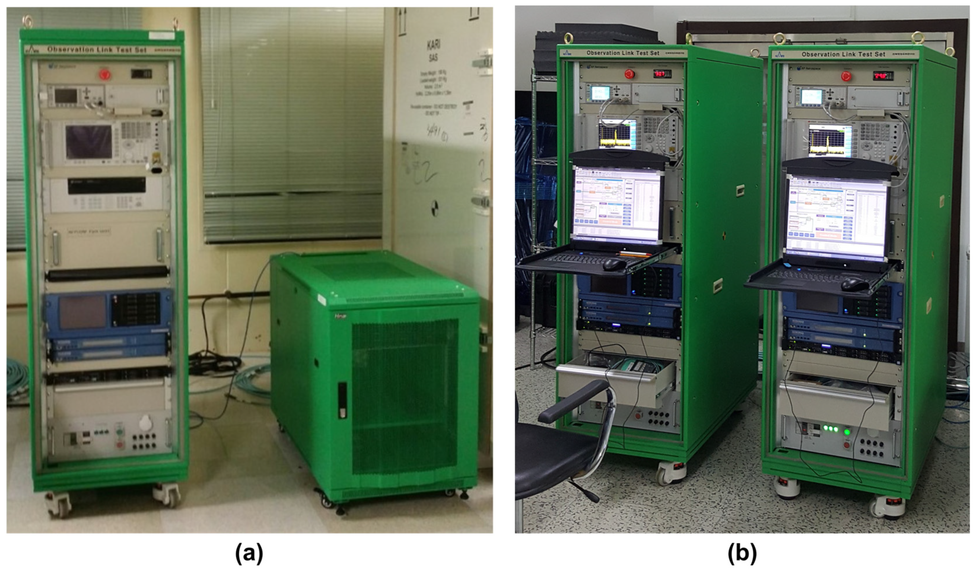
The test data management strategy described earlier is aimed at reducing testing time and improving efficiency. Once the spacecraft ground test begins, processes such as test data backup, post-processing, and validation are executed automatically. The ground test generates a substantial volume of test data in real time, and the TDT identifies the state of the test data and transmits it to the ESSO in real time. Subsequently, the SPE installed on the server detects incoming test files and begins processing and validating them based on predefined rules. To support such a test system architecture, it includes two primary hardware subsystems: the OLTS, which handles ground testing and payload data receptions, and the ESSO, which has large capacity storage and automated post-processing. Table 2 summarizes the specifications of each subsystem, including CPU, storage capacity, operating system, and Ethernet interface. Figure 11 shows the rack-mounted configuration of OLTS and ESSO systems, which was designed for spacecraft ground testing and interconnected via a 1 Gbps Ethernet interface. Specifically, Figure 11a presents the physical setup of OLTS and ESSO systems, while Figure 11b shows two OLTS units in operation during a self-validation ground test. This setup enables seamless data flow and automation during the test campaign. This section applies the proposed data management strategy to a practical spacecraft test to demonstrate the effectiveness of the test system.

4.1. Analysis of TDT Processing Logs

4.1.1. Data Filtering and Preprocessing

To assess the effectiveness of the test system, it was applied to actual satellite testing. All test data generated by spacecraft payloads or the transmission subsystem were automatically delivered to the ESSO without any user intervention. This automation produced not only a large volume of data but also execution logs that record detailed timestamps for all events. To ensure the reliability of the analysis, approximately one year of log data was collected. Due to the vast amount of log data, big data analysis techniques were used. Each test generated a different number of test files depending on factors such as test type, purpose, duration, and conditions. For consistency, tests that generated fewer than 10 data points were excluded due to insufficient sample size. Furthermore, the last file in each transfer log was also excluded, as explained in Section 3. When a file reaches 4 GB, it is automatically closed and transferred. Therefore, all files, except the last one, are typically 4 GB in size. By excluding the final file, the analysis focuses only on test files of uniform size, resulting in one fewer analyzed file per test than the number generated.

4.1.2. Statistical Analysis of Phase 1

The analysis of TDT logs during Phase 1, covering the period from 29 June 2016 to 8 February 2017, is presented in Figure 12. A total of 7998 test files were transferred, and no transmission failures were reported throughout the entire period. All dates shown in the figure indicate the start date of each test, and the numbers in parentheses represent the total number of files transferred during each test. For example, the test conducted on 16 January 2017 lasted five days and resulted in the transfer of 1359 files, while the test that began on 31 January 2017 also spanned five days and produced 1190 files. These long-duration tests were designed to verify the reliability of subsystems or units, and accordingly, they generated the largest volumes of data, as reflected in Figure 12c,d. In terms of transmission time, most files were transferred within a range of 30–80 s, as illustrated in Figure 12a, with one exception: a single file required 96 s to transmit on 25 November 2016. It is the 55th out of 99 transmitted test files and suspected to have experienced delayed data generation or temporary network instability. Figure 12b provides an overlapping histogram of all transmission times, where the majority of events are clustered between 35 and 40 s. However, due to the overlap, it is difficult to identify which specific tests contributed most to this range. This ambiguity is resolved in Figure 12c,d, which indicate that the peak observed in Figure 12b was primarily driven by the two aforementioned long-duration tests. Notably, transmissions with durations shorter than 40 s became increasingly frequent after 14 November 2016. This trend is corroborated by the distributions in Figure 12a,c, both of which show relatively low peak counts and broader transmission time distributions prior to that date.
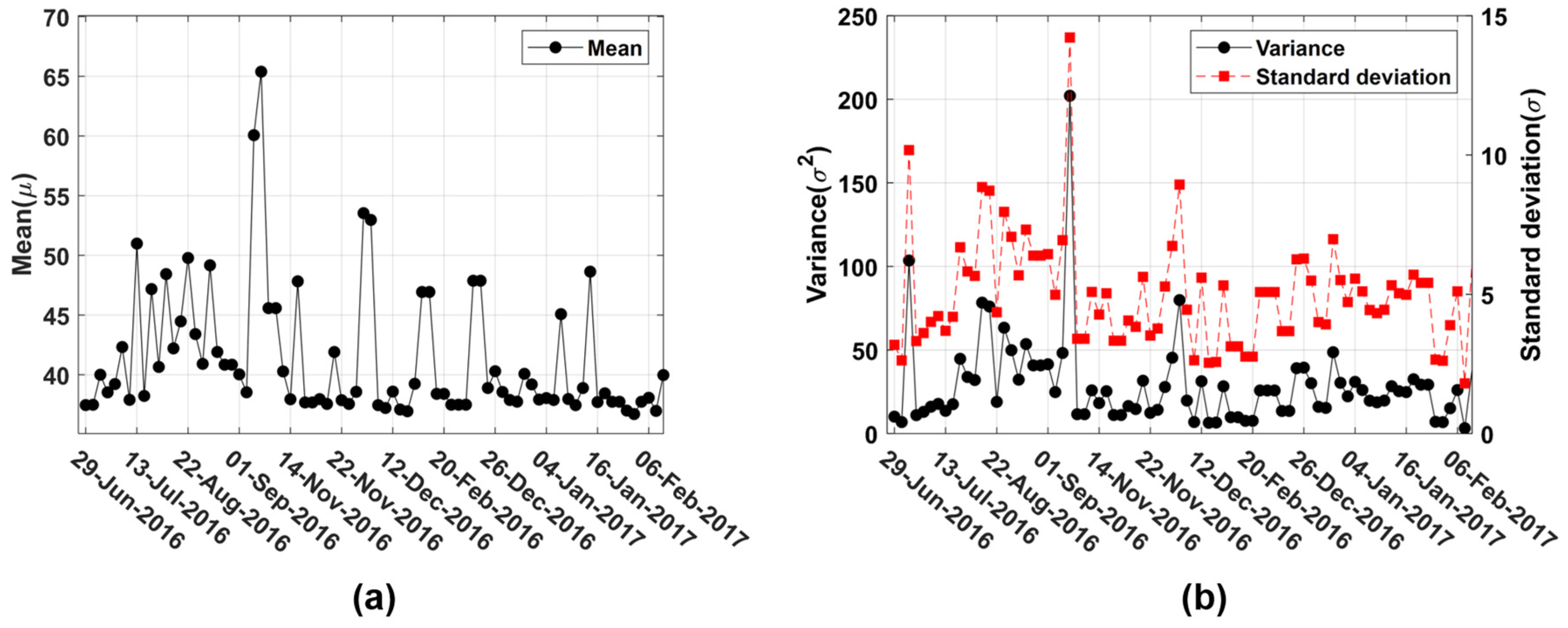
The statistical distribution of transmission times during Phase 1 is further analyzed in Figure 13. As shown in Figure 13a, the highest mean transfer time, 65 s, was recorded on 30 September 2016. The corresponding variance and standard deviation, as displayed in Figure 13b, were also the highest, with values of 202 and 14, respectively. Notably, only 74 files were transmitted during that test, which may explain the greater variability in timing. In general, a higher number of transferred files tends to result in lower variability of the transfer time distribution. For instance, four tests involved transferring more than 200 files, specifically 209, 1359, 397, and 1190. Although they were conducted on different dates, these tests exhibited similar mean transfer times due to sufficient sample numbers, as summarized in Table 3. Furthermore, it is worth noting that not only these four major tests but also most tests in Figure 13a show mean transmission times below 40 s, suggesting that the overall mean is likely to fall within this range. It is confirmed by the calculated mean transmission time across all 7998 transfers during Phase 1, which is 39.7743 s.

4.1.3. Statistical Analysis of Phase 2

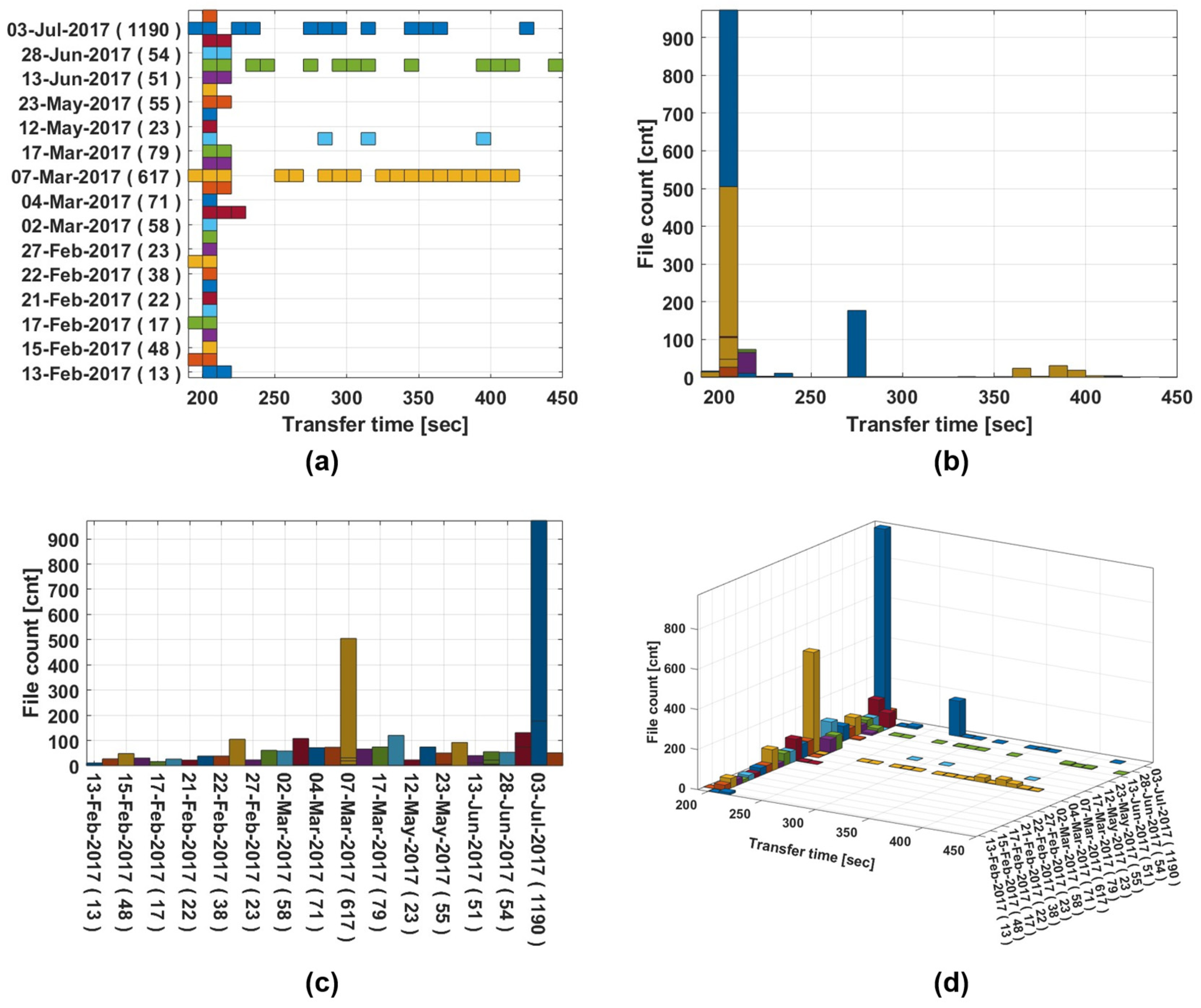
During Phase 2, the ESSO was relocated to a different test room, resulting in noticeable changes in transfer times due to the altered network environment. A total of 3571 transmissions, recorded between 13 February and 31 August 2017, were analyzed with no transmission failures observed. As shown in Figure 14a, transfer times were generally distributed within a narrow range with four notable deviations occurring in the mid- and late-phase periods. In Figure 14b, most transfer times are clustered around 200 s, although certain anomalies were observed, specifically, more than 150 transmissions on 3 July 2017 peaked near 270 s, and several on 7 March 2017 approached 370 s. Figure 14c presents the number of transferred files per test date. However, overlapping data points make it difficult to discern counts beyond the highest value for each date. On 7 March and 3 July 2017, the number of transferred files reached peak values of 505 and 973, respectively. Figure 14d provides a combined view of the distribution of transfer times and file counts by date.
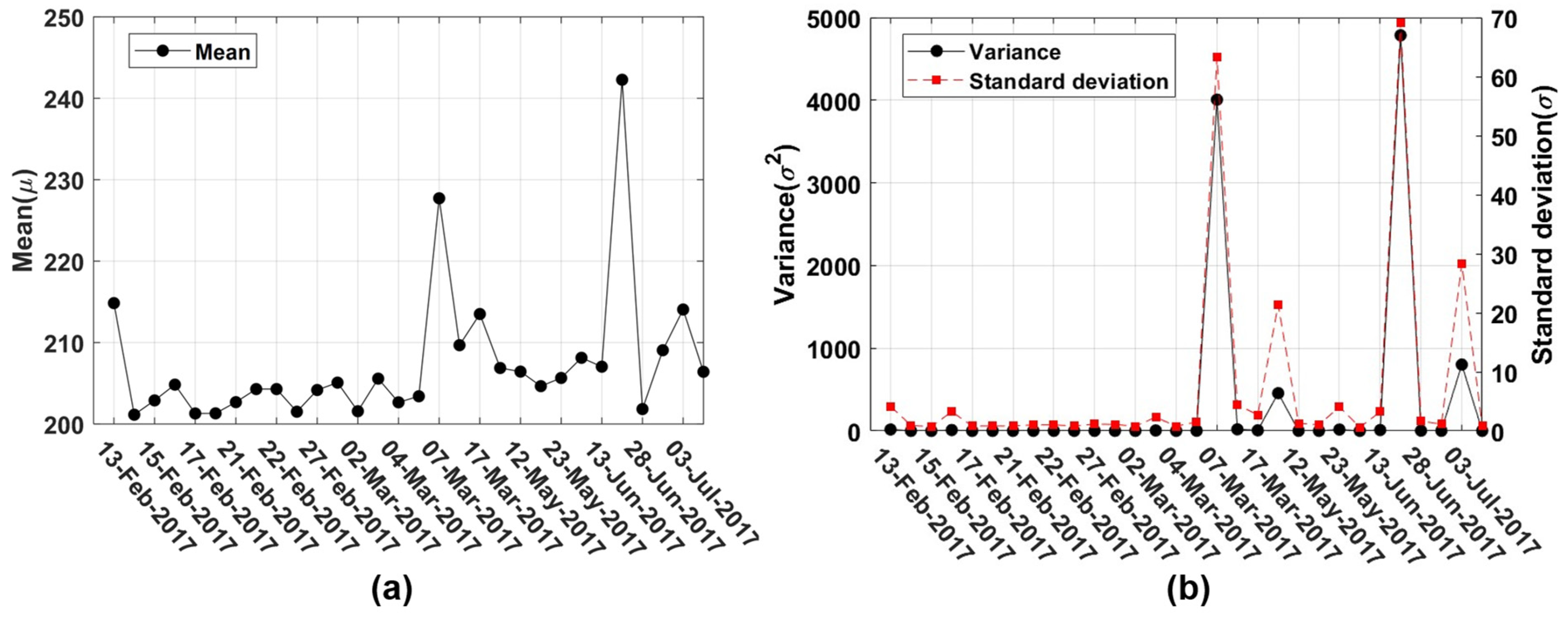
Figure 15 presents the mean, variance, and standard deviation of transmission times during Phase 2. Although the spacecraft and test equipment remained stationary at the same physical locations throughout both Phase 1 and Phase 2, the mean transfer times during Phase 2 exceeded 200 s. This trend is attributed to the relocation of the ESSO. As shown in Figure 15a, the highest and second-highest mean transfer times were recorded on 20 June and 7 March 2017 with values of 242 s and 227 s, respectively. The former test involved 617 test file transfers and exhibited a wide time distribution, accounting for the elevated mean. The latter test had 99 test file transfers and also showed substantial variability. This variability is further reflected in the high variance and standard deviation illustrated in Figure 15b. Despite the wide distributions, the remaining tests in Phase 2 exhibited mean transfer times below 215 s. Consistent with this observation, the mean transfer time for all 3571 transmissions in Phase 2 was calculated to be 213.3475 s.

4.2. Analysis of SPE Processing Logs

4.2.1. Setup and Log Collection

SPE processing was analyzed using logs from 25 September 2017 to 23 March 2018. All tasks were conducted according to predefined rules and were completed without errors. Unlike the TDT process, SPE processing occurs exclusively within the ESSO and is unaffected by network or location changes.

4.2.2. Analysis of Processing Time Variation

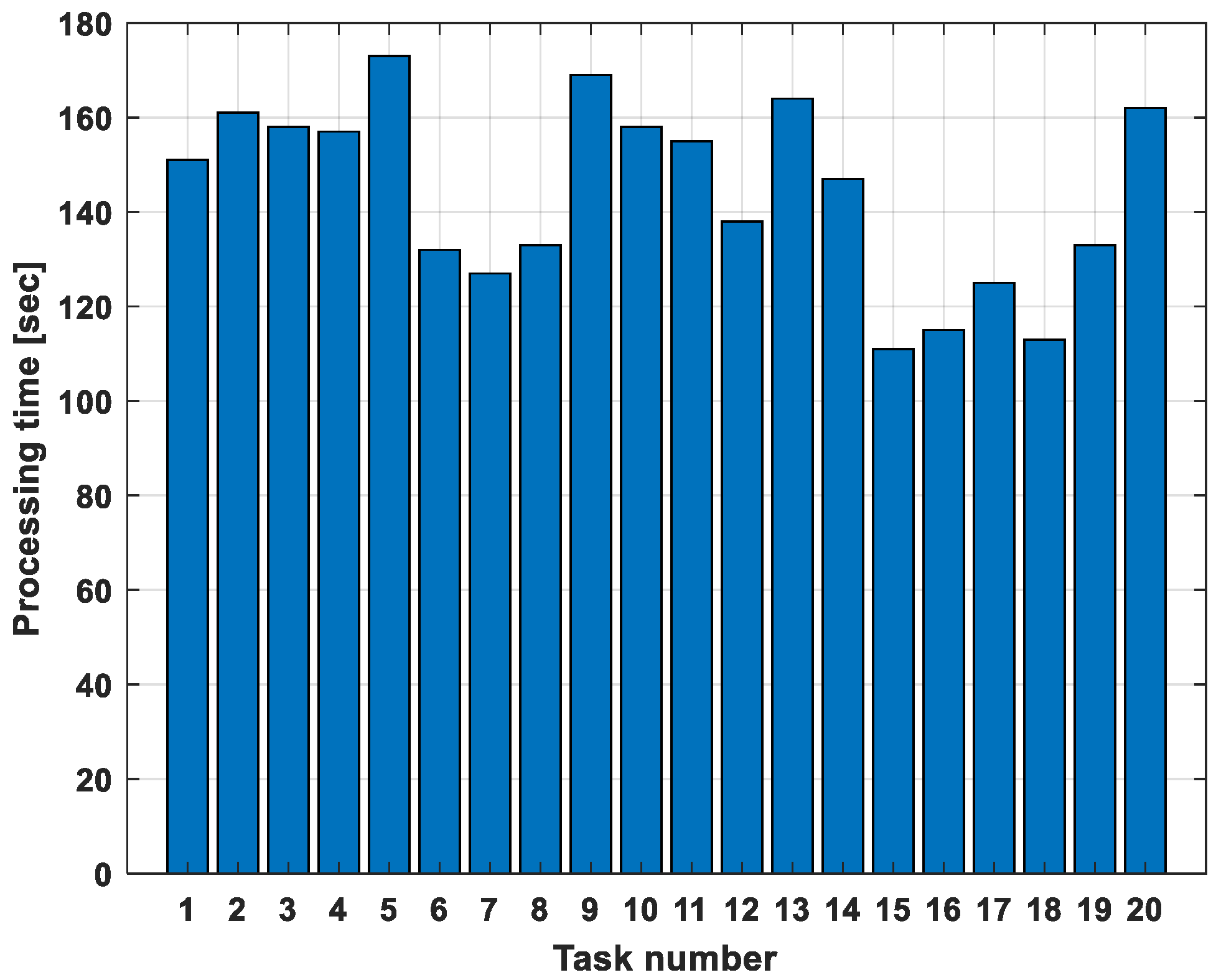
To compare automated processing durations, tasks using the same rules and identically sized files were selected. Table 4 presents rule and file size information, and Figure 16 illustrates the processing times for 20 such tasks.
Despite uniform size and rules, processing times varied due to differences in processor load and file composition. ESSO is linked via LAN to the test system, allowing simultaneous TDT reception and SPE processing. ESSO may receive test files from up to three OLTSs simultaneously, so the processor load varies with test conditions. However, since the SPE logs do not record processor load data, a correlation analysis is not possible. Moreover, files of identical size can vary in packet composition. For instance, one 4 GB file might include two APID types with thousands of packets, while another may contain many APIDs and tens of thousands of packets. These differences contribute to the variability in processing time. Under these conditions, the average processing time for a 4 GB test file is calculated as 144 s. The precise impact of processor load and packet composition remains an open research topic.
To evaluate the expected whole processing time for a standard test file, a representative file size of 4 GB was considered, which was used consistently across both test phases. Table 5 provides a comparative summary of the overall processing durations measured during Phase 1 and Phase 2. The total time reported in Table 5 represents the sum of the TDT and SPE durations. In Phase 1, the TDT detects and transmits a file from the OLTS to the ESSO in approximately 40 s, whereas in Phase 2, the same operation takes about 213 s. The SPE then performs automated post-processing, requiring approximately 144 s in both phases. The change in ESSO location affects only the TDT timing, while the SPE duration remains constant. As the spacecraft and test equipment remained at the same location throughout the entire testing period, the differences in total processing time are attributed solely to the ESSO relocation, allowing for a clear estimation of end-to-end system performance.

5. Conclusions

With recent trends in space development, the effective management of large volumes of test data generated by high-rate and complex systems has become increasingly important. Given that efficiency during ground testing is directly linked to the duration of test and verification processes, there is growing interest in data management from a cost-reduction perspective.
In this study, enhanced test data management and test systems were successfully developed and implemented in actual space programs. The TDT process enables the transfer of test files to begin during ongoing testing, rather than waiting for test completion, as soon as closed test files are detected. The SPE then provides multiple test data formats and performs data validation with the transferred test data. Furthermore, the automation of TDT and SPE operations is realized through prefix-based algorithms, which significantly enhance testing efficiency, particularly in long-duration tests such as burn-in or TVAC tests. To quantitatively evaluate the enhancement in test efficiency, the transmission times of TDT were analyzed based on approximately one year of processing logs from actual spacecraft testing. The analysis demonstrated that the system exhibited robust performance with average transfer times of approximately 40 s. and 213 s per 4 GB file in Phase 1 and Phase 2, respectively. Although the analysis shows that the location of the ESSO affects transfer time, all test data were successfully transferred in both phases. For SPE processing, test cases conducted under identical conditions were categorized, and the mean processing time was calculated to be approximately 144 s per 4 GB file for evaluation.
Although the test data analyzed in this study were collected from certain GEO satellite programs conducted in the late 2010s, the underlying principles of the data management strategy remain applicable to a wide range of future missions, including LEO and deep space exploration. This approach offers practical advantages in time and cost efficiency, especially for long-duration missions requiring continuous system-level monitoring and testing. Additionally, the collaborative expansion of storage capacity across ground testing and operational branches represents a promising strategy for future development. While the current strategy has demonstrated reliable performance in actual spacecraft programs, further enhancements may be explored to overcome potential challenges such as network dependency and scalability, especially in simultaneous multi-satellite testing environments. Moreover, another important direction for future work is a thorough performance comparison of the current OLTS once a comparable system becomes available. Such comparisons will not only further validate and broaden the practical applicability of the approach but also provide valuable insights for designing and developing more advanced versions of the OLTS.

Author Contributions

Conceptualization, J.P. and Y.-J.S.; Writing—original draft preparation, J.P.; Writing—review and editing, J.P., Y.-J.S. and D.L.; Supervision, Y.-J.S. and D.L.; Visualization, J.P., Y.-J.S. and D.L.; Methodology, J.P. and Y.-J.S.; Software, J.P.; Data curation, J.P.; Project administration, Y.-J.S. All authors have read and agreed to the published version of the manuscript.

Funding

This research received no external funding.

Data Availability Statement

The data presented in this study may be available on request from the corresponding author. However, due to security and confidentiality considerations, access to the data may be restricted and will be subject to internal review and public release approval by the Korea Aerospace Research Institute (KARI).

Acknowledgments

Young-Joo Song initiated this work while affiliated with the Korea Aerospace Research Institute. The subsequent work and completion of the manuscript were carried out at Kyung Hee University. The authors gratefully acknowledge Jae-Wook Kwon of KARI for his insightful discussions on data security considerations during the preparation of this manuscript.

Conflicts of Interest

The authors declare that there are no conflicts of interest regarding the publication of this paper.

References

  1. Wang, G.; Cui, Y.; Wang, S.; Meng, X. Design and performance test of spacecraft test and operation software. Acta Astronaut. 2011, 68, 1774–1781. [Google Scholar] [CrossRef]
  2. Zhong, P.; Wang, L.; Zhang, G.; Li, X.; Xu, J.; Sun, Q.; Wang, S.; Zhang, S.; Wang, C.; Chen, L.; et al. Thermal-vacuum regolith environment simulator for drilling tests in lunar polar regions. Acta Astronaut. 2025, 229, 13–26. [Google Scholar] [CrossRef]
  3. Rickmers, P.; Dumont, E.; Krummen, S.; Redondo Gutierrez, J.L.; Bussler, L.; Kottmeier, S.; Wübbels, G.; Martens, H.; Woicke, S.; Sagliano, M.; et al. The CALLISTO and ReFEx flight experiments at DLR-Challenges and opportunities of a wholistic approach. Acta Astronaut. 2024, 225, 417–433. [Google Scholar] [CrossRef]
  4. Lal, B.; Sylak-Glassman, E.J.; Mineiro, M.C.; Gupta, N.; Pratt, L.M.; Azari, A.R. Global Trends in Space Volume 2: Trends by Subsector and Factors that Could Disrupt Them. IDA Sci. Technol. Policy Inst. 2015, 2, 5242. [Google Scholar]
  5. Mason, L.S.; Oleson, S.R. Spacecraft impacts with advanced power and electric propulsion. In Proceedings of the 2000 IEEE Aerospace Conference. Proceedings (Cat. No. 00TH8484), Big Sky, MT, USA, 18–25 March 2000; pp. 29–38. [Google Scholar]
  6. Park, J.; Chae, D.; Bang, S.; Yu, M.; Moon, G. The Umbilical Test Set for Successful AIT and Launch Pad Operation. In Proceedings of the 14th International Conference on Space Operations, Daejeon, Republic of Korea, 16–20 May 2016; p. 2324. [Google Scholar]
  7. Kim, G.-N.; Park, S.-Y.; Seong, S.; Lee, J.; Choi, S.; Kim, Y.-E.; Ryu, H.-G.; Lee, S.; Choi, J.-Y.; Han, S.-K. The VISION–Concept of laser crosslink systems using nanosatellites in formation flying. Acta Astronaut. 2023, 211, 877–897. [Google Scholar] [CrossRef]
  8. Pu, W.; Yan, R.; Guan, Y.; Xiong, C.; Zhu, K.; Zeren, Z.; Liu, D.; Liu, C.; Miao, Y.; Wang, Z. Study on the impact of the potential variation in the CSES satellite platform on Langmuir probe observations. Acta Astronaut. 2025, 230, 104–118. [Google Scholar] [CrossRef]
  9. Kim, J.; Choi, M.; Kim, M.; Lim, H.; Lee, S.; Moon, K.J.; Choi, W.J.; Yoon, J.M.; Kim, S.-K.; Lee, S.H. Monitoring Atmospheric Composition by Geo-Kompsat-2: GOCI-2, AMI and GEMS. In Proceedings of the IGARSS 2018-2018 IEEE International Geoscience and Remote Sensing Symposium, Valencia, Spain, 22–27 July 2018; pp. 7750–7752. [Google Scholar]
  10. Kim, J.; Kim, M.; Choi, M.; Park, Y.; Chung, C.-Y.; Chang, L.; Lee, S.H. Monitoring atmospheric composition by GEO-KOMPSAT-1 and 2: GOCI, MI and GEMS. In Proceedings of the 2016 IEEE International Geoscience and Remote Sensing Symposium (IGARSS), Beijing, China, 10–15 July 2016; pp. 4084–4086. [Google Scholar]
  11. Lee, Y.; Ryu, G.-H. Planning for next generation geostationary satellites (GK-2A) of Korea Meteorological Administration (KMA). In Proceedings of the 8th IPWG and 5th IWSSM Joint Workshop, Bologna, Italy, 3–7 October 2016. [Google Scholar]
  12. Choi, J. The Earth’s surface, meteorology, and climate, GEO-KOMPSAT-2 (Cheollian-2/GK2) program. In South Korea National Report to COSPAR 2020; Committee on Space Research (COSPAR): Paris, France, 2020; pp. 9–20. Available online: https://cosparhq.cnes.fr/assets/uploads/2021/01/South-Korea_2020_compressed.pdf (accessed on 7 September 2025).
  13. Song, Y.-J.; Bae, J.; Hong, S.; Bang, J.; Pohlkamp, K.M.; Fuller, S. KARI and NASA JSC collaborative endeavors for joint Korea Pathfinder Lunar Orbiter flight dynamics operations: Architecture, challenges, successes, and lessons learned. Aerospace 2023, 10, 664. [Google Scholar] [CrossRef]
  14. Song, Y.-J.; Bae, J.; Kim, Y.-R.; Kim, B.-Y. Early phase contingency trajectory design for the failure of the first lunar orbit insertion maneuver: Direct recovery options. J. Astron. Space Sci. 2017, 34, 331–341. [Google Scholar] [CrossRef]
  15. Jeon, M.-J.; Cho, Y.-H.; Kim, E.; Kim, D.-G.; Song, Y.-J.; Hong, S.; Bae, J.; Bang, J.; Yim, J.R.; Kim, D.-K. Korea Pathfinder Lunar Orbiter (KPLO) Operation: From Design to Initial Results. J. Astron. Space Sci. 2024, 41, 43–60. [Google Scholar] [CrossRef]
  16. Wei, G.; Li, X.; Zhang, W.; Tian, Y.; Jiang, S.; Wang, C.; Ma, J. Illumination conditions near the Moon’s south pole: Implication for a concept design of China’s Chang’E−7 lunar polar exploration. Acta Astronaut. 2023, 208, 74–81. [Google Scholar] [CrossRef]
  17. Resurs-P 1, 2, 3 (47KS). Available online: https://space.skyrocket.de/doc_sdat/resurs-p.htm (accessed on 5 September 2025).
  18. Resurs-P 4, 5 (47KS). Available online: https://space.skyrocket.de/doc_sdat/resurs-p4.htm (accessed on 5 September 2025).
  19. Resurs-P (Resurs-Prospective). Available online: https://www.eoportal.org/satellite-missions/resurs-p#eop-quick-facts-section (accessed on 5 September 2025).
  20. Yang, Y.; Hulot, G.; Vigneron, P.; Shen, X.; Zhima, Z.; Zhou, B.; Magnes, W.; Olsen, N.; Tøffner-Clausen, L.; Huang, J.; et al. The CSES global geomagnetic field model (CGGM): An IGRF-type global geomagnetic field model based on data from the China Seismo-Electromagnetic Satellite. Earth Planets Space 2021, 73, 45. [Google Scholar] [CrossRef]
  21. Wang, C.; Jia, Y.; Xue, C.; Lin, Y.; Liu, J.; Fu, X.; Xu, L.; Huang, Y.; Zhao, Y.; Xu, Y.; et al. Scientific objectives and payload configuration of the Chang’E-7 mission. Natl. Sci. Rev. 2024, 11, nwad329. [Google Scholar] [CrossRef] [PubMed]
  22. Zou, Y.; Liu, Y.; Jia, Y. Overview of China’s upcoming Chang’E series and the scientific objectives and payloads for Chang’E 7 mission. In Proceedings of the 51st Annual Lunar and Planetary Science Conference, The Woodlands, TX, USA, 16–20 March 2020; p. 1755. [Google Scholar]
  23. Xu, D.; Zhang, G.; You, Z. On-line pattern discovery in telemetry sequence of micro-satellite. Aerosp. Sci. Technol. 2019, 93, 105223. [Google Scholar] [CrossRef]
  24. Wolfmuller, M.; Dietrich, D.; Sireteanu, E.; Kiemle, S.; Mikusch, E.; Bottcher, M. Data flow and workflow organization—The data management for the TerraSAR-X payload ground segment. IEEE Trans. Geosci. Remote Sens. 2008, 47, 44–50. [Google Scholar] [CrossRef]
  25. Kiemle, S.; Molch, K.; Schropp, S.; Weiland, N.; Mikusch, E. Big data management in Earth observation: The German satellite data archive at the German Aerospace Center. IEEE Geosci. Remote Sens. Mag. 2016, 4, 51–58. [Google Scholar] [CrossRef]
  26. Schreier, G.; Dech, S.; Diedrich, E.; Maass, H.; Mikusch, E. Earth observation data payload ground segments at DLR for GMES. Acta Astronaut. 2008, 63, 146–155. [Google Scholar] [CrossRef]
  27. Kim, J.H. The Public Release System for Scientific Data from Korean Space Explorations. J. Space Technol. Appl. 2023, 3, 373–384. [Google Scholar] [CrossRef]
  28. Kim, J.H. Korea space exploration data archive for scientific researches. In Proceedings of the AAS/Division for Planetary Sciences Meeting Abstracts, London, ON, Canada, 2–7 October 2022; p. 211.208. [Google Scholar]
  29. Silvio, F.; Silvia, M.; Anna, F.; Pavia, P.; Rovatti, M.; Rita, R.; Francesca, S. P/L Data Handling and File Management Solution for Sentinel Expansions High Performances Missions. In Proceedings of the 2023 European Data Handling & Data Processing Conference (EDHPC), Juan-Les-Pins, France, 2–6 October 2023; pp. 1–10. [Google Scholar]
  30. De Giorgi, G.; Legendre, C.; Plonka, R.; Komadina, J.; Hook, R.; Siegle, F.; Caleno, M.; Fernandez, M.M.; Fernandez-Boulanger, V.; Furano, G. CO2M Payload Data Handling Subsystem. In Proceedings of the 2023 European Data Handling & Data Processing Conference (EDHPC), Juan-Les-Pins, France, 2–6 October 2023; pp. 1–4. [Google Scholar]
  31. Anderson, J. High performance missile testing (next generation test systems). In Proceedings of the AUTOTESTCON 2003 IEEE Systems Readiness Technology Conference, Anaheim, CA, USA, 22–25 September 2003; pp. 19–27. [Google Scholar]
  32. Zhuo, J.; Meng, C.; Zou, M. A task scheduling algorithm of single processor parallel test system. In Proceedings of the Eighth ACIS International Conference on Software Engineering, Artificial Intelligence, Networking, and Parallel/Distributed Computing (SNPD 2007), Qingdao, China, 30 July–1 August 2007; pp. 627–632. [Google Scholar]
  33. Gong, N. Spacecraft Test Data Integration Management Technology based on Big Data Platform. Scalable Comput. Pract. Exp. 2023, 24, 621–630. [Google Scholar] [CrossRef]
  34. Yu, D.; Ma, S. Design and Implementation of Spacecraft Automatic Test Language. Chin. J. Aeronaut. 2011, 24, 287–298. [Google Scholar] [CrossRef]
  35. Ye, T.; Hu, F.; Huang, S.; Chen, Z.; Wang, H. Design and Implementation of Spacecraft Product Test Data Management System. In Proceedings of the 3rd International Conference on Computer Science and Application Engineering, Sanya, China, 22–24 October 2019; pp. 1–5. [Google Scholar]
  36. Hendricks, R.; Eickhoff, J. The significant role of simulation in satellite development and verification. Aerosp. Sci. Technol. 2005, 9, 273–283. [Google Scholar] [CrossRef]
  37. Eickhoff, J.; Falke, A.; Röser, H.-P. Model-based design and verification—State of the art from Galileo constellation down to small university satellites. Acta Astronaut. 2007, 61, 383–390. [Google Scholar] [CrossRef]
  38. Park, J.-O.; Choi, J.-Y.; Lim, S.-B.; Kwon, J.-W.; Youn, Y.-S.; Chun, Y.-S.; Lee, S.-S. Electrical Ground Support Equipment (EGSE) design for small satellite. J. Astron. Space Sci. 2002, 19, 215–224. [Google Scholar] [CrossRef]
  39. Li, Z.; Ye, G.; Ma, S.; Huang, J. The study of spacecraft parallel testing. Telecommun. Syst. 2013, 53, 69–76. [Google Scholar] [CrossRef]
  40. Chaudhri, G.; Cater, J.; Kizzort, B. A model for a spacecraft operations language. In Proceedings of the SpaceOps 2006 Conference, Rome, Italy, 19–23 June 2006; p. 5708. [Google Scholar]
  41. Lv, J.; Ma, S.; Li, X.; Song, J. A high order collaboration and real time formal model for automatic testing of safety critical systems. Front. Comput. Sci. 2015, 9, 495–510. [Google Scholar] [CrossRef]
  42. Consultative Committee for Space Data Systems (CCSDS). Space Packet Protocol, CCSDS 133.0-B-1. In Blue Book; Consultative Committee for Space Data Systems: Washington, DC, USA, 2003; Issue 1. [Google Scholar]
  43. Consultative Committee for Space Data Systems (CCSDS). AOS Space Data Link Protocol, CCSDS 732.0-B-2. In Blue Book; Consultative Committee for Space Data Systems: Washington, DC, USA, 2006; Issue 2. [Google Scholar]
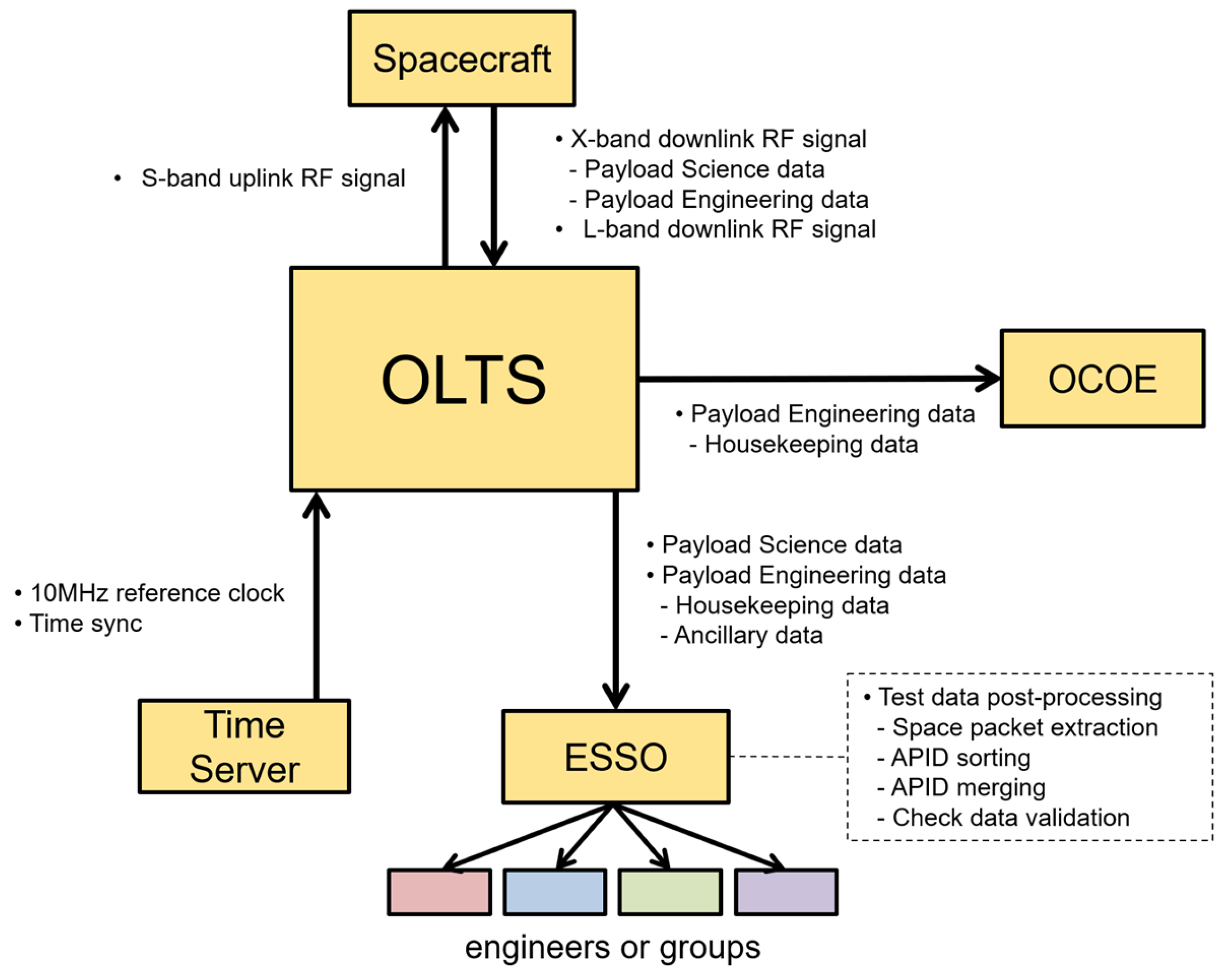
Figure 1. Simplified conceptual diagram of OLTS ground test architecture, showing RF signal flow with the spacecraft, data interfacing with OCOE for real-time monitoring, and centralized storage via ESSO for post-processing and distributed access.
Aerospace 12 00813 g001
Figure 2. An interface example between ESSO and three OLTS units deployed at separate test sites via Ethernet.
Aerospace 12 00813 g002
Figure 3. Simplified diagram showing the case where the spacecraft sorts housekeeping data.
Aerospace 12 00813 g003
Figure 4. Simplified diagram showing the case where OLTS receives all payload data and performs housekeeping data sorting.
Aerospace 12 00813 g004
Figure 5. Comparison of data transfer strategies. (a) Sequential transfer begins after testing ends. (b) OLTS enables overlapping transfer during testing, reducing total duration.
Aerospace 12 00813 g005
Figure 6. State transitions of test files in OLTS. Files with the prefix “R_” are in a closed state and either completed or undergoing transfer, while the latest file remains open state with the prefix “W_” and waits for closure to initiate the transfer.
Aerospace 12 00813 g006
Figure 7. Timing diagram of OLTS file transfer automation. Each test file triggers its transfer immediately upon entering the CLOSED state, while the next file is simultaneously created. The red dashed line marks an event where both transfer and file generation are triggered by a state change.
Aerospace 12 00813 g007
Figure 8. Structural relationship between raw test files, CADUs, and SPs in OLTS.
Aerospace 12 00813 g008
Figure 9. SPE output options for SP extraction. (a) The APID sorting produces one file per APID. (b) The merge function combines packets into a single file without APID separation.
Aerospace 12 00813 g009
Figure 10. Output files generated by SPE using the APID sorting option (Option 3) with each SP file corresponding to a single APID.
Aerospace 12 00813 g010
Figure 11. Rack-mounted configuration of OLTS and ESSO systems used for spacecraft ground testing: (a) physical setup of OLTS and ESSO units, and (b) dual OLTSs in operation during a self-validation test.
Aerospace 12 00813 g011
Figure 12. Analysis of TDT logs during Phase 1 (29 June 2016–8 February 2017): (a) number of transferred files by transfer time, (b) distribution of transfer time by test date, (c) number of transferred files by date, and (d) three-dimensional visualization of transfer characteristics.
Aerospace 12 00813 g012
Figure 13. Statistical analysis of TDT logs during Phase 1 (29 June 2016–8 February 2017): (a) mean transfer time by test date, and (b) variance and standard deviation of transfer time by test date.
Aerospace 12 00813 g013
Figure 14. Analysis of TDT logs during Phase 2 (13 February 2017–31 August 2017): (a) number of transferred files by transfer time, (b) distribution of transfer time by test date, (c) number of transferred files by date, and (d) three-dimensional visualization of transfer characteristics.
Aerospace 12 00813 g014
Figure 15. Statistical analysis of TDT logs during Phase 2 (13 February 2017–31 August 2017): (a) mean transfer time by test date, and (b) variance and standard deviation of transfer time by test date.
Aerospace 12 00813 g015
Figure 16. Processing times of SPE for 20 selected tasks recorded between 25 September 2017 and 23 March 2018.
Aerospace 12 00813 g016
Table 1. Classification of payload telemetry by data category and type.
DataCategorySubcategoryDescription
Payload telemetryScience dataObservation dataEO, SAR, magnetometer, or other instruments
Engineering dataHousekeeping dataHealth state of payload instruments
Ancillary dataInformation necessary for processing science data
Table 2. System specifications of OLTS and ESSO systems used in the spacecraft ground test environment.
OLTS ESSO
OSWindows 7 Professional x64Windows Storage Server 2012 R2 Standard x64
CPUIntel Xeon CPU E5-2620 v3 2.40 GHzIntel Xeon CPU E5620 2.40 GHz
RAM8 GB16 GB
Storage1 TByte16 TByte (Usable, RAID 5),
2 TByte (Hot Spare),
Expandable
ApplicationTDT, OLTS ManagerSPE, FileZillar Server
Ethernet Interface1 Gbps Connection1 Gbps Connection
Table 3. Test sessions during Phase 1 with more than 200 file transmissions, including the number of transferred files and the corresponding mean transfer time.
Test DateNumber of Transferred Files [counts]Mean of Transfer Time
[s]
29 June 201620937
16 January 2017135937
21 January 201739738
31 January 2017119036
Table 4. The setting of the SPE processing rule in the sorted 20 tasks.
ItemSetting
File Size3,906,252 Kbyte
CADU MergeOff
SP MergeOff
SP Sorting by APIDOn
DescramblingOff
RS DecodingOff
RS CorrectionOff
Table 5. Comparative processing durations for a 4 GB test file during Phase 1 and Phase 2.
ApplicationProcessing Time for Phase 1 [s]Processing Time for Phase 2 [s]Location
TDT (ver. 2.0)40213OLTS
SPE (ver. 2.0)144144ESSO
Total Time184358
Disclaimer/Publisher’s Note: The statements, opinions and data contained in all publications are solely those of the individual author(s) and contributor(s) and not of MDPI and/or the editor(s). MDPI and/or the editor(s) disclaim responsibility for any injury to people or property resulting from any ideas, methods, instructions or products referred to in the content.