Article

On the Structural Design and Additive Construction Process of Martian Habitat Units Using In-Situ Resources on Mars

1
Department of Architectural Technology, Faculty of Architecture and Urban Planning, University of Art, Tehran 1413915361, Iran
2
FLOW and Fluid Physics Laboratory, Department of Engineering Mechanics, KTH Royal Institute of Technology, SE-100 44 Stockholm, Sweden
3
Department of Construction, Faculty of Architecture and Urban Planning, Shahid Beheshti University, Tehran 1983963113, Iran
*
Author to whom correspondence should be addressed.
Aerospace 2025, 12(9), 761; https://doi.org/10.3390/aerospace12090761
Submission received: 28 June 2025 / Revised: 12 August 2025 / Accepted: 19 August 2025 / Published: 25 August 2025
(This article belongs to the Special Issue Space System Design)

Abstract

Taking the leap to the secondary and tertiary generations of the missions to Mars, a comprehensive outline was presented for a cluster of Martian Habitat Units (MHUs) designed for long-term settlements of research crew in Melas Chasma, Valles Marineris, Mars. Unlike initial exploration missions, where primary survival is ensured through basic engineering solutions, this concept targets later-stage missions focused on long-term human presence. Accordingly, the MHUs are designed not only for functionality but also to support the social and cultural well-being of scientific personnel, resulting in larger and more complex structures than those typically proposed for early-stage landings. To address the construction and structural integrity of the MHUs, the current work presents a comprehensive analysis of the feasibility of semi-3D-printed structural systems using in situ material to minimize the cost and engineering effort of logistics and construction of the units. Regolith-based additive manufacturing was utilized as the primary material, and the response of the structure, not only to the gravitational loads but also to those applied from the exterior flow field and wind pressure distributions, was simulated, as well as the considerations regarding the contribution of the extreme interior/exterior pressure differences. The full analyses and structural results are presented and discussed in this manuscript, as well as insights on manufacturing and its feasibility on Mars. The analyses demonstrate the feasibility of constructing the complex architectural requirements of the MHUs and their cost-effectiveness through the use of in situ resources. The manuscript presents an iterative structural optimization process, with results detailed at each step. Structural elements were modeled using FEM-based analysis in Karamba-3D to minimize near-yielding effects such as buckling and excessive displacements. The final structural system was integrated with the architectural design to preserve the intended spatial and functional qualities.

1. Introduction

Limited by the local materials for most of the construction elements and the possibility of having the material processing to the minimum level of complexity, a planetary space mission will be bound by in situ resources. The further the mission is to be executed along the human space technology development, the more access there might be to non-local, but still in situ, materials for the construction. However, as far as the construction methodology is concerned, the financial and engineering costs always demand local construction instead of the transformation of already assembled parts to the site. Considering the design of a cluster of Martian Habitat Units (MHUs) on the surface of Mars (Figure 1), located in the central segments of Valles Marineris as a research base for the second generation of landings on Mars [1] translates to the utilization of regolith as the base material through additive manufacturing of the major parts of the constructions. This manuscript addresses the technical ramifications of this subject matter.
In the case of construction in conditions of a remote place, such as planets and moons of the solar system, there are huge challenges that do not exist in the construction processes on Earth. In this paper, a functional structural method is chosen among different techniques from the literature, and in the next step, the feasibility of the chosen system is simulated and analyzed for the harsh conditions on Mars. In addition, one might consider the current attempt to validate the applicability of the mentioned model in the context of space architecture.
Additive manufacturing (AM) technologies have already been used in space since 2014, when NASA launched the first polymer 3D printer for fused deposition modeling (FDM) on board the International Space Station (ISS) to investigate the potential of AM in microgravity [2,3]. The advantages of AM for human space habitats have been discussed in various fields: in the construction of space structures, fabrication of spare parts, food preparation [4], use of bio-plastic as an option to print the everyday life items and tools such as cups, containers, clothes, or even insulation materials [5] and printing medical and surgical instruments for long-duration space missions [6,7].
From an architectural perspective, generally, seven viability factors should be evaluated when selecting a construction method, including materials, structural design, process efficiency, logistics, labor, environmental impact, and cost. Although, there are few studies that analyze the feasibility of 3D printing in different environments [8] and a complex trade-off may be needed to select the most applicable concept [9], several studies show that in remote and hazardous places, areas with rugged terrain, inhospitable climates, or inhospitable environments, autonomous 3D printing construction can be an efficient solution [10,11].
In recent years, although the launch costs have been reduced by the contribution of private companies, one study estimates it could cost as much as USD 1 million per kilogram to transport material and supplies to Mars [12]. These numbers suggest that supplying a mission with surface stay is not financially sustainable with conventional methods [13]. The use of 3D-printed construction in space offers several potential logistical advantages, such as eliminating the need to design construction components to withstand launch loads and space travel conditions while minimizing launch mass and volume, hence the costs [12].
Furthermore, in situ resource utilization (ISRU), regarding the available material on-site, and rapid prototyping construction methods eliminate and reduce human efforts and health risks and, more importantly, the entire mission cost, allowing for the infrastructure construction by robots before human presence and on-site maintenance later [4,9,14]. Also, this method allows architects and engineers to design more geometrically complex structures with minimal material waste and post-processing while offering the advantage of parts consolidation and fabrication in comparison to conventional methods [14,15,16]. Overall, 3D-printed construction is capable of the same strength as cast components (i.e., masonry components) and improved mechanical and thermal properties compared to conventional construction. These components are also capable of being designed and printed based on the exact loads they are supposed to handle [17]. Specifically, for a Martian habitat, the extreme temperature gradient that results in thermal stresses and further increases the structural stresses in the building envelope of the pressurized environment in the absence of a thick atmosphere, thus increasing leakage risks, and large amounts of radiation exposure must be considered [18]. For this reason, one key element that should be considered in the field of construction on Mars is selecting materials that have the most compatibility in terms of functionality to weight (and/or cost) ratio, within the context of a space mission. Apart from stability, durability, and availability as raw material on Mars, energy consumption should also be minimal during material processing [19].
All 3D-printed materials must be processed to withstand tensile forces due to the pressure differences [20]. Some materials are proposed for use in space construction, such as basalt, sulfur, recycled plastics, and metal. Several studies propose leveraging the abundant in situ material resources found on Mars, namely, regolith, the crushed rock and dust covering the lunar and Martian surfaces, which is produced through long-term space weathering processes. These processes include not only micrometeorite impacts over millennia but also particle irradiation and other physical and chemical alterations induced by the space environment [21], basalt, an igneous rock formed during lava flow, and sulfur, a material particularly common on Mars that can be used as a fundamental ingredient or alternative binder in concrete [22,23]. However, Martian regolith contains perchlorates that are toxic to humans, and therefore, direct or indirect regolith exposure must be eliminated. Plastics such as HDPE (i.e., high-density polyethylene, a type of thermoplastic petroleum-based polymer) can be produced using local ethylene resources on Mars and used to provide a non-porous boundary layer for air-tight structures, a layer of shielding from potentially toxic regolith [20]. As another option, concrete is the most common material used in 3D-printed constructions, and it is the best choice for remote environments [24]. However, the material properties and requirements of printable concrete differ from the conventional concrete that is used in common structures, and yet there is the challenge of making reliable rheology from in-space resources [25]. Moreover, the lack of tensile strength and ductility due to a lack of reinforcement is, for example, one major challenge for structural applications of 3D-printed concrete [20].
Previous design proposals for on-surface Martian habitats have tried to address the construction challenges in harsh conditions of Mars and the moon; for instance, Foster and Partners’ lunar habitation [26] with European Space Agency, uses regolith as the main construction material but instead of printing the habitat, they fuse the layers by a robot-operated 3D printer to create a protective shell, the tubular base module and its inflatable dome [26]. NASA Langley’s Mars Ice Home suggests the use of inflatable plastic and ice as the main construction material since it could be more effective in radiation shielding than the regolith [27]. SEArch+ (Space Exploration Architecture) and Clouds AO, who propose the Mars Ice House, investigate the possibility of printing solid ice with iBO bots that use a triple nozzle to dispense a composite of water, fiber, and aerogel along with layered rings, printing a translucent, insulating lenticular form that is structurally stable [28]. SEArch+ and Apis Cor’s X-House 1 and 2 use Martian concrete reinforced with basalt fibers and expandable polyethylene foam to 3D print the habitat [20]. AI Space Factory’s MARSHA used a biopolymer basalt composite material for 3D printing, which has a high hydrogen concentration and, to some degree, provides shielding against radiation and is effective against stress. The Pennsylvania State University used sulfur concrete with basalt aggregates, which would require no water, and magnesium oxide mixtures that would set very quickly. They also developed a dry geopolymer binder called MarsCrete™, composed of minerals indigenous to both Mars and Earth. Apart from that, the use of recycled lightweight aggregates with insulation properties to create functionally graded concrete, providing an external layer of thermal and radiation protection, and optimizing the design for structural performance were considered [29].
Currently, the construction scale rapid prototyping is in the early stages of development. Moreover, the 3D printing methods used on Earth have to be adapted and redesigned for Mars or moon missions to build habitable structures [20]. Earlier technologies, such as the Monolite/D-Shape technology, Contour Crafting (CC), and FreeForm Construction machines, were introduced that extrude and deposit material in a layer-by-layer manner. Each of them utilizes slightly different deposition methods, processes, and materials [26]. D-Shape is a large printer that selectively binds the spread-out material, with the desired thickness, using a binding material spread out from a spreading nozzle on the print-head, similar to the selective laser sintering (SLS) printing process [30]. In Contour Crafting, the print material and a fast-hardening binder are extruded through a programmed nozzle that can make direct printing of computer models. The final product has a better surface quality since the surface is smoothed by a trowel [16]. Moreover, it offers higher building speed and a wider range of material choices. In concrete printing, which is similar to CC, the printing nozzle follows a pre-programmed path and continually extrudes concrete materials [30]. The FreeForm Construction machine uses a principle like fused deposition modeling (FDM) technology [24]. In recent years, Branch Technology pioneered cellular fabrication (C-FabTM) with FreeForm 3D printing, where material solidifies in free space as it is printed. Using topology optimization and sequencing algorithms to print cellular matrices in midair without formwork (i.e., the process of additive manufacturing, where the printing occurs without local holding of the structures through means of support or scaffolding), allows optimized material density to be placed where it is needed to better resolve the loads while reducing the costs and material wastes [29].
The large-scale construction 3D printing technologies and the used materials should, in principle, have an acceptable degree of extrudability, flowability, buildability, and suitable setting time with satisfying mechanical properties to form a continuous paste [30]. Further improvements in the development of optimization techniques of material processing can enable multi-material 3D printing on larger scales. This will allow precise control of different material combinations and their positions to better manipulate the multifunctional properties and responses of the final product (e.g., mechanical strength, etc.) to suit the defined requirements [31]. Despite the strong tendency toward continuous structural construction in 3D printing, Konstantatou et al. [32] argue that discrete manufacturing, or a component-based approach to design and construct extra-terrestrial structures, would offer advantages with regard to reusability, efficiency, and costs. This opinion is also in line with the modular habitat design suggested by [1].
Many other crucial parameters play key roles in a 3D-printed structural performance, like overall print quality, steel reinforcements, print time, print direction, and standards. Although the lack of codes and standards is one of the challenges with this structural system, this matter may not be an issue in some remote environments, where 3D-printed structures are more reliable and sounder than existing makeshift structures [8]. However, the current technology and construction procedures must be modified for Mars or moon missions. For instance, machinery, mobile 3D printers, robotic arms, and mobile platforms must be lightweight and deployable to fit the launcher constraints [20].
As a continuation of the research started by the communication of the first design paper [1], this manuscript provides detailed insight into the realization of the construction and structural aspects of the Martian Habitat Units (MHUs). There is a plethora of research following the first paper, proposing the initial design of the units from the architectural and space technological viewpoints, such as [33], on the methodical design procedure of relevant complexes targeting the prerequisites of deep space missions.
This manuscript provides comprehensive results on the structural design and implementation of in situ resources for the realization of the design proposed in Amini et al. [1], namely, the Martian Habitat Units (MHUs). The primary introductions on the specifications of the design, its initiating concerns, and operational conditions are followed by detailed analyses of the requirements of such a design from structural and constructional points of view, the deducted essentials of which are then provided as guidelines in further sections of the manuscript on which the methodology of the structural integrity simulations is constructed. The results of such investigations are then reported in Section 6 of the manuscript, alongside a discussion on the modifications the design has gone through for better compliance with the construction concerns and architectural needs.

2. The Case—Martian Habitat Units (MHUs)

Martian Habitat Units (MHUs) are designed as a response to the needs of a scientific crew living on Mars for the span of several years. Each 10 MHUs are oriented in a circular cluster, forming a small village with the capacity of up to 90 research crew members. The interior of the cluster is allocated to house a solar farm as the main passive source of energy for the MHUs, interactively functioning with other sources of power such as wind turbines and nuclear fission reactors, as is discussed in the following sections [1].
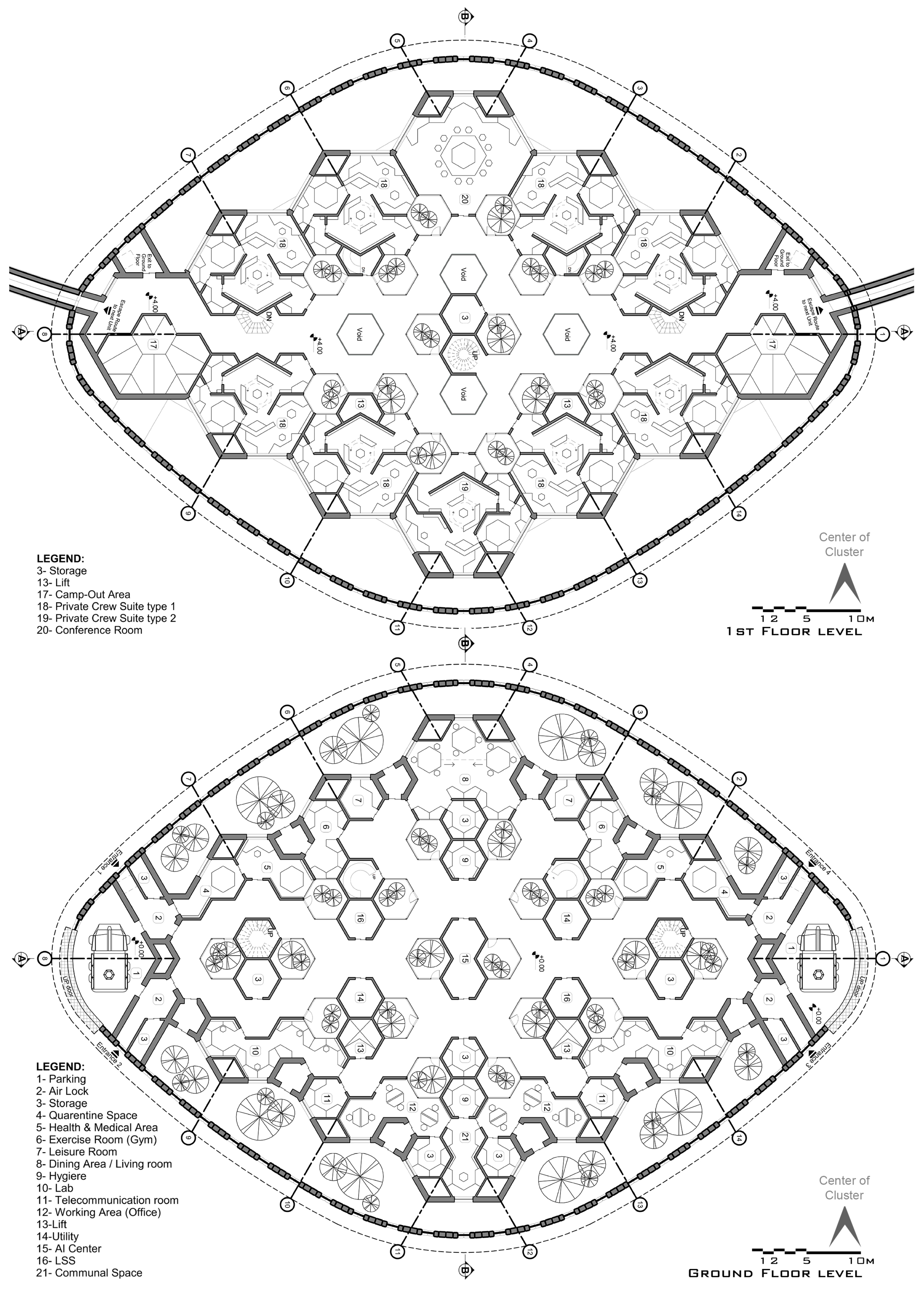
Each MHU is equipped with medical rooms, labs, office-type work areas, telecommunication, and AI centers, as well as systems rooms where the components of the Life Support System (LSS) are located on the ground floor. And on the first floor, there are private suites for crew members, emergency escape routes to the neighboring MHUs, and access to the second floor, which includes only the central regions of the plan and is solely designated for emergency cases as a bunker (Figure 2).
As the general aspects of the design of the MHUs are discussed abundantly in [1] from a space technological perspective, and conditions of the design from the perspective of natural lighting supplementation are discussed in Amini et al. [1], this section would be focused more on the specific aspects of the design pertaining to the structural integrity of the MHUs.
The enveloping garden (the term used from the original design presented by [1], referring to the exterior garden area enveloping the interior of the MHUs) around the exteriors of the ground and first floors plays the role of an intermediate membrane. This intermediate level functions in many aspects, such as lighting (semi-natural lighting concept discussed in [34], air pressure (the pressurized vessel concept discussed in [1,33], breathable atmosphere, etc. The interior of the MHUs is kept at the standard sea level (on Earth) atmospheric pressure, while the exterior of the units, i.e., the atmosphere of Mars, reaches pressures less than one percent of that. This gap, which is to be supported by the structure of the MHUs, is bridged through an intermediate medium, as discussed above, where the vegetation does not require more than 85% of the atmospheric pressure needed by the crew [35,36]. And since the presence of crew members in the garden is also intermittent and temporary, they will not be subject to any harm in that regard, either. This consideration, which eases the tension of inflation on each of the layers of the façade, as the gradual pressure differences are supposed to be addressed with lighter structural elements, has been named the “double-layered pressure vessel” throughout the documentation published on this research.
Secondly, the modular design of the MHUs is to be discussed, as it will have a direct impact on its structural system and configuration. The primary mode for the design of the MHUs is chosen to be hexagonal modules. The whole plan is composed through a rhombus configuration of 4 by 4 hexagons of the maximum size for the interior of the design and then engulfed by the curved exterior façade of the surrounding garden. However, to maintain a higher level of flexibility in the juxtaposition of the possible sub-geometries, three lower layers of hexagonal patterns are interwoven within each of the primary modules. The geometric details of the modules are presented in [1].

2.1. Mission Specifications

To better understand the scope for which the MHUs are designed, this section presents a brief report on the specifications of the underlying mission considered as a baseline for the design of the MHUs. More detailed specifications of the mission are discussed in [1,33], whereas more details on the fundamentals behind such strategical design of human missions are available in [37].
The mission is defined for the pre-terraforming era on Mars; however, the first generation of missions have already been performed.
The crew is composed of educated adults, spending years-long residence in the MHUs for the purpose of on-site expeditions of the planet.
There are flights available on and off Mars to Earth and the orbiting space stations.
The community is populated, and thereby designed for, up to 1000 crew members.
The research crew work full time on their tasks, and MHUs are responsive to the rest of their leisure time as well, since the duration of the mission dictates the presence of concepts such as lifestyle to a larger extent than what is currently available for the crew members of, for example, the ISS.

2.2. Operation and Geometry

For the details of the design of MHUs in the published literature such as [1,33,34], this section presents the primary information of the habitat design in an extremely brief manner, and the audience is strongly advised to refer to the mentioned works for more insight on the details of the design.
MHUs are designed to respond to the needs of the research crew staying on the surface of the planet for longer periods than is theoretically allowed by the orbital dynamics of the Earth–Mars flights. The functionality of the MHUs to the biological, psychological, and operational needs of the crew, as well as their robustness against the extreme conditions of Mars, is of the utmost essence.
The crucial Life Support System (LSS), consisting of physiochemical and bio-regenerative systems, secures the survival needs of the crew in the closed environment of the MHUs by keeping the unit interior at its optimal operational level. The atmosphere management subsystem provides recycled breathable air, with bearable pressure, temperature, and humidity. The water management subsystem recycles wastewater into potable water. The waste is processed and separated accordingly via the waste management subsystem. Apart from those, these subsystems have the responsibility of monitoring, detecting, and removing the probable particle and microbial trace contaminants. An important feature of the MHUs, which is in close correlation with the LSS, namely, the enveloping garden, is the main food supply source while providing visual comfort for the crew and functioning as a pressure buffer with 0.85 atm, between the interior 1 atm and the Martian atmospheric pressure of ~0.006 atm. Moreover, noise control systems, light regulation, smart windows, and an ergonomic design are considered to keep the crew in the defined comfort zone. Robotic aids and telepresence have also been widely considered to eliminate/minimize human labor for the construction and future maintenance of the units.
The units are to be mainly powered by constantly reliable active energy sources to ensure safety during the seasonal and unforeseen fluctuations of the passive/renewable resources available on the surface of Mars at the site location, namely, the central regions of the Valles Marineris. To provide the roughly 3300 kWh/day estimated total power consumption per MHU (9 crew members), calculated with a high safety factor, a minimum of 18 and a maximum of 27 reliable configurations of modular 10 kWe-class Kilopower reactors have been considered per MHU based on the number of settlers in each unit. As a secondary backup power source, in the middle of the cluster of 10 MHUs, a solar farm is designed with a 3400 m2 area of PV per MHU based on the lowest daily radiation received on a tilted surface of PVs with 33% efficiency. In order to utilize the storm energy during dust seasons when PV efficiency drops further, a configuration of 5 horizontal-axis wind turbines (HAWT) has been considered as the tertiary backup power generation source.
Each MHU is designed coarsely in a rhombus shape, composed of a 4 by 4 array of hexagonal modules. The garden that envelopes the entire plan has its exterior formed by three sets of circular segment curves: a sharp curve of low radius at the circumferential corner of the plan, a relatively wider one at the radially located corners, and a segment of a much larger circle to mimic the sides of the rhombus plan. To give a better understanding of the scales of the designed MHUs, one should note that the exterior façade is created through a closed loop of 58.71°, 16.12°, and 89.05° arcs of circles with 25.83, 98.69, and 8.13 m in radius, respectively.
To have a better grasp of the geometry of the mentioned modular design, it could be noted that the largest layer of the hexagons, also denoted as the 4th layer, is the major block of the 6.49 m hexagonal pattern that sweeps the plan of the MHUs. There is a 3rd layer hexagon located in each main module concentrically; however, with a 30-degree rotation around its center, which results in the side length of 3.75 m. Placing seven second-layer hexagons inside the main module, with their sides parallel to the main module’s orientation, allows the side length to be 2.16 m. And continuing one step further with the same reverse growth rate, the first layer modules are obtained with a side length of 1.25 m. More details on the specifications of the hexagonal modules are to be found in [1], Section 8.5. In light of the core scope of this manuscript, it should be noted that the architectural, structural, and system-level design of the components must obey the geometric juxtapositions enabled by this modular design.
The entire unit interior and garden area are then extruded for two stories to build the ground and first floors as the main bulk of interior areas. The ground floor is considered to house the work areas, labs, medical and communication centers, service areas, lots for subsystems, electrical, and mechanical devices, while the first floor holds crew private residential suites. In the central, mostly 2 by 2, array of the main hexagonal modules on the second floor, a bunker is devised for extreme emergency cases, for when the crew needs shelter while waiting for the arrival of rescue teams. On the same level, i.e., the top of the first floor, where the exterior atmospheric conditions govern, a flexible, yet robust, membrane is extended all over the MHUs’ top side and is kept in a paraboloid geometry by hydraulic jacks, as well as being inflated by compressed Martian atmosphere from below, using a safe-fail redundant set of compressors. This anti-dust-settlement membrane, or ADSM for short, is capable of morphing to maintain different heights and serves as a flow-controlling technique to control the separation of the exterior flow field on the MHUs and reduce the amount of dust settlement on the central regions of the cluster, where the solar farm is located, in dust storm seasons. More information regarding the functionality and operation of the ADSMs, as well as their geometrical design, is presented in [1].
From an architectural perspective, a number of structural considerations are predicted in the initial design. The hexagonal modular pattern, which is used in the 1st step of the design phases, has provided a context in which the distribution of vertical loadings can be possible through different kinds of structural systems. Plus, there are places designed at the end of each axis (i.e., grid) that are designated to situate structural columns.
Generally, any structural design must be calculated to resist lateral and vertical loads. Like on Earth, vertical forces on Mars are caused by gravity and include the so-called live and dead loads of the weight. The considered lateral loads on Mars include wind, quakes, and air pressure differences, the latter of which is quite different from a construction project on Earth. The main challenge, therefore, in the structural design of the MHUs is the fact that the exterior envelope must resist the force applied from the interior side caused by the pressure difference. In this paper, these loads are calculated, and then, the proposed structural system is simulated and analyzed to examine its reliability.

2.3. Summary of Features

To enhance the readability of the manuscript, we provide a brief list of features of MHUs, linking them to the adequacy of the design in response to the mission/environmental conditions (also see Figure 3):
Mid-size population: Each MHU houses 9 crew members, which is large enough to have a variety of expertise for technical, medical, and mission-specific areas.
Mid-size community: Each cluster houses 90 crew members, for a more diverse local combination of tasks and societal duties.
The enveloping garden area provides food, visual comfort, and serves as a mid-pressure bridge between the high-pressure interior of MHUs and the low-pressure Martian environment [1,34].
Multilayer fail-safe redundancies in passages, shelters, airlocks, equipment, LSS, gates, hatches, etc.
Multi-source power supply systems range from passive, semi-passive, to fully active fusion-based systems.
Emergency-state connectivity between MHUs in a cluster and detailed design for a versatile range of evacuation/sheltering scenarios [1,33].
Functional areas located at an inverse-proximity order to the entrance gates (with airlocks, quarantine, and medical units closest to the gates, whereas leisure and private segments are located further from it).
ADSM design provides flow control and streamlining to the exterior of MHUs, and maintains the minimum dust settlement in the central regions of the clusters, thereby minimizing maintenance and cleaning time and cost for PVs during the dust storm seasons.
Natural lighting resources are considered in the hierarchy of architectural design, with the private suite and office/lab areas placed in the periphery of the MHUs, adjacent to the enveloping gardens to minimize the energy consumption needed for artificial lighting [38,39].

2.4. Environmental Conditions

NASA’s Human Research Program (HRP) categorizes human space flight hazards into five major categories: altered/low gravity, radiation, distance from Earth, isolation, and hostile/closed environment and spacecraft design. The environmental hazards of a long-term human Mars mission, its psychological and physiological health risks, and possible strategies to reduce the dangers have been discussed comprehensively in (Amini et al., 2022). In this manuscript, the Martian conditions are elaborated with an emphasis on construction.

2.4.1. Gravity

The gravity on Mars is only 37.8% of that of the Earth. Therefore, more atmospheric gas has escaped and resulted in a low-density Martian atmosphere. Studies show that the gravity varies on Mars’ surface in the range between 3.68 m/s2 and 3.75 m/s2; Valles Marineris stays in the middle of this range [40].
Although human functionality in low gravity declines and possible physiological issues arise that need careful monitoring and effective countermeasures, it is assumed that low gravity is in favor of construction with regard to lower overall compression and buckling loads in comparison to the Earth. However, considering the construction methods, specifically the additive manufacturing in low gravity, and how it affects heat flow, the settlement, slope, density, and the mechanical behaviors of the printed specimens, further research and development are needed.
NASA has been experimenting with 3D printers onboard the space shuttles during zero- and high-G, and now, in the microgravity of the ISS on smaller scales and for various scientific research fields, e.g., 3D printing of biological tissues [41], 3D printing of parts with a polymer-based material using a fused filament fabrication (FFF) printer [42] etc., to investigate the viability of printing in different environments. Research teams such as Penn State University have sent a sample of a 3D-printed complementary cement mixture and water to the ISS to further explore the material’s behavior in microgravity conditions [29], yet understanding how printed structures behave in microgravity with long-term exposure and their fixity is a further challenge [43] and the development of new design standards and evaluation criteria are of great importance [30].

2.4.2. Atmosphere

In contrast to Earth, the Martian atmosphere consists of only 2.59% nitrogen and 0.16% oxygen. The largest proportion of it (~95.1%) is carbon dioxide, which continuously changes phases between gas and dry ice depending on the temperature variations.
The average atmospheric pressure on Mars is about 0.636 kPa, less than 1% of that of the Earth, and due to seasonal CO2 condensations at the polar regions, it varies 20% each year [44]. Viking Landers have recorded wind speeds typically between 0 and 5 m/s with maximum solar-averaged speeds up to about 12 m/s with ± 10% measurement accuracy [45].
Considering the main dust lifting events on Mars, dust devils (convective vortices) occur locally on smaller scales when compared to dust storms. The Martian atmosphere lacks moist convection but responds strongly to air-borne dust heating [46]. Despite its low heat capacity, the heat transferred from the surface to the atmosphere controls the size of dust devils and likely other dynamic processes in the atmosphere [47]. Dust storms are categorized into local (turbulence), regional (slope winds and gravity waves), and global scale dust storms based on their size and spatial distribution [46]. Local and more frequent dust storms occur in both hemispheres all Martian year-round, although during local autumn and winter in mid-latitudes of each hemisphere, an increase in dust storm frequency is recorded. The combination of multiple local dust storms usually creates regional dust storms that are estimated to happen 8 to 35 times per Martian year. Global dust storms are commonly initiated when local and regional dust storms grow and merge. They occur in interannual variability, which, in some years, manifests itself as dramatic, planet-encircling dust storms covering all longitudes, and their consequent effects on the thermal and dynamical structures of the lower atmosphere last longer (~60 sols) [48,49]. Recent studies suggest that global dust storms transport water vapor from the lower to the middle atmosphere and increase its escape rate. These storms further contribute to this water loss process by increasing the atmospheric temperature, due to greater radiation absorption during the daytime, and reducing ice cloud formation [49,50].
Multiple studies suggest the possibility of utilizing Martian atmosphere components as an input to the LSS to generate breathable oxygen for the habitat. Amini et al. [1] also propose the idea of utilizing storm energy as a backup power generation source. However, the complex climate of Mars, its low atmospheric pressure, and atmospheric dynamics define an important challenge in constructing a long-term large habitat. As the habitable interior should maintain 1 atm bearable pressure, the structure must prevail over the lateral loads of the pressurized air pushing outward on the interior walls and leakage while also bearing the external wind loads. The construction process itself prior to human arrival can also be affected by winds [51].
It has been reported that the particle size of Martian dust suspended for long periods is 1–2 μm, and dust particles raised into the atmosphere by wind and dust devils are smaller than 5 μm [52]. Dust-lifting events may result in faster degradation and erosion of the habitat exterior as well. Hence, regular dust mitigation considerations for the habitat unit, as well as PVs, wind turbines, and other instruments, should be considered.

2.4.3. Temperature

Mars, with a 1.5 AU (2.28 million km) distance from the Sun, receives about an average of 586.2 W/m2 solar radiation. The average temperature on the surface of Mars is −63 °C with a daily temperature gradient of 60 °C [44]. Furthermore, while differences in atmospheric pressure and temperature along the longitude of Mars can cause dust storms, the longer seasons and dust storms also cause large fluctuations in temperature [47,53].
The main challenge to face in habitat construction is the thermoelastic cyclic loads applied to the structure because of the extreme temperature gradient, not only on a daily/seasonal basis but also considering the difference between the habitable room temperature of the interior and the average surface temperature of Mars. This dictates both the material choice and the use of multilayer insulations (MLI) to maintain the interior temperature and structural measures to eliminate leakages. For instance, a concrete combination of Martian regolith and molten sulfur binder has been shown to be feasible for the Martian temperature ranges [54]. Apart from that, the 3D printer technology used for manufacturing, its extrusion temperature, and the final material quality are also highly dependent on the surrounding temperatures. Hence, during the autonomous construction with compatible materials, measures should also be taken to ensure the print quality of the structure since the temperature affects the deposition and solidification of the printed material and, therefore, its microstructure [42,51,55]. Reches [56], for instance, has also proposed multiple concrete formulations, including materials available on-site that can be processed and cured in low temperatures on Mars.
Large temperature differences can be utilized as an in situ energy source [53] or in LSS atmosphere management components such as a temperature-swing absorption plant (TSA) that functions via the changes in ambient surface temperatures during the day–night cycle [57].

2.4.4. Radiation

Due to the absence of a global magnetic field and dense atmosphere, Mars is exposed to radiation from both galactic cosmic rays (GCR) and solar particle events (SPE). High-energy GCR that travel at the speed of light can penetrate the spacecraft, habitat, and human body, causing densely packed ionization events in the molecules. Consequences are cellular structure damage, central nervous system disorders, and late cardiovascular damage, to name a few [58,59,60,61].
Several studies have suggested subsurface habitats to reduce radiation exposure and provide better thermal insulation in more stable underground temperatures [18]. Rather than burying the habitat underground [1], with the goal of providing the crew with natural lighting and psychological well-being, propose an above-surface habitat design that plans to reach acceptable standards with passive and active shielding against radiation and further countermeasures to ensure crew safety in both short and long-term missions.
With regards to construction in the current design, the material choice, insulation, and wall thickness shall act as passive radiation shields. The use of ice, materials with high hydrogen concentration, Martian regolith and basalt, thermoplastics such as ABS, fibrous and cementitious materials, and polyamides are the state-of-the-art research to tackle the radiation exposure problem of human Martian exploration missions.
Moreover, prolonged exposure of the materials to space radiation also causes degraded performance of the thermal, electrical, mechanical, and optical systems, and outgassing leads to molecular contamination [2,51,62]. Hence, a modular design of habitats can be beneficial in the maintenance and replacement of damaged parts. Apart from that, autonomous robotic construction should be utilized to eliminate human participation during construction.

2.4.5. Geology

Martian surface landforms, mineralogy, and regolith composition have been investigated by the visible to short-wavelength infrared (VSWIR) orbital observations of the planet, the Observatoire pour la Mineralogie, l’Eau, les Glaces et l’Activité (OMEGA) of the ESA Mars Express mission [63], the Compact Reconnaissance Imaging Spectrometer for Mars (CRISM) [64] of the Mars Reconnaissance Orbiter (MRO) [65], and the landed rovers.
The Martian surface is mainly composed of dust-covered regions and southern highlands. The landforms consist of plains, mountains, canyons, basins, volcanoes, and polar caps. There is a general latitude-dependent mantle, including sub-terrain water ice, with high impact on the design of the human missions [66]. Duricrusts are distributed in mid-latitudes and dust-covered rock, and soils with shallow ice are distributed in polar regions [67]. Viviano-Beck et al. [68] have listed the types of locations of the mineral spectra, indicating a diverse variety, such as H2O and CO2 ice, iron oxides and mafic silicates, phyllosilicates, carbonates, sulfates, halides, and other hydrated silicates. The Mars Odyssey orbiter also found that the Martian surface is covered by basalt, some of which is rich in olivine. According to the new data from the Mars rover InSight, the layers beneath the surface are dominated by dust, regolith, and large rocks [53].
It is detected that Mars is a moderately seismically active planet, and based on the collected data of the InSight, Marsquakes occur with energies approximately between 0.1 and 10 Hz and mainly of magnitudes less than 4 MW [69,70].
Due to the fact that no Martian regolith has been returned to Earth, Martian regolith simulants are used to simulate the chemical and mechanical properties of Martian regolith for research and experiments, designing and testing prototype rovers, developing excavation tools, and other instruments for Mars missions, and last but not least, the construction of Martian infrastructure via in situ resource utilization [71]. A variety of Martian regolith simulants have been designed previously, such as NASA’s Johnson Space Center JSC Mars-1 [72] and Mojave Mars Simulant (MMS) and its updated version MMS-1 [73], the open-access mineralogical standard Mars Global Simulant-1 (MGS-1) developed by the University of Central Florida to better represent the Martian global basaltic regolith [74]; Johnson Space Center-Rocknest (JSC-RN) manufactured by NASA’s Advanced Exploration Systems (AES) ISRU project to simulate water extraction experiments from Martian regolith [75]; and Jezero Crater simulant JEZ-1 developed by the CLASS Exolith Lab at the University of Central Florida to investigate the geotechnical characteristics of the Martian soil [71].

3. Construction Specifications

3.1. Material

As previously mentioned, utilization of in situ resources and 3D printing for large construction in the harsh conditions of Mars may be the most feasible method. However, there are several important challenges that should be addressed: the construction material, for instance, which is the deciding parameter that defines the structural performance, and its construction technology. Furthermore, the choice of the material has a direct impact on the design of safety measures against temperature variations and radiation. Unfortunately, at the time of this writing, despite the agreement among the scholars that Martian regolith will be used as the main component of future Martian construction, we currently lack the precise mechanical properties of the regolith due to the simple fact that no sample has ever been returned to Earth from Mars. The physical and chemical properties of the Martian regolith have been investigated at length and are detailed in the literature based on the findings of the Martian rovers, and the abovementioned simulants have been produced to allow for an approximate simulation of the regolith behavior in various conditions. The revealing effects of the meteorites as indicators of the geochemical processes on Martian regolith are also worthy of mentioning here [76].
With every robotic mission on Mars, the simulants have been updated, and assuming the comparable properties to those of the Lunar regolith, have been tested and reported in the literature. Apart from that, alternative composite materials have been introduced in an attempt to theoretically enhance specific properties of the construction material. For instance, adding certain additives and/or cement to the regolith may improve not only the compressive strength of the material but also, crucially, its tensile strength, since the low Martian gravity is in favor of compressive loads, but the low density of the Martian atmosphere induces a large pressure difference in comparison to the habitable area of the units, which manifests itself in tensile loads on the surrounding structure. Since Martian construction is still being compared to the construction on Earth, very few studies have seriously considered examining the tensile behavior of the simulant or composite concrete. Furthermore, as the material treatment, the construction method, and the construction environment on Earth considerably affect the mechanical behavior of the final product, it is inaccurate to assume that the evaluated and reported parameters are interchangeable for other design and construction decisions.
Despite the lack of accuracy, in order to proceed with the structural simulation of the proposed design, the materials and their available mechanical behaviors obtained from the specific studies, their specific test conditions, advantages, and disadvantages regarding ISRU and AM are presented in Appendix A. The processed regolith into cast and sintered basalt suggested in [77], with 490 MPa compressive strength, 14 MPa tensile strength, and 73 GPa Young’s modulus, the chosen material as the software input for the structural analysis.
A more comprehensive description of the state-of-the-art in the materials relevant for space technology and habitation manufacturing is presented in Appendix A.

3.2. Wind Loads

3.2.1. Governing Equations

In the present manuscript, we have used a time-dependent numerical scheme, U-RANS (unsteady Reynolds averaged Navier–Stokes) Equations (1)–(4), coupled with k ω SST (shear stress transport) turbulent model, and Equations (5) and (6), most suitable for surface-mounted bluff body simulations. More details on the governing equations are available in Appendix B.
ρ t + · ρ v = S m
t ρ v + · ρ v v = · p + τ ̿ + ρ g + F
t ρ H + · v ρ H + p = · k e f f T + S  
τ ̿ = μ v + v T 2 3 · v I
t ρ k + x i ρ k u i = x i Γ k k x i + G ω ¯ Y k + S k
t ρ ω + x i ρ ω u i = x i Γ ω ω x i + G ω ¯ Y ω + D ω + S k

3.2.2. Domain, Grid, and Boundary Conditions

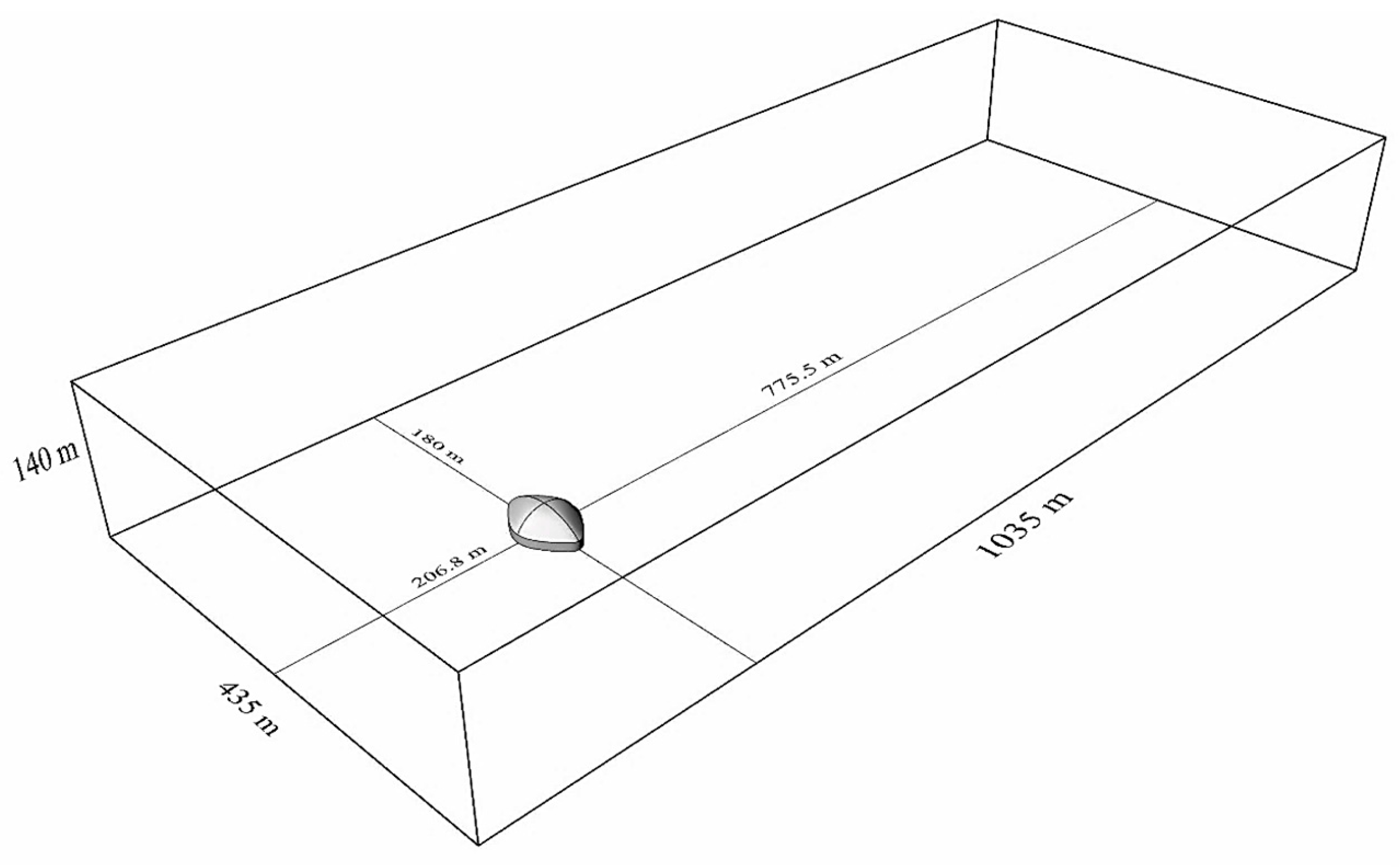
As the convention dictates, 1D blockage ratios of less than 17% in the vertical and spanwise direction of the case geometry inside the rectangular domain will result in an overall blockage ratio of less than 3% [78]. The same values have been chosen for this study, which have resulted in the domain dimensions shown in Figure 4. It should be mentioned that the streamwise depth of the domain and the position of the case with respect to the inlet of the domain have been calculated through previous wake sensitivity analyses in similar building exterior flow field studies [38,79].
For the assessment of the worst-case scenario in terms of the maximum wind loading on the building façades and foundation, the maximum deployment of the anti-dust-settlement membrane (ADSM) has been considered. The MHU in question is oriented with its secondary axis parallel to the wind inflow direction. This will correspond to the case of wind configuration inward toward the center of the cluster, seen from the viewpoint of the MHU under study. To solve the flow field numerically, the entire domain has been carpeted with computational grid cells. As the gradients are much higher in the near-wall regions of the flow field, the boundary layer mesh with much higher concentration of the nodes is implemented on the solid surfaces of the geometry, and the rest of the domain has been filled with tetrahedral mesh elements, as advised by [80,81].Table 1 summarizes the specification of the numerical mesh.
To capture the effects of the atmospheric boundary layer on the surface of Mars, the log power wind profile has been used:
U z = U * κ ln z z 0  
where the substitution of the numerical values for the aerodynamic roughness length and von Karman coefficient [82] and a super extremal wind velocity magnitude equal to 30 m/s at the height of 40 m above the surface will result in the following simplified function.
U S E z = 4.0623 ln 40 z  
As a simplified approximation, the composition of the Martian atmosphere is considered to be 100% CO2, and for the site location, it is considered to have the average temperature of 205 K, corresponding to the temperature at the surface, around the middle of the dust storm season, namely, Ls = 270 (Mars Climate Database—MCD v5.3 [83]). The above conditions are maintained while the interior temperature of the MHU is kept at 295 K based on the instructions on the comfort condition of the residents [84]. In addition, the density of the atmosphere close to the surface is set to 0.020 kg/m3, while the kinematic viscosity constant is equal to 0.001 kg/ms. And lastly, it is worth mentioning that the simulations have been performed for the physical duration of 10s, with an unsteady time resolution of 0.01 s.

3.2.3. Intermediary Results—Flow Field

As mentioned above, the effects of the exterior atmospheric flow field have been considered under the actual atmospheric boundary layer formed (see Equation (8)) on the surface of Mars. The relatively higher-than-usual values have been chosen for the magnitudes of wind on Mars, which are only expected to occur during extremely intense dust storms. Therefore, the results obtained for the wind loadings on the façades and foundation of the MHUs are expected to reflect the maximal loadings to be withstood by the structure. The atmospheric boundary layer on a rough surface is modeled through the logarithmic approximation conventional in industrial and building aerodynamics. As per this description, and given an infinite entrance length (before the forefront of the flow reaches the bluff body), there is no demand for the boundary layer to be fully developed and have a finite thickness. In other words, the entire inlet of the domain (and the building geometry) is immersed in the boundary layer. To add to the validity of the worst-case scenario, the MHU has been oriented with its main axis perpendicular to the wind direction and the ADSM at full deployment.
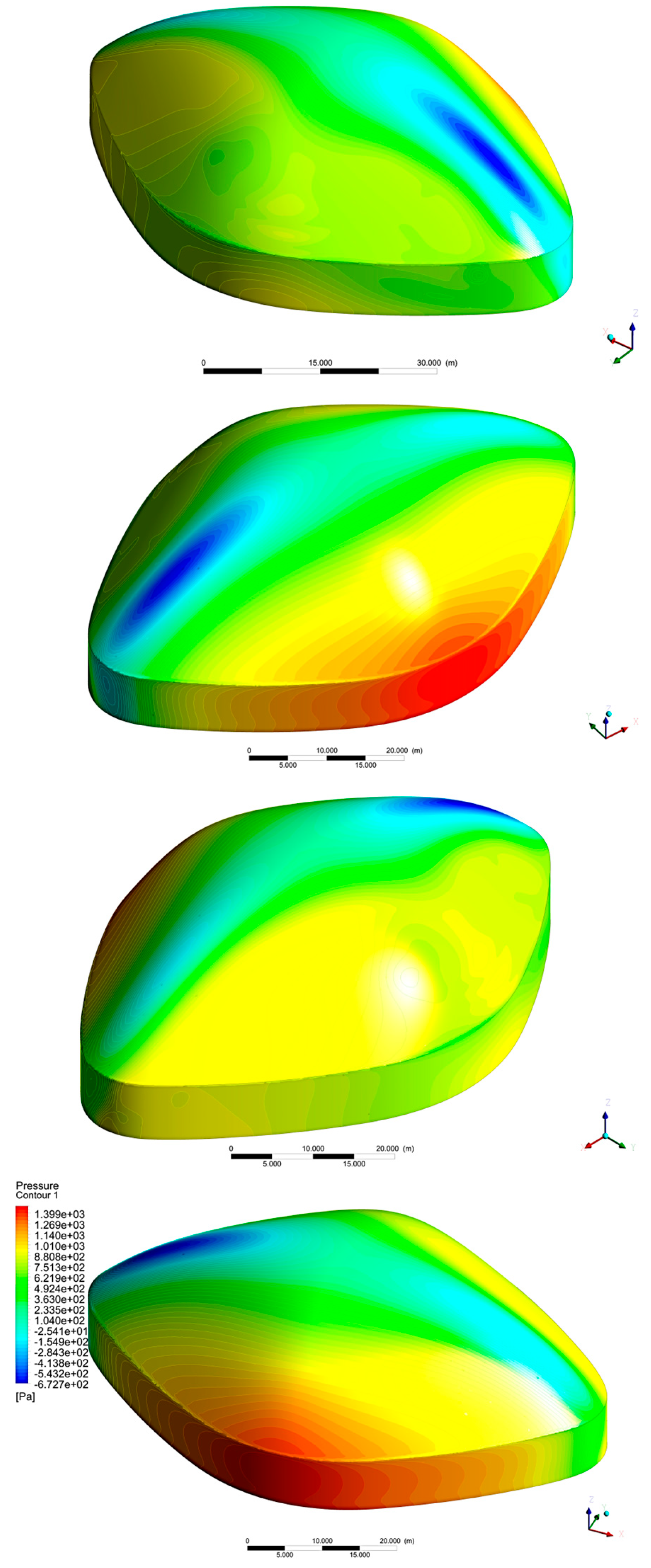
The results show large areas of high-pressure flow field on the stagnation side of the building, namely, the entire height of the two-story high façade and portions of the lower elevations of the ADSM. Integration of the pressure field on the body results in the drag force exerted on the entire MHU equal to 293 N, among which 74 N is exerted on the ADSM and the rest on the surrounding façades. As these values represent the pressure drag of the unit, the total of pressure and friction drag, namely, the total force exerted on the body, is calculated to be 304 N, which, for the individual case of the ADSM, turns out to be 84 N.
Figure 5 illustrates the pressure distribution over the MHU as the wind comes in contact and stagnates first through the façade and corners of the rhombus plan. It should also be noted that the wind conditions used for simulations, and therefore the loading conditions, are those of the worst-case scenarios known to happen on Mars. Given these worst-case scenarios, structural design and construction have been considered using an additional safety factor common in the construction codes. This will certainly cover the daily and annual alterations indirectly.

3.3. Seismic, Meteoroid, and Gravitational Impacts

Since the deployment of the seismometer SEIS of the InSight in February 2019 and March 2020, two distinctive types of Marsquakes have been detected. Of those 465 reported events, 424 are classified as high-frequency, with seismic energies around 2.4 Hz. Only 41 low-frequency events between 0.1 and 1 Hz have been detected, most of which do not have the S and P onsets as earthquakes; hence, they are relatively weak in comparison. Explaining the physical mechanisms of the Marsquakes and locating most of them is difficult due to their relatively small magnitude and having only one single recording station available on Mars. The S0173a and S0235b have been the only two Marsquakes with clear onsets and polarities that have been recorded so far [85].
Prediction and identification of the type, frequency of occurrence, and magnitude of Marsquakes in the construction site of MHUs in Valles Marineris are out of the scope of this paper, if not impossible, with the current documented data. For this reason, we assume the seismic episodes and their estimated periodic loads on the structure are irrelevant/negligible, given a reasonable safety factor in the simulation process.
In contrast to seismic forces on Mars, the impact of an asteroid and meteoroid showers is not negligible due to the tediousness of atmosphere on Mars. However, in this paper, the focus has been specifically on designing a structural solution that would withstand the constantly available static and dynamic loads on the surface under the assumption that no direct and destructive impact would crash the units. Hence, we assume a negligible meteoroid impact but suggest that constant observation and prediction of these events, as well as on-time evacuation, are necessary for crew safety.
Apart from the wind loads, another significant load that should be calculated in the simulations is the weight load, defined as the vertical force experienced by a mass because of its gravitation. The material, profile section, and mass of an element have a direct influence on the definition of this load in the simulation. As it has been mentioned before, the gravity on Mars is only 37.8% of that of the Earth, so the weight of each component on Mars is lower than its actual weight on Earth, and it is expected that the designed structure would be lighter in comparison to Earth. This has the advantage of lower compressive stress in comparison to the Earth and, of course, the more crucial tensile stresses due to the pressure difference explained in the sections above.

3.4. Structural System

3.4.1. Typology

As it was mentioned in the Introduction, there are several structural typologies that can be applied to the design of the MHUs. Due to previous investigations on the optimal method for construction in remote places, 3D-printed structural systems are expected to be the most suitable systems for construction on Mars. However, as this paper is based on a design in response to the pre-terraforming era on Mars, the capability of other structural systems, such as prefabricated components and concrete structures, should also be considered.
In the first step, based on the architectural plans and 3D model of a single MHU, a 3D structural model is proposed and modeled in Rhinoceros 7.00. The model contains horizontal and vertical structural components, which are located in places that were considered in the previous design.
The hexagonal modules are used for horizontal elements, which build an incorporated diaphragm for each floor. This approach also makes the 3D printing process easier and more consistent. In addition to that, corners of each interior garden are considered for the vertical structural elements (i.e., the small modules of green areas located inside the MHU interiors, cf. the semi-internal area around the core interior of MHUs, used for gardening and vegetation research. See [1].
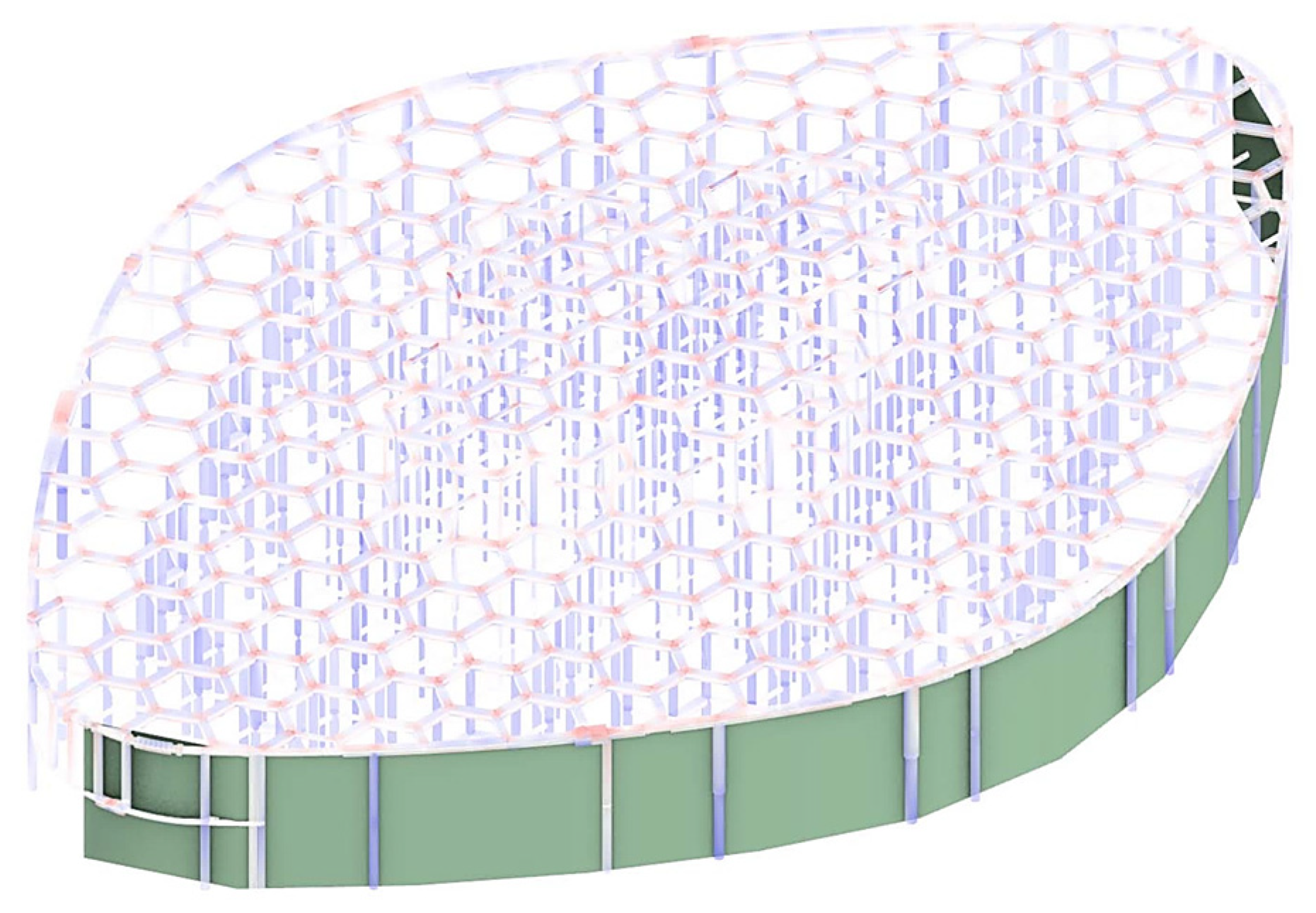
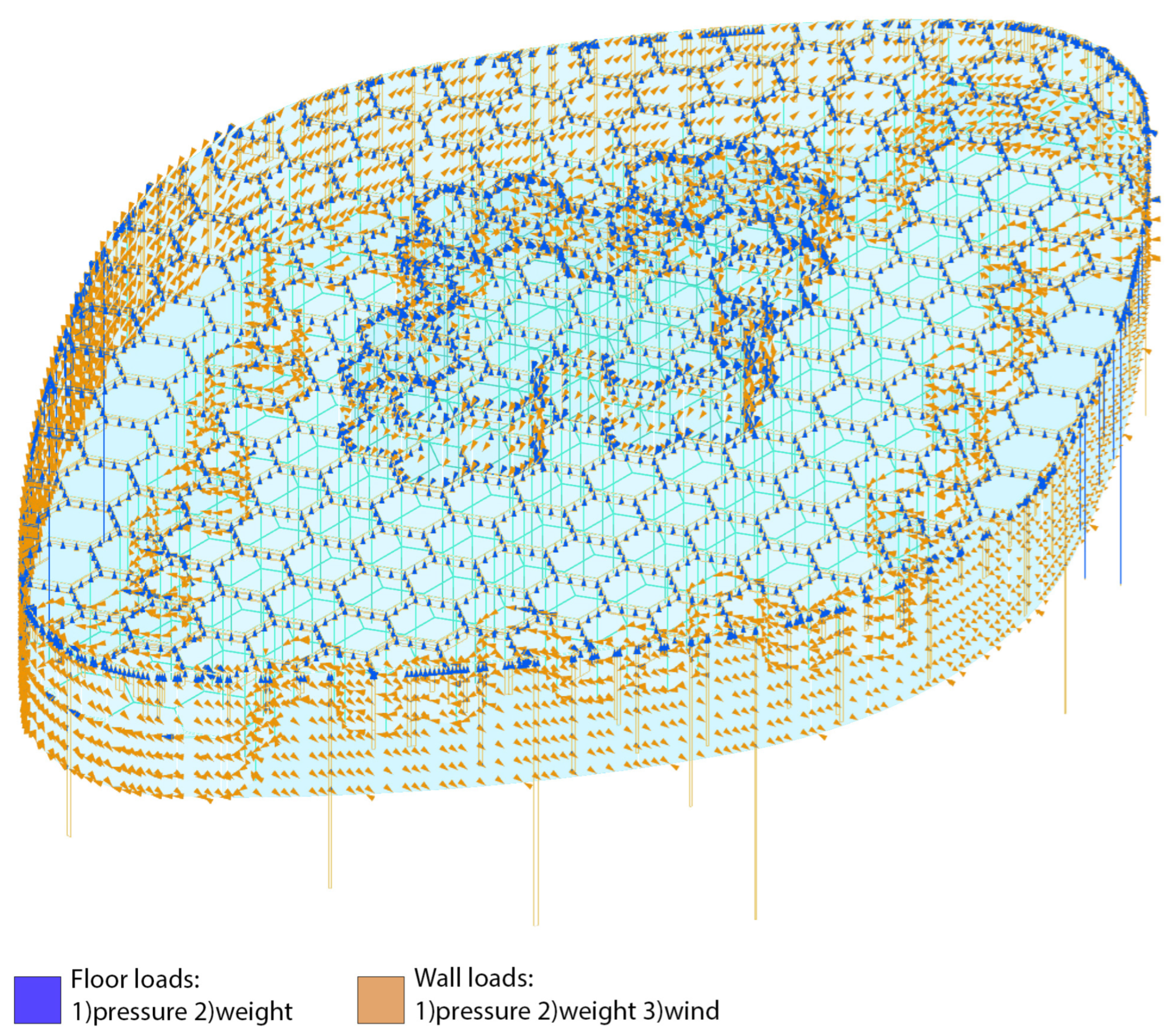
The proposed structure is designed to be a base model for starting Karamba-3D coding (i.e., a Grasshopper plug-in that uses FEM for structural analysis and optimization. See Section 4.3) and other structural calculations. The model will definitely be changed and optimized based on the simulation results in the upcoming sections. However, the base schematic 3D model, which is to be used in Karamba-3D calculations and simulations is based on the estimation shown in Figure 6.

3.4.2. Structural Components

Each structural system contains sub-categories known as components. Depending on the different structural types, these components vary. For instance, in a regular metal or concrete structural system, beams, columns, and foundation are the components. Main challenges related to structural components are usually the assembly, joints, and leakage prevention. In the case of designing a durable structure and construction plan for the conditions on Mars, it is necessary to choose the most efficient assembling method.
The designed structural system contains different structural elements, such as columns, beams, foundation, and building stories. In the first step, each story is divided into polygonal modular parts just like the first stages of the current design, with a structural beam as each side of the polygon. After modeling the beams, rectangular columns are also added to the model. For the beginning of the simulations, the square profiles are selected for the beams. Final results of the loads on vertical structural elements obtained through the above explained process are shown in Figure 7.

4. Structural Design

4.1. Building Model

The first step to design any structural system for the MHUs is to evaluate the lateral and dead loads on each component of the system. Therefore, in the beginning, a simplified 3D model of the project is developed so that the structural loads can be simulated by the software. By understanding the stress tensors exerted on the components, it is easier to obtain a corresponding design solution. This solution includes both system and material selection for the design. In this section, after a brief report on the simulation strategies, the modeling process and software will be discussed.

4.2. Structural Model

Selecting the best structural design method for the MHU project is a crucial stage that could affect massive challenges in the architectural design process and strategies. Generally, the designed structure must resist three different types of loads, namely, gravity, internal/external pressure difference, and wind. In order to recognize the stability and durability of the proposed structure, the Karamba-3D plug-in for Grasshopper is used for simulations.
Based on the 3D design, which was modeled in Rhinoceros 7.00 in [1], the proposed structural model is designed and formed. For that purpose, the building elements are designed in the Grasshopper plug-in in a polygonal modular algorithm, which was used in the architectural design steps. After that, all elements are optimized through simulations in Karamba-3D.
The first specific load calculated in the simulations is the weight load, which can be obtained by knowing the mass of the elements and Mars’ gravity. The material and profile section of each element have a direct effect on this load. Additionally, the internal/external pressure difference and wind loads are calculated based on the intermediary results reported in previous sections.
Based on the results from the deformation analysis, the optimization process will begin. To achieve final results with a stable structural configuration, five stages were considered. These stages are:
First analysis with custom setting;
Reshaping the cross-section of the axial component;
Adding structural role to exterior and garden space walls;
Dividing structural components based on their interaction with internal/external pressure;
Optimizing the range of cross-sections for structural components based on their utilization value (the ratio between von Mises stress and yield stress, which in the range above 100% shows structural instability).
After the first stage, the process includes two main factors, which are the buckling of the columns and the yield stress of the structural elements. In order to prevent buckling, different column profile alternatives are considered to achieve the best result. This also leads to a different profile dimension and material consumption. During next stage, because of the wide cantilevers (i.e., a single-sided extension of the floor with no bearing columns on the free side) on two sides of the structure on the first-floor and also to prevent the stress from reaching the yielding point (the threshold stress for the material to undergo plastic deformation), some parts of the exterior envelope must support the weight loads.
In the third stage, due to intense internal/external pressure, structural components are classified based on their interaction with this pressure.
In the final stage for optimizing the dimensions for each building component, they will be divided into separate groups based on their different levels of bearing loads. The divisions are set by Karamba-3D optimization, which selects optimal cross-sections for beams and shells in the model according to EC3 (EN 1993-1-1 [86]), which applies to the Eurocode design of buildings and other civil engineering works in steel, as a default setting for non-specified materials of structure. This method also reduces the percentage of utilization. Utilization of elements in the Grasshopper software 1.0 (not to be mistaken with the structural components) is to obtain the required level of utilization for each element.
The combination of the acting forces on a structural component will lead to net axial compression or tension [87], resulting in normal stresses in a principal axis direction, when a point-load is exerted on the centroid of the component cross-section.
In structural analysis, the total axial stress is the combination of bending and axial compression (or tension). It is important to understand the difference between displacement and deflection. The deflection is the furthest distance from the original position of a structural member before the load is applied to its last location after the application point. It is thereby the distance of the permanently deformed most point of a member to the projected point, after the elimination of the load. The displacement is the distance from the original position of the structural joints before the exertion of the load to their final position after the application of the load, leading to the deformation of the structure.
A brief overview of the underlying theories of the finite element method (FEM) used for the numerical analyses is provided in Appendix C.
In addition to the mentioned structural components, the foundation of the MHU is also modeled and analyzed. There are three main factors related to the material of the 3D-printed foundations, which are used in Karamba-3D simulations, including bearing capacity, density, and the angle of repose of regolith soil. After that, the shape and dimensions of the foundation are calculated through two different methods. For each column, an isolated foundation is considered. This is followed by the determination of the element geometry based on the simulations so that the experienced pressure does not exceed the maximum bearing pressure of the Martian soil.

4.3. Simulation Specifications

As mentioned before, this work utilizes the Karamba-3D plug-in in Grasshopper, which uses FEM for structural analysis and optimization for a variety of set objectives. It is developed to be undemanding and to give an early understanding of structural responses with a seamless connection between geometry and analysis. Each change in geometry will result in a live response in the analyses, compared to a conventional analysis process, which is usually conducted for a certain state. The short computing time of Karamba-3D makes it possible to explore geometries both manually and in conjunction with optimization tools [87].
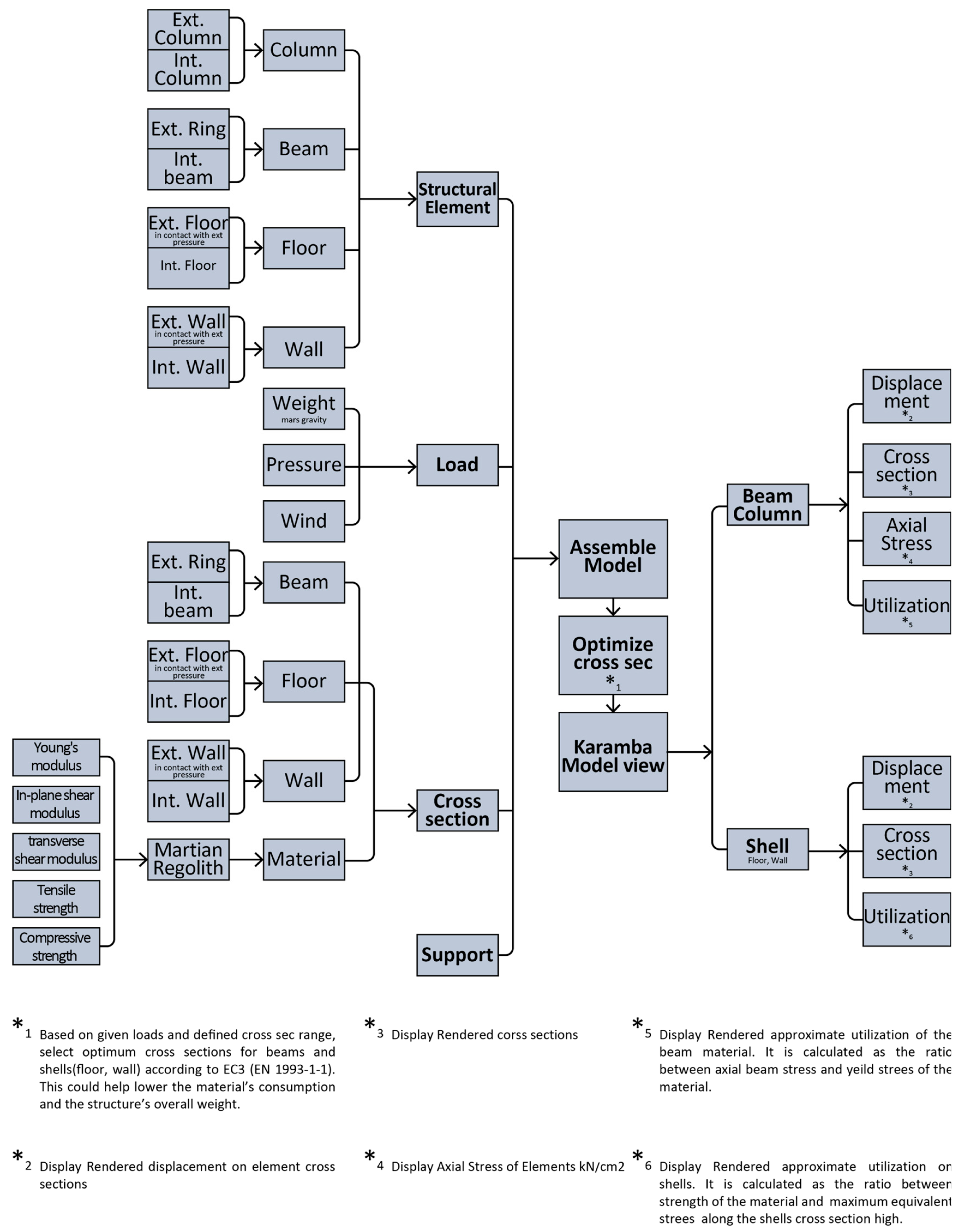
Beam elements are defined according to the elastic beam theory, i.e., Bernoulli beams, in this software. These adjacent elements are dependent on each other by sharing one or several nodes. Each of these nodes consists of six degrees of freedom (DoF), enabling movement and rotation in every direction [87]. The simulation process of the MHU structural analyses is shown in Figure 8. The simulation process in the Karamba-3D plug-in contains three main stages:
  • Inputs, which include creating the structural model, model discretization, defining material properties, loads, and boundary conditions;
  • Optimizing the cross-sections;
  • Analyses and results obtained from Karamba-3D.
The first step for analyzing the structure is to transform the 3D structure developed in the Grasshopper to structural components of Karamba-3D. A collection of inputs is gathered with the Karamba-3D model assembling components. To create these components, it is necessary to have the required inputs, including structural elements, their cross-sections and material, supports, and loads.
Structural elements consist of columns, beams, floors, and walls. Each of the mentioned elements is sub-categorized into two groups based on the different types of loads they are subjected to. The first group, which is shown in Figure 8 and denoted by the EXT prefix, is reserved for those in direct contact with major pressure differences. The second group, which is shown in Figure 8 with the INT prefix, is the one that resists minor pressure differences.
Supports contain columns and bearing wall joints to the foundation. They are considered moment connections (i.e., rigid), meaning the reaction forces and moment in principal axes are non-zero.
The loads that affect the structure are weight loads, wind loads, and internal/external pressure differences. Weight loads in Karamba-3D are considered the total weight. This is calculated by applying a unit vector (0,0, −1), considering the total weight of the structure. It is to be noted that this ansatz is based on Earth’s acceleration of gravity and is a preset parameter in the Karamba-3D. In order to match the Martian gravitational constant, the said unit vector is adopted (0, 0, −0.38) to capture the gm = 3.721 value.
For calculating internal/external pressure differences, first, we consider the different pressure magnitudes between interior spaces and garden areas. Accordingly, the following categories could be defined (Figure 9):
  • First group: elements that are located between the interior spaces of the MHU and the garden areas;
  • Second group: elements that are located between the garden area and exterior;
  • Third group: elements that are located between the interior and the exterior area of the MHU.
According to this division, we start the simulations with basic parameters and calculate the pressure each wall and floor is subjected to by the internal/external pressure calculation (Table 2).
Table 2. The amount of pressure experienced by the building envelope elements of a single MHU *.
Walls and RoofsGarden-ExteriorGarden-InteriorIn/Exterior
P (%atm)74%25%99%
P (kN/m2)74.980525.33125100.312
* Pinterior = 100% atm; * Pgarden = 75% atm; * Pexterior(mars) = 1% atm.
Figure 8. General overview of the simulation and structural analysis using Karamba-3D. The diagram indicates the process used to model and analyze a single MHU structural model. The process starts with modeling structural elements and gathering input data for loads, cross-sections, and supports, which then results in the assembled model. The created model provides structural data needed for optimizing the structural design. In the case of wind loads, one should consider the possibility of a breeze in any direction. For the structural simulation in Karamba-3D, the wind direction is assumed to be perpendicular to the main axis of the MHU plan, as the maximized projected area leads to the highest wind pressure differences, which is considered the basis for the worst-case-scenario for the current design (Figure 10 and Figure 11).
Aerospace 12 00761 g008
Primary wind pressure on the Mars atmosphere is calculated to be 0.00542 kN/m2. On the other hand, the area of the east side of MHU (723.6 m2) has been used to define a wind load equivalent of 3.90745 kN. Table 3 summarizes the cross-sectional properties of the structural elements with respect to the loading regimes.
For material specifications, processed regolith and sintered basalt are used with the following mechanical properties:
  • Young’s modulus = 73,000 MPa
  • Tensile strength = 14 MPa
  • Compressive strength = 490 MPa
As for the case of the shear modulus, for which there are no recorded parameters (see Table 1), based on the previous research, Karamba-3D’s material limitation is considered to be between 0.33 and 0.5 of the Young’s modulus E. The range of the shear modulus G was calculated to be between 2433.34 and 3650 kN/cm2. The minimum value of 2434.35 kN/cm2 is used as the shear modulus in the structural simulation.
By finalizing the calculation of the inputs, the process of assembling the model is started, and structural simulations are run to generate the outputs. This is an iterative process, in which the structural design of the subset elements and their properties, as well as the total resistance of the structure, are updated. This process results in an optimal material usage by the means of a global optimization in the displacement of the structure, as well as its total weight.
Furthermore, the cross-section optimization component is used to reach the smallest cross-section of the structural elements and also to prevent them from reaching the thresholding yield stress, as well as to minimize their displacement. The cross-section optimization is based on the maximum stress in the elements. The maximum stress is calculated from the sum of compression and bending stresses shown in Equations (9) and (10) [88].
σ t o t a l = σ c o m p r e s s i o n + σ b e n d i n g
N A + M W = N b · z + M   b · h 2
By finalizing the calculation of the inputs, the first stage of the process of assembling the model is started, and structural simulations are run to generate the outputs. In the first stage, the designed rectangular-shaped cross-sections (in previous research) were used with these specifications:
Figure 9. Structural elements classified by various internal/external pressures.
Aerospace 12 00761 g009
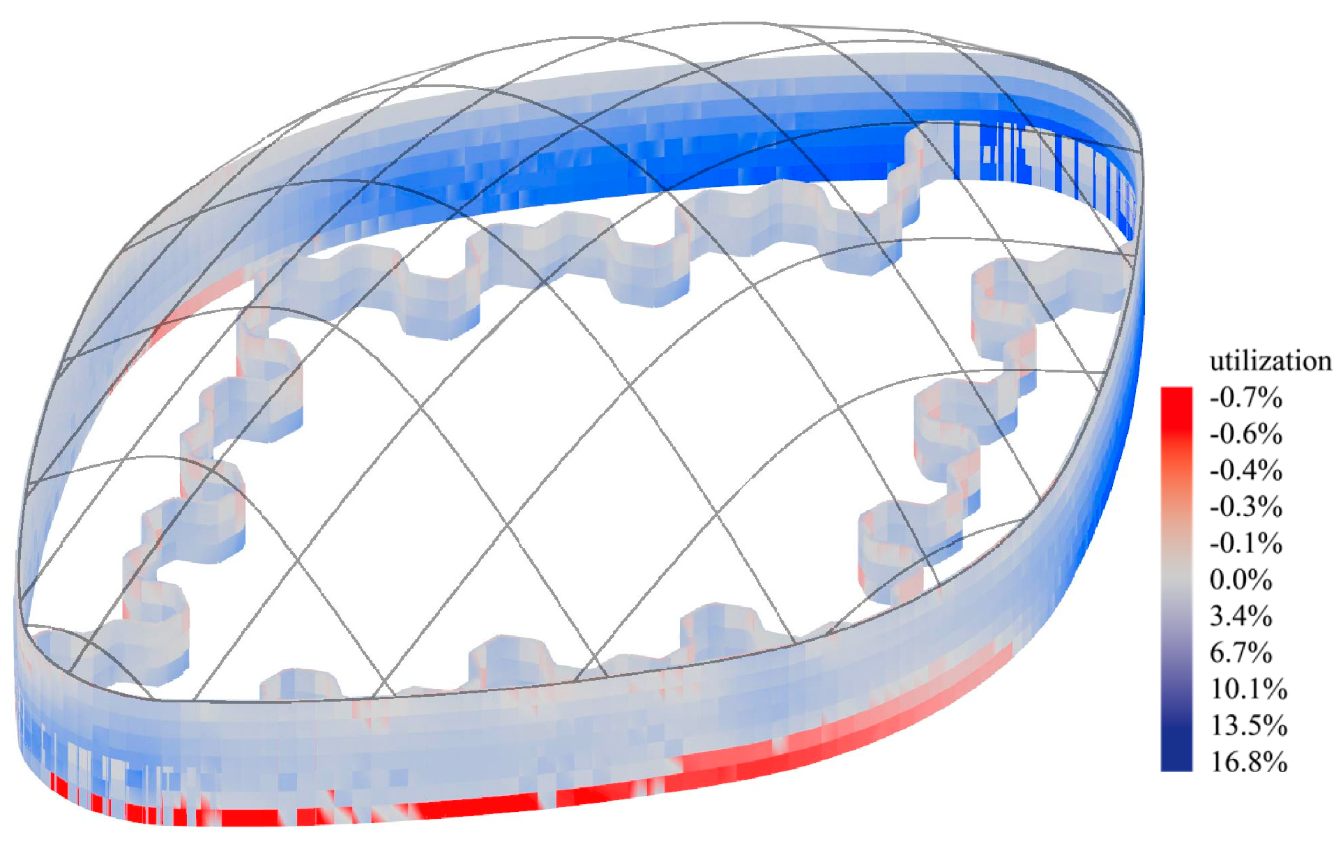
Figure 10. The utilization rate of vertical surfaces based on the pressure difference between (i) the outside and the garden and (ii) the garden and the inside spaces.
Aerospace 12 00761 g010
Figure 11. The bird-eye view of the longer façade of the MHU, showing the exterior surface in green facing the highest wind loads.
Aerospace 12 00761 g011
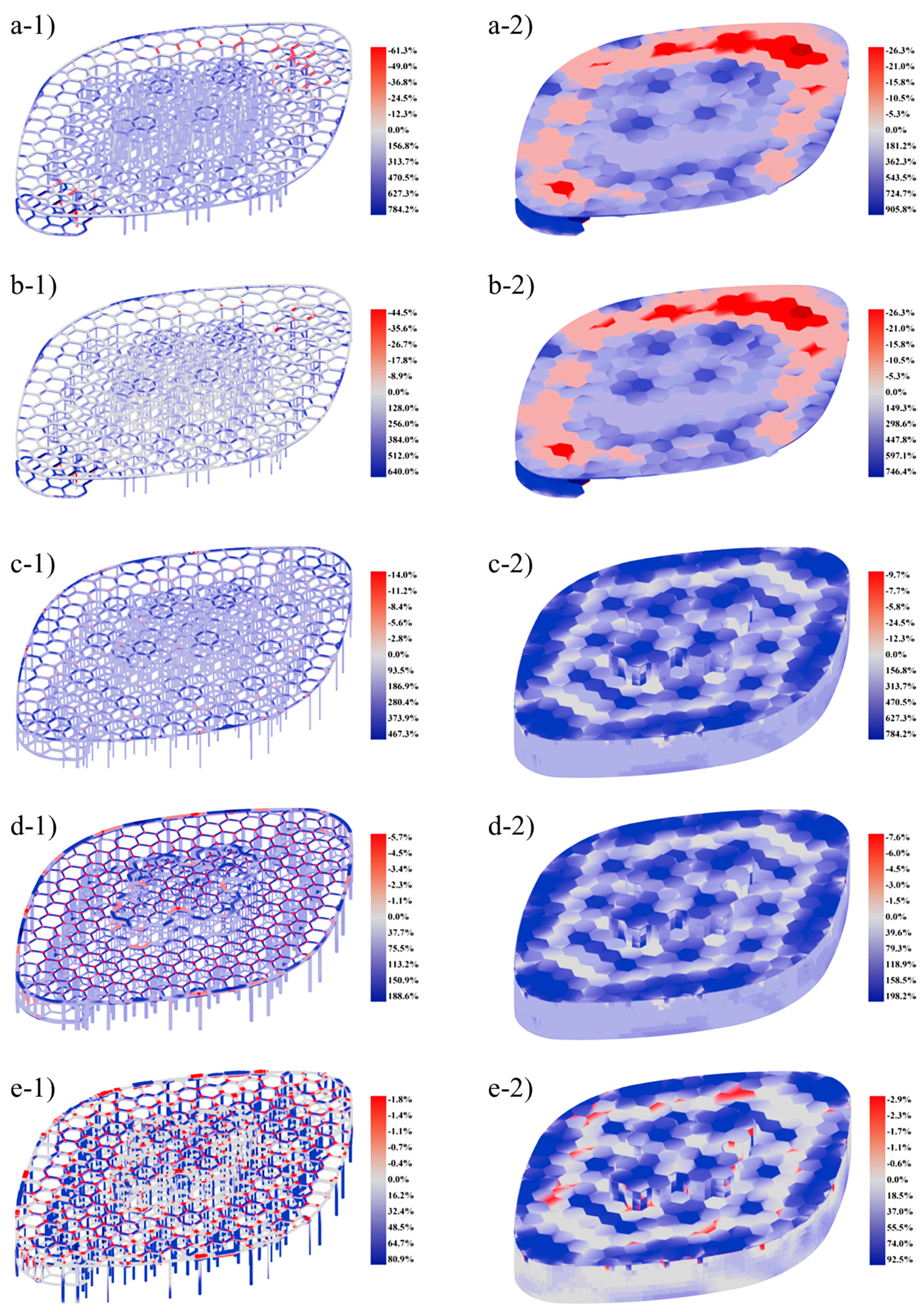
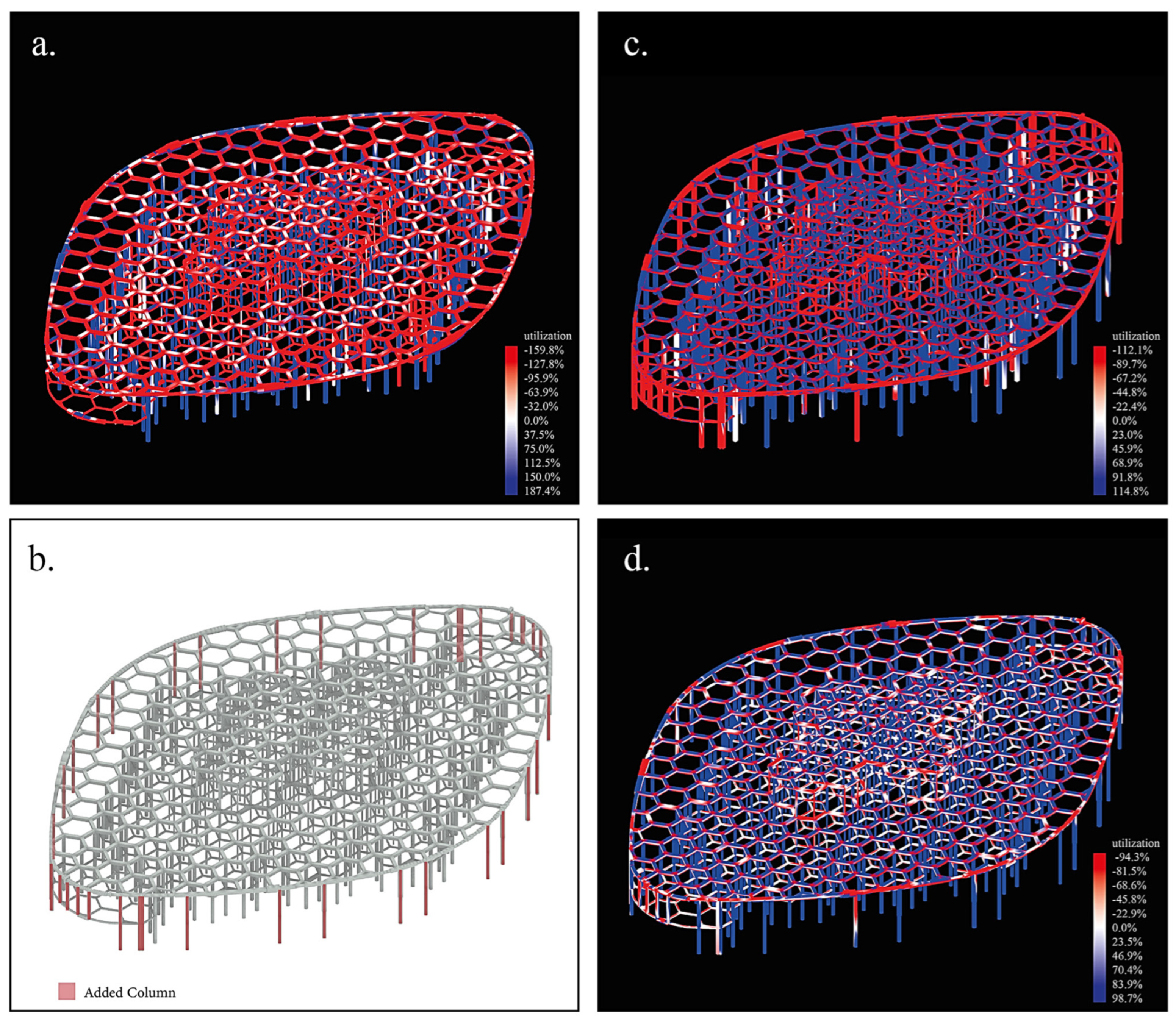
The first stage structural analysis was simulated with rectangular-shaped cross-sections for both beams and columns. (Figure 12) The result shows mainly the tensile stress in the structural element as it overpasses the yield stress, which can be seen in the utilization rate.
In order to offer a uniform load in vertical elements, circular columns are used for the second stage. Based on Figure 12, it can be seen that both tension and pressure are reduced by using a circular-shaped cross-section. This is a result of a better response to axial stress in columns to reduce torsion or buckling in these elements.
Using circular cross-section for columns also leads to a lower profile dimension and material consumption. As the simulation proceeds, to better stabilize the structure and achieve a utilization rate below 100%, exterior shells between the garden zone are added as structural elements to support weight loads, and the structural resistance toward internal/external pressure is improved, which causes an excessive tensile stress in the structure. The third stage corresponds to a better solution because of the wide cantilevers on two sides of the structure on the first floor; it also prevents the stress from reaching the yielding point.
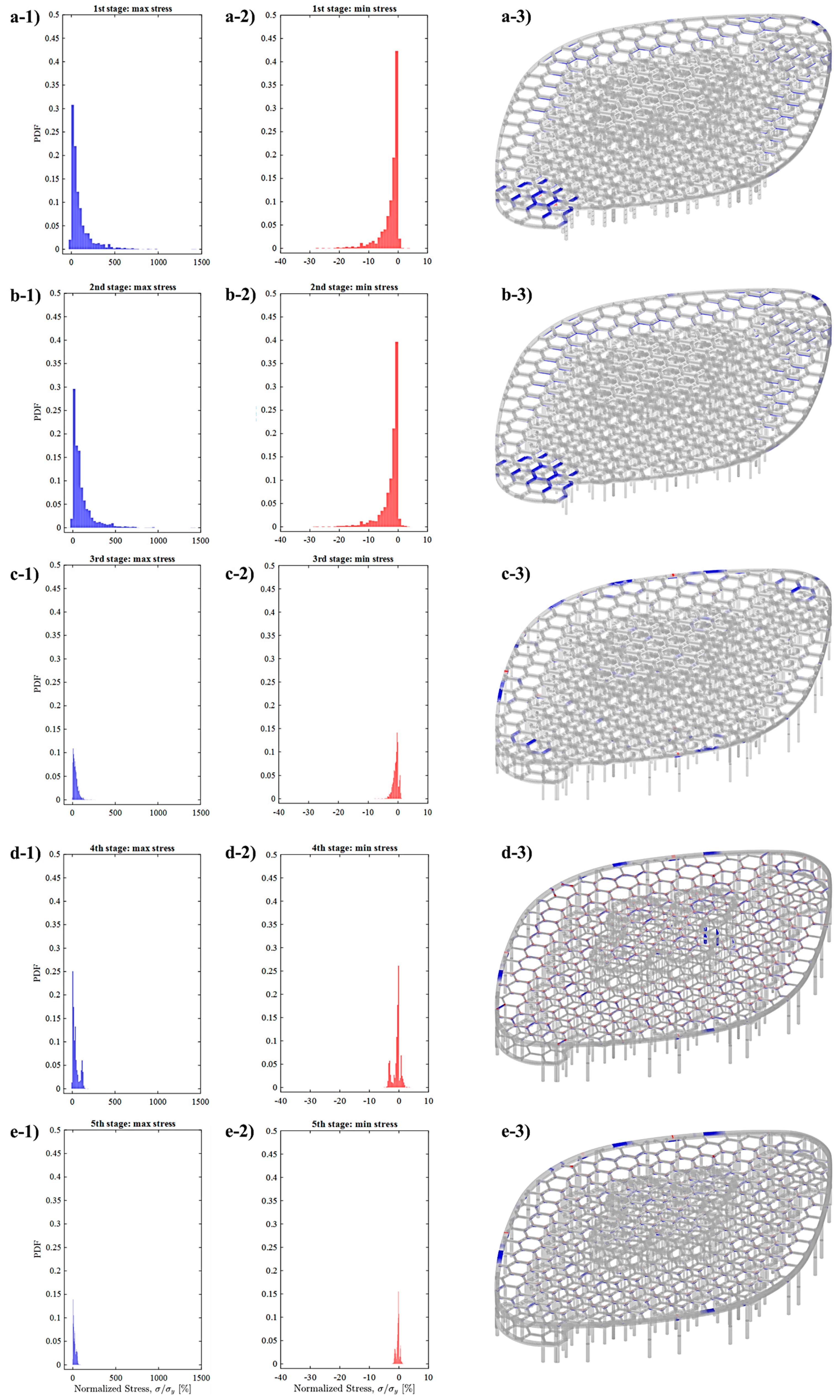
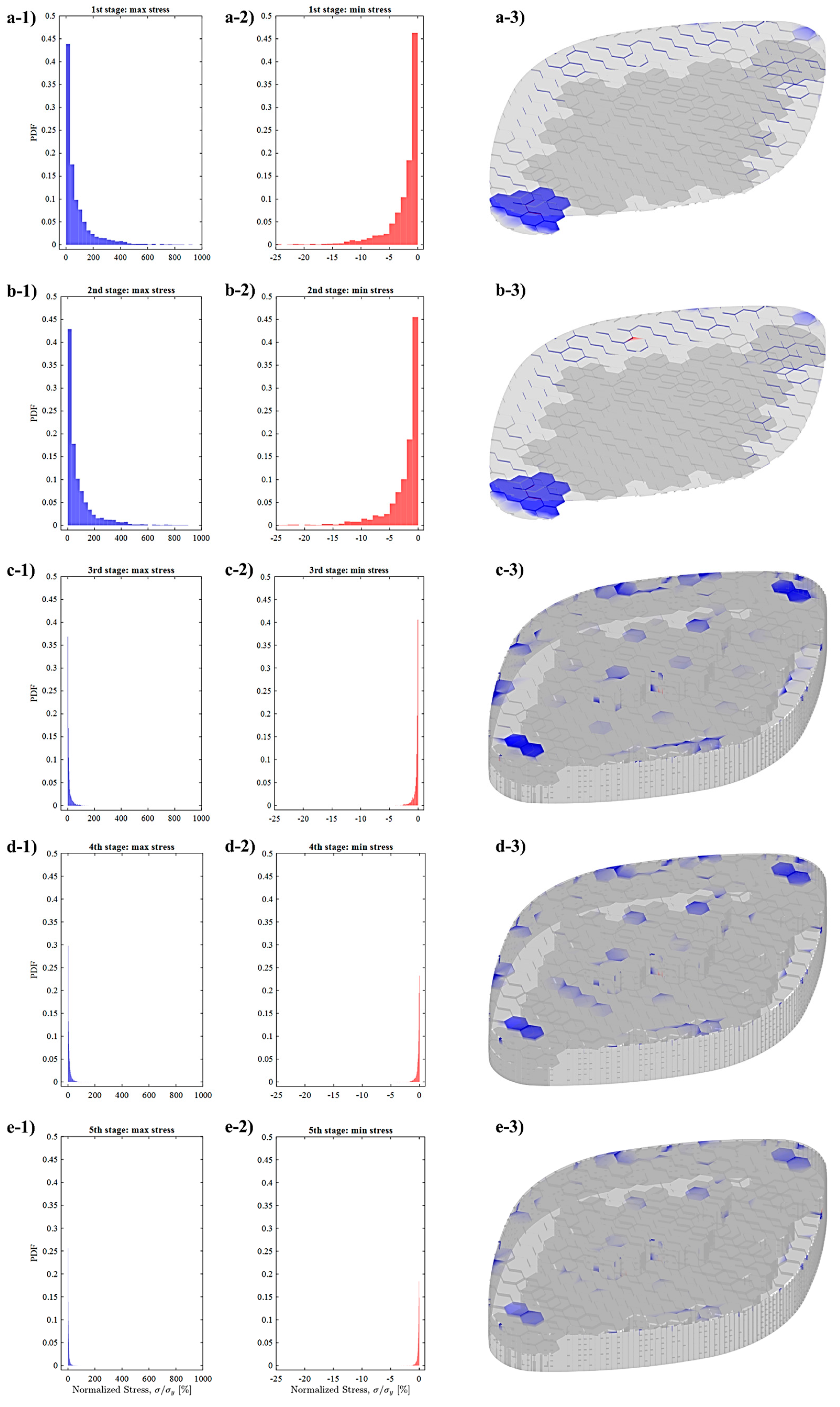
After the third stage, it can be seen that compressive stress is under control and tensile stress is significantly reduced (i.e., 30.95% to 3.17% reduction in the number of linear structural components surpassing the yield stress threshold, moving from stage 2 to 3, and 27% to 0.25% reduction for the same criterion in the shell-type components), although it does not reach the stabilized value. Based on the last simulation, it can be understood that tensile stress has a higher value on exterior ring beams and on parts that are directly in contact with the exterior/interior force. Therefore, the fourth stage starts with varying the structural input for three groups of structural elements mentioned in previous sections based on their juxtaposition to internal/external pressure. At this stage, the utilization rate reaches near the desired response.
At the fifth stage, the optimization feature in Karamba3D is used to optimize cross-section usage. A range of cross-sections with higher values to lower values from previous stages is used as inputs. A range of cross-section dimensions is assigned for structural elements that are divided into separate groups based on their different levels of bearing loads, as mentioned for the previous stage. The divisions are set by Karamba optimization, which selects optimal cross-sections for beams and shells in the model according to EC3 (EN 1993-1-1).
Table 4 summarizes the last stage’s cross-sectional properties of the structural elements with respect to the process developed.

5. Results and Discussions

The structural analysis of the MHU is a crucial aspect of designing safe and sustainable living spaces for future human missions to Mars. As we continue to explore and learn more about the planet, it is essential that we prioritize the development of innovative and efficient building techniques that can withstand the harsh Martian environment. In this study, different simulations of structures with varying dimensions are analyzed and reported, culminating in the identification of the optimal configuration regarding the architectural design. This section presents core findings of the structural analysis in terms of:
Categorization of the different structural elements based on their load-bearing conditions (the exerted pressures, among other parameters discussed in the previous sections);
Consideration of possible choices for the geometry of the members (i.e., cross-sectional types, etc.);
Sweeping a range of dimensions for the said geometries to obtain the optimal shape and sizes for the final chosen design);
Modification of the design by adding/subtracting members to fulfil the lacking capabilities of the design; the addition of a set of load-bearing exterior envelopes to maintain the structural integrity of the MHU in response to the previously mentioned pressurized-vessel layout.
It is needless to say that all the abovementioned steps have been carried out under the assumptions and constraints given by the 3D printing technology and the available in situ resources. The seamless integration of beams and columns in construction has been made possible through the advent of 3D printing technologies, which, on a more technical level, leads to the use of moment-bearing connections between structural members.
Furthermore, the structural design is aimed at matching the architectural plan as much as possible while ensuring that the structure assembly is effortless, more so as the construction is to be carried out on Mars. The cross-sections and thicknesses of the structure are also considered to resist internal/external pressures from different sources. When it comes to the resistance against internal/external pressure, most considerations in this article tend to focus mainly on the structural aspects of the MHU. However, there are other techniques that can be employed in layering the walls of a space unit to reduce the impact of the internal/external pressure. Therefore, further study is necessary to fully understand the effects of these techniques and to ensure that they are applied in a manner that enhances the overall integrity of the space unit.

5.1. Structural Configuration

To facilitate comprehension of the structure, system inputs were divided into linear elements, such as beams and columns, and surface elements, such as walls and floors.
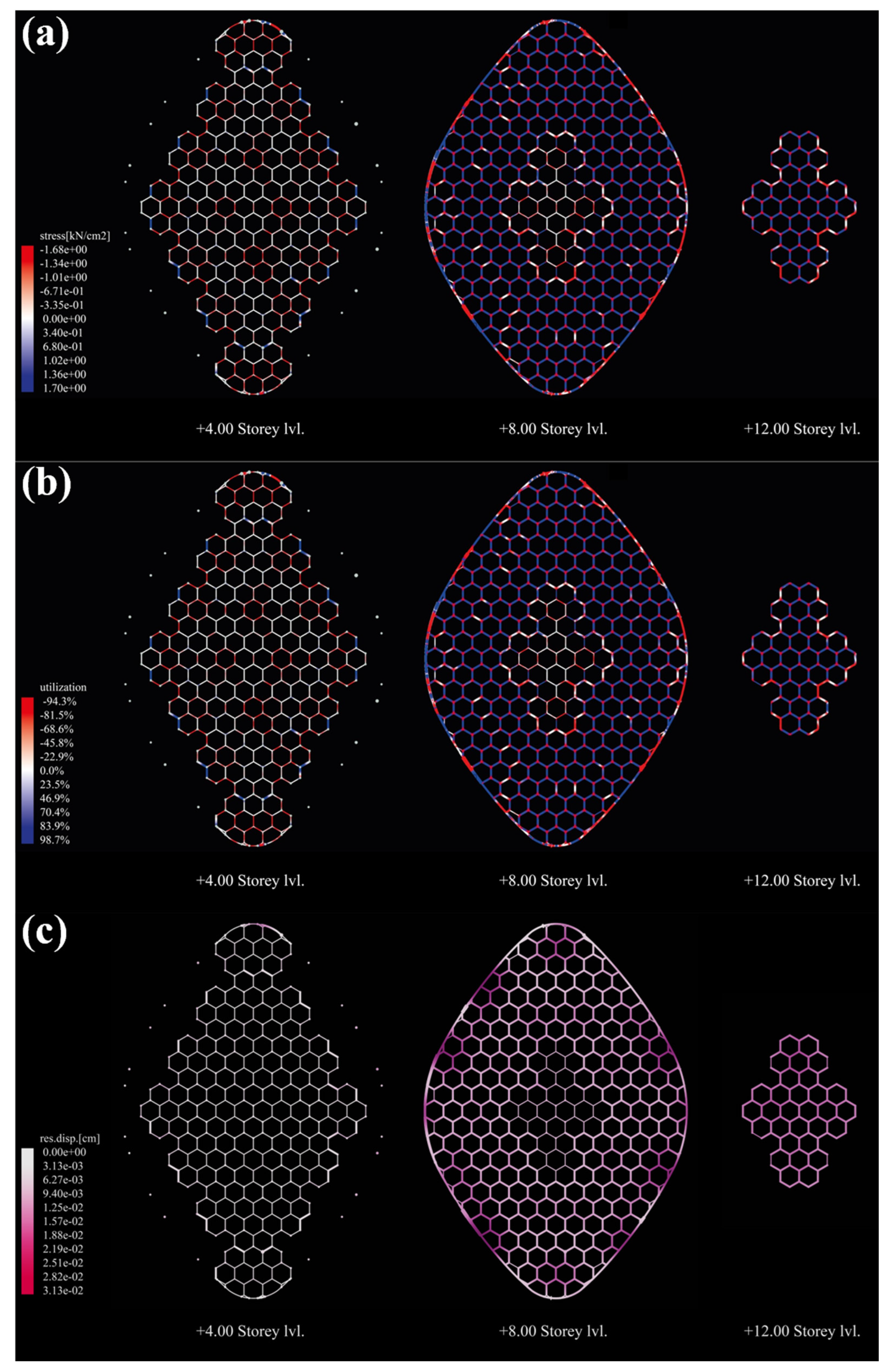
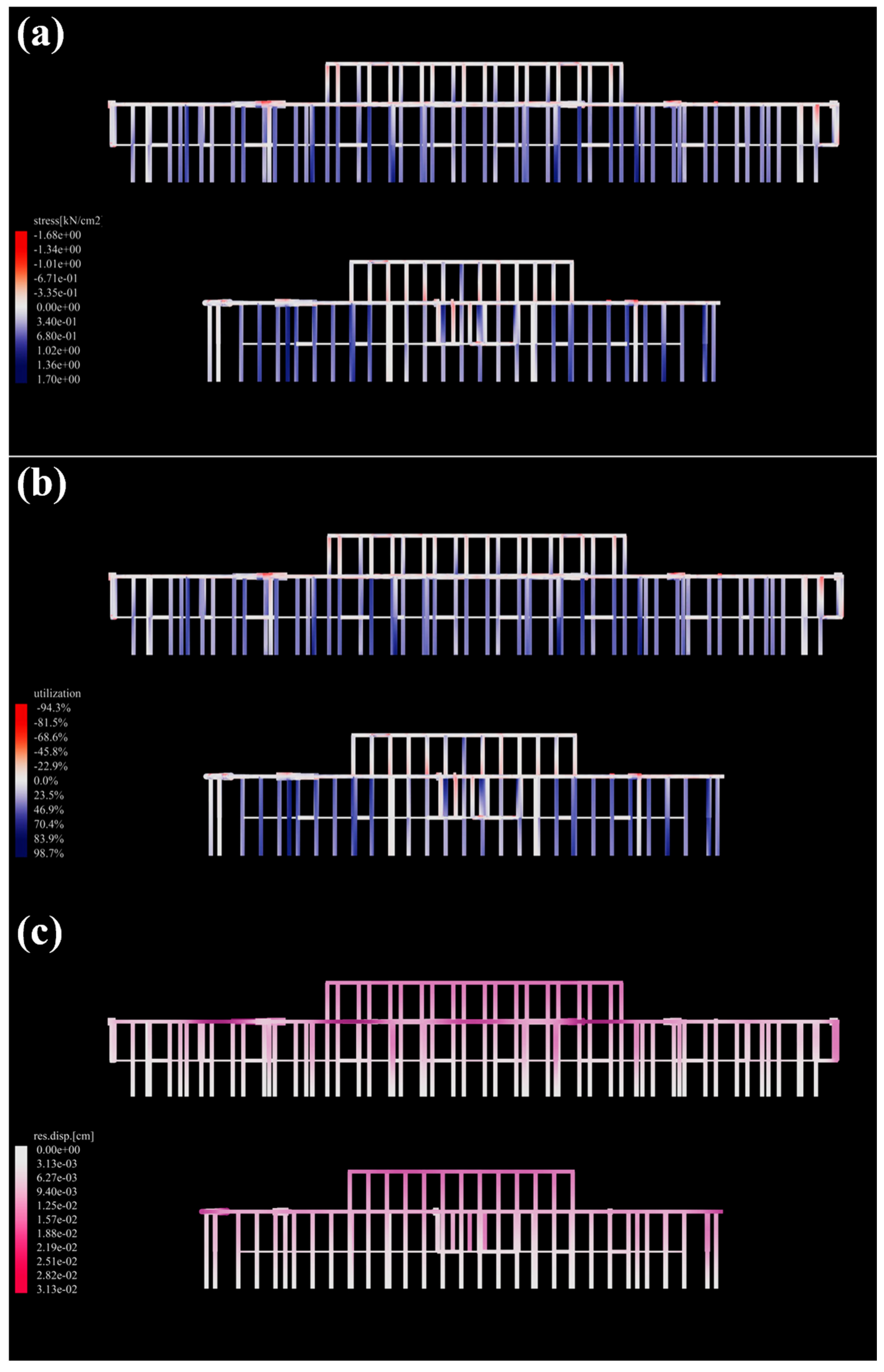
Moreover, to enhance the visualization of element reactions, all structures were depicted in three modes, representing utilization, stress, and displacement.
Upon conducting a thorough structural analysis of the MHU, a range of goals with the overarching aim of improving the overall effectiveness, efficiency, and sustainability of the unit was determined. The authors are aware of the complexity of the definition of concepts such as sustainability for the context of the mission at hand; however, the term is mainly targeted at in situ materials, minimal human interaction in construction, and optimized material use.
In general, it has been determined that despite the fact that the gravity on Mars is about 38% of that of the Earth, the excessive pressure gradients present between the interior and exterior of the units on Mars lead to an increase in the demanded structural member strength for such designs. In the context of this article, this heightened strength has been achieved by enhancing the geometric and dimensional optimization of the structural members.
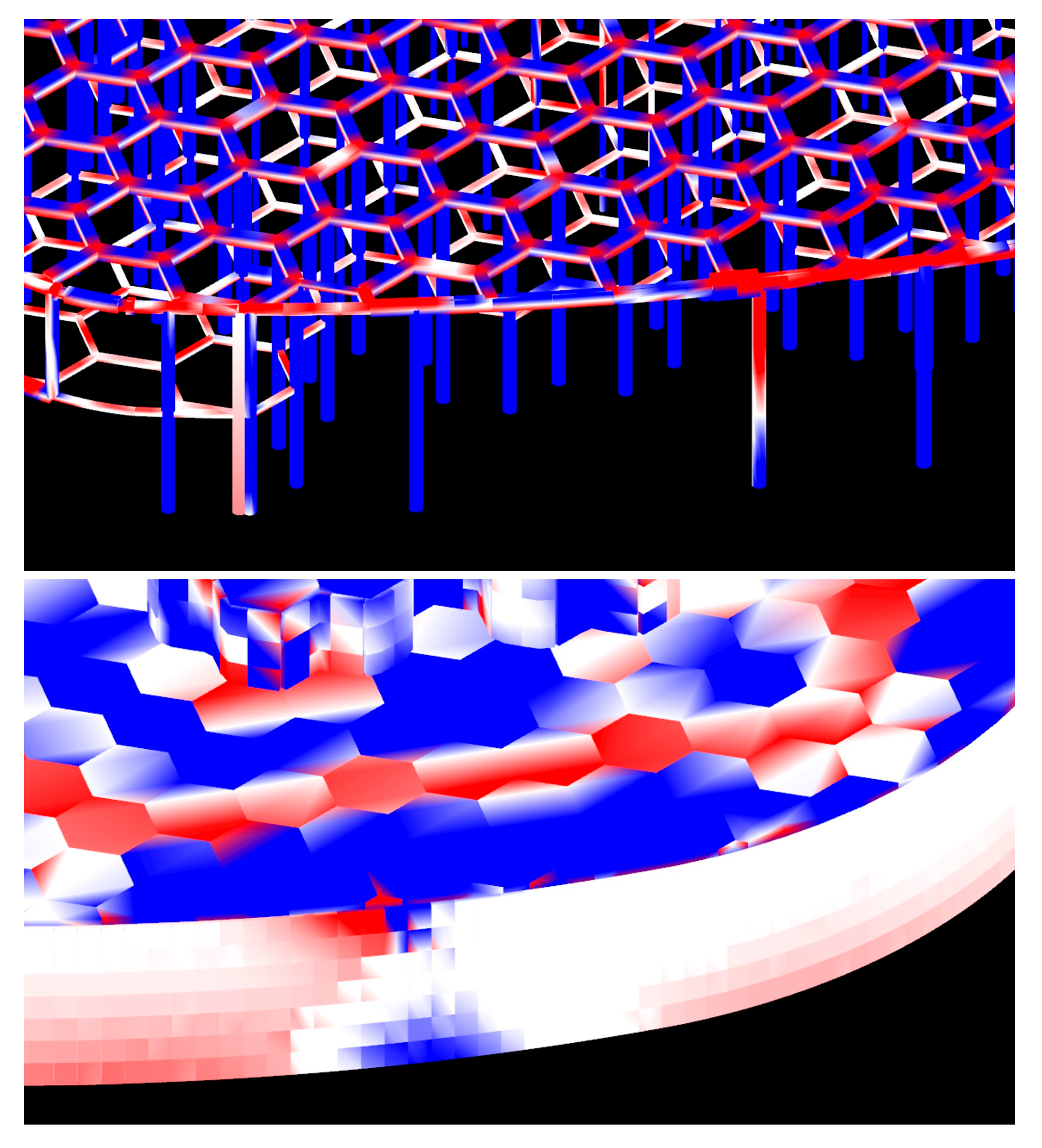
A significant finding was that due to the considerable amount of pressure exerted on the unit, it is imperative for the majority of components to withstand the tensional forces, as the higher number of such members is observed in Figure 13. Drawing from the fundamental configuration of the MHU, there are certain structural components that exhibit a remarkable level of resilience against the intense compression, which are highlighted by a distinct red color. The structure as a whole can endure higher levels of tension. However, it is crucial to opt for materials that possess the capability to cope with both compressive and tensile stress.
As mentioned before, a range of iterative simulations during five main stages was conducted in order to attain the most favorable structural configuration (i.e., optimized material use while maintaining the maximal structural efficiency), and a number of structural modifications were selected through the analysis process (Figure 14). The scope of these modifications is aligned with the objective of preserving the optimal living space within the MHU, as mentioned in the previous section. Based on the aforementioned categories, the result with total displacement of 0.02 cm under different loads was obtained according to these five stages of analysis, and the process of reducing the utilization rate in each stage was obtained as follows:
As can be seen, the tensile stress can be disregarded, and the compressive stress is inhibitable. To stabilize the structure and not to surpass yield stress, changing rectangular cross-section columns to circular ones reduces the whole structural utilization by 18% for both linear and shell structural components. The next stage, which is adding exterior walls’ structural role, reduces the tensile utilization by 1149% for linear components and by 839.84% for shell components. Division of structural components based on their interaction with internal/external pressure has a 81.49% reduction in maximum tensile utilization for linear and a 14% for shell components, while the last optimization for the cross-section leads to a reduction in the maximum tensile utilization of linear components by 182.76% and 74.1% for shell components, to finally stabilize the structure.
Based on different iterative processes, the final three stages were shown to have the most significant role in reducing stress in the linear component, which shows the importance of internal/external pressure impact and the fact that the columns have a tying-up role in keeping the structure. Also, maximizing the cross-section range for components under major stress and giving the exterior walls structural roles have the strongest impact on reducing shell stress, which is seen in the cantilever part of floors restrained by having exterior walls as a shared structural component. Such a dramatic decrease underscores the importance of considering how the cantilever parts affect the structural element under different loadings. Moreover, when categorizing structural components based on their interaction with internal/external pressures, we observed a significant reduction in maximum tensile utilization: 81.49% for linear components and 14% for shell components. This division highlights the critical role that internal/external pressure plays in the overall stability of the habitat unit.
The analysis reveals that the process of three-group-division structural components, followed by the addition of cross-section range and optimization of the dimension of each components’ stress, significantly influences the reduction in stress within linear components and allows for stabilizing the whole structure and reducing the maximum tensile utilization by 94.11% for linear and by 74.10% for shell components at the final stage compared to the previous stage. This finding emphasizes the importance of the impact of internal/external pressures on structural integrity. Additionally, it becomes clear that the columns play a vital role in maintaining the structural cohesion of the MHUs and act as a cable sustaining the structure under tensile stress.
Furthermore, maximizing the cross-sectional range of area of components subjected to significant stress, paired with the addition of exterior walls as integral structural elements, (which tensile utilization reduction for stage (3) shows 1149% in linear- and 839.84% in shell components, which for stage (5) is 182% in linear- and 74% in shell components) has the most pronounced effect on decreasing shell stress. This observation indicates that the cantilever sections of the floors benefit substantially from the reinforcement provided by exterior walls, as well as the internal/external pressure controlled by the optimization of the cross-section and the use of maximum element dimensions for the most stressed parts acting as shared structural components, enhancing the overall stability and resilience of the MHUs.
The structural analysis of the MHUs was conducted using the Karamba 3D plug-in in Grasshopper, with the probability distribution functions (PDF) of the obtained loads presented in a series of histograms (Figure 15 and Figure 16). The analysis was performed in several iterative stages, each focusing on specific design aspects and their impact on the overall structural performance.
The initial analysis revealed a concerning trend in the structural members. A large number of the linear elements (i.e., beams and columns) were subjected to relatively low axial stresses, while a significant portion, 29%, of linear elements (i.e., 892 members) had reached the tensile failure state, particularly around the cantilever regions on the first floor. This unbalanced stress distribution indicated that the initial design was not adequately addressing the structural challenges posed by the Martian environment, with a maximum tensile utilization value of 1432%. A similar pattern was observed in the shell elements (i.e., walls and floors), where 1357 (equal 59%) members reached their yield strength, with a maximum utilization rate of 902%. The high stress concentrations in the cantilever regions, especially at the top of the north side and the lower parts of the south side of the MHU plan, suggested significant bending and torsional forces acting on the structure.
At the second stage, where the column cross-sections were modified to circular shapes in order to mitigate the effects of buckling and torsion, the number of failed members under tension decreased slightly, but the maximum tensile stress and the probability of inefficient structural cooperation were still relatively high. For shell elements, however, this stage focused on linear elements and their cross-sections. This, however, shows a decrease in the number of members without active load-bearing roles, indicating that the improved cross-sections of the linear elements had a positive impact on the overall structural efficiency, and at the joints where the floor load is transferred through columns, it indicates better results and the decreased maximum utilization value for tensile stress to 891%.
The third stage introduced the structural walls, including the perimeter walls and internal partitions, as part of the analysis. The inclusion of these wall elements had a noticeable impact on the stress distribution. For the linear elements, the number of members that reached their yield strength decreased to 99, and the maximum utilization value reduced to 264%. A similar trend was observed in the shell elements, where the number of members that passed their yield strength decreased to 23, and the maximum tension value reduced to 151%. The addition of the exterior walls helped the unity of structure to minimize the accumulation of stress in just cantilever parts and showed that adding exterior walls helped better distribute the load, especially from the first floor. This also decreased the torsion and bending. The previous stage showed massive tension in the top part of the north and lower parts of the south cantilevers and the reduced concentration of stress in the structure, especially in cantilevers, and it showed more balancing behavior in the PDF of elements.
At the fourth stage, the analysis revealed an increase in the number of failed elements under tension, but the maximum tensile stress was reduced to 182%. Interestingly, the members under tension with the utilization value in the range of 50% to 100% had a less promising structural role, while those between 100% and 150% experienced more failures. Although the cantilever parts act in the most balanced way compared to the previous stages, this highlighted the need for a more targeted approach to address the stress distribution across different zones of the structure. For shell elements, the result is much more efficient as the number of elements that have passed the yield stress decreased to 12. Because of cantilever parts, the probability of elements hardly reaches a straight balanced line.
The final stage of the analysis involved the use of the optimization component in Karamba-3D to determine an optimal range of cross-sections for the structural members. By assigning smaller cross-sections to members under lower stress and larger cross-sections to those under higher stress, a more uniform stress distribution was achieved. The result was a refined design where the linear members under tensile stress above 30% of the utilization value experienced similar and balanced stress levels. The maximum collaboration between the structural elements led to a stable and balanced structure, with the maximum utilization value reaching 88% for the linear members and 92% for the shell elements. The most significant tensile stresses were observed in the exterior ring for 1.70 kN/cm2 of beams where the curvature changes and in the cantilever regions where the maximum wind load pressure is exerted.
The iterative analysis process, including cross-section optimization, wall inclusion, and stress-based zoning, led to a significant improvement in the structural performance of the MHUs. The final design effectively addresses the unique challenges posed by the Martian environment, ensuring the structural integrity and resilience of the habitat (also see Figure 17).
Upon examining the top view of the stress analysis results of beams, it is evident that two distinct types of behavior exist, namely, the interior and the exterior beams.
Beams that are in direct contact with the outside, such as those found on the +8.00 and +12.00 stories, experience greater stress levels. In these elevations, most interior beams are under tension. This phenomenon demonstrates the impact of interior/exterior pressure on the bending of the structural members, occurring in the opposite direction to that of the bending stress experienced by structures on Earth. The stress on joints in interior beams is only compression, which results in moment joints that alter the stress experienced by the member to compression. On the other hand, exterior beam rings experience a combination of weight, internal/external pressure, and wind pressure. These beams exhibit symmetrical tension and compression stress along a horizontal line. The right side of the ring experiences a higher level of bending stress due to external wind pressure applied to the right part of the exterior surface in the analysis process.
The stress in columns on the structured set for Mars shows mainly tension, which can be attributed to the internal/external pressure acting on them, as shown in Figure 18. Columns on the structure act as ropes that restrain beams in their place due to internal/external pressure. This pressure has a significant effect on the structure as a whole. It is essential to consider this factor while designing and constructing any building or structure on Mars.
While analyzing the stress in columns, it is interesting to note that columns between stories at elevations 4.00 and 8.00 m, which are not in touch with the exterior, are under compression. This indicates that weight cannot be underestimated while designing structures for Mars; however, based on the reduction in tensile utilization of 1149% for linear and 839.84% for shell components at the third stage, it mostly shows itself in terms of higher resistance to the interior/exterior pressure differences. The internal/external pressure acting on exterior boundaries, including linear and shell components, plays an important role in determining their stress levels. It is evident that the stress distribution on the top of the floors is a complex phenomenon that involves both tension and compression. The tensile stress between columns is a critical factor that determines the impact of internal/external pressure and weight where the column is located, resulting in the tie effect of the columns.
Upon closer examination, it becomes evident that the floor situated between the garden and the exterior of the MHU is subjected to a significant amount of stress and displacement. This particular floor is under tensile stress at its topmost point, which is indicative of the impact of internal/external pressure on the +8.00-story structure, as illustrated in Figure 19.
In the structural design of MHU, members that face the open air play crucial roles in ensuring their stability and safety. In this regard, the +12.00-story, which is in direct contact with the outside environment, experiences significant stress and displacement due to external factors such as wind and internal/external pressure. The tension at the top of the floor is a clear indication of the internal/external pressure effect, which is more pronounced than the impact of weight on the structure. To counteract this effect, columns act as ties that keep the floor in place and maintain its structural integrity (Figure 20 and Figure 21).
The impact of the external ring on the structural integrity of a building has been observed to be significant. It has been noted that the stress levels are higher in areas where the floor ring is linear in form as compared to those with curvatures. This observation can be attributed to the use of curvature as a means to reduce stress on floors, thereby enhancing their functionality, durability, and longevity. In conclusion, the incorporation of curvature in MHU design can have a positive impact on its structural stability and should be considered as an important aspect of architectural design.
The design of building foundations follows specific guidelines set by standard codes, which outline both serviceability and strength requirements. Serviceability criteria typically focus on the overall settlement of the foundation, while strength criteria consider the bearing capacity of the underlying soil or rock. According to the Rankine formula, in order to prevent the foundation from being punched under the influence of the underlying soil the minimum depth of a foundation Df is determined as:
D f m i n = p w 1 sin Φ 1 + sin Φ 2 ,  
where p denotes the gross bearing capacity, w is the density of the soil, and Φ is the angle of response of the soil.
Further, to solve the equation, the characteristics of Martian regolith are needed. The amount of bearing capacity of Martian regolith is about 30–100 N/cm2 [89] on Mars, and the amount of density is about 1.52 g/cm3 [73]. Also, the angle of repose of regolith soil is considered 40° [90].
Based on the information provided, the calculation for the minimum depth of the foundation resulted in a requirement of 5 cm. However, after considering various factors and taking into account the confidence factor associated with the specific type of regolith expected to be present in the project area (i.e., Melas Chasma, Valles Marineris), it has been determined that a raft foundation with a depth of 20 cm is the most suitable choice, which is illustrated in Figure 22. This decision ensures a higher level of stability and structural integrity for the project, taking into consideration the unique characteristics and potential challenges posed by the regolith in that particular location.
Next, the foundation bearing surface for each column was determined by calculating the weight of the structure using the total mass and gravitational acceleration on Mars. Subsequently, the loading surface of each column was obtained using Voronoi geometry principles, as depicted in Figure 22.

5.2. Structural and Architectural Collaboration

Upon the completion of the simulation process, it is imperative to ensure the alignment between the structural 3D model of the MHU and the architectural 3D model. This verification process necessitates an interdisciplinary collaboration in accordance with Building Information Modeling (BIM) guidelines. To accomplish this, the structural 3D model was exported from Karamba-3D and imported into a Rhinoceros v7.0 3D model, representing the architectural design. The resulting collaborative models are depicted in Figure 23, with red denoting structural elements and white representing other architectural elements. The location of each column is also indicated in Figure 23 on both ground and first floor plans, revealing clashes between architecture and structure that require attention.
Upon analysis of the collaborative model, it was determined that nearly 95% of structural elements were situated within the wall thickness. However, issues arose with columns at the top and bottom of the first-floor plan, impeding corridors and necessitating redesign. Figure 23 further illustrates how seamless interactions between structural beams and architectural walls at various heights allow for the incorporation of voids and stair boxes into any hexagonal module of MHU plans. Furthermore, the modular design of the MHU has facilitated construction from both architectural and structural perspectives. The continuous hexagonal beam systems enable multiple 3D printers to operate simultaneously, while completion of the structural system in each floor allows for assembly of architectural elements such as walls and ceilings guided by the structural beam system. Additionally, there are a few interactions between interior glasses and columns that can be easily resolved by adjusting the widths of the windows. Furthermore, the integration between the structural system and exterior glazed façade is optimized to maintain the desired window-wall ratio (WWR) as determined by the design calculations.
Additionally, the thickness of the structural columns is carefully designed to align with the thickness of the walls, ensuring that all structural elements are seamlessly incorporated within the architectural walls and ceilings, minimizing any necessary alterations to the architectural plans. Another noteworthy aspect of this collaboration pertains to facilitating rover movement within the parking lot. A previous study by [1] outlines the size and specifications of rovers for Mars conditions, including a designated area for their parking in the architectural plans. The positioning of structural columns near this parking area has been estimated not to impede rover mobility. Overall, this collaborative effort guarantees a structurally sound final design that meets all architectural requirements for a successful design of the Martian Habitat Unit (MHU).
From an alternative standpoint, opting for 3D printable material derived from Martian soil for constructing the MHUs not only significantly reduces construction costs and time but also enhances environmental sustainability (i.e., planetary preservation) while respecting contextual design conditions. This approach also presents a strategic design solution applicable to future Martian habitat architects.

6. Conclusions

The current project, defined based on the previous work of [1], further explored the possibility and technicality of the construction methods of the therein proposed Martian Habitat Units (MHUs) on the surface of Mars. As the initial idea of the 3D printing method utilizing in situ resources to build the MHUs was an important design driver, specifically apparent in the extreme modularity of the units, this manuscript investigated the advantages of additive manufacturing (AM) technologies over the conventional construction methods for space habitats and proved the feasibility of available materials to propose a structural model by a detailed and thorough application of such methods to the specific case of the MHUs.
The 3D printing construction method and in situ resource utilization were evaluated to be an efficient solution considering the challenging environmental conditions of Mars and possible threats to humans, as well as the logistics and transportation costs of space missions. The capability of printing complex geometries and theoretically using any available material made AM technologies seem more attractive for such a design from an architectural perspective.
To provide a better frame of reference prior to the design of a structural model, the extreme environmental conditions on Mars and their impact on construction technologies, materials, and the final printed structure were investigated. To simulate the designed structure, a set of prerequisites, including the mechanical properties of the material, had to be discussed. For this, a thorough literature review was conducted to gather the material properties proposed for space construction and specifically for 3D printing in deep space settings. The structural analysis was then carried out with processed regolith into sintered basalt, which is proposed to have a high tensile strength in comparison to other materials. Furthermore, the effects of the exterior atmospheric flow field based on CFD analyses in extreme cases of intense dust storms and with wind directions defined as the worst-case scenario, as well as the internal/external pressure difference between the habitable area of the unit and the Martian atmosphere, were discussed, representing the main loads acting on the units. This resulted in reduced compressive stresses compared to Earth, and more importantly, lower tensile stresses caused by the internal-to-external pressure differential, as discussed in earlier sections.
Following the hexagonal patterns and progressive modularity introduced in the previous work [1], polygonal modules with square profiles were proposed for horizontal structural components (i.e., beams), building an incorporated diaphragm for the floors while allowing consistent printing. The vertical components (i.e., columns) were designed to have circular cross-sections. The proposed structure, its stability, and durability under the loads were then simulated in the Karamba-3D plug-in for Grasshopper, where the cross-sections and dimensions of the beams and columns were optimized based on the results from the deformation analysis using an FEM-based method, which takes the buckling and yield stress of the structural elements into account.
The structural research conducted in this investigation delved deeply into examining and comparing diverse structural simulations in terms of shapes, sizes, and dimensions that were limited by the constraints of architectural plan efficiency. Five different iterations were made to achieve the stabilized structure. These stages were as follows:
  • Analyzing the loading using the custom setting;
  • Reshaping the cross-section of the axial components;
  • Adding structural role to exterior and garden exterior facades;
  • Dividing structural components based on their interaction with internal/external pressure;
  • Optimizing the range of cross-sections for structural components based on their utilization value.
The result at each stage noted the impact of internal/external pressure on the structure. It was found that the most effective steps among the abovementioned stages were in the following order: (3) adding exterior walls, followed by the last (5) optimization stage, and then (4) dividing structural components simulation. To put it in a quantitative manner, a reduction in tensile utilization of 1149% for linear and 839.84% for shell components resulted from stage (3). Stage (4) yielded a reduction of 81.49% for linear and 14% for shell components, and stage (5) yielded a reduction of 182% for linear and 84% for shell-type components.
After extensive analysis, the study ultimately revealed the most optimal configuration for the MHU architectural design, presented at length in this manuscript.
In light of the challenges related to a Mars settlement, adopting a structural approach for all components appears to be the most effective strategy, owing to its superior construction and architectural efficiency. This approach also facilitates the use of smaller, more optimal elements.
Overall, achieving the desired targets in the structure needed in the Martian Habitat Unit is commendable and represents a significant step toward establishing a permanent human settlement on Mars.
Ultimately, it is important to consider that this work is carried out at a time when the construction scale rapid prototyping is in its infancy and the accurate mechanical behavior of Martian regolith is not only unavailable due to a lack of real samples from Mars, but also the mechanical properties of a printed paste of the processed Martian regolith are partially unknown. The durability of these printed materials under the instantaneous impact of the Martian environment, and the possible stress/deformation between layers in layer-by-layer printing requires more follow-up research to mitigate by using correct and optimized printing sequences.

Author Contributions

Conceptualization, K.A.; Methodology, E.D.J., K.A. and S.R.; Writing—original draft, K.A. All authors have read and agreed to the published version of the manuscript.

Funding

This research received no external funding.

Data Availability Statement

The original contributions presented in this study are included in the article. Further inquiries can be directed to the corresponding author.

Acknowledgments

A. Mani is hereby acknowledged for his assistance in performing the CFD simulations.

Conflicts of Interest

The authors declare no conflict of interest.

Nomenclature

Latin Letters
AArea
BStrain-displacement
bWidth
CwWeb height
DCross-diffusion term
EYoung’s modulus
fForce
fyYield strength of the material
FExternal body force
FeElement nodal forces
FsEffective tension/compression
GωGeneration
GShear modulus
geAcceleration of gravity on Earth
gmAcceleration of gravity on Mars
HEnergy
hCross-sectional height
IUnit tensor
IMoment of area in the x-axis
JMass flux
kThermal conductivity
KStiffness matrix
LDistance (lateral restraints of beam)—buckling
LInitial length (pre-load application)
MBending moment
McrElastic critical moment
NNormal force
NcrElastic critical force for flexural buckling
PStatic pressure
pGross bearing capacity
rCross-sectional radius
SSource term
TTemperature
UInlet wind velocity
uGlobal displacement vector
U*Friction velocity
υVelocity component
WMoment of resistance
wDensity of the soil
YTurbulence dissipation
yFurthest perpendicular distance to the neutral axis
zHeight
z0Aerodynamic roughness length
Greek Letters
δTotal displacement
εBasic strain
κvon Karman coefficient
σStress
vKinematic viscosity
ΓEffective diffusivity
ρDensity
τShear stress
αBuckling curve imperfection factor
χReduction factor
χLTReduction factor for lateral-torsional buckling
Φ Angle of response of the soil
ϕOver-strength factor
φFactor to determine the reduction factor χ
φLTFactor to determine the reduction factor χLT
λBuckling load
λLTbeam slenderness (lateral torsional buckling)
γ Taper ratio of the beam-end sections’ height
Abbreviations
ADSMAnti-dust-settlement membrane
AMAdditive manufacturing
AUAstronomical unit
CCContour crafting
CFDComputational fluid dynamics
CHTCConvective heat transfer coefficient
FDMFused deposition modeling
FRPFiber-reinforced polymer
GCRGalactic cosmic ray
HAWTHorizontal axis wind turbine
ISRUIn situ resource utilization
ISSInternational Space Station
MCDMars Climate Database
MHUMartian Habitat Unit
MLIMultilayer insulations
MRSMartian regolith simulant
LSDLayer-wise slurry deposition
LSSLife Support System
RANSReynolds averaged Navier–Stokes
SLSSelective laser sintering
SPESolar particle event
TSATemperature-swing absorption
Subscripts
DoFDegree of freedom
effEffective
mMass
SESuper extremal
ω Specific dissipation rate
yYielding

Appendix A. Relevant Materials

In this section, a more comprehensive description of the state-of-the-art of the relevant materials for space habitation and technology is presented.
Table A1. State of the literature on relevant materials.
MaterialReferenceMineralogy, Physical and Chemical PropertiesMechanical PropertiesRemarks
Compressive Strength [MPa]Tensile Strength [MPa]Young’s Modulus [MPa]FailureOther
JSC Mars-1AGoulas et al. [91] (2017)Volcanic ash, irregular morphology. For details, grain size, and chemical composition, see ref.----Melting point
1330 °C.
24.3% porosity
-
Additively manufactured test samples with a selective laser melting machine (powder bed fusion)
-
Spectral absorbance values of up to 60% within the VIS–NIR spectra
-
High volatility (30% weight change)
-
Poor packing performance
-
Not suitable for powder bed fusion 3D printing
Jakus et al. [92] (2017)Synthesized Martian regolith simulant inks (MRS). For details, morphology, and chemical composition, see ref.--2–3 10–20% elastic strain, fracture at 50–175% strain at approx. 0.2–0.3 [MPa] tensile stress with strain rates 10−1–102 min−135.5  ±  4.7% porosity
-
70–75% by volume regolith simulant, 25–30% by volume elastomeric binder polylactide-co-glycolide (PLGA), solvent mixture that includes mainly dichloromethane (DCM)
-
3D-printed samples (blocks) with layer-by-layer deposition method
-
Regolith ink compatible with a range of nozzle diameters and extrusion pressures, controllable fabrication resolution, and rate
-
Rapid solidification and bonding to previously deposited layers, promising for low gravity conditions
-
Recyclability, possibility of ISRU
-
Requires countermeasures to collect the toxic vapors produced in manufacturing and outgassing of the 3D-printed sample (habitat)
MMS-1 [75]Fujikawa et al. [93] (2019)Finely crushed or sorted granular basalt. For details, grain size, and chemical composition, see ref.----Internal friction angle 37.1°–46.0°.
Cohesion 3.8 −15 kPa.
Bulk density 1.2–1.5 g/cm3
-
Investigation of geomechanical properties with the drained direct shear test and shear wave velocity test for soil samples with different relative densities
-
Comparison of the results with other regolith simulants and the regolith found on different landing sites on Mars (see ref.)
Peters et al. [73] (2008)Mechanically crushed saddleback basalt. For details, grain size, minerology, and chemical composition, see ref.(Whole rock, uniaxial)
89–144
(Whole rock, Brazilian)
6.9–7.9
51,000–59,000-(Rock, dust) angle of friction 30.0°–439.0°. Cohesion 0.38–1.96 kPa.
Dry density
911–1384 kg/m3.
(whole rock) Poisson’s ratio 0.24–0.29
-
Rock, sand, and dust samples
-
No additives
-
Comparison of the shear properties with other regolith simulants and the regolith found on different landing sites on Mars (see ref.)
-
Bulk properties and printability unknown
MGS-1CKarl et al. [94] (2020)Clay modified version of MGS-1, produced by mixing 40 wt% smectite clay sodium montmorillonite30.8 ± 2.47 (LSD)--For 30 LSD samples with 16.89 ± 0.64% apparent porosity, the Weibull characteristic strength is 53.53 MPaTrue density of 2.951 ± 0.011 g/cm3
-
MGS-1 is a Rocknest-based basaltic Martian regolith. For more details about its minerology, and chemical properties see ref. and Cannon et al. (2019) [74]
-
The amount of smectite in MGS-1C is based on the hydrated clay reference case from a NASA Mars water in situ resource utilization study
-
Prepared slurry is shaped using multiple technologies, including slip casting (a process where a liquid clay slurry is poured into molds to form a solid layer) and robocasting (an extrusion-based 3D printing technique that deposits material layer by layer). Other methods include layer-wise slurry deposition (LSD) coupled with 3D printing and dry pressing.
-
Clay materials are well suited for the LSD process as their plasticity can accommodate biaxial stresses, and this method is feasible for ISRU
-
Slurry with 5% smectite (MGS-1C/8) printed with LSD, no crack formation
-
MGS-1C/8 layers dry slowly, compared to other ceramic slurries
-
LSD shaping method with polymeric binder has the highest compressive strength in comparison to the other methods
JEZ-1Yin et al. [71] (2021)MGS-1
mineralogy, smectite clay, Mg-carbonate, and additional olivine. For details, grain size and chemical composition, see ref.
----Peak and residual cohesion
<4 kPa.
Peak and critical
internal friction angles of 40.6° and 39.7°
-
1D oedometer test performed on a dry JEZ-1 simulant, to provide its properties of compressibility
-
Quite low compression index (Cc) and swelling index (Cs), hence less compressible and lower swelling soil
-
Since water was not considered in this paper, the interface direct shear test samples are prepared by the dry tamping method
Processes RegolithNaser [77] (2019)Processed regolith into cast and sintered basalt162–490
(Cast)
10 (Cast)
14 (Sintered)
73,000 (Sintered)-(Cast)
Density 2900–3000 kg/m3.
Thermal coefficient of expansion
7.7–8.6 × 10⁻⁶ °C−1.
Bending strength 40 MPa.
Specific heat 500–800 J/kg K.
Thermal conductivity 0.02–0.105 W/mK.
-
Cast basalt is a black, amorphous, and homogeneous solid with glassy features
-
It can be produced through melting or sintering
-
Possibility of molding cast basalt into bricks or plate-like structural units (slabs)
-
From molten basalt at a temperature range of 1250–1375 °C, it is possible to produce fibers with high tensile strength in the range of 2–2.9 GPa and Young’s modulus of 80 GPa
-
Molten cast basalt can be used in welding
-
Sintering of basalt is dependent on the achieved peak temperature
-
A 100 °C rise in the peak temperature can increase the strength of sintered basalt from 3.4 to 14.47 MPa
-
Sintering can be a fast construction method since most specimens in the study reached up to 90% of their maximum strength within the first 30 min
-
Although basalt has high resistance to chemicals and abrasion, it might behave brittle under tensile stress
-
Cast basalt has large shrinkage deformations during cooling that might produce thermal cracking
-
High hardness makes further shaping, for example, cutting, very difficult
ConcretesScott et al. [95] (2020)Basaltic aggregates with magnesium silica binder. For details, see ref.Up to 35----
-
Magnesium oxide, amorphous silica, and water combined with four different basaltic Mars regoliths
-
Mortar cube samples
-
Air-cured or sealed samples showed better compressive strengths than those of the water-cured samples
-
The carbonation of brucite to Mg-carbonate utilizing Martian atmosphere can increase the compressive strength and densify the pore structure in reactive MgO cement systems
-
Challenging in terms of energy requirement, mineral extraction efficiencies, and the production of concrete components on-site
Naser and Chehab [96] (2020)Polyester concrete5411.611,000-Flexural strength 15.1 MPa
-
Use of polymers in space construction can be beneficial due to their low overall weight-to-size ratio for transport
-
Polymers deteriorate under harsh space environments (for details, see ref.)
-
Polymers can be used instead of water to cast and cure concrete
-
The choice and amount of the epoxy/resin binder, type of aggregates, preparation method, and the degree of adhesion developed between both polymer binder and aggregates affect the overall characteristics of the concrete
-
Suitable for rapid construction
-
The porosity of the polymer concrete is comparable to ordinary concrete
-
Addition of polyester fibers might reduce the stiffness of concrete, but they seem to increase the strain at which the concrete fails
-
Embedded steel and fiber-reinforced polymer (FRP) rebars and glass powder can improve the properties of polyester polymer concrete
-
Polyester concretes perform better than epoxy concretes in temperature fluctuations
Carbon fiber-reinforced polymer concrete 30–69.2-11,5000.1–0.2% strainFlexural strength 42.6 MPa
Glass fiber-reinforced polymer concrete64.8-10,8000–17% strainFlexural strength
24–37.6 MPa
Epoxy concrete17–12916.315,0001–11%Flexural strength 21.3 MPa
Meza et al. [22] (2016)Cement-like aggregate mixture of basaltic regolith and a thermoplastic binding agent6.9 (lunar simulant, polyurethane binder)0.7 (lunar simulant, polyurethane binder)---
-
Autonomous manufacturing, printability unknown
-
No water required
-
For polyurethane binder production, N2 is required
-
Production of simple plastic binders, polyethylene, and polypropylene, on-site using CO2 of the Martian atmosphere and H2 of electrolysis
-
It is assumed that the Marscrete can reach similar tensile strengths
Wan et al. [54] (2016)Martian regolith simulant JSC Mars-1A and sulfur mixture. For details (see ref.)Up to 50(Brazilian/splitting) up to
3.9 ± 28%
65,000 (LDPM)-Highest fracture energy 67 J/m2.
Modulus of rupture (MOD)
7.24 MPa.
-
Three-point bending, unconfined compression, and splitting tests conducted on cubic/bulk samples
-
The concrete is simulated by the lattice discrete particle model (LDPM); for details, see ref.
-
Strength reaching similar or higher levels of conventional cementitious concrete, optimal volume percent of 50% sulfur
-
The rich metal elements in Martian regolith simulant and their reaction with sulfur during hot mixing, forming sulfates and polysulfides, further increase the strength
-
Fast curing
-
Low temperature sustainability
-
Acid and salt environment resistance
-
Recyclable

Appendix B. CFD Governing Equations

Generally, the analytical approach toward the motion of a bulk of fluid is described by fundamental conservation principles: namely, conservation of mass (also known as the continuity equation), conservation of linear momentum (also known as the Navier–Stokes equation–fluid flow equivalent and manifestation of Newton’s second law of motion), and conservation of energy (also known as the first law of thermodynamics).
Since the direct analytical solution of the Navier–Stokes equations is not possible, and even with some simplifications, they tend to be quite costly and time-consuming, it is routine for CFD purposes to set the approximation of the system of equations to the flow problem. RANS (Reynolds averaged Navier–Stokes) has been suggested and used in the current research as a well-known method of approximation. RANS equations are derived by averaging the Navier–Stokes equations. And as one distinguishes between the general terminology of RANS, referring to the entire branch of averaging over Navier–Stokes equations, with the more specific usage of the term RANS, using time-averaging for statistically steady flows, in contrast to the unsteady RANS (i.e., U-RANS) approach, using ensemble-averaging for time-dependent flows. As the steady RANS approach has been the basis of the numerical investigations performed for the current research, the following set of equations are utilized:
ρ t + · ρ v = S m
t ρ v + · ρ v v = · p + τ ̿ + ρ g + F    
t ρ H + · v ρ H + p = · k e f f T + S
τ ̿ = μ [ [ v + v T ] 2 3 · v I ]
The flow condition in the current research could be best described as a surface-mounted bluff body exterior flow field, hence 3D flow conditions, at least in near-wall regions. In addition, the low viscosity and tedious atmospheric conditions of the Martian surface lead to large wake regions behind the body, leading to secondary and tertiary flow adaptations.
To address the mentioned flow/geometry case, in terms of thoroughly obtaining of the flow, using RANS equations would not be enough, since they only address the mean flow components. To be able to solve for the turbulent fluctuation terms in the equation unknowns, one needs to use turbulent models. Given the pressure gradients and swirl behavior of the flow, as well as sharp bifurcations and expansions of the geometry sections, leading to separation and reattachments in the flow field, the k ω SST model has been chosen in this manuscript. The model combines the accurate formulation of the k ω model in the near-wall regions with the free stream independence of kε model, suitable for the problem at hand [97,98]. The transport equations of this model are as shown below;
t ρ k + x i ρ k u i = x i Γ k k x i + G ω ¯ Y k + S k
t ρ ω + x i ρ ω u i = x i Γ ω ω x i + G ω ¯ Y ω + D ω + S k

Appendix C. FEM Governing Equations

The primary goal of a structural component design optimization is to reach a trade-off between the consumed material (i.e., the mass) and the displacement of the given component. The basis for the matrix displacement method is defined by the stiffness relation for the entire structure, as Fe = K·u [99]. In this context, the Vandermonde matrix is of great importance in applied matrix theory and many relevant applications [100].
Finite element method (FEM) formulae play a crucial role in structural analysis for building design and evaluation. FEM is a numerical technique that breaks down complex structures into smaller and more manageable elements, allowing one to accurately predict their behavior under various loads and conditions. FEM is commonly used to analyze beams and columns, in which they are discretized into a series of smaller elements, and the equilibrium equations are then solved to determine the internal forces and deformations.
To delve into the governing principles of the FEM, the following presents the fundamental definitions [101]:
Buckling resistance, in compliance with NEN-EN 1993-1-1, art. 6.3.1.2. is defined as;
χ = 1 φ + φ 2 λ 2 ,     χ 1.0
and
φ = 0.5 1 + α λ ¯ 0.2 + λ ¯ 2 ,
where,
λ ¯ = A f y N c r ,
N c r = π 2 E I L 2
In line with the requirements of the Karamba-3D, the lateral torsional buckling resistance is defined as;
χ L T = 1 φ L T + φ L T 2 λ L T 2 ,     ( χ L T 1.0 )
and
φ L T = 0.5 1 + α L T λ L T ¯ 0.2 + λ L T ¯ 2 ,
where,
λ L T ¯ = W y f y M c r ,  
M c r = π L   E L z ( C + π 2 C ω L 2 ,     C = G I t ,   C ω = E I ω
The two abovementioned concepts (i.e., buckling resistance and lateral torsional buckling resistance) are used to measure the stability of elements, as;
N E d x z N R K γ M 1 + k y y M y , E d + M y , E d x L T M y , R K γ M 1 + k y z M z y , E d + M z , E d M z , R K γ M 1   1        
and
N E d x z N R K γ M 1 + k z y M y , E d + M y , E d x L T M y , R K γ M 1 + k z z M z y , E d + M z , E d M z , R K γ M 1   1
NEN-EN 1993-1-1, appendix B, is used to obtain the interaction values for the cross-section coefficients (kyy, kyz, kzy, kzz). To solve for the stresses and deformations in the walls and floor elements using FEM, a computational grid (e.g., a triangular mesh system) could be utilized. The demand in the analysis for the floors is to determine the bending moments, shear forces, and the deflections experienced by the floor slab. In this light, the respective stiffness matrix is given by [K] = [B]T[D][B]A·t, and the stress distribution σ = B·D·u, where σ is the stress vector, [B] is the strain–displacement matrix, [D] is stress strain matrix and u is the displacement vector, A is the surface area of the element and t is thickness of the element.

Appendix D. Construction Plan—Additive Manufacturing

Based on the literature review of existing case studies, a 3D-printed monolithic shear wall is considered as the structural solution for the exterior envelope. While AM technology would accelerate the process of construction, some highlights should be considered. The typology of the structure would have the main role in this process, and the suggested solution is to create a continuous wall that could resist inner pressure and wind loads. Also, the wall will be designed to act as an integrated element and minimize linear and non-linear displacements.
As the design of the columns, beams, and the foundation of the unit were the focus of this paper, given that the analysis with the chosen material proved to withstand the loadings explained in Section 3 without yielding, the AM technology is the most preferable construction method, as long as the mechanical properties of the printed paste are considered homogeneous, and the possible failures initiating from the contact surface of its layers are negligible. Pre-programmed nozzles extruding the material in a layer-by-layer manner with a fast-hardening binder to consistently print the beams and columns are suggested to be used. A harmonious printing of the exterior envelope and the structural system in a controlled environment (pressure and temperature) is of importance to decrease the chances of future failures of the fully constructed unit.
The interior walls of the unit can be later printed with more flexibility regarding the material choice, planning, and based on the needs of the crew. The choice of lighter material considering the overall structural weight, or the use of tailored material to perform a specific functionality in a specific part of the unit, as well as the possibility of maintaining the interior of the units, are some of the advantages of this decision. Furthermore, in comparison to the initial 3D printing steps, which require multiple robotic arms on large scales, the partitioning walls inside the unit can be printed with smaller and slower machines.

References

  1. Amini, K.; Moradi, M.; Teymoori, P.E.B.; Vossoughi, B.; Janabadi, E.D.; Fayaz, R. Design of a set of habitat units and the corresponding surrounding cluster for long-term scientific missions in the pre-terraforming era on Mars. Icarus 2022, 385, 115119. [Google Scholar] [CrossRef]
  2. Prater, T.; Bean, Q.; Werkheiser, N.; Grguel, R.; Beshears, R.; Rolin, T.; Huff, T.; Ryan, R.; Ledbetter, F.; Ordonez, E. Analysis of specimens from phase I of the 3D printing in Zero G technology demonstration mission. Rapid Prototyp. J. 2017, 23, 1212–1225. [Google Scholar] [CrossRef]
  3. Werkheiser, M.J.; Dunn, J.; Snyder, M.P.; Edmunson, J.; Cooper, K.; Johnston, M.M. 3D Printing in Zero-G ISS Technology Demonstration. In Proceedings of the AIAA SPACE 2014 Conference and Exposition, San Diego, CA, USA, 4–7 August 2014; Volume 4470. [Google Scholar]
  4. Leach, N. 3D Printing in Space. Archit. Des. 2014, 84, 108–113. [Google Scholar] [CrossRef]
  5. Zabel, P.; Schubert, D.; Tajmar, M. Combination of Physico-Chemical Life Support Systems with Space Greenhouse Modules: A System Analysis. In Proceedings of the 43rd International Conference on Environmental Systems, Vail, CO, USA, 14–18 July 2013. [Google Scholar]
  6. Yan, Q.; Dong, H.; Su, J.; Han, J.; Song, B.; Wei, Q.; Shi, Y. A Review of 3D Printing Technology for Medical Applications. Engineering 2018, 4, 729–742. [Google Scholar] [CrossRef]
  7. Wong, J.Y.; Pfahnl, A.C. 3D Printing of Surgical Instruments for Long-Duration Space Missions. Aviat. Space Environ. Med. 2014, 85, 758–763. [Google Scholar] [CrossRef]
  8. Schuldt, S.J.; Jagoda, J.A.; Hoisington, A.J.; Delorit, J.D. A systematic review and analysis of the viability of 3D-printed construction in remote environments. Autom. Constr. 2021, 125, 103642. [Google Scholar] [CrossRef]
  9. Ceccanti, F.; Dini, E.; De Kestelier, X.; Colla, V.; Pambaguian, L. 3D Printing Technology for a Moon Outpost Exploiting Lunar Soil. In Proceedings of the 61st International Astronautical Congress, Prague, Czech Republic, 27 September–1 October 2010. [Google Scholar]
  10. Hirsch, M.; Straub, J. Development and design evolution of an in-space 3D printer. In AIAA SPACE and Astronautics Forum and Exposition; American Institute of Aeronautics and Astronautics Inc.: Reston, VA, USA, 2017. [Google Scholar]
  11. Patane, S.; Joyce, E.R.; Snyder, M.P.; Shestople, P. Archinaut: In-space manufacturing and assembly for next-generation space habitats. In AIAA SPACE and Astronautics Forum and Exposition; American Institute of Aeronautics and Astronautics Inc., AIAA: Reston, VA, USA, 2017. [Google Scholar]
  12. Howe, S.A.; Wilcox, B.H.; McQuin, C.; Townsend, J.; Rieber, R.R.; Barmatz, M.; Leichty, J. Faxing structures to the moon: Freeform Additive Construction System (FACS). In Proceedings of the AIAA SPACE 2013 Conference and Exposition, San Diego, CA, USA, 10–12 September 2013. [Google Scholar]
  13. Verseux, C.; Baqué, M.; Lehto, K.; de Vera, J.-P.P.; Rothschild, L.J.; Billi, D. Sustainable life support on Mars—The potential roles of cyanobacteria. Int. J. Astrobiol. 2015, 15, 65–92. [Google Scholar] [CrossRef]
  14. Meurisse, A.; Makaya, A.; Willsch, C.; Sperl, M. Solar 3D printing of lunar regolith. Acta Astronaut. 2018, 152, 800–810. [Google Scholar] [CrossRef]
  15. Duballet, R.; Baverel, O.; Dirrenberger, J. Space Truss Masonry Walls with Robotic Mortar Extrusion. Structures 2019, 18, 41–47. [Google Scholar] [CrossRef]
  16. Joshi, S.C.; Sheikh, A.A. 3D printing in aerospace and its long-term sustainability. Virtual Phys. Prototyp. 2015, 10, 175–185. [Google Scholar] [CrossRef]
  17. Buswell, R.A.; De Silva, W.R.L.; Jones, S.Z.; Dirrenberger, J. 3D printing using concrete extrusion: A roadmap for research. Cem. Concr. Res. 2018, 112, 37–49. [Google Scholar] [CrossRef]
  18. Bier, H.; Vermeer, E.; Hidding, A.; Jani, K. Design-to-robotic-production of underground habitats on Mars. arXiv 2021, arXiv:2105.02619. [Google Scholar]
  19. Li, H.; Meng, H.; Lan, M.; Zhou, J.; Xu, M.; Zhao, X.; Xiang, B. Development of a novel material and casting method for in situ construction on Mars. Powder Technol. 2021, 390, 219–229. [Google Scholar] [CrossRef]
  20. Yashar, M.; Ciardullo, C.; Morris, M.; Pailes-Friedman, R.; Moses, R.; Case, D. Mars X-House: Design Principles for an Autonomously 3D-Printed ISRU Surface Habitat. In Proceedings of the 49th International Conference on Environmental Systems, Boston, MA, USA, 7–11 July 2019. [Google Scholar]
  21. Gyollai, I.; Veres, M.; Földvári, M.; Nagy, S.; Horváth, A.; Kenesei, E.; Bérczi, S. Irradiation induced mineral changes of NWA10580 meteorite determined by infrared analysis. Astron. Astrophys. 2024, 683, A143. [Google Scholar] [CrossRef]
  22. Meza, L.; Singer, R.; Vazquez, N.; Keenan, R.; Burgoyne, H.; Hogstrom, K.; Tan, W.L. Concept for a fully in situ resource-derived habitat for Martian environment. In 15th Biennial ASCE Conference on Engineering, Science, Construction, and Operations in Challenging Environments; Malla, R.B., Agui, J.H., van Susante, P.J., Eds.; American Society of Civil Engineers (ASCE): Reston, VA, USA, 2016; pp. 425–436. [Google Scholar]
  23. Mueller, R.P.; Prater, T.J.; Roman, M.; Edmunson, J.E.; Fiske, M.R.; Carrato, P. NASA centennial challenge: Three dimensional (3D) printed habitat. In Proceedings of the 70th International Astronautical Congress (IAC), International Astronautical Federation, IAF, Reston, VA, USA, 25 September 2017; pp. 12256–12265. [Google Scholar]
  24. Geneidy, O.; Ismaeel, W.S.; Abbas, A. A critical review for applying three-dimensional concrete wall printing technology in Egypt. Arch. Sci. Rev. 2019, 62, 438–452. [Google Scholar] [CrossRef]
  25. De Schutter, G.; Lesage, K.; Mechtcherine, V.; Nerella, V.N.; Habert, G.; Agusti-Juan, I. Vision of 3D printing with concrete—Technical, economic, and environmental potentials. Cem. Concr. Res. 2018, 112, 25–36. [Google Scholar] [CrossRef]
  26. Cesaretti, G.; Dini, E.; De Kestelier, X.; Colla, V.; Pambaguian, L. Building components for an outpost on the Lunar soil by means of a novel 3D printing technology. Acta Astronaut. 2014, 93, 430–450. [Google Scholar] [CrossRef]
  27. Kempton, K.; Ciardullo, C.; Rudakevych, O.; Thibeault, S.; Caswell, T.; Yashar, M.; Ngo, V.; Senter, I.; King, G.; Kang, J.; et al. Technical Risk Reduction for the Mars Ice Home Habitat Concept. In Proceedings of the 69th International Astronautical Congress (IAC), Bremen, Germany, 1–5 October 2018. [Google Scholar]
  28. Morris, M.; Ciardullo, C.; Lents, K.; Montes, J.; Rudakevych, O.; Sono, M.; Sono, Y.; Yashar, M. Mars Ice House: Using the physics of phase change in 3D printing a habitat with H2O. In Proceedings of the 46th International Conference on Environmental Systems, Vienna, Austria, 10–14 July 2016. [Google Scholar]
  29. Roman, M.; Yashar, M.; Fiske, M.; Nazarian, S.; Adams, A.; Boyd, P.; Bentley, M.; Ballard, J. 3D-printing lunar and martian habitats and the potential applications for additive construction. In Proceedings of the 2020 International Conference on Environmental Systems, Lisbon, Portugal, 31 July 2020. [Google Scholar]
  30. Ma, G.; Wang, L.; Ju, Y. State-of-the-art of 3D printing technology of cementitious material—An emerging technique for construction. Sci. China Technol. Sci. 2018, 61, 475–495. [Google Scholar] [CrossRef]
  31. Ngo, T.D.; Kashani, A.; Imbalzano, G.; Nguyen, K.T.Q.; Hui, D. Additive Manufacturing (3D Printing): A Review of Materials, Methods, Applications and Challenges. Compos. B Eng. 2018, 143, 172–196. [Google Scholar] [CrossRef]
  32. Konstantatou, M.; Dall’Igna, M.; Wilkinson, S.; Gallou, I.; Piker, D. Learning lessons from Earth and Space towards Sustainable Multiplanetary Design. Spool 2021, 8. [Google Scholar]
  33. Amini, K.; Moradi, M.; Vossoughi, B.; Janabadi, E.D. Space-technological and architectural methodology and process towards design of long-term habitats for scientific human missions on mars. MethodsX 2023, 11, 102270. [Google Scholar] [CrossRef] [PubMed]
  34. Amini, K.; Janabadi, E.D.; Fayaz, R. Lighting and illumination investigation of long-term residence on Mars for the case of a set of designed Martian Habitat Units (MHUs). Acta Astronaut. 2022, 192, 210–232. [Google Scholar] [CrossRef]
  35. Stutte, G.W.; Yorio, N.; Edney, S.; Richards, J.; Hummerick, M.; Stasiak, M.; Dixon, M.; Wheeler, R. Effect of reduced atmospheric pressure on growth and quality of two lettuce cultivars. Life Sci. Space Res. 2022, 34, 37–44. [Google Scholar] [CrossRef] [PubMed]
  36. Ferl, R.J.; Paul, A.L.; Wheeler, R.M. Plant adaptation to low atmospheric pressures: Potential molecular insights. NASA Technical Reports Server (NTRS). Life Support Biosph. Sci. 2004, 8, 93–101. [Google Scholar]
  37. Chatzitheodoridis, E.; Clerc, P.; Kereszturi, A.; Mason, N.; Persson, E.; Possnig, C.; Poulet, L.; Puumala, M.; Sivula, O.; Brucato, J.R. Towards Permanent Settlements on Mars (from 1000 to 100,000 People). In Mars and the Earthlings: A Realistic View on Mars Exploration and Settlement; Verseux, C., Ed.; Space and Society; Springer: Cham, Switzerland, 2024; pp. 253–339. [Google Scholar]
  38. Amini, K.; Mehrjou, A.; Mani, M. Enhancing the resolution of the angular orientations of the flow controlling blades on a sustainable house by training an artificial neural network. Energy Effic. 2021, 14, 25. [Google Scholar] [CrossRef]
  39. Amini, K.; Rastegar, S.; Janabadi, E.D. Challenges in Illumination Analysis and Design for Martian Surface-Level Habitation. MethodsX 2024, 13, 102898. [Google Scholar] [CrossRef]
  40. Hirt, C.; Claessens, S.J.; Kuhn, M.; Featherstone, W.E. Kilometer-resolution gravity field of Mars: MGM2011. Planet. Space Sci. 2012, 67, 147–154. [Google Scholar] [CrossRef]
  41. Roman, M.C.; Kim, T.; Howard, D.; Sudnik, J.; Fiske, M.; Herblet, A.; Morris, H.; Cylar, R.; Brewer, D. Centennial Challenges Program Update: From Humanoids to 3D-Printing Houses on Mars, How the Public Can Advance Technologies for NASA and the Nation. In Space and Astronautics Forum (AIAA SPACE Forum); NASA Scientific and Technical Information (STI) Program Office: Baltimore, MD, USA, 2018. [Google Scholar]
  42. Prater, T.; Werkheiser, N.; Ledbetter, F.; Timucin, D.; Wheeler, K.; Snyder, M. 3D Printing in Zero G Technology Demonstration Mission: Complete experimental results and summary of related material modeling efforts. Int. J. Adv. Manuf. Technol. 2018, 101, 391–417. [Google Scholar] [CrossRef]
  43. Mitchell, A.; Lafont, U.; Hołyńska, M.; Semprimoschnig, C.J.A.M. Additive Manufacturing—A Review of 4D Printing and Future Applications. Addit. Manuf. 2018, 24, 606–626. [Google Scholar] [CrossRef]
  44. Williams, D.R. Mars Fact Sheet; NASA: Washington, DC, USA, 2004. [Google Scholar]
  45. Kieffer, H.H.; Jakosky, B.M.; Snyder, C.W.; Matthews, M.S. Mars; Zurek, R.W., Ed.; Space Science Series; Arizona Press: Tucson, AZ, USA, 1992; p. 842, Chapter 26. [Google Scholar]
  46. Banfield, D.; Spiga, A.; Newman, C.; Forget, F.; Lemmon, M.; Lorenz, R.; Murdoch, N.; Viudez-Moreiras, D.; Pla-Garcia, J.; Garcia, R.F.; et al. The atmosphere of Mars as observed by InSight. Nat. Geosci. 2020, 13, 190–198. [Google Scholar] [CrossRef]
  47. White, R.D.; Neeson, I.; Schmid, E.S.; Merrison, J.; Iversen, J.J.; Banfield, D. Flow Testing of a Sonic Anemometer for the Martian Environment. In Proceedings of the AIAA Scitech 2020 Forum, Orlando, FL, USA, 6–10 January 2020. [Google Scholar]
  48. Montabone, L.; Lewis, S.R.; Read, P.L. Interannual variability of Martian dust storms in assimilation of several years of Mars global surveyor observations. Adv. Space Res. 2005, 36, 2146–2155. [Google Scholar] [CrossRef]
  49. Viúdez-Moreiras, D.; Newman, C.E.; Forget, F.; Lemmon, M.; Banfield, D.; Spiga, A.; Lepinette, A.; Rodriguez-Manfredi, J.A.; Gómez-Elvira, J.; Pla-García, J.; et al. Effects of a Large Dust Storm in the Near-Surface Atmosphere as Measured by InSight in Elysium Planitia, Mars. Comparison With Contemporaneous Measurements by Mars Science Laboratory. J. Geophys. Res. Planets 2020, 125, e2020JE006493. [Google Scholar]
  50. Aoki, S.; Vandaele, A.C.; Daerden, F.; Villanueva, G.L.; Liuzzi, G.; Thomas, I.R.; Erwin, J.T.; Trompet, L.; Robert, S.; Neary, L.; et al. Water Vapor Vertical Profiles on Mars in Dust Storms Observed by TGO/NOMAD. J. Geophys. Res. Planets 2019, 124, 3482–3497. [Google Scholar] [CrossRef]
  51. Andrew, T. State-of-the-Art Review on 3D Printing Technology Applications in Construction. Master’s Thesis, University of California, Irvine, CA, USA, 2019. [Google Scholar]
  52. Kawamoto, H. Improved Electrostatic Precipitator in Martian Environment. J. Aerosp. Eng. 2020, 33. [Google Scholar] [CrossRef]
  53. Liu, J.; Li, H.; Sun, L.; Guo, Z.; Harvey, J.; Tang, Q.; Lu, H.; Jia, M. In-situ Resources for Infrastructure Construction on Mars: A Review. Int. J. Transp. Sci. Technol. 2021, 11, 1–16. [Google Scholar] [CrossRef]
  54. Wan, L.; Wendner, R.; Cusatis, G. A novel material for in situ construction on Mars: Experiments and numerical simulations. Constr. Build. Mater. 2016, 120, 222–231. [Google Scholar] [CrossRef]
  55. Buchanan, C.; Gardner, L. Metal 3D printing in construction: A review of methods, research, applications, opportunities and challenges. Eng. Struct. 2019, 180, 332–348. [Google Scholar] [CrossRef]
  56. Reches, Y. Concrete on Mars: Options, challenges, and solutions for binder-based construction on the Red Planet. Cem. Concr. Compos. 2019, 104, 103349. [Google Scholar] [CrossRef]
  57. Czupalla, M.; Aponte, V.; Chappell, S.; Klaus, D. Analysis of a Spacecraft Life Support Mission. Acta Astronaut. 2003, 55, 537–547. [Google Scholar] [CrossRef]
  58. Aureli, L.; Pacelli, C.; Cassaro, A.; Fujimori, A.; Moeller, R.; Onofri, S. Iron Ion Particle Radiation Resistance of Dried Colonies of Cryomyces antarcticus Embedded in Martian Regolith Analogues. Life 2020, 10, 306. [Google Scholar] [CrossRef]
  59. Yang, D.; Bayazitoglu, Y. Polymer Composites as Radiation Shield Against Galactic Cosmic Rays. J. Thermophys. Heat Transf. 2020, 34, 457–464. [Google Scholar] [CrossRef]
  60. Durante, M. Space radiation protection: Destination Mars. Life Sci. Space Res. 2014, 1, 2–9. [Google Scholar] [CrossRef]
  61. Belisheva, N.K.; Lammer, H.; Biernat, H.K.; Vashenuyk, E.V. The effect of cosmic rays on biological systems—An investigation during GLE events. Astrophys. Space Sci. Trans. 2012, 8, 7–17. [Google Scholar]
  62. Gouzman, I.; Grossman, E.; Verker, R.; Atar, N.; Bolker, A.; Eliaz, N. Advances in Polyimide-Based Materials for Space Applications. Adv. Mater. 2019, 31, 1807738. [Google Scholar] [CrossRef]
  63. Bibring, J.-P.; Langevin, Y.; Gendrin, A.; Gondet, B.; Poulet, F.; Berthé, M.; Soufflot, A.; Arvidson, R.; Mangold, N.; Mustard, J.; et al. Mars Surface Diversity as Revealed by the OMEGA/Mars Express Observations. Science 2005, 307, 1576–1581. [Google Scholar] [CrossRef] [PubMed]
  64. Murchie, S.; Arvidson, R.; Bedini, P.; Beisser, K.; Bibring, J.; Bishop, J.; Boldt, J.; Cavender, P.; Choo, T.; Clancy, R.T.; et al. Compact Reconnaissance Imaging Spectrometer for Mars (CRISM) on Mars Reconnaissance Orbiter (MRO). J. Geophys. Res. Planets 2007, 112, E05S03. [Google Scholar] [CrossRef]
  65. Zurek, R.W.; Smrekar, S.E. An overview of the Mars Reconnaissance Orbiter (MRO) science mission. J. Geophys. Res. 2007, 112, E05S01. [Google Scholar] [CrossRef]
  66. Ramsdale, J.D.; Balme, M.R.; Gallagher, C.; Conway, S.J.; Smith, I.; Hauber, E.; Orgel, C. Grid Mapping the Northern Plains of Mars: Geomorphological, Radar, and Water-Equivalent Hydrogen Results From Arcadia Planitia. J. Geophys. Res. Planets 2018, 124, 504–527. [Google Scholar] [CrossRef]
  67. Putzig, N.E.; Mellon, M.T. Apparent thermal inertia and the surface heterogeneity of Mars. Icarus 2007, 191, 68–94. [Google Scholar] [CrossRef]
  68. Viviano, C.E.; Seelos, F.P.; Murchie, S.L.; Kahn, E.G.; Seelos, K.D.; Taylor, H.W.; Taylor, K.; Ehlmann, B.L.; Wiseman, S.M.; Mustard, J.F.; et al. Revised CRISM spectral parameters and summary products based on the currently detected mineral diversity on Mars. J. Geophys. Res. Planets 2014, 119, 1403–1431. [Google Scholar] [CrossRef]
  69. Böse, M.; Stähler, S.C.; Deichmann, N.; Giardini, D.; Clinton, J.; Lognonné, P.; Ceylan, S.; van Driel, M.; Charalambous, C.; Dahmen, N.; et al. Magnitude Scales for Marsquakes Calibrated from InSight Data. Bull. Seism. Soc. Am. 2021, 111, 3003–3015. [Google Scholar] [CrossRef]
  70. Banerdt, W.B.; Smrekar, S.E.; Banfield, D.; Giardini, D.; Golombek, M.; Johnson, C.L.; Lognonné, P.; Spiga, A.; Spohn, T.; Perrin, C.; et al. Initial results from the InSight mission on Mars. Nat. Geosci. 2020, 13, 183–189. [Google Scholar] [CrossRef]
  71. Yin, K.; Liu, J.; Lin, J.; Vasilescu, A.-R.; Othmani, K.; Di Filippo, E. Interface Direct Shear Tests on JEZ-1 Mars Regolith Simulant. Appl. Sci. 2021, 11, 7052. [Google Scholar] [CrossRef]
  72. Allen, C.C.; Morris, R.V.; Jagr, K.M.; Golden, D.G.; Lindstrom, D.J.; Lindstrom, M.M.; Lockwood, J.P. Martian regolith simulant JSC Mars-1. Lunar Planet. Sci. 1998, 29, 1690. [Google Scholar]
  73. Peters, G.H.; Abbey, W.; Bearman, G.H.; Mungas, G.S.; Smith, J.A.; Anderson, R.C.; Douglas, S.; Beegle, L.W. Mojave Mars simulant—Characterization of a new geologic Mars analog. Icarus 2008, 197, 470–479. [Google Scholar] [CrossRef]
  74. Cannon, K.M.; Britt, D.T.; Smith, T.M.; Fritsche, R.F.; Batcheldor, D. Mars global simulant MGS-1: A Rocknest-based open standard for basaltic martian regolith simulants. Icarus 2019, 317, 470–478. [Google Scholar] [CrossRef]
  75. Clark, J.; Archer, P.; Gruener, J.; Ming, D.; Tu, V.; Niles, P.; Mertzman, S. JSC-Rocknest: A large-scale Mojave Mars Simulant (MMS) based soil simulant for in-situ resource utilization water-extraction studies. Icarus 2020, 351, 113936. [Google Scholar] [CrossRef]
  76. Gyollai, I.; Chatzitheodoridis, E.; Kereszturi, Á.; Szabó, M. Multiple generation magmatic and hydrothermal processes in a Martian subvolcanic environment based on the analysis of Yamato-000593 nakhlite meteorite. Meteorit. Planet. Sci. 2023, 58, 218–240. [Google Scholar] [CrossRef]
  77. Naser, M.Z. Extraterrestrial construction materials. Prog. Mater. Sci. 2019, 105, 100577. [Google Scholar] [CrossRef]
  78. Blocken, B.J.E. Computational Fluid Dynamics for urban physics: Importance, scales, possibilities, limitations and ten tips and tricks towards accurate and reliable simulations. Build. Environ. 2015, 91, 219–245. [Google Scholar] [CrossRef]
  79. Amini, K.; Mortazavi, S.M.; Elnaz, R.; Amir, F.N. Numerical Investigation on the Convection Heat Transfer and Drag Reduction by Utilizing a Novel Idea of Flow Controlling Blades Designed and Analyzed for a Smart Sustainable House. J. Energy Effic. 2019, 12, 757–776. [Google Scholar] [CrossRef]
  80. Franke, J.; Hellsten, A.; Schlünzen, H.; Carissimo, B. Best Practice Guideline for the CFD Simulation of Flows in the Urban Environment; COST Office Brussels: Bruxelles, Belgium, 2007. [Google Scholar]
  81. Tominaga, Y.; Mochida, A.; Yoshie, R.; Kataoka, H.; Nozu, T.; Yoshikawa, M.; Shirasawa, T. AIJ guidelines for practical applications of CFD to pedestrian wind environment around buildings. J. Wind Eng. Ind. Aerodyn. 2008, 96, 1749–1761. [Google Scholar] [CrossRef]
  82. Amini, K.; Mani, A. 2D-CFD Analyses of Flow Controlling Plates on Gable Roof Geometry Cross-Sections for Light Air to Strong Breeze Wind Speed Classifications—An Unsteady RANS Approach. Green Build. Constr. Econ. 2020, 1, 1–18. [Google Scholar] [CrossRef]
  83. Mars Climate Database (MCD-v5.3). Available online: http://www-mars.lmd.jussieu.fr/mcd_python/ (accessed on 1 January 2024).
  84. Mani, A.; Amini, K. 3D-CFD Study of Oblique Streamlining Membranes on the Roof-top of a Low-Rise Building, Targeting Pedestrian Comfort—A Case Study. J. Green Build. Constr. Econ. 2020, 1, 51–68. [Google Scholar] [CrossRef]
  85. Sun, W.; Tkalčić, H. Repetitive marsquakes in Martian upper mantle. Nat. Commun. 2022, 13, 1695. [Google Scholar] [CrossRef]
  86. EN1993-1-1; Eurocode 3: Design of Steel Structures-Part 1-1: General Rules for Buildings Authority: The European Union Per Regulation 305/2011, Directive 98/34/EC, Directive, 2.0.0.4./.1.8./.E.C. The European Union: Strasbourg, France, 2005. (In English)
  87. Jakobsson, N.A.; Bohman, S.A. Generative Design of Timber Structures According to Eurocode Development of a Parametric Model in Grasshopper. Master’s Thesis, Chalmers University of Technology, Gothenburg, Sweden, 2019. [Google Scholar]
  88. Van Vooren, T.G.J. Optimization of 3D Concrete Printed Arch Structures Creating a Parametric Model for Shape and Cross-Section Optimization of Arch Structures for Multiple Load Combinations Considering the Requirements of the 3D Concrete Printing Technique; Eindhoven University of Technology: Eindhoven, The Netherlands, 2018. [Google Scholar]
  89. Jaffe, L.D. Bearing strength of lunar soil. Earth Moon Planets 1971, 3, 337–345. [Google Scholar] [CrossRef]
  90. Kokelaar, B.P.; Bahia, R.S.; Joy, K.H.; Viroulet, S.; Gray, J.M.N.T. Granular avalanches on the Moon: Mass-wasting conditions, processes, and features. J. Geophys. Res. Planets 2017, 122, 1893–1925. [Google Scholar] [CrossRef]
  91. Goulas, A.; Binner, J.G.; Harris, R.A.; Friel, R.J. Assessing extraterrestrial regolith material simulants for in-situ resource utilisation based 3D printing. Appl. Mater. Today 2017, 6, 54–61. [Google Scholar] [CrossRef]
  92. Jakus, A.E.; Koube, K.D.; Geisendorfer, N.R.; Shah, R.N. Robust and Elastic Lunar and Martian Structures from 3D-Printed Regolith Inks. Sci. Rep. 2017, 7, 44931. [Google Scholar] [CrossRef]
  93. Fujikawa, T.; Newson, T.; Ahmed, A.; Safdar, M. Assessment of the geo-mechanical properties of Mojave Mars Simulant-1 (MMS-1) soil. In Proceedings of the XVI Pan-American Conference on Soil Mechanics and Geotechnical Engineering (XVI PCSMGE), Cancun, Mexico, 17–20 November 2019; pp. 268–277. [Google Scholar]
  94. Karl, D.; Duminy, T.; Lima, P.; Kamutzki, F.; Gili, A.; Zocca, A.; Günster, J.; Gurlo, A. Clay in situ resource utilization with Mars global simulant slurries for additive manufacturing and traditional shaping of unfired green bodies. Acta Astronaut. 2020, 174, 241–253. [Google Scholar] [CrossRef]
  95. Scott, A.N.; Oze, C.; Tang, Y.; O’Loughlin, A. Development of a Martian regolith simulant for in-situ resource utilization testing. Acta Astronaut. 2017, 131, 45–49. [Google Scholar] [CrossRef]
  96. Naser, M.Z.; Chehab, A.I. Polymers in space exploration and commercialization. Polym. Sci. Innov. Appl. 2020, 457–484. [Google Scholar]
  97. Wilcox, D. Turbulence Modeling for CFD; DCW Industries: La Canada, CA, USA, 2006. [Google Scholar]
  98. Menter, F.R. Two-equation eddy-viscosity turbulence models for engineering applications. AIAA J. 1994, 32, 1598–1605. [Google Scholar] [CrossRef]
  99. Öchsner, A.; Merkel, M. One-Dimensional Finite Elements; Springer: Berlin/Heidelberg, Germany, 2013. [Google Scholar]
  100. Yang, Z.; Wang, L.; Hu, Y. Displacement structures and fast inversion formulas for confluent polynomial Vandermonde-like matrices. J. Comput. Appl. Math. 2005, 180, 229–243. [Google Scholar] [CrossRef]
  101. Khan, A.A.A.A. Shape Optimization of Compressed Members Under Buckling. Master’s Thesis, Politecnico Di Milano, Milan, Italy, 2021. [Google Scholar]
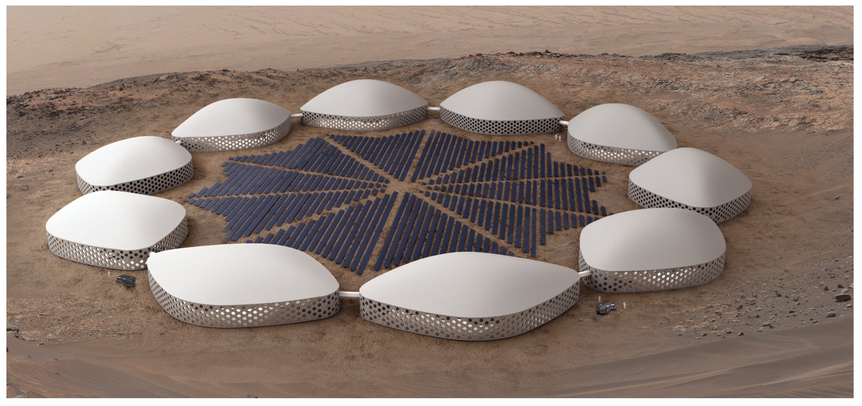
Figure 1. Martian Habitat Units (MHUs)—(Amini et al., 2022 [1]).
Aerospace 12 00761 g001
Figure 2. Martian Habitat Units (MHUs)—Plan I: ground floor level (bottom); Plan II: first floor level (top).
Aerospace 12 00761 g002
Figure 3. An exploded view diagram of a Martian Habitat Unit (MHU).
Aerospace 12 00761 g003
Figure 4. Positioning and orientation of the MHU in the computational domain.
Aerospace 12 00761 g004
Figure 5. Pressure distribution over the MHU: The highest pressure points represent the stagnation region of the bluff body.
Aerospace 12 00761 g005
Figure 6. Structure typology: Major hexagonal modules are used as the beams of the structure, leading to the primary input to the Karamba-3D simulations.
Aerospace 12 00761 g006
Figure 7. The vector representation of the direction forces on the MHU. The cyan-colored arrows represent forces containing only pressure and weight loads, while the yellow ones include wind loads as well.
Aerospace 12 00761 g007
Figure 12. Developing iteration stages in structural analysis for (1) linear structural components and (2) shell components. (a-1,a-2) Primary assessment: square cross-section columns. (b-1,b-2) Second stage modification: circular cross-section columns. (c-1,c-2) Addition of exterior walls. (d-1,d-2) Classification of the structural elements (see Figure 9)—extension of the design to address the interior/exterior pressure differences. (e-1,e-2) Final optimization.
Aerospace 12 00761 g012
Figure 13. (top) The schematic illustration of the compressive and tensile stress on beams and columns. (bottom) The schematic illustration of the compressive and tensile stress on the axial positions of the floors and walls. Red color is for the components under compressive stress, and blue is for the tensile stress.
Aerospace 12 00761 g013
Figure 14. Utilization rate for each stage during structural analysis, (a) linear components, (b) shell components (blue markers: tensile stress, red markers: compressive stress).
Aerospace 12 00761 g014
Figure 15. Utilization distribution for linear structural components of the MHUs across five progressive design stages. The left panels in each row (1) illustrate results for tension, while the right panels (2) show corresponding data for compression. Design stages: (a-1a-3) Initial configuration with rectangular column cross-sections. (b-1b-3) Columns replaced with circular cross-sections. (c-1c-3) Introduction of structurally active exterior shell walls. (d-1d-3) Grouping of structural components into three zones based on proximity to internal/external pressure boundaries, enabling differentiated cross-section sizing. (e-1e-3) Final stage using Karamba-3D’s cross-section optimization tool with predefined size ranges per group.
Aerospace 12 00761 g015
Figure 16. Utilization distribution for shell structural components of the MHUs across five progressive design stages. The left panels in each row (1) illustrate results for tension, while the right panels (2) show corresponding data for compression. Design stages: (a-1a-3) Initial configuration with rectangular column cross-sections. (b-1b-3) Columns replaced with circular cross-sections. (c-1c-3) Introduction of structurally active exterior shell walls. (d-1d-3) Grouping of structural components into three zones based on proximity to internal/external pressure boundaries, enabling differentiated cross-section sizing. (e-1e-3) Final stage using Karamba-3D’s cross-section optimization tool with predefined size ranges per group.
Aerospace 12 00761 g016
Figure 17. Optimization process and solutions during the primary set of analyses. (a) Pre-analyzed proposed structural components, exceeding the maximum utilization rate. (b) Addition of extra columns to the outer envelope to reduce the utilization rate, and (c) rectangular column utilization rate, exceeding 100%. (d) Cylindrical column utilization rate with better results compared to rectangular ones and subcritical behavior.
Aerospace 12 00761 g017
Figure 18. (a) Compressive and tensile stress rates on the horizontal structural members at three different levels of the structure, varying from −1.68 to +1.70 kN/cm2. Negative numbers (i.e., red colors) represent compression, and positive numbers and blue colors represent tension. (b) Utilization rate for the mentioned members varies from −94.3 to 98.7%. (c) Displacement rate on the horizontal structural members at three different levels of the structure, varying from 0.00 to 0.03 cm.
Aerospace 12 00761 g018
Figure 19. (a) Compressive and extensive tension rate on the columns from two different elevations, varying from −1.68 to +1.70 kN/cm2. Negative numbers (i.e., red colors) represent compression, and positive numbers and blue colors represent extension. (b) Utilization rate for the mentioned members varies from −94.3 to 98.7%. (c) Displacement rate on the columns from two different elevations, varying from 0.00 to 0.03 cm.
Aerospace 12 00761 g019
Figure 20. The displacement rate at three different levels of the structure varies from 0.00 to 0.03 cm.
Aerospace 12 00761 g020
Figure 21. Utilization rate on the slabs at three different levels of the structure, varying from −94.3 to 98.7%.
Aerospace 12 00761 g021
Figure 22. The illustration of the bearing surface of columns in a raft foundation and its divisions.
Aerospace 12 00761 g022
Figure 23. Final structural 3D model (in red) implemented on the MHU architectural 3D model in Rhinoceros 7. (Left) Structural columns, illustrated on the architectural plans to identify clashes. (Right) The collaborative structural and architectural 3D models presented at five different levels to identify beam and void clashes.
Aerospace 12 00761 g023
Table 1. Numerical grid characteristics.
ParameterSpecification
Surface layer thickness 0.25 m
Total number of cells3,083,925
Curvature normal angle18°
Min size3.08 × 10−3 m
Max size20 m
Boundary layer mesh5 leyers
Inflation growth rate2
Table 3. Categories of structural elements under different ranges of pressure.
Element TypeSub-CategoryCross-SecHeight
(cm)
Width
(cm)
columnexterior52.552.5
interior3030
beamexterior6060
interior3030
floorexterior 50-
interior 30-
wallexterior 40-
interior 27.5-
□: shape of the chosen cross-section for the structural elements.
Table 4. Finalized categories of structural elements.
Element TypeSub-CategoryCross-SecHeight
(cm)
Width
(cm)
Diameter
(cm)
Columnexterior--45–60
interior--20–40
Beamexterior40–8040–80-
interior20–4020–40-
Floorexterior 40–60--
interior 20–40--
Wallexterior 30–50--
interior 20–35--
○, □: shape of the chosen cross-section for the structural elements.
Disclaimer/Publisher’s Note: The statements, opinions and data contained in all publications are solely those of the individual author(s) and contributor(s) and not of MDPI and/or the editor(s). MDPI and/or the editor(s) disclaim responsibility for any injury to people or property resulting from any ideas, methods, instructions or products referred to in the content.