Abstract
In the electrification of low-altitude aircraft, aviation hybrid power systems have become one of the core research areas in this field due to their significant advantages of low emissions and long endurance. The energy management strategy is an important part of the design of aviation hybrid power systems and has a significant impact on the performance and safety.This paper first develops a 200 kW dual DC-bus series hybrid power system prototype for low-altitude aircraft and its Simulink simulation model; then, it proposes a rule-based energy management strategy that uses the smoothness of the state of charge (SOC) of energy storage batteries as a coordination criterion. The strategy is validated via ground tests, where the battery SOC remains above 30%, the system response time is within 5 s, and the DC-bus voltage fluctuation is within 1%. These results demonstrate the strategy’s feasibility, providing a reference for designing and implementing series hybrid power systems.
1. Introduction
Driven by sustained market expansion, the global fleet of operational aircraft is rapidly increasing, with associated fuel combustion releasing substantial carbon emissions—a concern highlighted in China’s 14th Five-Year Plan for Green Development in Civil Aviation (2022), which mandates urgent decarbonization. Statistics show that greenhouse gas emissions from the aviation industry account for approximately 2% of global emissions, significantly contributing to global warming [1]. The aviation industry has a significant impact on global warming. Without effective countermeasures, it is projected that by 2050, the aviation industry will cause a global temperature rise of 0.1 °C [2]. Therefore, reducing carbon emissions from the aviation industry and promoting the transformation of the aviation industry to green aviation is an urgent issue. Aviation hybrid power systems have become a promising research focus in the field of green aviation due to their lower carbon emissions, high fuel efficiency and less noise pollution [3]. Compared with battery-electric unmanned aerial vehicles (UAVs), fuel-powered UAVs have much higher fuel energy density than batteries, thus achieving a longer range [4]; while battery-electric UAVs are more advantageous in terms of environmental impact and system operational stability. Hybrid electric UAVs combine the advantages of both [5]. They not only reduce carbon emissions but also have a longer cruising range [6], thus becoming an important direction in UAV research. In hybrid UAVs, coordinating different power sources to optimize system performance and enhance safety constitutes a key task. Therefore, appropriate energy management strategies must be adopted to optimize the power allocation among power sources [7], making the operation of unmanned aerial vehicles more stable and efficient.
In terms of hybrid power systems, Wu Xiong et al. [8] analyzed the hybrid power systems of unmanned aerial vehicles based on their architectural forms, characteristics and current development status. They refined and analyzed four key technologies: overall design technology, high-efficiency and high-power-to-weight ratio motors, comprehensive energy management, and high-energy-density energy storage. They summarized the development trends of technical research and put forward targeted suggestions. Sun Xiaokang et al. [9] performed an overall design of the hybrid power system for a light general-aviation aircraft, established models of the turbine power generation system and the energy storage system, and subsequently conducted simulations of the series hybrid power system under two operating modes using these models. It was found that the designed hybrid power model reduced fuel consumption by 1.4% compared to the traditional propulsion system. Zhuang Weichao et al. [10] classified 14 possible hybrid power system configurations based on binary trees and discussed the future trends of hybrid power systems. Laurencas Raslavičius et al. [11] adopted the hybrid powertrain control algorithm in the design of hybrid electric vehicles, reducing fuel consumption and waste emissions.
In terms of the research on energy management strategies of hybrid power systems, scholars in China and abroad have conducted a large number of studies. The energy management strategies of hybrid power systems can be classified into three types: rule-based, optimization-based and intelligence-based. Rule-based energy management strategies are widely adopted due to their simplicity and ease of implementation. These strategies rely on predefined heuristic rules and fixed thresholds [12,13,14], which render them effective under known and steady-state conditions.Wang Zhe et al. [15] established component models of proton membrane fuel cells and batteries, as well as models of fuel cell/battery hybrid power systems. The energy management system was designed based on the idea of the finite state machine. Through simulation, it was verified that EMS can regulate the hybrid power system and rationally allocate the power of fuel cells and batteries to adapt to the changes in load power. Giampaolo Buticchi et al. [16] proposed a quadratic active bridge, which connected a hybrid storage system such as fuel cells, batteries and supercapacitors to the power distribution system of the aircraft, and proved through simulation that the proposed controller has good power control ability; Li Cheng et al. [17] designed an energy management strategy based on double-layer fuzzy control and optimized the control parameters using a genetic algorithm. Through experiments, it was verified that the double-layer fuzzy energy management strategy can improve the fuel economy and anti-interference ability of the system. In terms of optimization-based energy management strategies, Hu Chunming et al. [18] used the dynamic programming algorithm as the energy management strategy for oil–electric hybrid unmanned aerial vehicles. Through MATLAB simulation, they compared and analyzed the energy management strategies of the dynamic programming algorithm and those of fixed rules and fuzzy logic. The results show that the energy management strategy of the dynamic programming algorithm has smaller cumulative fuel consumption and average instantaneous fuel consumption, and also has better stability in the face of disturbances. Bongermino E et al. [19] proposed a dynamic programming algorithm for oil–electric hybrid unmanned aerial vehicles, built a Simulink simulation model composed of an internal combustion engine, a gearbox, an electric motor, an electric driver and lithium polymer, and verified that this control strategy has both optimal solution performance and a relatively fast solution speed. Learning-based energy management strategies, especially those adopting Deep Reinforcement Learning (DRL), represent the latest advances in the field of energy management [20,21,22]. Pedro Maroto Estrada et al. [23] developed a dual-deep Q-learning algorithm for energy management of the system, which reduces fuel consumption in the actual driving cycle. Yu Feifan et al. [24] proposed a strategy adopting a deep reinforcement learning method guided by prior knowledge. This approach integrates domain-specific knowledge into the deep deterministic policy gradient algorithm, aiming to improve learning efficiency and enhance fuel economy.
The paper is structured as follows: Section 2 elaborates the structure, main components, and subsystems of the 200 kW aeronautical hybrid power experimental platform constructed in this study. Section 3 then constructs a Simulink model of the experimental prototype and conducts simulation analysis on the platform, verifying its strong stability. Section 4 proposes a rule-based energy management strategy for the constructed prototype, using the smoothness of the battery state of charge (SOC) as a coordination criterion, and validates the strategy via ground tests on the prototype. Section 5 summarizes the entire work, while comparing deviations between the simulation model and the experimental prototype, and presents prospects for future research.
2. A 200 kW Aviation Hybrid Power System Test Platform
2.1. Test Platform Structure
The structural diagram of the 200 kW aviation hybrid power system test platform is shown in Figure 1.
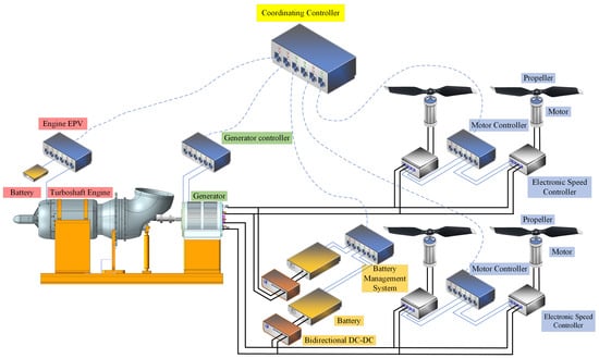
Figure 1.
Structural diagram of the test platform.
The 200 kW aviation hybrid power system test platform is primarily composed of four major components: the turboshaft-generator system (hereafter referred to as the turboshaft-electric (TSE) system), the power battery system, the electric propulsion system, and the control system.
2.2. System Operational Mode
The operational modes of the hybrid power system include the following four types:
(1) Hybrid mode: The TSE system and the battery system jointly supply power to the electric propulsion system.
(2) Charging mode: The TSE system powers the electric propulsion system while simultaneously charging the battery.
(3) Pure electric mode: The battery system supplies power to the electric propulsion system, with the TSE system inactive.
(4) Turboshaft-Electric mode: The TSE system powers the electric propulsion system, with the battery system inactive.
Based on different operational scenarios, the hybrid power system’s operational modes are determined, as shown in Table 1.

Table 1.
Operational modes of the hybrid power system under different scenarios.
2.3. Test Platform Component System
2.3.1. Turboshaft-Electric System
The TSE system consists of two main components: the turboshaft engine and the generator. As shown in Figure 2a, the turboshaft engine is positioned on the left side of the system, while the generator is located on the right.
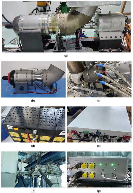
Figure 2.
Physical images of various components in the hybrid system. (a) TSE system. (b) Turboshaft engine. (c) High-speed generator. (d) Power battery pack. (e) Bidirectional DCDC converter. (f) Propeller. (g) Coordinating controller.
The engine section primarily consists of the turboshaft engine and the Engine Parameter Variable (EPV) system. The EPV system dynamically monitors and adjusts critical operating parameters of the turboshaft engine based on real-time operating conditions. When parameters approach the safety threshold, the EPV system initiates protective actions to maintain stable operation and prevent damage. This ensures the turboshaft engine operates efficiently across diverse scenarios while safeguarding its safety and service life. A physical diagram of the turboshaft engine is provided in Figure 2b.
The generator section mainly consists of a generator controller and a generator. Among them, the generator controller is responsible for connecting and coordinating the work between the controller and the generator, and controlling the start and stop of the generator according to the instructions issued by the coordinating controller. The physical diagram of the generator is shown in Figure 2c.
2.3.2. Power Battery System
The power battery system is mainly composed of batteries, a Battery Management System (BMS), bidirectional DC/DC converters, etc. Among them, individual batteries are first assembled into modules, with six modules serially connected to form the power battery pack. The pack exhibits the following specifications:
- Nominal energy: 8.3 kWh.
- Maximum charging power: 5 kW.
- Maximum output power: 20 kW.
The physical diagram of the power battery pack is shown in Figure 2d.
The BMS is the core control unit of the power battery system, responsible for managing the charging and discharging process of the battery and its health status [25]. Its main functions are:
(1) Battery status monitoring: Real-time monitoring of battery parameters such as voltage, current, and temperature to ensure that the battery operates within a safe working range.
(2) Manage the voltage of battery modules: Be responsible for balancing the voltage of battery modules operating in series to ensure that the status of each battery module is consistent and prevent overcharging or overdischarging of certain battery modules.
(3) Fault protection: Detect abnormal conditions such as overcharging, overdischarging, overheating or short circuit, and take timely measures, such as cutting off the circuit or alarming, to prevent battery damage or potential danger.
(4) Communication and control: The BMS exchanges information with the coordinating controller to ensure the collaborative operation of the entire system.
Bidirectional DC/DC converters are a key component for achieving energy conversion in the system. It can convert electrical energy between two different voltages and support the bidirectional flow of energy [26]. During charging, the bidirectional DC/DC adjusts the electrical energy generated by the TSE system to a voltage suitable for the battery for charging. During discharge, the energy stored in the battery is converted into the voltage required by the system through bidirectional DC/DC to power the propulsion system for use. The voltage range on the battery side of the bidirectional DC/DC is 200 to 850 V, and the maximum current on the battery side is 100 A. The maximum current on the DC bus side is also 100 A. The physical diagram of bidirectional DC/DC is shown in Figure 2e.
2.3.3. Electric Propulsion System
The electric propulsion system consists of a motor controller, a motor, an electronic speed controller (ESC), a propeller, etc.
The motor controller is the core control unit of the motor system, responsible for controlling the operation of the motor, including parameters such as speed and torque. It adjusts the working state of the motor according to the instructions from the coordinating controller or the flight control. The motor controller controls the output of the motor by adjusting the current and voltage to ensure that the system adjusts the rotational speed of the propeller according to different flight conditions. Meanwhile, the motor controller also monitors the working status of the motor to ensure its efficient and stable operation under different working conditions. The technical parameters of the motor controller adopted in this test are shown in Table 2.
Table 2.
Motor controller technical specifications.
The motor is the key component that drives the propeller. It receives control signals from the motor controller and the ESC, adjusts the rotational speed, and thereby controls the rotational speed of the propeller. The motor adopted in this test is the C235100 brushless motor. The specific parameters are shown in Table 3 as follows:
Table 3.
Brushless DC motor technical specifications.
The electric speed controller is an important component for controlling the rotational speed and power output of the motor. The communication interface of the ESC includes two CAN buses and one PWM signal. Among them, the main speed control is carried out through the PWM signal. One auxiliary CAN bus serves as a backup, while the other CAN bus is used for independent power status data interaction, uploading key data such as input voltage, output current, output speed, module temperature, chip temperature and motor temperature of the electronic controller in real time. The electronic speed controller adopts liquid cooling for heat dissipation. The maximum input voltage is DC850V, the maximum output current is AC500Arms, and the maximum output frequency is 1000 Hz. The main functions of the electronic speed controller are:
(1) Adjust the motor speed: The ESC adjusts the motor speed by controlling the frequency of the input voltage and current of the motor. It dynamically adjusts the running speed of the motor according to the instructions issued by the motor controller to ensure that the propeller generates an appropriate thrust.
(2) Brushless motor drive: For the brushless motor used in this test, the ESC is responsible for converting direct current into three-phase alternating current to drive the motor, and at the same time adjusting the frequency of the current to control the rotation direction and speed of the motor.
(3) Precise power control: The ESC can precisely control the power output of the motor, thereby optimizing energy consumption. Due to the different thrust requirements during different flight phases such as takeoff, hovering and cruising, adjusting the power output of the motor is crucial for the aircraft.
(4) High-voltage discharge function: When the main power supply is disconnected, it can actively release the high-voltage electricity stored in the capacitive devices on the circuit.
(5) Comprehensive protection mechanisms: including overvoltage protection, undervoltage protection, throttle loss protection, over-temperature protection, overcurrent protection, etc. Different protection mechanisms use distinct handling strategies, which can be combined with flight control for further fault diagnosis and handling.
The physical diagram of the propeller is shown in Figure 2f.
The propeller plays a crucial role in an aircraft. Its main function is to generate thrust through rotation, propelling the aircraft to fly forward or take off and land vertically. The propeller is connected to the motor. When the motor rotates, it drives the propeller to rotate. The propeller accelerates the surrounding air through rotation, generating thrust and propelling the unmanned aerial vehicle forward. By adjusting the rotational speed and angle, the propeller can control the magnitude of the propulsion force of the aircraft. The flight control system ensures that the aircraft can accelerate, decelerate and change direction smoothly by adjusting the power of the propellers. Meanwhile, the rotational speed difference between the left and right propellers can also be used for heading control.
The weight of a single propeller used in this test was (2000 ± 100) g, and the material used was a composite of carbon fiber and epoxy resin. This composite material makes the propeller both lightweight and highly strong, capable of withstanding the tremendous pressure and stress during high-speed rotation. The diameter of the propeller is 78 inches, and the geometric pitch is 20 inches.
2.3.4. Control System
The control system consists of a flight controller and a coordination controller. Flight control is mainly responsible for controlling the attitude, position and flight status of the aircraft. It acquires the real-time status of the aircraft through sensors, controls the propellers, motors and other actuating mechanisms, thereby stabilizing and adjusting the flight attitude of the aircraft.
The coordinating controller connects the engine system, generator system, battery system and motor system, and is responsible for coordinating the operation of each subsystem. It optimizes operational efficiency by managing inter-module data communication and ensuring coordinated subsystem operation. The physical diagram of the coordinating controller is shown in Figure 2g.
The coordinating controller used in this test is the NI Compact RIO-9033. Its network port supports communication rates of 10 Mbit · s−1 and 100 Mbit · s−1, with a maximum communication distance of 100 m. The RS-232, RS-485, and RS-422 serial ports all have a maximum baud rate of 115,200 bit · s−1 and a 30 m maximum communication distance. The controller measures 219.5 mm × 88.1 mm × 109.2 mm and weighs 1.8 kg.
3. System Modeling and Simulation Analysis
Dynamic simulation plays an irreplaceable and crucial role in the development process of aviation hybrid electric propulsion systems. Compared with the more mature static or quasi-static models at the present stage, dynamic simulation can more accurately depict the complex response characteristics of the system when dealing with actual working conditions such as environmental changes and sudden disturbances. This is critical for designing efficient, safe and stable aviation hybrid electric propulsion systems. The following text will conduct modeling and simulation analysis on the 200 kW hybrid power system established in Section 2.
3.1. System Modeling
The methods for establishing the mathematical model of turboshaft engines mainly include analytical methods and experimental methods [27]. The analytical method, also known as the component-level modeling method, is based on the theory of aerothermodynamics and uses mathematical formulas to analyze the working characteristics of each sub-component of the turboshaft engine, respectively. The test method, also known as the system identification method, mainly processes the real test data of the turboshaft engine and uses the mathematical expressions obtained by the identification method to describe the engine characteristics, thereby obtaining the whole-machine model [28].
At present, in China and abroad, the analytical method is mostly adopted to establish the component-level mathematical model of the turboshaft engine. The established model has relatively high accuracy and can simulate the dynamic and steady-state characteristics of the engine within the full envelope range. However, the difficulty of refined modeling is relatively high. Researchers [29,30,31] have partially linearized the modeling process to reduce the dimension of the nonlinear equation system. Although the model accuracy has been reduced to a certain extent, the computational efficiency has been significantly improved, and the accuracy is still considerable.
This study also adopts the analytical method for modeling and refers to the experience of predecessors. On the basis of not significantly affecting the performance accuracy of the engine, the following assumptions are specially made to simplify the modeling process:
(1) The dynamic process of the engine mainly considers the influence of rotor inertia;
(2) Thermal inertia, heat storage, volumetric effect, etc., are not taken into account, and the changes in component efficiency and total pressure loss coefficient during the dynamic processes are ignored.
When modeling, first, based on the real structure of the turboshaft engine in the test system, the model is divided into sub-components such as the intake port, compressor, combustion chamber, gas turbine, power turbine and exhaust pipe, as shown in Figure 3, and the cross-sectional positions of different components are divided. Secondly, each relatively independent component is described, respectively, with the corresponding aerothermodynamic equations. Among them, the compressor, gas turbine and power turbine play a key role in the overall performance of the turboshaft engine, especially involving complex aerothermodynamic processes, and it is particularly necessary to introduce additional characteristic diagrams for description [32]. However, precise component-level characteristic data is difficult to obtain and is replaced by general characteristic maps during the modeling process. Among them, Section 0: Airflow far in front of the engine; Section 1: Inlet of the air inlet; Section 2: Compressor inlet; Section 3: Compressor outlet/combustion chamber inlet; Section 4: Outlet of the combustion chamber; Section 41: Inlet of gas turbine; Section 42: Gas turbine outlet; Section 45: Power turbine outlet; Section 9: Tail nozzle outlet.
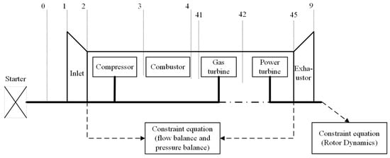
Figure 3.
Schematic diagram of turboshaft engine components.
Then, the steady-state co-working equations of each sub-component are established based on the balance of flow rate, pressure and power. Based on the flow rate and pressure balance, and combined with rotor dynamics, a dynamic co-working equation is established. Finally, by using the Newton–Raphson algorithm [33] to iteratively solve the common working equations, the steady-state model and dynamic model of the turboshaft engine were established, respectively. Among them, the common working conditions that the engine needs to meet to maintain stable operation mainly include:
(1) Gas turbine inlet flow balance;
(2) Inlet flow balance of the power turbine;
(3) Gas pressure balance at the exhaust pipe outlet;
(4) Power balance between the gas turbine and the compressor;
(5) Power balance between the power turbine and the load;
The turboshaft engine under steady state needs to simultaneously meet all the conditions (1) to (5) above. When the turboshaft engine is in a dynamic process, only (1) to (3) needs to be satisfied, but the power balance condition is not met. The power difference among them changes the rotational speed of the rotating components through rotor dynamics.
Based on the real test data of the turboshaft engine in the early stage, comparisons between simulated and experimental data show that the maximum deviation between the two does not exceed 7%, indicating that the simulation model has relatively high accuracy. Data deviations may stem from certain discrepancies between the working characteristics of the components of the real engine and the general characteristic diagrams used in the modeling process, as well as some condition assumptions made during the modeling process. In the future, the model can be iteratively corrected based on the test data to improve its accuracy.
The generator, motor and battery models in the simulation were developed based on the Simscape Electrical Specialized Power Systems (SPSs) components built into the Simulink simulation platform. The generator and motor adopt the Permanent Magnet Synchronous Machine (PMSM) in the SPS library, and the lithium-ion battery is selected for the power battery. The specific parameters of the generator model, the motor model and the power battery model are, respectively, shown in Table 4, Table 5 and Table 6.
Table 4.
Generator model parameters.
Table 5.
Motor model parameters.
Table 6.
Power battery model parameters.
The motor and power battery models should also, respectively, include the corresponding AC/DC rectifiers, DC/DC choppers, DC/AC inverters and their control strategies. Among them, insulated gate bipolar transistors (IGBTs) are uniformly selected as switching devices, and the control strategy will be further analyzed in the following text.
3.2. Simulation Analysis
Bus voltage stability is the foundation for the stable operation of DC microgrid systems. This requires that in TSE systems and power battery systems, there must be exactly one energy system responsible for maintaining a constant DC bus voltage. Therefore, the control strategy of the integrated system should include two main forms: “ turboshaft-electric system voltage stabilization” or “power battery voltage stabilization”. Owing to the order-of-magnitude difference in time scales between the turboshaft engine’s thermodynamic system and power-electronic devices, adopting the “turboshaft-electric system voltage stabilization” strategy may prolong transition times during dynamic processes. “Power battery voltage stabilization”, on the other hand, has a faster response speed and is relatively more conducive to enhancing the dynamic stability of the system.
Based on this, the power battery and its DC/DC chopper adopt a double closed-loop Proportional–Integral (PI) control with an outer voltage loop and an inner current loop to maintain a constant bus voltage and have the ability of bidirectional power flow, that is, the ability to switch between charging and discharging states. The TSE system regulates according to the power command. On the one hand, the engine regulates the fuel flow through an open loop. On the other hand, the high-speed generator takes the torque and rotational speed of the engine output shaft as the model input and adopts the control strategy of the outer loop of rotational speed PI and the inner loop of current Finite Control Set Model Predictive Control (FCS-MPC) to efficiently convert mechanical power into electrical power and inject it into the DC microgrid. The control strategy of the integrated system is shown in Figure 4, and control parameters are shown in Table 7.
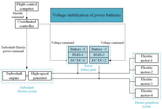
Figure 4.
A schematic diagram of integrated system control strategy.
Table 7.
Control parameters for the integrated system.
Based on the modeling and design of each main component and its controller, the system adopts the “reverse simulation method”, that is, starting from the required power of the load motor under different working conditions, the working state of the energy system is adjusted in reverse. To sum up, the integrated dynamic simulation model of the 200 kW-class series-connected aviation hybrid electric propulsion system is shown in Figure 5.
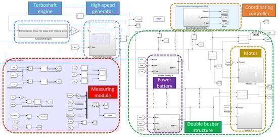
Figure 5.
Dynamic simulation model of a 200 kW class series hybrid electric propulsion system for aviation.
When the motor operates stably with a power output of 105 kW under the predetermined cruising condition, the working status of all components of the system is normal. Suppose the power demand of the load fluctuates by approximately “+10 kW to 0 to −10 kW∼0” to simulate the state changes of the system under sudden disturbances. As shown in Figure 6a, the power battery pack can quickly track load changes with a near-instantaneous response, while the TSE system is allowed to achieve state regulation for a longer time. Among them, when = 6 s, the load demand decreases and the generation power is greater than the load power. At this time, the power battery pack absorbs the redundant electrical energy on the DC bus to charge itself, and the power performance is negative, which is in line with the expected design requirements. As shown in Figure 6b, the hybrid propulsion system switches from the cruise condition to the takeoff condition at , with the electric motor gradually ramping up to full-power output. At , it reaches the takeoff condition, i.e., the maximum-power (200 kW) output point. At , the system transitions to the climb condition, and the power decreases gradually. At , it arrives at the climb-condition power point (170 kW). At , the system switches to the idle condition and reaches the idle condition at .
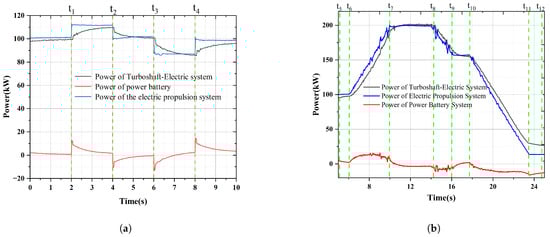
Figure 6.
Simulated power curve. (a) Subsystem power under 10 kW disturbance. (b) Subsystem power under switching between different operating conditions.
From the perspective of the rotational speed of the TSE system, the rotational speed variation in the system under disturbed conditions mainly stems from the “active” regulation of the fuel flow by the turboshaft engine. For instance, at = 2 s and = 4 s, in response to the load change, the turboshaft engine increases or decreases the throttle ratio accordingly, and the unit speed increases or decreases first. Subsequently, constant speed control is carried out by the generator and its AC/DC rectifier. Due to the high control frequency of the generator system, rotational speed variation remained within 0.2%, and the regulation time was less than 1 s, with no obvious fluctuations occurring. The simulation rotational speed curve is shown in Figure 7a,b.
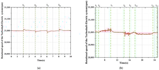
Figure 7.
Simulated rotational speed curve. (a) Rotational speed of the turboshaft-electric system under 10 kW disturbance. (b) Rotational speed of the turboshaft-electric system under switching between different operating conditions.
Overall, based on the control strategy centered on “power battery voltage stabilization” in this chapter, a dynamic simulation model of the 200 kW-class series-connected aviation hybrid electric propulsion system has been established. This model covers multiple subsystems and their control strategies. The simulation results show that this model has a high degree of credibility. The adopted control strategy exhibits robust performance under perturbations, meets the established design requirements, and can be iteratively designed and optimized with the test system.
4. Energy Management Architecture and Experimental Verification
4.1. Energy Management Architecture
The energy management architecture of this system is shown in Figure 8:
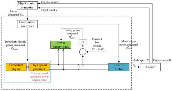
Figure 8.
Energy management architecture.
The energy management strategy is shown in Figure 9. When the flight control computer issues instructions, the Central Control Unit (CCU) provides thrust by adjusting the rotational speed of the motor/propeller and simultaneously consumes the busbar power. Upon bus voltage drop, the power battery automatically discharges to supplement bus power. The coordinating controller changes the output power of the power battery by regulating the TSE power. Conversely, when the aircraft issues the load reduction command, the bus power increases, and the excess electrical energy will be replenished to the power battery pack in the form of charging, thereby achieving the bidirectional power flow.
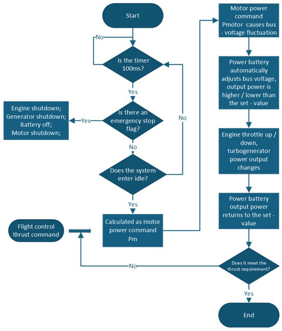
Figure 9.
Energy management strategy.
Based on this strategy, the derivation steps of the power flow are presented in the following. This paper simplifies the flight control computer’s control objectives to aircraft flight altitude H and speed V, deriving the system’s power demand. Upon receiving flight control power demand , CCU controls the electric propulsion system to generate thrust, resulting in:
where is the updated power command for the electric propulsion system.
In practice, the propulsion system’s power loading/unloading follows a ramp profile with slope k:
- If > , k > 0 (increasing power).
- If < , k < 0 (decreasing power).
represents the electric propulsion power in the next control cycle. Without considering the losses, the system power is in an unbalanced state at this moment.
The power battery adopts voltage-stabilizing control. When the bus power is unbalanced, the power battery will automatically adjust the output current to stabilize the bus voltage, so that the bus power returns to balance again. The following formula can be obtained:
The CCU sets the discharge power threshold and the charging power threshold of the power battery, denoted as and , respectively, and controls the output power of the power battery in each control cycle.
Take the positive discharge process of the power battery as an example: If , increase the power of the turbocharger to reduce the output power of the power battery. The adjustment amplitude of the TSE power in each control cycle is set to 1 kW, which can be described as:
where represents the TSE power of the previous control cycle.
Through the voltage-stabilizing control of the power battery and the battery power limitation of the CCU, the bus power balance is ultimately achieved.
Since the power battery serves as the voltage-stabilizing source of the system, battery health management directly affects the stable operation of the entire system. The battery SOC health management strategy is proposed, as shown in Figure 10.
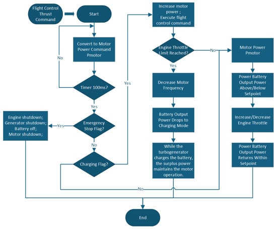
Figure 10.
Battery SOC health management strategy.
If the SOC of the battery is lower than the threshold, it will enter the charging mode. At this time, the CCU preferentially executes the charging logic of the power battery. Let
where is the charging power of the power battery, which is a negative value. At this time, the motor power is adjusted as follows:
where is the maximum power of the TSE system.
4.2. Experimental Verification
The energy management strategy was verified through a 200 kW hybrid ground test platform. This test platform adopts a dual-bus DC 540 V architecture, with a set of power battery packs and an electric propulsion system connected in parallel on each busbar. The test parameters for verifying the energy management strategy are shown in Table 8 as follows.
Table 8.
Experimental parameters of the energy management strategy validation.
Figure 11 shows the bus voltage stabilizes around 540 V (rated). During the test process, as the coupling operation of multiple components accompanied the increase in the output power of the electric propulsion system, the voltage fluctuation state was amplified. The maximum fluctuation amplitude does not exceed 2 V, which is much less than 1% of the rated voltage, indicating that the system is in good operating condition.
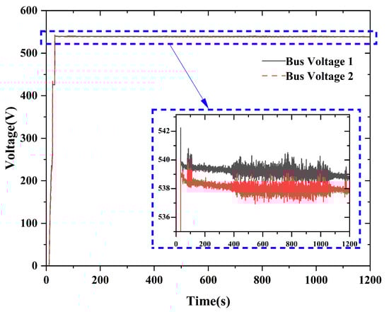
Figure 11.
Experimental results of busbar voltage.
The system output power is shown in Figure 12, and the motor loading slope and the TSE loading slope are shown in Figure 13. The electric propulsion system starts loading approximately at 385 s and ends loading at 430 s. The entire process lasts for about 45 s. The TSE system begins to load approximately at 393 s and ends loading at 428 s, lasting for about 35 s. Loading duration differences arise because the power battery stabilizes voltage. The coordinating controller allows the system’s operating power to fluctuate within a range of 4 kW. Only when the power fluctuation exceeds 4 kW will the TSE power be adjusted.
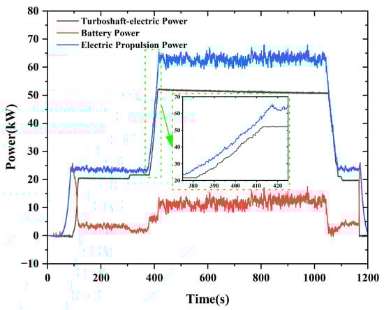
Figure 12.
The experimental results of the system output power.
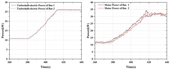
Figure 13.
Motor loading slope and turboshaft-electric loading slope.
The comparison between turboshaft-electric power and the rotational speed of the gas turbine is shown in Figure 14. The gas turbine rotational speed maintains a stable plateau during the power output phase, which is critical for the hybrid power system’s operation. Such stable speed ensures continuous mechanical energy supply, enabling the power turbine, battery, and electric propulsion system to work in coordination. It also avoids efficiency losses or component wear from abrupt speed fluctuations, laying a foundation for reliable energy management and system performance.
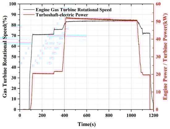
Figure 14.
Comparison of turboshaft-electric power and gas turbine speed.
In the TSE system, the engine is in the Np control mode. As the power demand of the generator changes, the engine will automatically adjust the throttle to meet the power demand. As shown in Figure 15, the SOC of the battery pack 1 and the battery pack 2 changed during the test process.
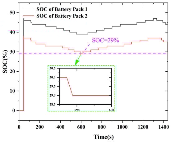
Figure 15.
SOC variation curves of the battery pack 1 and the battery pack 2.
Figure 16 shows the variation curves of the corresponding turboshaft-electric power, battery power and electric propulsion power during the test process.
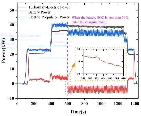
Figure 16.
Variation curves of turboshaft-electric power, battery power, and electric propulsion power.
(1) As shown in Figure 15 and Figure 16, the system enters the charging protection state during operation. The SOC of the power batteries at startup is 34% and 44%, respectively. After entering the energy management operation for about 3 min, the battery power drops to 29%, and it enters the charging stage.
(2) The output limit of the engine is 45 kW shaft power, but the actual output power is approximately 40 kW, which cannot meet the dual demands of battery charging and motor operation. Therefore, the motor operates at reduced power.
(3) As the battery SOC increased from 29% to 36%, the engine’s output power was further constrained to 40 kW, causing the motor power to decrease continuously.
(4) After running at reduced power, the system needs to stabilize and then a shutdown command can be issued.
(5) During the process from shutdown to slow operation, the engine throttle limit is set at 24 kW of shaft power, and the electric motor power limit is also 24 kW. At this time, the battery no longer charges but switches to a discharging state.
(6) After the slow vehicle process is completed, the system stops normally.
As can be seen from the figure, during the process of the system’s operating state changing, all components can successfully re-enter the steady state and operate stably according to the set program. This process fully verified the effectiveness of the energy management strategy.
5. Conclusions
This paper first establishes a 200 kW dual DC bus series hybrid power system, including the TSE system, power battery system, electric propulsion system and coordinated control system, conducts a simulation analysis on this aviation hybrid power system, and draws the following conclusions:
(1) Under steady cruising conditions with a 105 kW motor output, the system maintains stable operation with minimal parameter deviations.
(2) When the load power fluctuates, the power battery can quickly track the corresponding load changes.
(3) During load variations, the TSE system’s rotational speed exhibits minimal fluctuations, with simulation curves showing stable behavior.
(4) This system has good stability and performs well and in a controlled manner under disturbed conditions.
In this study, both simulation and physical experiments were conducted on the 200 kW hybrid system under load conditions of 35 kW, 55 kW, and 80 kW, respectively. The experimental results are illustrated in Figure 17. Specifically:
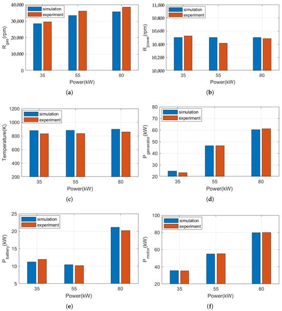
Figure 17.
Simulation vs experimental test comparisons. (a) Gas turbine rotational speed system. (b) Power turbine rotational speed. (c) Power turbine exit temperature. (d) High-speed generator output power. (e) Battery power. (f) Electric motor output power.
- Figure 17a shows the comparison between simulation and physical test results of the engine’s gas turbine rotational speed;
- Figure 17b presents the comparison of the engine’s power turbine rotational speed between simulation and physical test;
- Figure 17c displays the comparison of the high-speed generator output power between simulation and physical test;
- Figure 17d illustrates the comparison of the engine’s gas turbine rotational speed between simulation and physical test;
- Figure 17e shows the comparison of the power battery output power between simulation and physical test;
- Figure 17f presents the comparison of the electric motor output power between simulation and physical test.
With the physical test results as the reference, the errors between simulation and physical experiments were calculated. The specific error values are detailed in Table 9. As shown in the table, for the 200 kW hybrid power system developed in this study, the maximum error of all key parameters between the simulation and physical tests does not exceed 8%. The results indicate that the constructed simulation model demonstrates high fidelity with the physical tests, and all deviations fall well within the acceptable engineering thresholds, thereby validating the high-precision performance of the model in system analysis.
Table 9.
Error table for simulation vs physical test comparisons.
Finally, in this paper, through the established 200 kW hybrid ground test platform, the energy management strategy with the smoothness of the SOC of the energy storage battery as the coordination index was experimentally verified. The experimental results show that when the battery SOC drops below 30%, the system can rapidly adjust the output power of the TSE system and the battery system autonomously, restoring the battery SOC to above 30%. During this process, all components can quickly re-enter the steady state, with the system response time not exceeding 5 s and the voltage ripple within 2 V, thus proving the effectiveness of this energy management strategy.
Future work aims to successfully apply this hybrid power system to actual low-altitude aircraft to provide power for them. In addition, advances in processor computing power, coupled with the integration of intelligent algorithms, will progressively enhance the system’s stability and robustness in aviation applications.
Author Contributions
Conceptualization: Y.S. and K.F.; methodology: Y.S.; software: Y.S.; validation: Y.S., K.F., M.S. and B.D.; formal analysis: Y.S.; investigation: Y.S.; resources: Y.S.; data curation: Y.S.; writing—original draft preparation: Y.S.; writing—review and editing: Y.S.; visualization: Y.S.; supervision: Y.S.; project administration: Y.S.; funding acquisition: K.F. All authors have read and agreed to the published version of the manuscript.
Funding
This work was supported by the Aeronautical Science Foundation of China under Grant 2024L039068001.
Data Availability Statement
The original contributions presented in the study are included in the article, further inquiries can be directed to the corresponding author.
Acknowledgments
The authors would like to express their sincere thanks to the Aeronautical Science Foundation of China for providing the budget for this project.
Conflicts of Interest
The Author Yunfeng She was employed by the company AECC Commercial Aircraft Engine Co., Ltd. The remaining authors declare that the research was conducted in the absence of any commercial or financial relationships that could be construed as a potential conflict of interest.
Abbreviations
The following abbreviations are used in this manuscript:
| SOC | state of charge |
| UAVs) | unmanned aerial vehicles |
| TSE | turboshaft-electric |
| EPV | Engine Parameter Variable |
| BMS | Battery Management System |
| SVPWM | Space Vector Pulse Width Modulation |
| FOC | Field-Oriented Control |
| SPS | Simscape Electrical Specialized Power Systems |
| PMSM | Permanent Magnet Synchronous Machine |
| IGBTs | insulated gate bipolar transistors |
| PI | Proportional-Integral |
| FCS-MPC | Finite Control Set Model Predictive Control |
| CCU | Central Control Unit |
References
- Abrantes, I.; Ferreira, A.F.; Silva, A.; Costa, M. Sustainable Aviation Fuels and Imminent Technologies—CO2 Emissions Evolution Towards 2050. J. Clean. Prod. 2021, 313, 127937. [Google Scholar] [CrossRef]
- Klöwer, M.; Allen, M.R.; Lee, D.S.; Proud, S.R.; Gallagher, L.; Skowron, A. Quantifying Aviation’s Contribution to Global Warming. Environ. Res. Lett. 2021, 16, 104027. [Google Scholar] [CrossRef]
- Xue, D.; Chen, X.M.; Yu, S. Sustainable aviation for a greener future. Commun. Earth Environ. 2025, 6, 233. [Google Scholar] [CrossRef]
- Bdour, J.; Sababha, B.H. A Hybrid Thrusting System for Increasing the Endurance Time of Multirotor Unmanned Aerial Vehicles. Int. J. Adv. Robot. Syst. 2023, 20, 1–13. [Google Scholar] [CrossRef]
- Friedrich, C.; Robertson, P.A. Hybrid-electric propulsion for automotive and aviation applications. CEAS Aeronaut. J. 2015, 6, 279–290. [Google Scholar] [CrossRef]
- Fornaro, E.; Cardone, M.; Dannier, A. A Comparative Assessment of Hybrid Parallel, Series, and Full-Electric Propulsion Systems for Aircraft Application. IEEE Access 2022, 10, 28808–28820. [Google Scholar] [CrossRef]
- Cho, K.; Kim, W. Real-Time Predictive Energy Management Strategy for Fuel Cell-Powered Unmanned Aerial Vehicles Based on the Control-Oriented Battery Model. IEEE Control Syst. Lett. 2023, 7, 943–948. [Google Scholar] [CrossRef]
- Wu, X.; Shen, X.; Song, H.Q. Comprehensive Analysis of Hybrid Power Systems for UAVs. J. Propuls. Technol. 2022, 43, 6–18. [Google Scholar] [CrossRef]
- Sun, X.K. Modeling and Control Research of Series Hybrid Power System Based on Turboshaft Engine. Master’s Thesis, Nanjing University of Aeronautics and Astronautics, Nanjing, China, 2022. [Google Scholar]
- Zhuang, W.; Li, S.; Zhang, X.; Kum, D.; Song, Z.; Yin, G.; Ju, F. A survey of powertrain configuration studies on hybrid electric vehicles. Appl. Energy 2020, 262, 114553. [Google Scholar] [CrossRef]
- Raslavicius, L.; Kersys, A.; Makaras, R. Management of hybrid powertrain dynamics and energy consumption for 2WD, 4WD, and HMMWV vehicles. Renew. Sustain. Energy Rev. 2017, 68, 380–396. [Google Scholar] [CrossRef]
- Yuan, H.-B.; Zou, W.-J.; Jung, S.; Kim, Y.-B. A Real-Time Rule-Based Energy Management Strategy With Multi-Objective Optimization for a Fuel Cell Hybrid Electric Vehicle. IEEE Access 2022, 10, 102618–102628. [Google Scholar] [CrossRef]
- Ji, S.; An, Z.; Yang, G.; Jia, H.; Qi, B. Research on voltage stability improvement and energy management strategies for the collaborative power supply system of proton exchange membrane fuel cells and Li–S battery. Ionics 2024, 30, 5361–5377. [Google Scholar] [CrossRef]
- Abdelhedi, F.; Jarraya, I.; Bawayan, H.; Abdelkeder, M.; Rizoug, N.; Koubaa, A. Optimizing Electric Vehicles efficiency with hybrid energy storage: Comparative analysis of rule-based and neural network power management systems. Energy 2024, 313, 133979. [Google Scholar] [CrossRef]
- Wang, Z.; Guo, Y.Q. Hybrid Power System Modeling and Application of Energy Management Strategy. Aeroengine 2019, 45, 7–11. [Google Scholar] [CrossRef]
- Buticchi, G.; Costa, L.; Barater, D.; Liserre, M.; Amarillo, E. A Quadruple Active Bridge Converter for the Storage Integration on the More Electric Aircraft. IEEE Trans. Power Electron. 2018, 33, 8174–8186. [Google Scholar] [CrossRef]
- Li, C. Research on Dual Fuzzy Energy Management Strategy for UAV Extended-Range Hybrid Electric Propulsion System. Master’s Thesis, Tianjin University, Tianjin, China, 2021. [Google Scholar]
- Hu, C.M.; Yan, D.Y.; Liu, N.; Song, X.J. Comparative Simulation Study of Energy Management Strategies for Oil-Electric Hybrid UAVs. Intern. Combust. Engine Eng. 2022, 43, 74–83. [Google Scholar] [CrossRef]
- Bongermino, E.; Tomaselli, M.; Monopoli, V.; Rizzello, G.; Cupertino, F.; Naso, D. Hybrid Aeronautical Propulsion: Control and Energy Management. In Proceedings of the Control Conference Africa (CCA), Johannesburg, South Africa, 7–8 December 2017; pp. 169–174. [Google Scholar]
- Jouda, B.; Al-Mahasneh, A.J.; Abu Mallouh, M. Deep stochastic reinforcement learning-based energy management strategy for fuel cell hybrid electric vehicles. Energy Convers. Manag 2024, 301, 117973. [Google Scholar] [CrossRef]
- Huang, Y.; Kang, Z.; Mao, X.; Hu, H.; Tan, J.; Xuan, D. Deep reinforcement learning based energymanagement strategy considering running costs and energy source aging for fuel cell hybrid electric vehicle. Energy 2023, 283, 129177. [Google Scholar] [CrossRef]
- Zhou, Y.; Huang, Y.; Mao, X.; Kang, Z.; Huang, X.; Xuan, D. Research on energy management strategy of fuel cell hybrid power via an improved TD3 deep reinforcement learning. Energy 2024, 295, 130564. [Google Scholar] [CrossRef]
- Estrada, P.; de Lima, D.; Bauer, P.; Mammetti, M.; Bruno, J. Deep learning in the development of energy management strategies of hybrid electric vehicles: A hybrid modeling approach. Appl. Energy 2023, 329, 120231. [Google Scholar] [CrossRef]
- Yu, F.; Tang, W.; Chen, J.; Wang, J.; Sun, X.; Chen, X. Deep Reinforcement Learning Based Energy Management Strategy for Vertical Take-Off and Landing Aircraft with Turbo-Electric Hybrid Propulsion System. Aerospace 2025, 12, 355. [Google Scholar] [CrossRef]
- Kurkin, A.; Chivenkov, A.; Aleshin, D.; Trofimov, I.; Shalukho, A.; Vilkov, D. Battery Management System for Electric Vehicles: Comprehensive Review of Circuitry Configuration and Algorithms. World Electr. Veh. J. 2025, 16, 451. [Google Scholar] [CrossRef]
- Lai, C.-M.; Cheng, Y.-H.; Hsieh, M.-H.; Lin, Y.-C. Development of a Bidirectional DC/DC Converter with Dual-Battery Energy Storage for Hybrid Electric Vehicle System. IEEE Trans. Veh. Technol. 2018, 67, 1036–1052. [Google Scholar] [CrossRef]
- Liang, N.N. Research on Modeling and Control Laws of Aero-Turboshaft Engines. Master’s Thesis, Nanjing University of Aeronautics and Astronautics, Nanjing, China, 2011. [Google Scholar]
- Lian, X.C.; Wu, H. Principles of Aero Engines; Northwestern Polytechnical University Press: Xi’an, China, 2005. [Google Scholar]
- Duyar, A.; Gu, Z.; Litt, J. A simplified dynamic model of the T700 turboshaft engine. J. Am. Helicopter Soc. 1995, 40, 62–70. [Google Scholar] [CrossRef]
- Liu, J.; Yu, J.; Xie, Z. Applying UML to Gas Turbine Engine Simulation. In Proceedings of the Technology of Object-Oriented Languages and Systems (TOOLS 31), Nanjing, China, 22–25 September 1999; p. 458. [Google Scholar]
- Gaudet, S.R. Development of a Dynamic Modeling and Control System Design Methodology for Gas Turbines. Ph.D. Thesis, Carleton University, Ottawa, ON, Canada, 2007. [Google Scholar]
- Kong, C.; Ki, J.; Kang, M. A New Scaling Method for Component Maps of Gas Turbine Using System Identification. J. Eng. Gas Turbines Power 2003, 125, 979–985. [Google Scholar] [CrossRef]
- Plencner, R.M. Plotting Component Maps in the Navy/NASA Engine Program (NNEP)—A Method and Its Usage; NASA Technical Memorandum 101433; Lewis Research Center: Cleveland, OH, USA, 1989. [Google Scholar]
Disclaimer/Publisher’s Note: The statements, opinions and data contained in all publications are solely those of the individual author(s) and contributor(s) and not of MDPI and/or the editor(s). MDPI and/or the editor(s) disclaim responsibility for any injury to people or property resulting from any ideas, methods, instructions or products referred to in the content. |
© 2025 by the authors. Licensee MDPI, Basel, Switzerland. This article is an open access article distributed under the terms and conditions of the Creative Commons Attribution (CC BY) license (https://creativecommons.org/licenses/by/4.0/).