1. Introduction
Vehicular communication is crucial for the future of intelligent transportation systems (ITS) and smart cities, playing a key role in enhancing road safety, traffic management, and driving efficiency [
1,
2]. This communication network helps prevent accidents through collision warnings, optimizes traffic flow by coordinating vehicle speeds, and reduces congestion by providing real-time traffic updates [
1,
2]. However, maintaining high-data-rate communications in harsh environments like highways and in remote or disaster-stricken areas constitutes a challenging task [
1,
2]. In this regard, unmanned aerial vehicle (UAV)-assisted vehicular communications are pivotal in advancing the efficiency and reach of vehicular networks, particularly in these environments where traditional ground-based base stations (BSs) fall short [
3,
4]. Unlike fixed ground BSs, UAVs can be dynamically deployed and repositioned to ensure optimal coverage and connectivity, making them more cost-effective and adaptable to changing network demands. Their ability to maintain line-of-sight (LoS) connections at varying altitudes enables millimeter-wave (mmWave)-based communications, essential for high-bandwidth applications such as autonomous driving and real-time data transmission [
5,
6]. Moreover, the use of directional mmWave communication can enhance the security of systems against jammers and eavesdroppers. UAVs also offer rapid deployment and scalability, making them ideal for temporary communication needs during large events or emergencies [
7].
Selecting the optimal UAV from those currently covering a vehicle presents a significant challenge in UAV-assisted vehicular communications utilizing the mmWave band. The criteria for selecting the optimal UAV are to maximize the vehicle’s achievable data rate and ensure a long coverage period to prevent frequent handovers, which are limited by the UAVs’ remaining battery capacities. Moreover, the vehicle should autonomously select the most suitable UAV from its available options to minimize control overhead, particularly in environments with a limited number of deployed BSs. However, the vehicle lacks prior knowledge of essential UAV parameters, such as their flying speeds, altitudes, and precise positions. This information is critical for accurately predicting individual UAVs’ coverage durations and for forming the transmit (Tx) and receive (Rx) mmWave beams necessary for assessing achievable data rates, thereby facilitating the selection of the optimal UAV.
In this paper, to estimate the flying altitudes, speeds, and positions of the UAVs, we utilized out-of-band Delay-Doppler (DD) channel state information (CSI) with orthogonal time-frequency space (OTFS) modulation [
8]. In comparison to GPS positioning, higher sensing accuracy can be obtained using DD CSI thanks to its finer delay and Doppler shift estimations [
9]. In 2017, OTFS was presented as an efficient modulation scheme to address both inter-symbol interference (ISI) and inter-carrier interference (ICI) due to high Doppler shifts in high-mobility communication systems [
8,
10]. In this context, OTFS spreads the symbol information across the entire DD domain instead of the frequency-time (FT) domain used in orthogonal frequency domain multiplexing (OFDM) modulation, which gives it superiority in combating time-varying CSI [
8,
10]. The DD domain facilitates the transformation of signals into a two-dimensional representation, enabling the estimation of delay spreads and Doppler frequency shifts in addition to channel gains [
11]. This study explores the application of the estimated DD CSI for vehicle-based mmWave beamforming and UAV selection in multi-UAV-assisted vehicular communication. The primary contributions of this research are as follows:
UAV-assisted vehicular communication utilizing the mmWave band is proposed to enable high-data-rate communication links for vehicles operating in challenging environments such as highways, remote areas, or disaster-stricken regions. In this context, we investigate the problem of joint mmWave beamforming and optimal UAV selection, performed autonomously by the vehicle from the UAVs currently providing coverage.
This problem is formulated as an optimization problem with the objective of maximizing the vehicle’s data rate, which necessitates prior mmWave Tx and Rx beamforming. This optimization is performed while ensuring an extended vehicle coverage period, constrained by UAVs’ battery capacities. The challenge of this optimization problem arises from the absence of prior information available to the vehicle regarding the covering UAVs, including their flying speeds, altitudes, and positions—critical parameters for both mmWave beamforming and coverage period estimation.
To address this optimization problem within its constraints, we employ the estimated out-of-band channel impulse response (CIR) information in the DD domain using OTFS modulation. In this context, essential DD channel parameters, such as the maximum Doppler shift and LoS delay spread, are estimated. Consequently, the vehicle can predict the UAVs’ speeds and flying altitudes—critical information for precisely calculating the coverage period each UAV can provide, as well as for adjusting Tx and Rx mmWave beams. This enables the autonomous selection of the best UAV from those providing coverage.
Numerical evaluations highlight the exceptional efficiency of the proposed method for enhancing vehicular communications, outperforming traditional benchmarks that depend on exhaustive search or random selection.
The rest of this paper is organized as follows:
Section 2 reviews related work. The proposed system model, including the channel modeling, the optimization problem formulation, and the fundamentals of OTFS modulation, is presented in
Section 3.
Section 4 presents the proposed OTFS-based mmWave beamforming and UAV selection scheme.
Section 5 discusses the numerical simulations conducted, and
Section 6 concludes the paper.
2. Related Works
Recently, UAV-assisted vehicular communications have attracted considerable attention due to the unique advantages UAVs offer in enhancing vehicular communication systems. Several works have focused on improving UAV-enabled vehicular networks using different strategies. In [
12], a UAV-enabled sensing-assisted communication scheme leveraging integrated sensing and communication (ISAC) was introduced, where UAVs dynamically adjust beamwidth and predict vehicle states for effective tracking. Further, ref. [
13] analyzed UAV performance in both single- and multi-hotspot vehicular scenarios, formulating a UAV deployment problem addressed through a deep reinforcement learning-based solution, resulting in improved user service and moderate energy consumption. In the area of UAV-assisted vehicular edge computing (VEC), ref. [
14] proposed a dynamic content caching strategy to overcome high latency and low response speed caused by UAV battery and cache limitations, where particle swarm optimization (PSO) was utilized for optimal UAV deployment and caching strategy. Additionally, ref. [
15] introduced a UAV-assisted mobile edge computing (MEC) framework for Internet of Vehicles (IoVs), enabling both UAVs and macro-BSs to provide computation and caching services to minimize task processing delays and maximize UAV cache hit ratios. In [
16], a delay-constrained time-varying graph (DTVG) model was proposed to enhance data dissemination efficiency in UAV-assisted vehicular ad hoc networks (VANETs). Furthermore, ref. [
17] presented a UAV-assisted protocol to supplement roadside BSs during peak traffic hours by utilizing coordinated resource allocation based on LoS probability, thereby reducing BS congestion and ensuring reliable communication in high-traffic areas.
On the other hand, the application of machine learning has gained significant attention in enhancing mmWave beamforming and UAV communications. The authors of this paper have previously contributed to this area in [
18,
19,
20,
21], where various machine learning techniques, particularly online learning using multi-armed bandit (MAB) approaches, were proposed for efficient mmWave relay selection and beam direction optimization. For instance, ref. [
18] introduced a contextual MAB algorithm for device discovery and beam selection in mmWave device-to-device scenarios, which was later extended in [
19,
20] using sleeping contextual Thompson sampling to enhance relay probing efficiency. A comprehensive survey of machine learning applications in mmWave beamforming was also provided in [
21]. In the specific context of mmWave UAV networks, several studies have explored machine learning-based beamforming techniques, as reported in [
22,
23,
24,
25,
26]. In [
22], a distributed beam tracking scheme was proposed for mmWave UAV-assisted communications, employing a multi-node cooperative approach with an extended Kalman filter to enhance link stability and mitigate errors caused by LoS blockages. In [
23], a multi-agent deep reinforcement learning approach was proposed to optimize UAV-enabled collaborative beamforming by jointly maximizing data rates and minimizing UAV energy consumption. Similarly, ref. [
24] addressed joint beamforming and power allocation in UAV-assisted multicell networks using centralized and federated deep reinforcement learning frameworks based on an upper confidence bound dueling deep Q-network, which aimed to enhance both spectrum and energy efficiency while reducing data exchange overheads. Moreover, ref. [
25] introduced a deep learning-based predictive beamforming scheme using long short-term memory (LSTM) networks for accurate and efficient beam alignment in UAV-to-ground BS communications. Additionally, ref. [
26] proposed a deep Q-network (DQN)-based reinforcement learning framework leveraging UAV location information to enable efficient beam alignment in UAV-to-BS mmWave communications, significantly reducing overhead and achieving near-optimal performance.
While the research efforts in [
12,
13,
14,
15,
16,
17,
18,
19,
20,
21,
22,
23,
24,
25,
26] have provided valuable contributions to UAV-assisted vehicular communications and mmWave technology, they have not considered the joint optimization of mmWave beamforming and UAV selection in UAV-assisted vehicular communications. This underscores the relevance of the present study in addressing this research gap.
Despite the advancements in UAV and mmWave communications, limited research has addressed UAV relay selection, which closely aligns with the focus of this paper. In [
27], UAV relay selection in air-to-ground VANETs was studied by formulating a multi-objective optimization problem balancing communication interruption risk and transmission cost. Similarly, ref. [
28] proposed UAV-assisted collaborative communication to mitigate frequent link switching and channel interference in IoV networks, framing the relay selection as a multi-objective optimization involving transmission rate, handovers, and power consumption. In [
29], a UAV-assisted two-way relaying system was designed to handle high traffic demand and signal blockage in mmWave vehicular networks, formulating the problem as a joint optimization of relay selection and transmission scheduling. Moreover, ref. [
30] introduced a joint client selection and model compression scheme to improve federated learning efficiency in UAV-assisted wireless networks, where UAV placement for fair user throughput was optimized using low-rank convolutional neural network (CNN) compression.
However, the UAV relay selection strategies presented in [
27,
28,
29,
30] largely overlooked essential dynamic variables such as UAV-to-vehicle relative speed, UAV remaining energy levels, and flight altitudes. These factors are inherently nonlinear, critically influencing the attainable data rate, coverage time, and optimal mmWave beam orientation. In contrast, the proposed work comprehensively incorporates these dynamic factors into a joint mmWave beamforming and UAV selection framework.
3. Proposed System Model
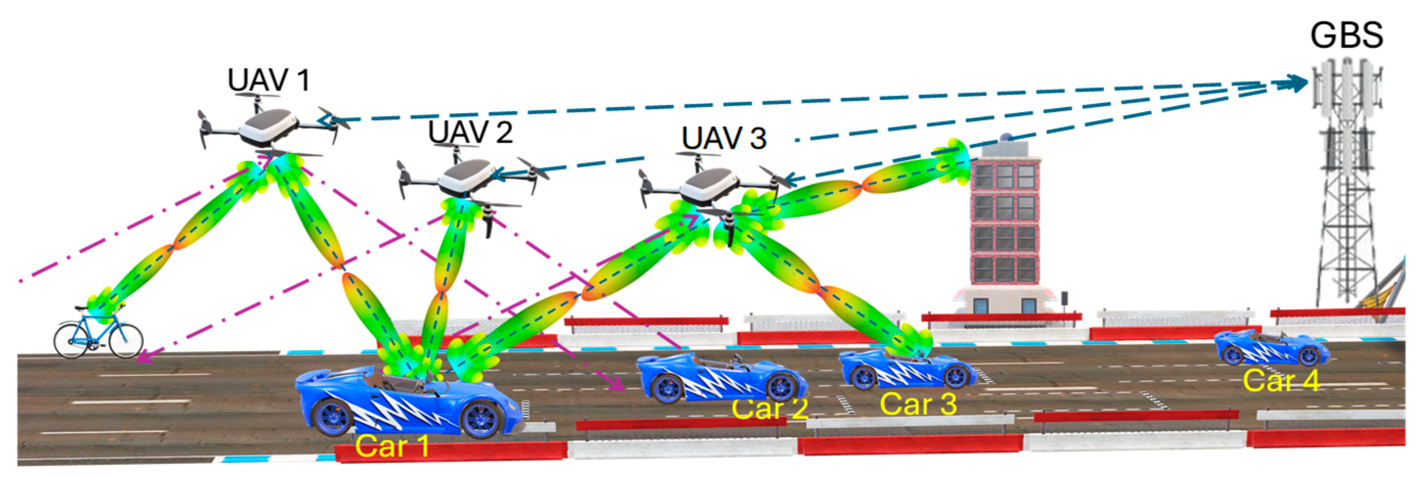
Figure 1 shows the proposed system model of UAV-assisted vehicular communications using the mmWave band. In this scenario, multiple UAVs
,
are deployed as aerial BSs or relays for connecting vehicles to the nearest ground BS (GBS), especially in harsh environments like highways, wilderness, and post-disaster areas. They can also be used to support VANETs such as vehicle-to-vehicle (V2V) communications, as shown in
Figure 1, where UAV 3 is used to relay information from car 1 to car 3 if communication between them fails or is blocked. They can also support vehicle-to-everything (V2I) communications, as shown in
Figure 1, where UAV 1 and UAV 3 relay the communications between car 1 and the roadside bicycles and buildings, respectively. In these cases, vehicle-based optimal UAV selection is of utmost importance. In this scenario, UAV selection aims to optimize the vehicle’s data rate while ensuring an extended coverage duration to minimize the frequency of UAV handovers. Additionally, the UAVs’ restricted energy reserves should be considered, favoring those with greater residual battery levels. The maximization of the achievable data rate necessitates prior mmWave beamforming training between the vehicle and the candidate UAVs covering it, which requires a joint mmWave beamforming and UAV selection optimization process. The challenge in this optimization problem arises from the vehicle’s lack of crucial information about the covering UAVs, such as their flying speeds, altitudes, and positions, which are essential for estimating their coverage durations and adjusting mmWave beams accordingly.
In the rest of this section, we explain the channel models used, the optimization problem formulation, and the fundamentals of OTFS modulation.
3.1. Air-to-Ground Channel Modeling
In the proposed system, two different bands are used. The first one is the wide coverage LTE band, which is used for control and for estimating the UAVs’ parameters using OTFS modulation. The other one is the mmWave band, which is used for data communications.
For the LTE control channel, the extended vehicular A (EVA) channel model, suitable for vehicular communication, is utilized [
31]. The CIR in the delay-time (DT) of EVA is expressed as [
31]:
The total number of paths is represented by
, where
indicates the LoS path, while
is the Dirac delta function. At time
, the complex amplitude of each path
is given by
, coming from the EVA power delay profile, while its Doppler shift and delay spread are given by
and
, respectively. In this context,
in seconds, where
is the separation distance between Tx and Rx, and
is the speed of light. The other delay taps
,
follow the EVA channel model given in [
31].
For
, it comes from the Jakes’ model stated in [
32], where
is calculated as:
where
is the maximum Doppler frequency,
is the relative velocity between the UAV and the vehicle, and
is the operating frequency. At any given time
, the angle of arrival for path
, denoted as
, is assumed to follow a uniform distribution within the interval
as detailed in [
32]. For a comprehensive discussion of the Jakes’ spectrum model, including the derivation processes of the Doppler frequency’s probability density function and the efficiency of the Doppler power spectrum, the reader is referred to Appendix A of [
32].
For mmWave (operating at 60 GHz) channel modeling, we followed the 2D steerable antenna array approach outlined in [
33,
34,
35]. In this model, the power received by an mmWave Rx separated by
meters from an mmWave Tx is expressed as:
Here,
and
denote the Tx and Rx mmWave power in dBm.
represents the path loss over the distance
, while
is the path loss at a reference distance
.
is a constant value obtained from field measurements; in this paper, we followed
stated in [
33] and used in [
34,
35] for 60 GHz mmWave channels. The path loss exponent is denoted as
, while the shadowing component due to log-normal fading is modeled as
which follows a normal distribution with a mean of zero and a standard deviation of
[
34,
35]. The directional beamforming gains for transmission and reception in the 2D plane, expressed in decibels, are represented by
and
respectively. These gains are dependent on the angle of departure
and angle of arrival
. The transmission beamforming gain of the main loop beam,
, can be determined using the formula given in [
34,
35]:
where
is the maximum achievable gain of the antenna in dB,
is the central angle of the Tx beam, and
is the half-power beamwidth. These equations can be similarly applied to evaluate
by substituting
and
by
and
, respectively.
3.2. Optimization Problem Formulation
Suppose that there is a subset of UAVs,
, currently covering a vehicle
. Each UAV
is flying at an altitude
with a flying speed of
m/s at time
, while the vehicle is moving with a speed of
m/s. Also, we assume that both the vehicle and the UAVs are traveling in the x-direction along the highway.
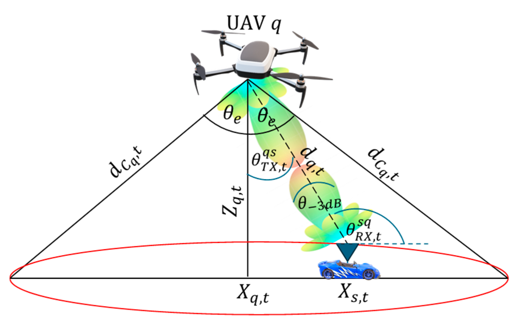
Figure 2 shows the schematic diagram of the vehicle coverage by UAV
. In this figure,
and
represent the x-positions of UAV
and vehicle
at time
,
is their separation distance, and
is the coverage sector angle of UAV
. Both
and
, where
are the central angles of the mmWave Tx and Rx beams from UAV
towards vehicle
and the opposite one, respectively, assuming both beams have the same
value. Also,
represents the coverage distance between UAV
and vehicle
at time
based on
and
. The objective of the optimization problem is to jointly tune
and
and then select the optimal UAV
from
that maximizes the achievable data rate of vehicle
,
. This should be done while guaranteeing a long coverage period
to prevent frequent UAVs handovers constrained by the remaining UAVs’ energies, as follows:
s.t.
- (1)
- (2)
- (3)
- (4)
- (5)
- (6)
where
where
and
represent the available bandwidth and the noise power.
is the received power at the vehicle from UAV
at time
as a function of
and
, as given in Equation (3).
The bound on
is determined by the 2nd constraint in Equation (7) and can be expressed as:
Using
and
, Equation (9) can be re-formulated as:
where the difference between the x-positions of UAV
and the vehicle
is represented by
. Thus,
is upper bounded by:
If both UAV and the vehicle start from the same x-position, then , and should be satisfied.
The 1st constraint in Equation (7) indicates that
should lie between its minimum and maximum values, i.e.,
and
, respectively. In this regard,
is based on the manufacturer, while
corresponds to the average coverage distance
, i.e.,
, which comes from the maximum allowable path loss
using (4), i.e.,
. The 2nd constraint in Equation (7) means that the vehicle should be within the coverage of UAV
. The 3rd and 4th constraints mean that the UAV speed and the vehicle speed should be less than their maximum speeds,
and
. The 5th constraint indicates that both
and
should be less than or equal to
. Finally, the 6th constraint means that the UAV energy consumed for covering the vehicle is bounded by its remaining battery budget,
, where
is written as:
Here, the powers for flying, hovering, and communication of UAV are represented by , and , respectively.
3.3. OTFS Modulation/Demodulation
A review of OTFS modulation and demodulation is provided in this subsection. As depicted in
Figure 3, the OTFS fundamental block diagram organizes complex modulation symbols, such as QAM symbols,
, into a two-dimensional matrix with dimensions
. Here,
and
correspond to the delay and Doppler axes within the DD grid, respectively. The OTFS symbol spans a time duration of
sec and occupies a bandwidth of
Hz. The variables
and
, where
, denote the symbol duration and the modulation and demodulation subcarrier spacing, respectively. In this context,
and
are the Doppler and delay resolutions. The following sub-sections delve into the mathematical aspects of the OTFS.
3.3.1. OTFS Modulation Process
In the OTFS modulation scheme, shown in
Figure 3, the inverse symplectic Fourier transform (ISFFT) is utilized to shift
from the DD domain to the FT domain
. This process involves implementing an FFT on the delay component and an IFFT on the Doppler component, as detailed in [
8].
Subsequently, the one-dimensional DT Tx signal
is constructed using the Heisenberg transform (illustrated in
Figure 3) by applying
as a windowing function [
8]:
3.3.2. Delay-Doppler CIR
The DD channel
is defined as:
In this expression,
indicates the continuous delay while
represents the continuous Doppler shift, where
,
,
, and
are defined in Equation (1). Since our focus is on a single OTFS symbol duration, the subscript
is omitted in Equation (15). The discrete version of the DD channel is expressed as:
Here,
and
are the normalized delay and Doppler indices related to
and
, specified as:
In this framework, the maximum indices and resemble (i.e., the maximum delay spread) and (i.e., the maximum Doppler shift), as outlined in Equation (17).
3.3.3. OTFS Demodulation Process
The received signal
in the DT domain, depicted in
Figure 3, is represented as [
8]:
where
represents AWGN, modeled as a Gaussian random variable with mean zero and standard deviation
. To invert the ISFFT operation performed at the transmitter, a received pulse
is used by Wigner transform to convert
back to the FT domain, as follows [
8]:
The discrete representation of
is obtained by sampling at
and
, resulting in
in the FT domain [
8]:
According to [
10], the relationship between
and
in the FT domain is given by:
Here, the FT-sampled AWGN is represented by
, and
denotes the FT channel response, calculated as [
10]:
To reconstruct the received signal in the DD domain,
, SFFT is applied to
, as follows [
8]:
The final relationship between the transmitted signal
and the received signal
in the DD domain can be established by substituting Equations (13) and (22) into Equation (21) and then into Equation (23), assuming bi-orthogonal pulses [
8]:
where
and
represent the AWGN and the windowed CIR in the DD domain, and
is defined as [
10]:
As described in [
10],
can be interpreted as the circular convolution between the DD CIR and
, which is the SFFT of a rectangular window function:
4. Proposed Joint MmWave Beamforming and UAV Selection
In this section, an out-band OTFS modulation, using the LTE band, is proposed for enabling the vehicle to jointly adjust the Tx and Rx mmWave beams and select the best UAV that maximizes Equation (7). Utilizing the DD CIR information, the vehicle can estimate the subgroup of UAVs,
that can cover it at time
, in addition to the upper bound of their coverage period
for
. It can also estimate the positions of these UAVs and then adjust their mmWave Tx/Rx beams accordingly. To achieve this, the vehicle estimates the DD LTE channel parameters, i.e.,
and
. This estimation can be performed using the method described in [
11]. This method involves using pilot-aided techniques for DD channel estimation. Pilot, guard, and data symbols are strategically positioned in the DD grid of each OTFS frame to manage both integer and fractional Doppler shifts. In the Tx DD grid, only a single pilot is transmitted, surrounded by guard symbols, which is spread across the received DD grid owing to its circular convolution with CIR in the DD domain. Using signal-to-noise ratio (SNR) thresholding, paths at specific
and
values are identified. If the SNR is higher than the specified threshold, a path is identified in its corresponding
and
values, and its channel gain
is estimated accordingly. By estimating
and
for
, the vehicle can estimate their corresponding
and
using Equation (17). Based on the values of
and
, the vehicle can compute both its relative speed to UAV
, denoted as
, and the UAV’s actual velocity
, as described below.
If
, then the vehicle will set
. Then, the x-positions of all UAVs can be estimated utilizing
as follows:
The estimation of
enables the vehicle to estimate
, as given in
Figure 2, as follows:
Then,
can be estimated as:
After estimating
, the vehicle can enumerate the subset
, satisfying the 2nd constraint in (7), as follows:
where
is the estimated coverage distance between UAV
and vehicle
at time
.
Once
is identified, the maximum coverage duration for each UAV is estimated using (11), under the assumption that all UAVs initiate horizontal flight from the same x-position when the vehicle enters their coverage area, as follows:
As stated by the 6th constraint in Equation (7), the actual coverage period of the UAV
,
, is bounded by its remaining battery budget. Thus,
should be the minimum between
and that provided by
as follows:
After estimating
and
as given in Equations (28) and (30), this information is passed to the mmWave module to adjust its Tx/Rx beam directions, i.e., estimating
and
as follows:
After that, the vehicle tunes its beams towards and measures its corresponding as given in Equation (8), and then it selects the UAV that maximizes the product of , which is the objective of Equation (7).
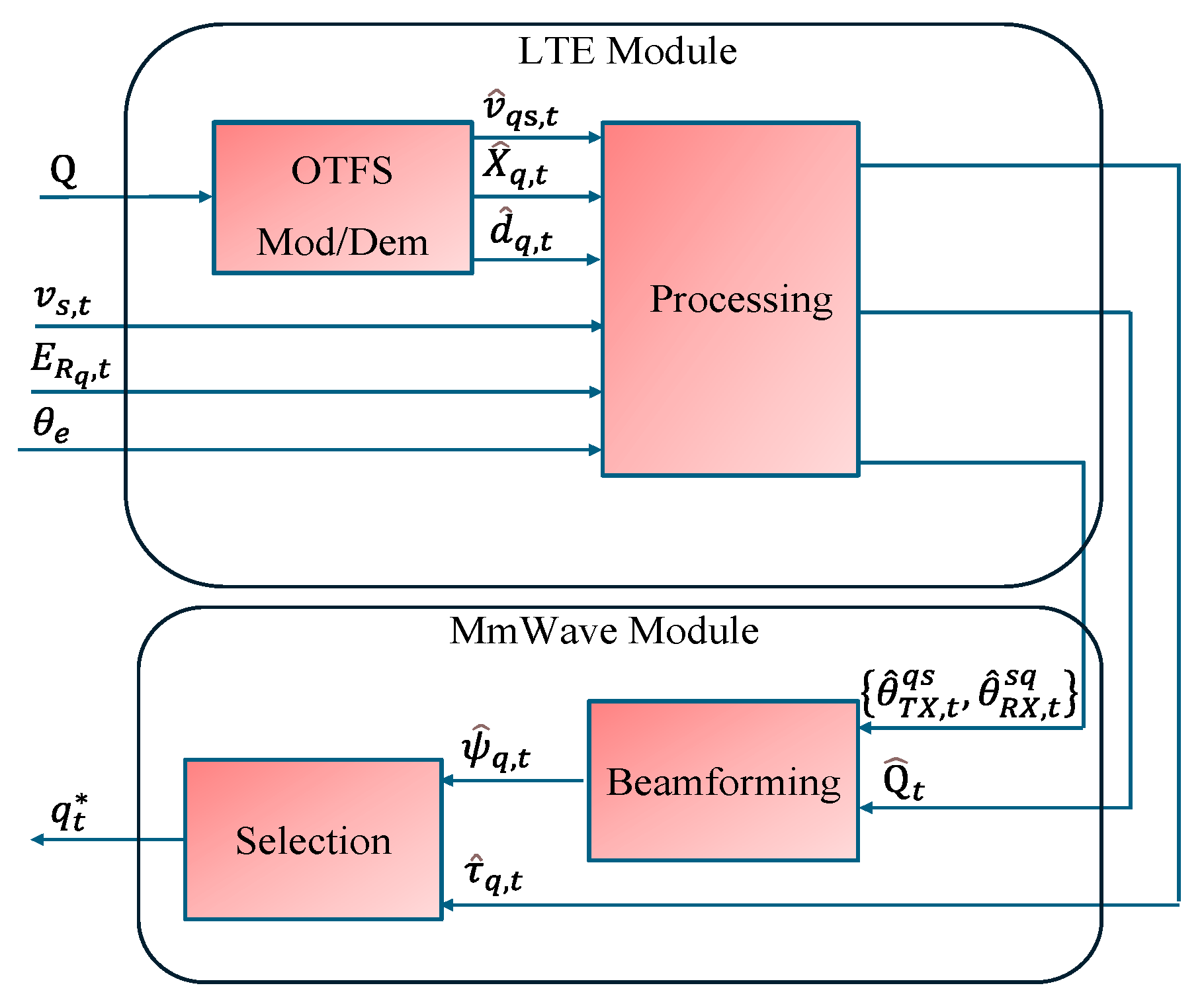
Figure 4 shows the proposed block diagram of the interplay between the LTE and mmWave modules using OTFS modulation/demodulation for joint beamforming and UAV selection. Also, Algorithm 1 summarizes the proposed scheme, which is operated by the vehicle. The inputs to the algorithm are
,
,
,
,
, and
, and the output is the best UAV
at time
.
For the LTE band processing: (1) OTFS mod/demod is applied on the set of
UAVs to estimate their associated
and
using Equation (17) by estimating
and
, as shown in
Figure 4. (2) Then,
and
are processed to evaluate
and
using Equations (27) and (28). Also,
and
are evaluated using Equations (29)–(31) to enumerate
, and then
and
are evaluated using Equations (32) and (33). Finally,
and
are calculated using Equation (34).
For the mmWave band processing: After evaluating
and
, mmWave beamforming is performed between the vehicle and UAVs
, and their
are measured. Then, the best UAV
among
is selected, as given in Algorithm 1 and illustrated in
Figure 4.
To support real-time processing and seamless interplay between LTE and mmWave bands given in
Figure 4, the proposed architecture can be efficiently realized on a hybrid field-programmable gate array–system-on-chip (FPGA–SoC) platform, such as the Xilinx Zynq UltraScale + multiprocessor system-on-chip (MPSoC) [
36]. The OTFS Mod/Dem module is implemented using high-throughput FFT/IFFT intellectual property (IP) cores for the ISFFT and SFFT stages, while custom logic blocks are used for the Heisenberg and Wigner transforms to facilitate domain conversion. The LTE control link is managed by the embedded advanced RISC machine Cortex-A53 (ARM Cortex-A53) processors [
37], which perform UAV selection, mobility estimation, and resource scheduling. These control decisions are relayed to the processing logic via advanced extensible interface (AXI) interconnects. For mmWave communication, beamforming is implemented using digitally controlled radio frequency (RF) front ends and phased antenna arrays, with the beamforming weights computed in the programmable logic and interfaced through high-speed serializer/deserializer (SERDES) channels. Coordination between LTE-assisted control and mmWave data transmission is achieved through efficient direct memory access (DMA)-based data movement and tightly coupled logic, ensuring low-latency handoff and beam alignment. This architecture ensures flexibility, parallelism, and scalability, making it suitable for dynamic vehicular environments and future 6G multi-band communication scenarios involving UAV relays.
| Algorithm 1: Out-band OTFS-based Joint mmWave beamforming and UAV Selection |
Output:
Input: , , , , , and
Using LTE Band
Estimate: and using Equation (17) by estimating and
Evaluate: using Equation (27)
If ,
End If
Evaluate: using (28)
Evaluate: and using Equations (29)–(31).
If , q
End If
Evaluate: and using Equations (32) and (33)
Evaluate: and using Equation (34)
Using MmWave Band
Beamforming: with all using and and measure their corresponding
Select: the best UAV from
End |
Since this paper primarily focuses on joint mmWave and UAV selection based on DD channel information, DD-enabled UAV trajectory planning is considered beyond the current scope and is left for future work, following the approach in [
38].
5. Numerical Analysis
A comprehensive numerical evaluation is conducted to assess the performance of the proposed method across diverse scenarios. In these experiments, multiple UAVs are randomly positioned at varying flying altitudes within the range
, where
and
, aligned with a maximum path loss
of 120 dB. The UAVs operate at different speeds, randomly selected from the interval
km/h. Additionally,
,
, and
, respectively, with
. Unless explicitly noted, other simulation configurations are detailed in
Table 1. For benchmarking, the proposed strategy is evaluated against the exhaustive search approach, where the vehicle performs complete beamforming training with every potential UAV and then selects the one providing the maximum received power as well as the best Tx/Rx mmWave beams. Also, a random selection approach is considered, where the vehicle randomly selects a UAV from the candidate UAVs and then conducts exhaustive search beamforming training with it to find the best Tx/Rx mmWave beams. For performance assessment, we measure the average data rate provided by a UAV to the vehicle
in Gbps, its average coverage period
in sec, and its average transmitted data
in Gbits. Additionally, we assess the average energy efficiency
in GbpJ.
5.1. Impact of the Number of UAVs
In the following simulation results, the evaluated schemes are compared by varying the number of UAVs, while maintaining the vehicle’s speed constant at 120 km/h. It is assumed that the DD channel parameters are perfectly estimated, such that
, and
,
.
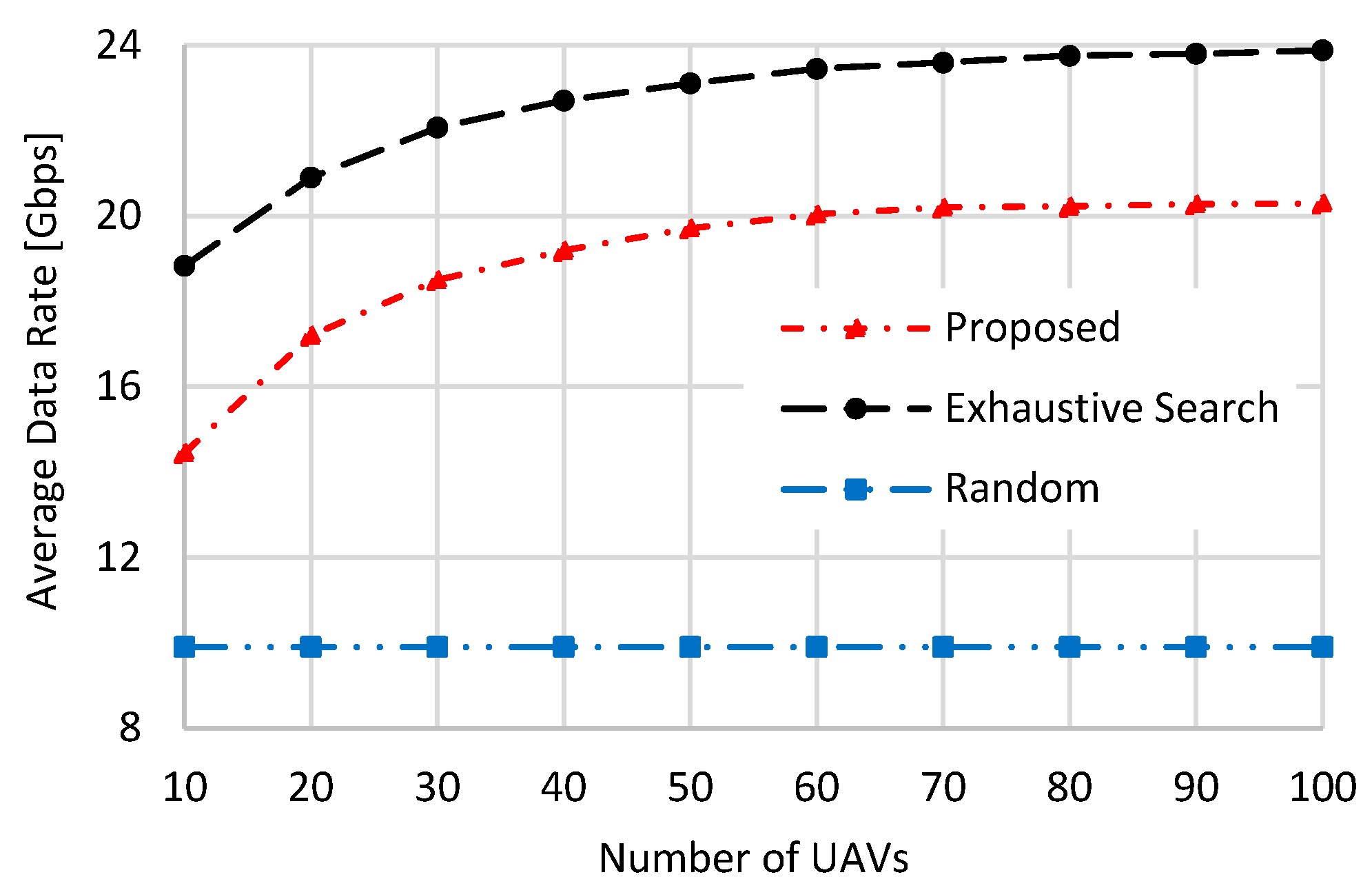
Figure 5,
Figure 6,
Figure 7 and
Figure 8 illustrate the comparative metrics of the studied schemes, including
,
,
, and
, respectively.
As illustrated in
Figure 5, both the proposed scheme and the exhaustive search approach demonstrate an improvement in average data rate as the number of UAVs increases. This trend is attributed to the greater probability of selecting a UAV offering superior channel conditions when more UAVs are present, thereby enhancing the received signal strength and consequently boosting the data rate. The exhaustive search approach consistently achieves the highest average data rate, since its selection criterion focuses solely on maximizing the received power, which directly correlates with higher data rates. In contrast, the proposed scheme aims to optimize the product of
, as formulated in the objective of Equation (7), prioritizing both data rate and coverage duration. Meanwhile, the “Random” selection strategy maintains a nearly fixed average data rate regardless of the number of UAVs, as its UAV selection process is entirely random. When the number of UAVs is set to 10, the average data rate of the proposed and the “Random” selection schemes reaches about 76.78% and 52.6% of the exhaustive search, respectively. These values become 85% and 41.46%, respectively, when the number of UAVs is set to 100.
Figure 6 illustrates how the average vehicle’s coverage duration varies with different numbers of UAVs deployed. The proposed approach achieves superior performance, with the coverage period extending as the UAV count grows. This improvement stems from the scheme’s objective to jointly optimize both the data rate and the coverage duration. Additionally, the increase in UAV density enhances the likelihood of selecting a UAV capable of providing a longer and more stable coverage period. The “Random” selection scheme has a fixed coverage period performance due to the random choice of UAV. It is interesting to note that the exhaustive search scheme exhibits the lowest coverage period performance, and is even lower than the “Random” selection scheme. This is because the exhaustive search mechanism selects the UAV with the maximum received power, which typically flies at the lowest altitude and therefore has the lowest
, as given in Equation (32). Moreover, this coverage period decreases further as the number of UAVs increases due to the higher chance of finding a UAV with stronger received power at a lower altitude and, consequently, a lower
. From
Figure 6, the proposed scheme achieves a higher average coverage period than the “Random” selection and exhaustive search schemes by 1.55 and 4.23 times, respectively, when the number of UAVs is set to 10. These values become 1.81 and 14.89 when the number of UAVs is set to 100.
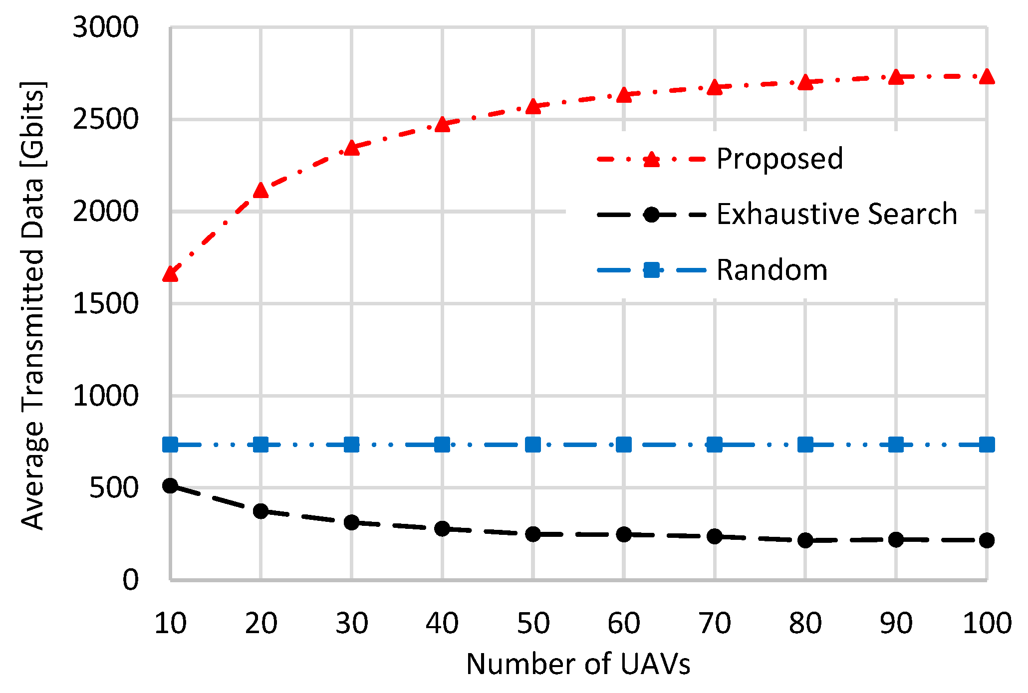
Figure 7 presents the average volume of transmitted data in Gbits, reflecting the objective of Equation (7). The proposed method consistently outperforms the other two schemes, with its advantage becoming more evident as the number of UAVs rises. This behavior aligns with the data rate and coverage duration trends illustrated in
Figure 5 and
Figure 6, where the increased availability of UAVs leads to higher average transmitted data under the proposed approach. Conversely, the “Random” scheme maintains a fixed amount of transmitted data irrespective of UAV density, a consequence of its limited data rate and coverage period performance, as previously shown in
Figure 5 and
Figure 6. For the exhaustive search scheme, increasing the number of UAVs leads to lower transmitted data performance, as it is strongly affected by the significant decrease in its coverage period performance (
Figure 6), which outweighs its data rate performance (
Figure 5). From
Figure 7, the proposed scheme achieves higher average transmitted data than the “Random” selection and exhaustive search schemes by 2.26 and 3.25 times, respectively, when the number of UAVs is set to 10. These values become 3.72 and 12.68 when the number of UAVs is set to 100.
Figure 8 illustrates the average energy efficiency in GbpJ of the evaluated schemes. The proposed approach achieves the highest energy efficiency due to its consideration of UAVs’ remaining battery capacities during the selection process. Furthermore, its efficiency improves as more UAVs are introduced, benefiting from the enhanced data transmission performance shown in
Figure 7. In contrast, the exhaustive search method delivers the lowest energy efficiency, which further deteriorates as the number of UAVs increases. This decline is attributed to two factors: firstly, its data transmission volume decreases with UAV density (
Figure 7); secondly, it ignores the UAVs’ battery status during selection. Similarly, the “Random” selection method maintains a steady energy efficiency regardless of UAV count, reflecting its static transmitted data performance shown in
Figure 7. Overall, the proposed scheme outperforms the “Random” and exhaustive search strategies by factors of approximately 1.127 and 1.28, respectively, when 10 UAVs are deployed, and these margins increase to about 1.237 and 2.59 when the UAV count reaches 100.
5.2. Impact of the Vehicle Speed
In the following numerical analysis,
,
,
, and
of the compared schemes are investigated while varying the vehicle’s speed using 50 UAVs and assuming perfect DD channel estimation.
Figure 9,
Figure 10,
Figure 11 and
Figure 12 show the results of these simulations.
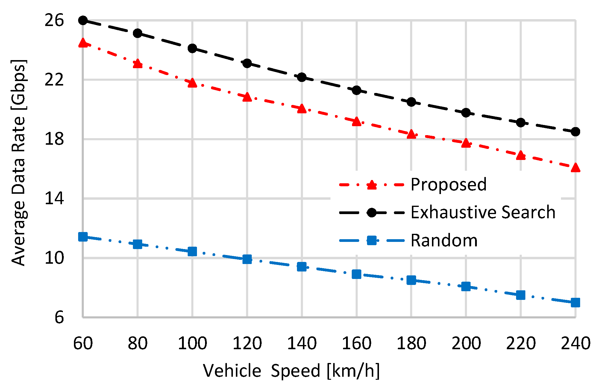
From
Figure 9, as the vehicle’s speed increases, the average data rate of all compared schemes steadily decreases. This results from the high relative speed between the vehicle and the UAVs, which increases the Doppler shift and consequently reduces the channel gain. The exhaustive search shows the best performance due to its selection of the UAV that maximizes the received power. The proposed scheme shows lower average data rate performance than the exhaustive search, as it maximizes both the data rate and the coverage period. The worst performance belongs to the “Random” selection scheme, as the UAV is randomly selected. From
Figure 9, the exhaustive search has a higher average data rate performance than the proposed and the “Random” schemes by 1.06 and 2.27 times, respectively, when the vehicle speed is set to 60 km/h. These values become 1.11 and 2.57 when the vehicle speed is set to 240 km/h.
From
Figure 10, an increase in the vehicle’s speed decreases the average vehicle coverage period of all compared schemes. This is because the coverage period is inversely proportional to the vehicle’s speed, as given in Equation (11). The proposed scheme has the best coverage period performance, as it maximizes coverage in addition to the achievable data rate. The exhaustive search has the lowest coverage period performance due to the reasoning given when analyzing
Figure 6. The “Random” selection has better coverage period performance than the exhaustive search scheme due to its random UAV selection. From
Figure 10, the proposed scheme has a higher average coverage period than the exhaustive search and the “Random” schemes by 3.89 and 1.5 times, respectively, when the vehicle speed is set to 60 km/h, and these values become 18.72 and 1.84 when the vehicle’s speed is set to 240 km/h.
Influenced by both data rate and coverage period performances, the average transmitted data of the compared schemes decreases as the vehicle’s speed increases, as shown in
Figure 11. The best performance belongs to the proposed scheme, while the worst belongs to the exhaustive search, affected by its lowest coverage period performance, given in
Figure 10. From
Figure 11, when the vehicle’s speed is set to 60 km/h, the proposed scheme has a higher average transmitted data performance than the exhaustive search and the “Random” schemes by 3.67 and 3.2 times, respectively. These values become 16.32 and 4.24 when vehicle speed is 240 km/h.
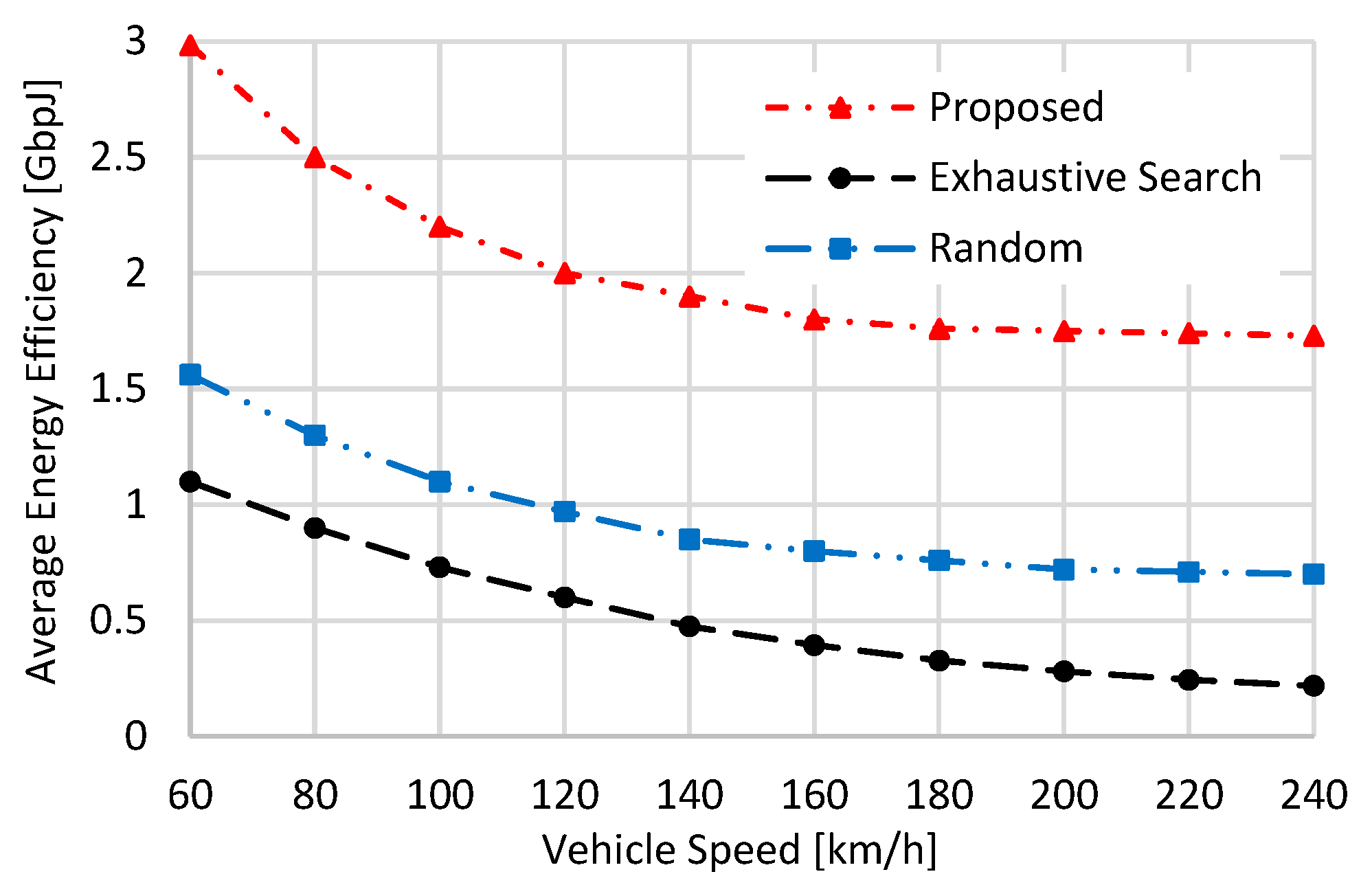
From
Figure 12, when the vehicle’s speed increases, the average energy efficiency of all schemes decreases due to the reduction in transmitted data caused by poor channel conditions owing to the increased Doppler shift. As the proposed scheme considers the UAVs’ remaining battery capacities when selecting the best one, it has the best average energy efficiency performance. The exhaustive search scheme has the lowest performance, attributed to its lowest transmitted data performance given in
Figure 11. From
Figure 12, the proposed scheme has a higher average energy efficiency performance than the exhaustive search and the “Random” schemes by 2.71 and 1.91 times, respectively, when the vehicle’s speed is set to 60 km/h. When the vehicle’s speed is set to 240 km/h, these values become 7.9 and 2.47.
5.3. Impact of DD Channel Estimation Error on the Performance of the Proposed Scheme
In the following numerical simulations, the performance of the proposed scheme is investigated under DD channel estimation error for different vehicle speeds while fixing the UAV speed to 60 km/h. To model the channel estimation error, we follow [
39], where
and
can be expressed as [
39]:
where
is a normal random variable with a 0 mean and a standard deviation of
. Similarly,
, but with a standard deviation of
.
Figure 13 and
Figure 14 illustrate the losses in the transmitted data and energy efficiency of the proposed scheme versus
, which represent the normalized DD channel estimation error. In these figures,
and
vary from 0 to 100%, where 0 indicates perfect channel estimation. Different vehicle speeds
are also tested, using a fleet of 50 UAVs flying at a constant speed of 60 km/h. When both
σα/
α(1,t) and
σβ/
βmax are equal to 0, which corresponds to perfect channel estimation, the performance losses are equal to 0. As
increase, the performance of the proposed scheme declines, causing significant losses, as given in both figures. This results from the high estimation errors in Doppler shifts and LoS path attenuations, which strongly affect the estimation of UAV speeds, positions, and altitudes. Consequently, coverage periods and mmWave Tx/Rx beam directions are estimated incorrectly, preventing the vehicle from selecting the UAV that maximizes the objective in Equation (7), and the performance losses of the proposed scheme increase significantly. Additionally, as the ratio between
and
increases, the loss rate rises sharply. This is due to the higher Doppler shifts and LoS attenuation caused by the increased relative speed between UAVs and the vehicle. For example, when the speed ratio is set to 2, corresponding to
, the proposed scheme experiences losses of 20% in transmitted data and 37% in energy efficiency. These losses become more severe as the speed gap widens. At a ratio of 3 (
), the data and energy efficiency losses rise to 31% and 57%, respectively. When the ratio reaches 4 (
), the losses further increase to 33% in transmitted data and 60% in energy efficiency.
To overcome this channel estimation error, we propose using mmWave beamforming training. That is, instead of only using the estimated Tx/Rx beam directions, i.e.,
and
, for establishing the mmWave communication between the vehicle and the UAVs, we use multiple beams with angles
and
around
and
. In this context,
is expressed as:
where the total number of beams is equal to
, and the same equation is applied for
using
instead of
. Thus, exhaustive search beamforming training is conducted using
and
for all candidate UAVs
. Then, the Tx/Rx beam pairs with the highest received power are selected for establishing the mmWave communication links between the vehicle and UAVs, and the UAV maximizing the objective function of Equation (7) is selected by the vehicle. In this way, we can overcome the error in estimating UAVs’ speeds and hence their positions and altitudes by scanning the region around the estimated UAV position using multiple mmWave beams.
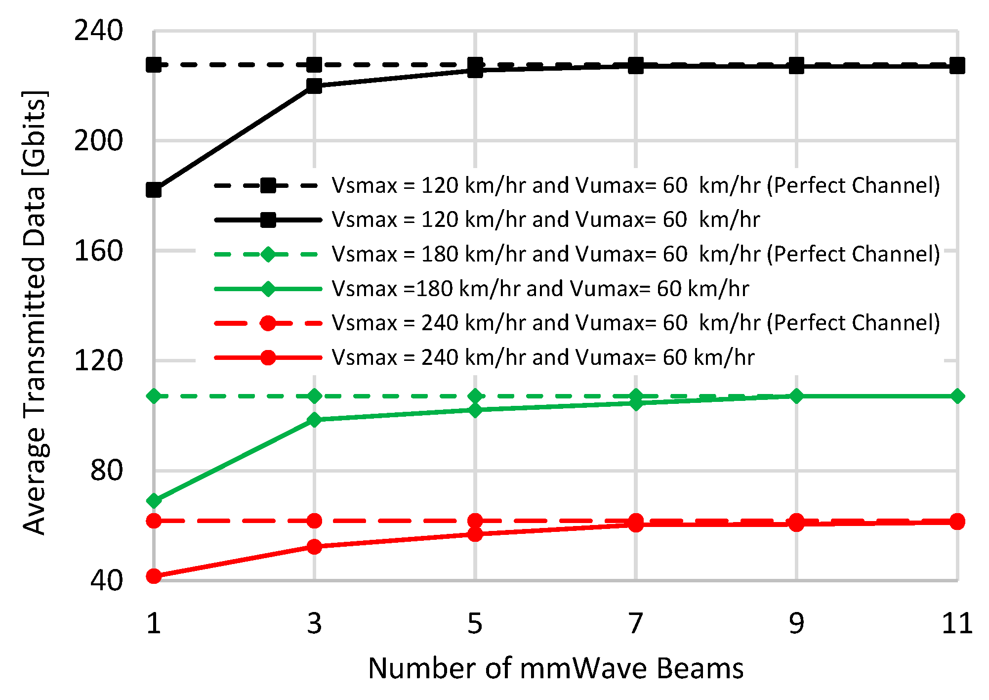
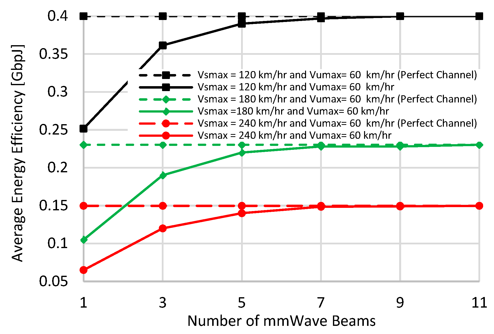
Figure 15 and
Figure 16 give the average data and the energy efficiency of the proposed scheme against the number of Tx/Rx beams used in the exhaustive search beamforming training. Also, a normalized channel estimation error of 100%, i.e.,
, is considered. As the number of beams increases, the performance of the proposed scheme is greatly enhanced and reaches perfect channel performance, i.e., without any estimation error. From both figures, only five Tx and Rx beams are enough to nearly reach perfect channel performance for all tested speeds.
5.4. Complexity Analysis
The proposed approach consists of two stages. In the LTE stage, the vehicle communicates with UAVs using LTE band for estimating their DD channel parameters, speeds, and positions with a complexity of . In the second mmWave stage, the vehicle communicates with UAVs using mmWave beamforming with a complexity of . If beamforming training is needed to overcome channel estimation error using beams, the complexity becomes . Thus, the complexity of the proposed scheme will be . For the exhaustive search scheme, its complexity comes from conducting exhaustive search beamforming training with all UAVs in the mmWave band with a total number of beams of . Thus its complexity is which is extremely high. For the “Random” scheme, its complexity comes from selecting one UAV at random and executing mmWave exhaustive beamforming training with it, with a complexity of . As and , we can conclude that the proposed scheme has lower computational complexity than exhaustive search while achieving the best performance.
6. Conclusions
In this paper, we studied the joint problem of mmWave beamforming training and UAV selection for UAV-assisted vehicular communication. We formulated an optimization framework that selects the most suitable UAV to maximize the vehicle’s achievable data rate and its coverage duration while accounting for residual UAV battery life. Unlike prior works where dynamic features like UAV speeds, flight altitudes, and remaining energy were not considered, our approach leverages DD channel parameters by means of OTFS modulation to estimate these parameters. These estimates facilitate efficient mmWave beam alignment and informed UAV selection. Extensive numerical analysis showed the superior performance of the proposed scheme over other benchmarks in terms of achievable data rate, vehicle coverage duration, transmitted data, and energy efficiency under varying numbers of UAVs and vehicle speeds. The results revealed that the proposed scheme has higher average energy efficiency than the random and exhaustive search schemes by 1.237 and 2.59 times, respectively, when the number of UAVs is set to 100 with a fixed vehicle speed of 120 km/h. It also has better energy efficiency than both by 7.9 and 2.47 times when the vehicle speed is set to 240 km/h using a fleet of 50 UAVs. Additionally, we investigated the effect of DD channel estimation error on the performance of the proposed scheme. The results revealed that when the speed ratio between UAVs and the ground vehicle is set to 2, 3, and 4, the losses in energy efficiency increase by 37%, 57%, and 60%, respectively. Finally, we showed that a limited beamforming training with only a few beams can efficiently overcome this error.
