Article

Dynamic Resource Target Assignment Problem for Laser Systems’ Defense Against Malicious UAV Swarms Based on MADDPG-IA

1
Air and Missile Defense College, Air Force Engineering University, Xi’an 710051, China
2
Unit of 95972, Chinese People’s Liberation Army, Jiuquan 735000, China
*
Author to whom correspondence should be addressed.
Aerospace 2025, 12(8), 729; https://doi.org/10.3390/aerospace12080729
Submission received: 14 July 2025 / Revised: 12 August 2025 / Accepted: 15 August 2025 / Published: 17 August 2025

Abstract

The widespread adoption of Unmanned Aerial Vehicles (UAVs) in civilian domains, such as airport security and critical infrastructure protection, has introduced significant safety risks that necessitate effective countermeasures. High-Energy Laser Systems (HELSs) offer a promising defensive solution; however, when confronting large-scale malicious UAV swarms, the Dynamic Resource Target Assignment (DRTA) problem becomes critical. To address the challenges of complex combinatorial optimization problems, a method combining precise physical models with multi-agent reinforcement learning (MARL) is proposed. Firstly, an environment-dependent HELS damage model was developed. This model integrates atmospheric transmission effects and thermal effects to precisely quantify the required irradiation time to achieve the desired damage effect on a target. This forms the foundation of the HELS–UAV–DRTA model, which employs a two-stage dynamic assignment structure designed to maximize the target priority and defense benefit. An innovative MADDPG-IA (I: intrinsic reward, and A: attention mechanism) algorithm is proposed to meet the MARL challenges in the HELS–UAV–DRTA problem: an attention mechanism compresses variable-length target states into fixed-size encodings, while a Random Network Distillation (RND)-based intrinsic reward module delivers dense rewards that alleviate the extreme reward sparsity. Large-scale scenario simulations (100 independent runs per scenario) involving 50 UAVs and 5 HELS across diverse environments demonstrate the method’s superiority, achieving mean damage rates of 99.65% ± 0.32% vs. 72.64% ± 3.21% (rural), 79.37% ± 2.15% vs. 51.29% ± 4.87% (desert), and 91.25% ± 1.78% vs. 67.38% ± 3.95% (coastal). The method autonomously evolved effective strategies such as delaying decision-making to await the optimal timing and cross-region coordination. The ablation and comparison experiments further confirm MADDPG-IA’s superior convergence, stability, and exploration capabilities. This work bridges the gap between complex mathematical and physical mechanisms and real-time collaborative decision optimization. It provides an innovative theoretical and methodological basis for public-security applications.

1. Introduction

Rapid advances in unmanned aerial vehicle (UAV) technology have expanded its applications across diverse civilian domains, including logistics, surveying and mapping, and agriculture [1]. However, the misuse or malfunction of UAVs also poses substantial threats to public safety. This is particularly critical in sensitive areas such as airport clear zone security, the protection of critical infrastructure (e.g., power plants and oil depots), security for large-scale public events, and border surveillance. Unauthorized or malicious UAV operations in these contexts can potentially lead to severe consequences. Consequently, there is a pressing practical need to develop efficient and reliable UAV defense systems [2]. High-Energy Laser Systems (HELSs) are considered a promising technological solution for addressing such threats due to their inherent advantages: light-speed damage capability, high precision, and low cost-per-shot. However, existing HELS-based defensive approaches face formidable challenges when confronted with large-scale, highly dynamic UAV swarm incursions. The core challenge is to intelligently and dynamically assign limited HELS resources (including the number of available systems, and their energy reserves) to a multitude of rapidly moving targets in real time to maximize overall defensive effectiveness.
The Dynamic Resource Target Assignment (DRTA) is a complex combinatorial optimization problem, mainly focusing on how to assign targets to various defense units in a planning manner, to optimally achieve the defense intention [3,4,5]. However, the unique characteristics of HELS defense UAV swarm scenarios introduce significant complexities: (1) Individual HELSs possess inherent limitations in the damage range. Consequently, multi-HELS networks are essential for an effective coverage against a low-altitude UAV swarm. This networked deployment drastically alters key parameters like spatial relationships, effective defense capability, and resource utilization efficiency, complicating the formulation of generalized allocation rules [6]. (2) Countering large-scale UAV swarms operating at low altitudes and close ranges, and from multiple directions creates a highly uncertain environment. Assessing the target priority and countermeasure value becomes exceptionally challenging for both homogeneous and heterogeneous UAV swarms, making prioritization strategies difficult to define [7]. (3) The near-instantaneous effect capability of HELSs enables multiple decisions within short timeframes. A real-time, asynchronous assignment that is responsive to the dynamic state of each HELS unit is essential [8]. (4) The damage efficacy of HELSs diminishes significantly with distance, making long-range damage resource-intensive and inefficient. While delaying defense until targets are closer improves individual damage speed, this strategy carries risk: during the delay period, other targets may enter the protect zone, or existing targets may depart, increasing the overall system vulnerability. Dynamic decision-making, continuously balancing efficacy and opportunity, is required [9].
In the existing research, there are abundant achievements in the modeling methods for the dynamic target assignment problem, which mostly employs modeling approaches such as mathematical programming, game theory, graph theory, and dynamic programming for rule description [10,11,12], providing methods and ideas for solving the complex combinatorial optimization problem. For example, Hanáket et al. [13] proposed a method based on cross-entropy for the HELS assignment problem in various scenarios assuming the large-scale simultaneous firing on protected areas. Taylor [14] investigated the attack formations of UAV swarms, and established a value ranking model for HELSs to damage UAV targets in a swarm threat. Yang and Li [6] established the constraints of interception based on the damage process of HELSs against UAVs, from aspects such as resource constraints, spatiotemporal relationships, and guidance probabilities. Gong et al. [15] established a model for photoelectric systems with multiple tactical targets, considering constraints such as system capabilities, and strategic constraints, based on the combat performance of photoelectric systems. However, due to their high computational complexity, these methods are unable to handle real-time decision-making in dynamic environments, and their work ignores laser degradation caused by weather and assumes that the target assignment is synchronous. Traditional dynamic target assignment methods assume instantaneous interception with fixed resource constraints, while high-energy laser systems (HELSs) introduce unique challenges: (1) continuous irradiation requirements (targets must be irradiated until energy thresholds are met), (2) weather-dependent damage efficiency (atmospheric turbulence and thermal blooming degrade laser beam quality), and (3) asynchronous decision-making (irradiation time varies with target distance and material properties). These constraints render conventional models inadequate for real-time decisions. With the continuous development of technology, large-scale game confrontation will make the environment more complex and fuller of uncertainties. Therefore, studying the DRTA problem of the HELS defense UAV swarm under dynamic and uncertain conditions is a key direction for the development of this field.
Since the DRTA problem belongs to a nonlinear combinatorial optimization problem, as the number of targets increases, it will cause a slow solution speed [16,17,18]. Traditional intelligent optimization algorithms, such as the particle swarm optimization (PSO) algorithm [6], artificial bee colony (ABC) algorithm [19], multi-objective evolution algorithm (MOEA) [15], etc., expose problems such as the slow convergence speed and the large number of iterative operations when facing complex decision-making scenarios. It is difficult to meet the decision-making requirements of an efficient and high-quality real-time scene. Furthermore, heuristic algorithms based on rules can be closer to the problem-solving methods of human thinking. Under the premise of the given scenarios and domain knowledge, they can be more efficient than intelligent optimization algorithms. However, there is also the difficulty of generalizing from a part to the whole when establishing rule descriptions that conform to practical problems [11,20]. In recent years, deep reinforcement learning (DRL) has demonstrated strong learning and decision optimization capabilities in issues such as ATARI games and AlphaGo, and has received extensive attention. DRL’s “action-selection” naturally parallels the optimization of discrete decision variables in combinatorial optimization. Its characteristics of “offline training and online decision-making” endow it with the potential to solve combinatorial optimization problems online in real time, and it is currently a better solution method for combinatorial optimization [21]. For example, Liu et al. [22] proposed a general and narrow agent task allocation proximal policy optimization algorithm to solve the ground-to-air confrontation task assignment problem and effectively deal with the solution of a large number of concurrent task assignment and random event problems. Huang et al. [23] proposed a multi-system cooperative anti-UAV method based on the deep Q-network and the optimization of the evolutionary algorithm to generate multiple interception schemes. Hu et al. [24] noticed the dynamic complexity of multiple unmanned ships at sea and developed a solution method based on the multi-agent reinforcement learning (MARL) algorithm. However, due to the different numbers and spatial distributions of unmanned aerial vehicle swarms, existing RL frameworks rely on fixed-length state representations, resulting in information loss or filling noise. The traditional exploration strategy does not work well in the HELS scenario because the reward (target destruction) only appears after prolonged exposure [25,26].
Based on the above discussion, this paper will propose an HELS–UAV–DRTA model and a solution method based on DRL, providing a scientifically sound decision-making tool for real-world HELS deployment. The main contributions are summarized as follows:
(1)
By analyzing the thermal damage mechanism of HELSs and considering the impact of various factors such as spatial situation and weather conditions, we construct an HELS damage-capability model that incorporates atmospheric-transmission and thermal-damage effects. Based on the real-time situation of malicious UAV swarms and the need for defense benefits, an HELS–UAV–DRTA model focused on optimal damage effectiveness has been established. This has further evolved into strategies such as delaying decision-making to await optimal timing and intercepting in different areas in coordination, to optimally achieve the intention.
(2)
To tackle the challenges of dynamically varying state dimensions, sparse extrinsic rewards, and limited resources when solving the HELS–UAV–DRTA problem via DRL, we proposed the MADDPG-IA (Multi-Agent Deep Deterministic Policy Gradient, MADDPG; I: intrinsic reward, and A: attention mechanism) algorithm. An attention-based encoder aggregates variable-length target states into fixed-size representations, while a Random Network Distillation (RND)-based intrinsic reward module provides dense exploration rewards, substantially boosting both performance and practicality.
(3)
Taking the defense problems of small-scale and large-scale UAV swarms as examples, comprehensively considering factors such as the atmospheric environment and swarms’ density, a typical HELS–UAV–DRTA scenario with the background of rural, desert, and coastal regions was established, providing ideas for solving actual problems. Experiments in various scenarios show the effectiveness and applicability of the MADDPG-IA algorithm in solving the HELS–UAV–DRTA problem. Through ablation experiments and algorithm comparison experiments, it is verified that the MADDPG-IA algorithm has significant convergence ability and stability, and has a stronger exploration ability.

2. Modeling the HELS–UAV–DRTA Problem

This section constructs a mathematical model used to describe its decision-making process. Given that the damage range of HELSs is usually only at the kilometer level and the time for UAV swarms to reach the defense area is extremely short, the damage time has become a key indicator for measuring defense effectiveness. Firstly, starting from the damage mechanism of HELSs, through in-depth research on the effects of laser atmospheric transmission and thermal damage, a quantitative model of the damage time of HELSs was constructed. Secondly, taking a malicious UAV swarm as an example, a target flow description method for the swarm patterns is constructed in order to determine its spatial distribution characteristics. On this basis, considering the target threat and defense benefit factors, the HELS–UAV–DRTA model is constructed to achieve the dynamic and optimal assignment of HELS resources. The framework of the model is shown in Figure 1.

2.1. Laser Damage Model: Transmission and Thermal Effects

The damage mechanism of HELSs relies on the thermal effect of lasers. As the laser beam transmitted through the atmosphere and irradiates the target surface, photons are absorbed by the material’s electrons, converting light energy into heat through collisions. This process causes the temperature of the material to rise rapidly from the surface to the interior. When the temperature of a material reaches its melting point or boiling point, melting or even vaporization will occur. During this process, pits will form on the surface of the target, and, in severe cases, penetrations may even occur, thereby damaging the integrity of the target structure and ultimately achieving a destructive effect on the target [27]. Based on the damage mechanism of HELSs, the following are, respectively, constructed—the characteristic model of laser transmission through the atmosphere and the laser thermal damage model—thereby forming a quantitative description of the damage capability of HELSs.

2.1.1. Laser Atmospheric Transmission Model

The most significant constraint on laser transmission in the atmosphere is the Fraunhofer diffraction limit, which determines the size of the laser spot that can be formed at a distance [27]. Ideally, the radius r spot of the far-field laser spot is measured in proportion to the wavelength λ and the aperture D; that is,
r spot = 1.22 λ D L β
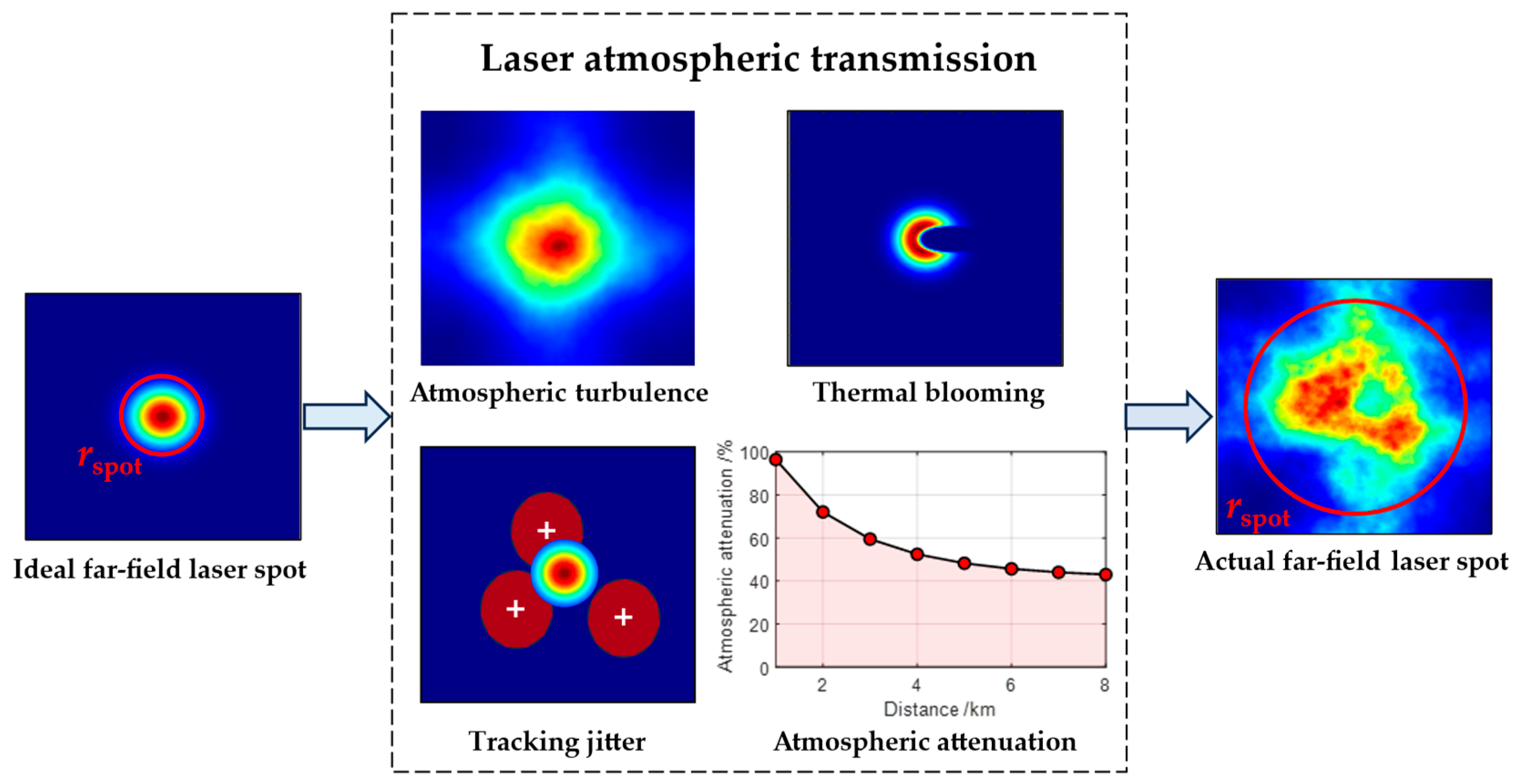
where L represents the transmission distance and β is the beam quality factor, which is used to characterize the beam quality degradation of the laser in the far field after being focused and transmitted through the atmosphere. Due to the existence of atmospheric turbulence effects, thermal blooming effects, and absorption and scattering effects, and when laser is transmitted in the atmosphere, as well as the jitter of the laser itself, each step in the transmission process deteriorates the beam quality, thereby reducing the laser irradiation capacity and causing an expansion of the spot area, as shown in Figure 2.
The calculation method for the far-field light spot of laser after transmission through the atmosphere can be derived from four types of approaches: theoretical analysis, numerical simulation, rapid estimation model, and experimental measurement [27]. Here, a rapid estimation model based on the scaling law model is adopted for calculation, which has met the high dynamics requirement of resource assignment [28]. For the beam expansion at the focal plane, the mean square and radius analysis methods are adopted for calculation. Therefore, the beam quality factor of the laser after atmospheric transmission can be expressed as follows [29]:
β 2 = β 0 2 + β T 2 + β B 2 + β J 2
where β0, βT, βB, and βJ are the beam quality factors characterizing the beam spread caused by atmospheric diffraction, turbulence, thermal blooming effect, and tracking jitter, respectively [28]. The following is an analysis of the above-mentioned influencing factors:
(1)
The influence of atmospheric turbulence on βT
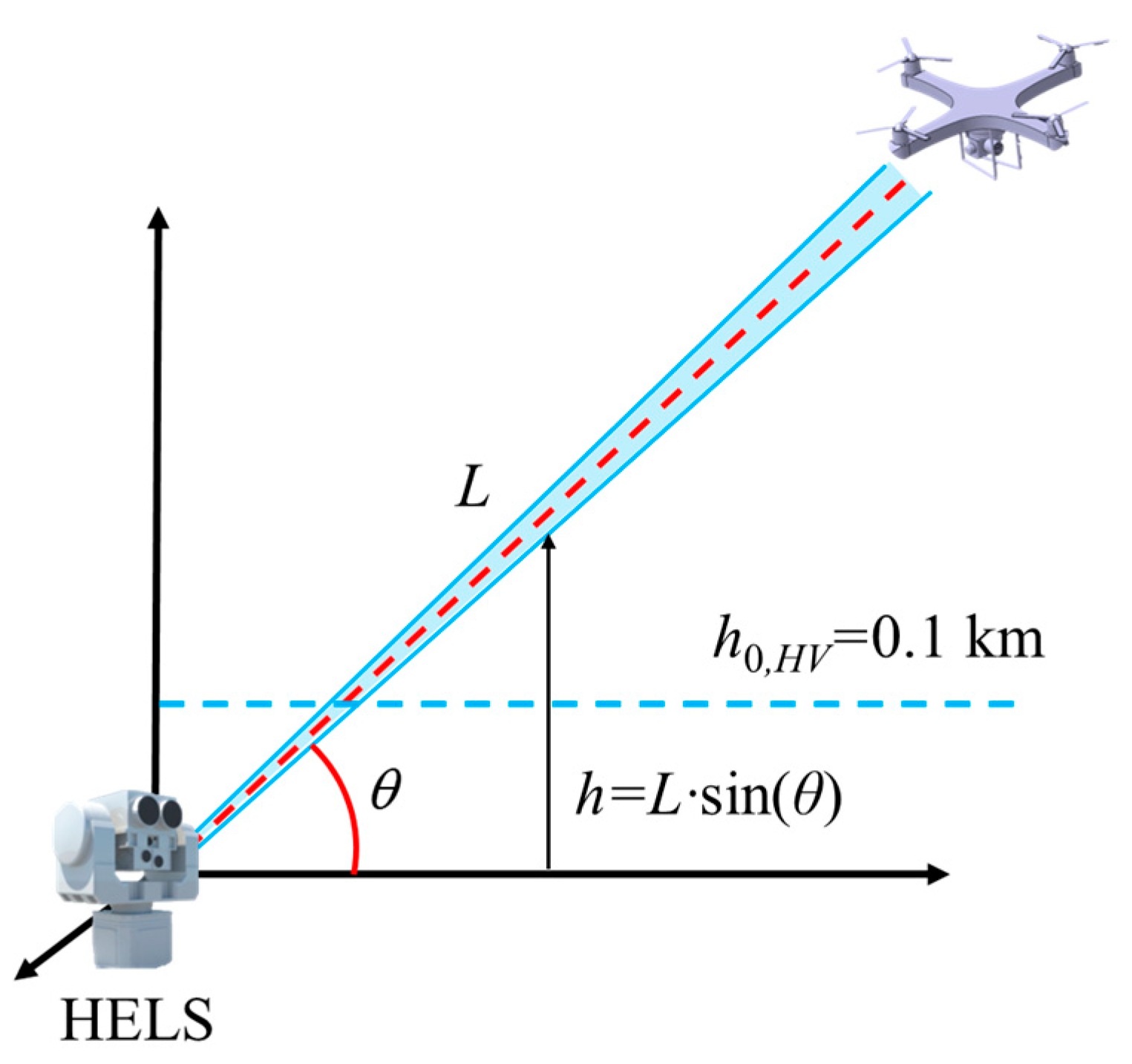
Atmospheric turbulence can cause phenomena such as beam expansion, spot drift, intensity fluctuation, and phase distortion during the transmission of the laser. The level of atmospheric turbulence depends on local meteorological conditions, such as the temperature, air pressure, wind speed, sunshine duration, season, time, height from the ground, topography, etc., and is characterized by the refractive index structure constant C n 2 [30]. Due to the changes in the atmospheric elevation and slant path when HELSs irradiate UAVs, as shown in Figure 3, an appropriate C n 2 model needs to be adopted to describe the atmospheric turbulence situation.
Considering that the Hufnagel–Valley (H–V) model is not only related to height but also introduces adjustable parameters such as wind speed, it is more suitable for the calculation of the scenario where the HELS defends the UAV [31]. Meanwhile, in view of the characteristics of slant atmospheric transmission, when selecting the atmospheric turbulence model, the slant path H–V model for slant correction proposed by Jan and Przemysław [30] is further adopted for calculation; that is,
C n , HV 2 L C n 2 h exp L sin θ / h 0 , HV = 5.94 × 10 23 v / 27 2 h 10 exp h + 2.7 × 10 16 × exp 2 h / 3 + C n 2 0 exp 10 h exp L sin θ / h 0 , HV
where h 0 , HV = 0.1 km is the height for which the C n , HV 2 L drops to level 1/e as per the H–V model, h is the height of the UAV, and θ is the elevation angle. C n 2 0 represents the intensity constant of near-surface atmospheric turbulence. Davis set the near-surface atmospheric turbulence intensity to strong turbulence ( C n 2 ≥ 2.5 × 10⁻¹³ m−2/3), medium turbulence (6.4 × 10⁻¹⁷ m−2/3 C n 2 < 2.5 × 10⁻¹³ m−2/3), and weak turbulence ( C n 2 < 6.4 × 10⁻¹⁷ m−2/3) [30]. v is the lateral wind speed factor. The Bufton wind model is used to characterize the variation of wind speed with the height of the atmosphere [32]. To describe the integral effect of a turbulent atmosphere on beam transmission, the concept of atmospheric coherence length r0 is introduced to characterize the longest distance at which the laser maintains phase coherence between two points on the cross-section of its transmission path through the atmosphere [33]. The expression is as follows:
r 0 = 0.423 k 2 sec θ 0 L C n , HV 2 z 1 z / L 5 / 3 d z 3 / 5
where k = 2 π / λ is the wave number. Then, the beam quality factor βT characterizing the beam spread caused by atmospheric turbulence is expressed as follows [28]:
β T 2 = 0.0043 exp λ + β 0 / 10.20 8.10 + 0.86 2 1 / 2 D / r 0 2
(2)
The influence of the thermal blooming effect on βB
The thermal blooming effect is the result of the combined action of the spatial distribution, temporal characteristics, and atmospheric absorption characteristics of the laser. Usually, the intensity of the thermal blooming is measured by the thermal distortion parameter ND [34]. The stronger the thermal blooming effect, the larger the value of ND. When beam rotation and scanning are not considered, its expression is
N D = 4 π 2 C 0 λ 0 L α z P e exp 0 Z ε z d z v D z d z
where C0 = 1.66 × 10⁻⁹ m3/J, Pe is the laser emission power, α is the atmospheric absorption coefficient; ε is the extinction coefficient, and D z is the beam diameter. On the assumption that the turbulence and thermal blooming effects are independent of each other, it can be approximately regarded as the aperture D of the emission system. In actual laser atmospheric transmission, the beam propagation rate is closely related to parameters such as the laser wavelength, the initial beam quality factor, and the Fresnel number N F = D 2 / λ L of the emission system [29]. Therefore, the beam quality factor βB characterizing the beam spread caused by thermal blooming effect is expressed as
β B = N D / 28.3 N F 0.44 + 0.7 N D / 28.3 N F 0.44 1.50
(3)
The influence of tracking jitter on βJ
During the laser emission process, the precise tracking and aiming of the target need to be accomplished through the acquisition tracking pointing (ATP) system. However, the inevitable jitter of the system during the aiming process causes the expansion of the beam. The tracking accuracy is defined as the root mean square value of the instantaneous centroid change in the laser spot on the target around its average centroid position, which is the actual tracking error on the laser-irradiated target [35]. This indicator is related to the design of system [28]. The beam quality factor characterizing the beam spread caused by tracking jitter is expressed as follows:
β J = 6.93 σ i σ d 2 = 6.93 σ i D 0.92 β 0 λ 2
where σ i represents the uniaxial tracking jitter error of the ATP system, which is usually less than 10 μrad; and σ d is the beam diffraction angle under ideal conditions.
In conclusion, by substituting Equations (5), (7), and (8) into Equation (1), the average radius of the laser spot transmitted through the atmosphere on the target can be obtained as follows:
r spot = β 0 2 + β T 2 + β B 2 + β J 2 1 / 2 × 1.22 λ L / D = β 0 2 + 0.0043 e λ + β 0 / 10.2 6.1 + 0.86 2 1 / 2 D / r 0 2 + 6.93 δ i / δ d 2 + N D / 28.3 N F 0.44 + 0.7 N D / 28.3 N F 0.44 1.5 1 / 2 × 1.22 λ L / D
(4)
Atmospheric attenuation of laser power
The atmospheric attenuation of laser energy primarily arises from the absorption and scattering by molecules, atoms, and aerosol particles, leading to energy loss [36]. This attenuation phenomenon directly affects the effective transmission of the laser and can be characterized by the atmospheric transmittance τ , which is related to factors such as wavelength, position, weather conditions, and transmission distance. When the laser is transmitted in the slant path atmosphere, the height, pressure, and temperature at each point along the path are different, and the atmospheric transmittance spectral lines also change accordingly. If the optical path is horizontally divided into several layers Δ L j , and each layer is regarded as an approximately uniform medium, the atmospheric transmittance of the slant path can be expressed as follows:
τ L , κ , ν = exp sec θ j κ j ν j 1 exp 0.835 Δ L j
where κ j and ν j are, respectively, the aerosol constant and visibility of the third atmosphere (that is, rural κ = 2.828, desert κ = 2.496, maritime κ = 4.453; sunshine ν ≥ 10 km, light haze 3 km ≤ ν < 10 km, and haze ν = 3 km) [37]. The attenuation phenomenon of laser in the atmosphere can be expressed by the Beer–Lambert law as follows:
P e λ , θ , L = η 0 τ L , κ , ν P 0
where P0 is the initial emitted laser power, and Pe represents the attenuated laser power; and η 0 is the output efficiency of the laser, which is related to the performance of the HELS itself.
By combining Formulae (9) and (11) simultaneously, the average laser power density Itarget on the target surface is as follows:
I target = η 0 τ L , κ , ν P e π r spot 2

2.1.2. Laser Thermal Damage Model

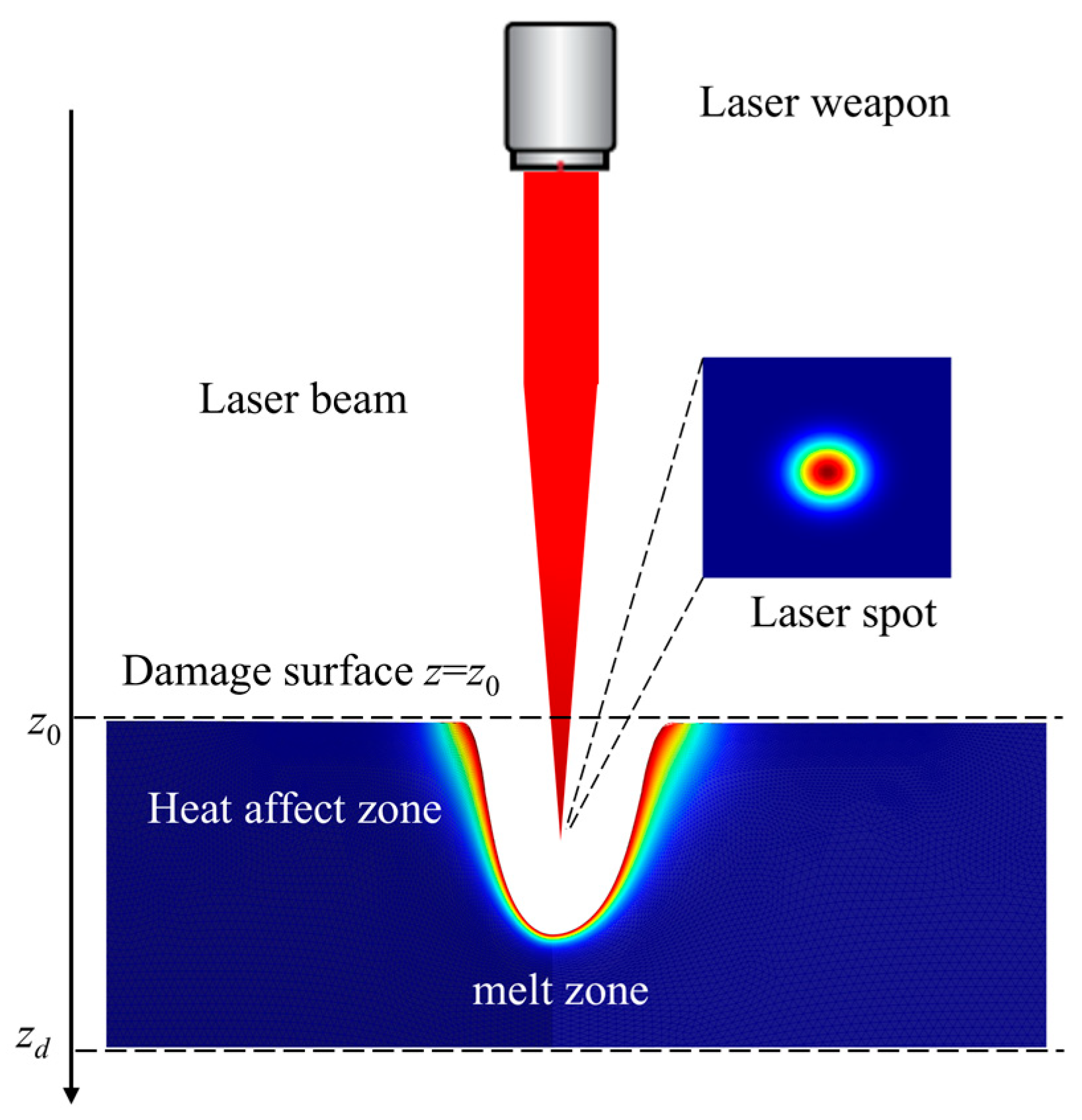
When a laser irradiates a target, there are phenomena of laser energy being emitted, absorbed, and transmitted by the target surface. Among them, the energy absorbed by the target causes the thermal damage effect [14]. Suppose the laser beam is incident perpendicularly on the target surface ( z = z 0 ), and the target is in the half-space where z z 0 as shown in Figure 4.
Suppose the reflectivity of the target surface to the laser is R, the absorption coefficient of the laser within the material is α, and the power density of the laser irradiated at z = 0 on the target surface through atmospheric transmission is I target . Then, the temperature field T of the target under laser irradiation is characterized by the heat conduction equation [38]:
ρ c T z , t t = ( k T ) + 1 R I target e α z , t > 0 , z > 0
where ρ is the density of the target material, c is the specific heat capacity, t is the irradiation time, k is the thermal conductivity of the material, and is the gradient operator. To analyze the essence of the laser thermal damage process, it is assumed here that the optical properties and thermal physical properties of the material do not change with the temperature and the state of the material. Meanwhile, the influence of the material liquefaction flow and convective heat transfer is ignored, and the central area of the light spot is treated as one-dimensional. When a uniform plate model of finite thickness is adopted, under the irradiation of a surface heat source and a continuous-wave laser, the analytical formula of its temperature field is as follows [39]:
T z , t = T 0 + 2 1 R I target π k k t π ρ c e ρ c 4 k t z 2 z 0 z 2 ρ c k t e x 2 d x
where T0 represents the initial temperature. When continuously irradiated, the phase transformation stage of the material begins when the temperature of the surface material reaches the melting point. After simplifying the above heat conduction, assuming that the density of the melted material is equal to that of the solid, that is, ρ m = ρ s = ρ , the solid-liquid surface condition can be expressed as follows:
T s = T q = T m k q T q z + k s T s z = ρ L m d z m d t ,   t > t m , z = z m ( t )
where the subscripts s and q represent solid and liquid states, respectively, m represents the molten state, and Lm is the latent heat of melting. The above equation is the differential equation of the interface position zm obtained by the coupling of heat flow in the solid–liquid zone. Obviously, the condition for melting penetration is that, when t = tm, the melting depth zm is equal to the thickness of the sheet zd. Currently, the state of the temperature field is as follows:
T z , t | z = z d t = t m = T z d , t m = T m 1 + L m / c s T m
Substitute the above equation into Equation (14) to obtain tm, which can then be used as the penetration time of the zd thickness material. However, it is difficult to precisely solve the laser melting problem. Therefore, an approximation assumption is adopted: when the thickness of the melting layer is much smaller than the thickness of the sheet, it can be regarded as steady-state melting; that is, the solid–liquid surface moves towards the solid zone at a constant speed. Once the molten liquid is formed, it is immediately removed, and the laser beam always irradiates the solid surface, that is, the zm interface. This represents a steady-state melting model [40]. Then, the time tm of melting penetration is expressed as follows:
t m = z d ρ c s T m T 0 + L m 1 R I target x , y
In the practical application of HELSs, the operator does not care about the detailed change process of the target material, but pays more attention to whether the target can be burned through and damaged. Therefore, when representing the laser damage capacity, the average time of penetration can be approximately calculated only. To visually describe the damage situation, it is assumed that the target being melted and penetrated is considered damaged. At this time, the damage threshold e th (kJ/cm2) is defined as the minimum energy density required to burn through a unit thickness of the target material; that is,
e th = min E m = z m ρ C s T m T 0 + L m
Suppose that, when the energy density of the laser surface irradiating the target exceeds the damage threshold, that is, when the condition e e th is met, the target will be damaged [41]. Then, for the continuous-wave HELS, the following formula exists:
e = 1 1.22 2 π η 0 τ P 0 D 2 t λ 2 L 2 β 0 2 + β T 2 + β B 2 + β J 2 e th = z m ρ C s T m T 0 + L m
Furthermore, the damage time of the HELS can be defined as follows:
t damage 1.22 2 π z m ρ c s T m T 0 + L m λ 2 L 2 β 0 2 + β T 2 + β B 2 + β J 2 η 0 τ P 0 D 2
Based on the above analysis, the damage time mainly depends on the characteristics of the laser transmitted through the atmosphere and the thermal damage effect. Specifically, under the given conditions of the laser’s wavelength, aperture, and other characteristics, the laser damage time will approximately linearly decrease as the laser power P0 increases, enabling the target to be damaged more quickly. It can be observed that the influence of the beam quality factor β on the damage time follows an approximately quadratic relationship. The factors involved, such as atmospheric turbulence, thermal blooming, and tracking and aiming errors, affect the damage time of HELSs to varying degrees. The damage time is approximately in a square relationship with the distance to the target. Meanwhile, the distance factor also affects parameters such as β to a certain extent, thereby influencing the damage time. In addition, the thickness and thermal parameters of the target material of the UAV also approximately linearly affect the damage time of the laser.
Based on the above discussion, taking the commonly used 2024 aluminum alloy material (5 mm) for UAVs as an example, the HELS damage capability under different turbulence intensities, different weather visibility, and different regional environments was modeled and simulated, and the relationship between the damage time and distance was obtained, as shown in Figure 5.
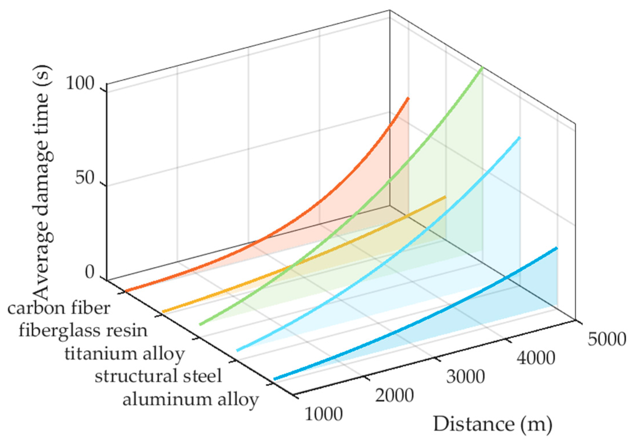
Furthermore, the damage times of various materials under the same irradiation conditions were compared. Given that the main structures of UAVs are generally made of metal materials such as aluminum alloy, titanium alloy, high-strength steel, and carbon fiber reinforced resin-based composite materials, the differences in their resistance to damage are significant. Among them, the damage mechanism of composite materials is particularly complex due to the diversity of the combination of the matrix and the reinforcement, and will not be discussed in detail. Here, the simulation results of Liu et al. [38] are cited, as shown in Figure 6.
It is easy to observe that the material significantly affects the destructive power of the laser. If the UAV adopts composite materials made of carbon fiber and coated with ceramic coatings, materials with high melting points (such as titanium alloy or high-strength steel), these materials can either scatter the laser radiation or remain undissolved rapidly at high temperatures, thereby significantly reducing the effect of the HELS damage effectiveness.
When using the HELS to defend the UAV swarm, the influence of the irradiation transfer time on assignment decisions also needs to be considered. The irradiation transfer time refers to the time required for an HELS to irradiate and destroy a target within range, and then adjust the direction of the laser beam to the next target according to the decision-making instruction. In the HELS with fast steering mirror (FSM) system, the irradiation transfer time can reach a millisecond response ( t FSM < 50 ms), but the maximum slew angle is usually limited to φ FSM = ±10°~±30° [42]. If the target exceeds this angle range, the physical rotation of multiple launchers on a traditional mechanical turntable is still required, which indirectly affects the decision-making time. When an HELS defends a multi-directional UAV swarm, the irradiation transfer time is as follows:
t trans = t FSM Δ φ i < 30 ° t FSM + Δ φ i φ FSM v slew Δ φ i 30 °
where Δ φ i represents the angle at which the i-th HELS needs to be transferred; v slew is the slew speed of the mechanical turntable; and the max slew rate of a typical HELS is 3 rad/s [43].
Finally, the total time required for an HELS to execute one damage decision is defined as one attack period, as follows:
t period , i = t trans , i + t damage , i

2.2. Malicious UAV Swarm Density Model

UAV swarms usually have the characteristics of having a large number, dense distribution, dynamic changes, and complex spatio-temporal distribution. Their malicious intrusion methods present a high degree of flexibility and uncertainty. The construction of the UAV target flow model can accurately depict the distribution trend of UAV swarms at different time and spatial positions, thereby providing a comprehensive and dynamic target information basis for the interception decision of HELSs. Since we mainly study the decision-making and assignment issues of HELSs, the path adjustment strategy of the swarm is not considered. According to the intrusion mode of the unmanned aerial vehicle swarm, it is divided into two cluster modes: multi-direction and multi-batch intrusion and large-scale simultaneous intrusion [44]. Suppose the time interval for each batch of UAV to reach the coverage area of the HELS is a random variable with an independent and uniform distribution f t , and the time intervals for the arrival of the UAV swarm in the two patterns are described, respectively, by the following distribution functions:
(1)
The malicious UAV swarm density model of multi-direction and multi-batch intrusion. UAV swarms may fly from multiple directions and disperse into multiple waves, and each wave invades at certain time intervals. This mode can disperse the defense forces and improve the efficiency of invasion. If each wave of unmanned aerial vehicles takes off in a random order, the time interval for the defense side to discover the target can be considered to follow a lognormal distribution:
f t = 1 2 π t σ exp ln t μ 2 2 σ 2
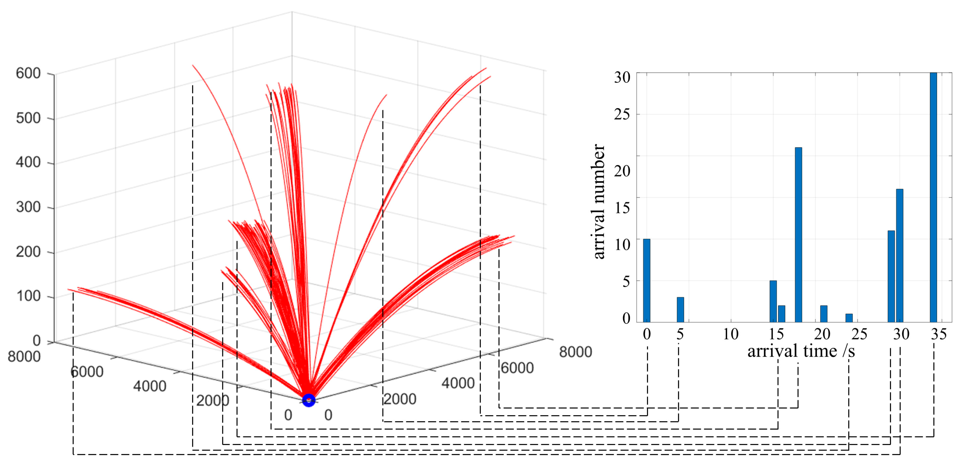
where μ and σ2 are, respectively, the expectation and variance of the lognormal distribution. If μ increases, the average arrival time interval will increase. If σ increases, the reached density will become more dispersed. The schematic diagram of the multi-direction and multi-batch intrusion model is shown in the Figure 7. The left side of Figure 7 shows the spatial situation of the UAV swarm in the fan-shaped space of the defending side, and the right side of Figure 7 shows the arrival time interval and quantity of each wave.
(2)
The malicious UAV swarm density model of large-scale simultaneous intrusion. By launching a large number of UAVs in a short period of time, the defense side is unable to effectively defend due to the saturated processing capacity, thereby increasing the probability of a UAV intrusion. The core lies in forming an absolute quantitative advantage in a short period of time. When the group of unmanned aerial vehicles takes off simultaneously, the time interval for the defense side to discover the target follows a uniform distribution:
f t = 1 b a , a < t < b 0 , otherwise
where a and b, respectively, represent the upper and lower limits of the UAV arrival time interval.

2.3. HELS–UAV–DRTA Model Formulation with Threat and Benefit Factors

In this section, the target threat of UAV and the defense benefit factors are established, respectively, thereby conducting a precise quantitative calculation of the damage effectiveness. Subsequently, based on the principle of optimal defense effectiveness, the HELS–UAV–DRTA model is constructed to achieve the dynamic and optimal assignment of HELS resources.

2.3.1. Quantification of Target Threat and Defense Benefit Factors

(1)
The threat factor of the target height. The height from the ground of UAVs has a direct impact on the probability of invasion. UAVs flying at low altitudes are more likely to penetrate, and their threat factor is higher than that of targets flying at high altitudes. Meanwhile, the atmospheric environment in which low-altitude-flying UAVs are located is more complex, which directly affects the damage time of HELSs. Therefore, their threat factor is also higher. Therefore, the model of the height threat factor established based on the exponential decay function is as follows:
T r h , j = 1 exp k h 1 h j / h max 1 exp k h
where T r h , j is the normalized threat factor of UAVs based on height; h j represents the height of the j-th target; h max is the maximum height of the first point of all targets discovered by the detection system; and k h > 0 is the parameter that controls the steepness of the exponential decay function curve. The larger k h is, the more intensely the low-altitude threat increases, which meets the sensitive requirements for the low-altitude threat assessment. The physical meaning is as follows: the lower the height of the target is, the more intense the increase in its threat factor is and the easier it is to invade.
(2)
The threat factor of the target velocity. The maneuverability of the UAV increases with the increase in velocity. However, due to the limitations of the power performance, excessive speed means that the payload capacity of the UAVs is insufficient. Therefore, the speed threat factor is established based on the exponential function as follows:
T r v , j = exp v j v 0 v 0
where T r v , j is the normalized threat factor of UAVs based on the velocity; v j represents the actual flight velocity of each UAV; and v 0 is the preset speed. The physical meaning is as follows: the closer the velocity of the UAV is to v 0 , the more threatening it is. Both too high and too low a velocity will reduce its threat level.
(3)
The threat factor of the safe distance from the protected assets. The safe distance refers to the remaining distance for the UAV to invade the protected target along the shortest path starting from the current state. The shorter the remaining flight distance of the UAV is, the shorter the time window for defense will be, and the greater the urgency will be. Therefore, a distance threat factor model is established based on a linear function:
T r L , j = L max L j L max L safe
where T r L , j represents the distance-based normalized threat factor of UAVs; L j is the distance between each UAV and the protected assets; and L max and L safe represent the farthest distance at which the target is first discovered and the radius of the secure airspace for protected assets. The physical meaning is as follows: the closer the remaining distance between the UAV and the protected assets is, the greater the threat is.
(4)
The benefit factor of HELS resource consumption. The energy storage of HELS is limited [43]. When dealing with UAV swarms, priority should be given to targets with shorter damage times to defend more targets with limited resources. Furthermore, UAVs with similar spatial angles should be selected in order to reduce the irradiation transmission time and improve the damage efficiency. Therefore, the benefit factor model based on HELS resource consumption is established based on the sigmoid function:
B r c , i j = 2 1 + exp k c t period , i j
where B r c , i j represents the resource consumption benefit factor of HELS i selecting target j; and k c > 0 is a parameter in the sigmoid function that controls the steepness of the yield curve. The larger k c is, the more sharply the interception benefit decreases with t period . Its physical meaning is as follows: When defending UAV swarms, an extremely high priority is given to the targets that can be destroyed in a short time, while the selectivity of the targets that need to be irradiated for a long time will rapidly decrease.
(5)
The benefit factor of the HELS application value. Due to the different performances of HELSs, their application values also vary. Although high-performance HELSs can quickly destroy targets, their usage cost is relatively high. In addition, HELS with more remaining power should be given priority for use to avoid the depletion of resources due to the concentrated use of a certain HELS, which makes it impossible to carry out subsequent tasks. Therefore, establish the cost–benefit model of HELSs based on linear functions:
B r s , i j = α c 1 1 P i i P i + α c 2 t battery , i t damage , i j t battery , i
where B r s , i j is the application value benefit factor when the i-th HELS irradiates the j-th target, and α c 1 , α c 2 0 , 1 2 is the linear weighted control parameter, α c 1 + α c 2 = 1 ; and Pi is the initial power of the i-th HELS and t battery , i is the remaining battery magazine of the i-th HELS. The physical meaning is as follows: prioritize the use of HELSs with a lower power and larger remaining battery magazine to carry out tasks to save application value.

2.3.2. Mathematical Formulation

Typically, dynamic target assignment models are divided into the Shoot–Look–Shoot model and the Two-Stage model. Both types of models make multi-round decisions based on the static target assignment model [45]. The difference is that the Shoot–Look–Shoot model is a multi-round decision-making problem, and the number of remaining HELSs and targets in each round is known. The Two-Stage model is a multi-stage decision-making problem, and the number of incoming targets in each stage is determined by the state of the previous stage. Considering the continuous irradiation state of HELSs damaged the targets and the uncertainty of the attack scale of UAV swarms, based on the multi-stage description method of the Two-Stage model and integrating the target threat factor and the interception benefit factor, the HELS–UAV–DRTA model based on the optimal energy criterion is established as follows:
max t k = 1 T i = 1 m j A t k x i , j ( t k ) λ 1 λ 11 T r h , j t k + λ 12 T r v , j t k + λ 13 T r L , j t k + λ 2 λ 21 B r c , i j t k + λ 22 B r s , j t k
s . t . A t k + 1 = A t k B t k K t k ( a ) t battery , i ( t k + 1 ) = t battery , i ( t k ) j = 1 n x i j ( t k ) t damage , i j ( t k ) , i = 1 , 2 , , m ( b ) x i j ( t k ) t battery , i ( t k ) W i ( t k ) , i = 1 , 2 , , m ( c ) t k + 1 = t k + min x i j ( t k ) t period , i j ( t k ) 0 , t , t battery , i ( t k ) > 0 L j ( t k + 1 ) > L safe ( d ) i = 1 x i j t k 1 , i = 1 , 2 , , m ( e ) j A t k x i j t k = 0 , t k t fire , i , t fire , i + t period , i j , i = 1 , 2 , , m ( f ) t fire , i = t k , x i j t k = 1 , j = 1 , 2 , , A t k ( g ) x i j = 0 , 1 , i = 1 , 2 , , m , j = 1 , 2 , , n ( h )
where λ 1 , λ 2 0 , 1 2 are the weights of the threat and benefit factors, respectively, and λ 1 + λ 2 = 1 . λ 11 , λ 12 , λ 13 , λ 21 and λ 22 are the weights of each factor, respectively. t k is the number of stages, m represents the total number of HELS, and n is the total number of UAV. A t k , B t k and K t k are the target set in the t k stage, the newly discovered target set, and the target set being irradiated, respectively. t battery , i is the remaining battery magazine of the i-th HELS, and x i , j ( t k ) is the decision variable for the i-th HELS to irradiate on the j-th target. t fire , i is the moment when the i-th HELS begins irradiation.
Equation (30) is the objective function, indicating that the result of the target assignment is to maximize the target threat and defense benefit factors. This objective function provides a flexible way to adjust the damage strategy to better adapt to specific requirements. For example, when defending important assets, the weight λ1 of the target threat factors can be increased. The assignment plan will tend to choose the strategy that can damage the target as soon as possible, regardless of the consumption of laser energy. Similarly, for regular defense tasks, the weight λ2 of the interception benefit factors will be relatively high, and the system will tend to choose interception schemes that can significantly reduce resource consumption.
Equation (31) is the constraint condition, and its physical meaning is as follows:
Constraint (a). The distributable targets for each stage consist of the targets existing in the previous stage and newly discovered targets. Targets that are currently being irradiated do not participate in the allocation.
Constraint (b). The remaining battery magazine of all HELSs is the rated battery magazine minus the resources consumed by the executed tasks.
Constraint (c). For each HELS, when performing the damage task on the j-th target in the t k stage, the required damage time must be less than the remaining battery magazine of the current HELS.
Constraint (d). When any HELS has a remaining battery magazine and the distances from all targets to the protected asset are greater than the safe distance L safe , the next decision time step t k + 1 is the current time step t k plus the minimum value of the irradiation periods t period , i j of all HELSs and the fixed time step t , that is, min x i j ( t k ) t p e r i o d , i j ( t k ) 0 , t ; if none of the laser systems perform the irradiation mission, the time step increases by t .
Constraint (e). There is no more than one HELS irradiating a single target at the same time.
Constraint (f). When the HELS irradiates the target, no target is assigned within the current irradiation period.
Constraint (g). When the i-th HELS performs an irradiation mission to the j-th target, the start and end time periods of this mission are from the moment the irradiation mission is carried out to the moment when one period of damage is completed.
Constraint (h). The decision variable x i j for each HELS takes the value 0 (standby) or 1 (the i-th HELS irradiates to the j-th target).
The computational complexity of this two-stage assignment model is analyzed as follows: The worst-case complexity is O m n T , where m is the number of HELSs, n is the maximum number of UAV targets per stage, and T is the total decision stages. This occurs when all HELSs evaluate all targets at every stage. The average-case complexity is O m k T , where k n is the average number of targets within the effective damage range of an HELS.
Finally, the model applicability boundaries are discussed:
(1)
Environmental boundary. The model is built upon the Hufnagel–Valley turbulence model and the LOWTRAN-7 atmospheric-attenuation model. It is applicable to atmospheric conditions with medium turbulence or lower ( C n 2 < 2.5 × 10⁻¹³ m−2/3), and is superior to the visibility of light haze ( κ ≥ 5 km). Extreme weather conditions such as heavy rain and fog will cause the damage conditions to fail.
(2)
Target boundary. The model is designed for small commercial UAVs and assumes that the material is easily damaged; it is not applicable to high-maneuverability military UAVs or supersonic targets. Given that the damage effective range of HELSs is at the kilometer level, the target distance is typically set to L ≤ 10 km. If the target is replaced with a carbon-fiber–ceramic-coated composite structure, titanium alloy, or a surface-coated polyimide with high laser resistance, a higher-power HELS system should be used for calculation.
(3)
System boundary. The results are valid only within the “material–power” feasible region; that is, the HELS battery magazine must be able to support the cumulative irradiation time for all selected targets; if the required damage time far exceeds the system’s capability, at this time, the system should eliminate this target or adjust the laser power/illumination strategy during the initial stage.

3. MADDPG-IA Algorithm Design and Implementation

When solving the HELS–UAV–DRTA problem with DRL, it can be regarded as a multi-step RL process in the continuous state space and the discrete action space. The task of learning is to find an optimal target assignment strategy to maximize the global benefit. Considering that using a single agent to determine the assignment problem would lead to an overly large state space that is difficult to traverse and unable to provide satisfactory results within a reasonable time, a multi-agent full cooperative relationship will be adopted for decision-making. Each agent optimizes its own behavior, avoids mutual interference, and collaborates to complete the damage decision to obtain the highest global benefit. In related studies, the MADDPG algorithm is a multi-agent RL algorithm that adopts the centralized training with decentralized execution (CTDE) paradigm [46,47,48]. It can handle multi-agent cooperation problems that traditional reinforcement methods cannot solve and is suitable for dealing with scenarios with complex environments. Treating each HELS as an agent, through centralized training, all HELS agents can access global information, which is conducive to learning effective coordination strategies. When implementing decisions, each HELS agent makes decisions only based on local information, thereby reducing the computational burden and improving the real-time decision-making ability. Therefore, the MADDPG algorithm is an effective method for solving the collaborative exploration of multiple HELS agents. An improved MADDPG algorithm based on the state coding of the attention mechanism and the sparse reward exploration strategy driven by an RND-based intrinsic reward module is proposed to solve the HELS–UAV–DRTA model to achieve the optimal decision-making. Here, the attention mechanism acts like a spotlight that lets each HELS focus on the most relevant UAVs regardless of how many targets appear, while the intrinsic reward module supplies an extra reward for visiting new states, alleviating the sparse-reward problem.

3.1. MADDPG Framework in HELS–UAV–DRTA

The MADDPG algorithm is an extension of DDPG in the multi-agent domain and is an algorithm based on the Actor–Critic framework [47]. Each agent consists of two neural networks, the Actor network and the Critic network. Its current network parameters are represented by θ π and θ Q , and the corresponding target network parameters are represented by θ π and θ Q . In the centralized training stage, the Actor network of each agent interacts with the environment, utilizes the information of other agents and the global situation, and selects the corresponding action based on the current observation value s and policy π. The Critic network accepts this action, calculates the target Q value, and evaluates and provides feedback on this action. The Actor continuously optimizes the policy based on the feedback from the Critic network.
Suppose the observation set of n agents is s = s 1 , , s n , the random policy set of agents is π = π 1 , , π n , the parameters of the Actor network are θ π = θ 1 π , , θ n π , and the action set is a = a 1 , , a n . Then, the cumulative expected reward J θ i and policy gradient θ i π J π i of the i-th agent are as follows:
J θ i = E s ~ p π , a i ~ π i t = 0 γ t r i t
θ i π J π i = E s , a ~ D θ i π π i a i | s i a i Q i π s , a 1 , , a n | a i = π i s i
where γ t is the discount factor, representing the influence of the current action on the expected reward of the subsequent actions; r i t represents the expected reward; p π refers to the probability distribution of the global state s when the strategy π is executed; and Q i s , a 1 , , a n is the centralized action value function. For deterministic strategies πi, the above gradient formula will be as follows:
θ i π J π i = E s , a ~ D θ i π log π i a i | s i Q i π s , a 1 , , a n
where D is the experience replay memory for storing data, which records the experience samples s , s , a 1 , , a n , r 1 , , r n stored by all agents, namely, the observation state at the current moment, the observation state at the next moment, actions, and rewards. The Critic network uses global information and achieves the value assessment by minimizing the loss function L θ i Q , as follows:
y = r i + γ Q i s , a 1 , a n | a j = π j s j
L θ i Q = E s , a , r , s Q i s , a 1 , , a n y 2
In Equation (35), agent i calculates the y value through environmental information and the actions of other agents to functionally approximate the strategies of other agents, enabling the critic module to utilize global information to guide the actor module. In the Critic network, the target network will obtain the Q value output based on the input behavior and state, and calculate the gradient loss based on the true value generated by the valuation network for training the network. The target network will also update the Actor network at certain time steps. Each agent updates the parameters of the target network through a soft update. The update rule is as follows:
θ i π ϖ θ i π 1 ϖ θ i π θ i Q ϖ θ i Q 1 ϖ θ i Q
where ϖ is the soft update coefficient. Throughout the entire process, each agent samples independently and learns uniformly, and each agent can have an independent reward mechanism.
Next, the HELS–UAV–DRTA model is subject to environmental transformation to adapt to the computational framework of the MADDPG algorithm. The HELS–UAV–DRTA model is a type of partially observable Markov game. Each HELS is regarded as an agent, and the agents are in a fully cooperative state to jointly achieve the optimal interception scheme. Each HELS agent needs to determine when and at what distance to damage the target to achieve the optimal energy distribution and maximum number of damages for the UAV swarm. Therefore, the dynamic decision-making process of the HELS–UAV–DRTA is modeled as an MDP model of n agents, which includes the state space s, the agent action space a, and the reward function r.
(1)
State space design
In the HELS–UAV–DRTA scenario, the state space is mainly composed of the state s i LaSW of the agent itself and the target state s i UAV observed by the agent. At any moment, the state of the i-th agent itself includes the deployment position p pos , i of the agent, the remaining electricity t battery , i , the remaining time t duration , i of continuous irradiation, and the direction φ i of the current laser rotation axis, which is defined as follows:
s i LaSW = p pos , i , t battery , i , t duration , i , φ i R 4
while the target state observed by the i-th agent includes the number m of UAVs observed by the current agent, the distance Lj between the j-th UAV and the agent i, the flight height hj, the velocity vj, and the atmospheric environment parameter Aj of the flight area, which are defined as follows:
s i UAV = m i , L j , h j , v j , A j j m i R 4 m i + 1
Then, the observation state of each agent is
s i = concat s i LaSW , s i UAV R 4 m i + 5
where concat(·) is the concatenation function. In the HELS–UAV–DRTA environment, before each agent makes a damage decision, it will observe its state space and select an appropriate action for decision-making.
(2)
Discrete action space
The One-Hot encoding strategy was adopted to design the actions performed by each HELS agent and assign decision variables to the target for whether to cause radiation to a certain target at this stage. In addition, we design an action in a delayed waiting state; that is, at this time, the HELS should wait for the target to continue approaching without performing the irradiation damage task. If there are m UAV targets, then there are m + 1 specific actions, which means that the action space is m + 1 dimensions. The design of the action space is as follows:
a 1 a 2 a n = 1 0 0 0 0 1 0 0 0 0 1 0 0 0 0 1 n × m + 1
An explanation of the action space: decode a 2 = 0 1 0 0 as arg max a 2 = 2 , which indicates that HELS agent 2 performs the irradiation task on the 2-th target; decode a i = 0 0 0 1 as arg max a i = m + 1 , which indicates that HELS agent i continues to wait and does not perform the irradiation task; and argmax(·) is the function that returns the index of the maximum value in a vector.
In terms of the design of action functions, the MADDPG algorithm needs to make the actions of the agent differentiable with respect to its policy parameters. Therefore, for the discrete action space, the Gumbel–Softmax method is adopted to obtain the approximate sampling of the discrete action distribution, thereby allowing the model parameters to be updated using gradients during backpropagation [49].
(3)
Reward function
In MADDPG, the quantified reward function is a key indicator for measuring action performance and training models. It directly determines the agent’s preferences for different behaviors during the decision-making process, and thereby affects the convergence and final performance of the entire learning process. In the HELS–UAV–DRTA model, a reward function based on the threat factor and interception benefits factor was constructed, aiming to guide HELS agents to make the optimal choice in a complex decision-making environment through quantitative means:
r i e = λ 1 λ 11 T r h , j t + λ 12 T r v , j t + λ 13 T r L , j t + λ 2 λ 21 B r c , i j t + λ 22 B r s , j t arg max a i t m + 1   a n d   t remain , i = 0 1 arg max a i t m + 1   a n d   t remain , i > 0 0.1 exp β d t arg max a i t = m + 1
where tremain,i represents the remaining time of continuous irradiation, tremain,i > 0 indicates that the HELS agent i is still continuously irradiating the previous target, and tremain,i = 0 indicates that the agent is waiting for a decision and has the irradiation conditions. βd represents the attenuation rate. The physical meaning is as follows: when the One-Hot decoding value of the action ai performed by agent i is not m + 1 and the irradiation conditions are met, HELS agent i performs irradiation on the target j and obtains the reward value based on the threat factor and the interception benefit factor; if the irradiation decision is executed but the agent does not have the irradiation conditions, then this decision is a wrong one and a negative reward is received; if HELS agent i chooses to wait and does not perform the irradiation task, a positive reward that decays over time will be given to encourage the HELS agent to choose more delayed damage strategies in the early stage of decision-making.

3.2. Enhanced MADDPG with Attention and Intrinsic Reward Mechanisms

In the HELS–UAV–DRTA environment, the MADDPG algorithm, with its architecture of centralized training and distributed execution, can effectively achieve the optimal interception decision. However, in specific applications, this algorithm still has problems such as the uncertain dimension of the state space and the short-sightedness of the agent: (1) The dimension of the input vector of the HELS-agent may be different at each moment, because the number of UAV targets decreases with the damage of other HELS agents and changes constantly with the influx of target flows. However, the traditional neural network structure is unable to handle such variable-length inputs. The number of randomly occurring and damaged or vanished UAVs leads to the agent’s inability to fit the dimensions. (2) The agents are short-sighted. During the decision-making process of each HELS agent, they overly focus on the local rewards of the current state and lack an in-depth exploration of the global rewards. This leads the agent to tend to choose targets that appear early and are far away, depleting the battery magazine and failing to achieve the optimal damage effect. Furthermore, since HELS require continuous irradiation, effective rewards cannot be obtained during this period, making it difficult for HELS agents to explore the global states they have not experienced. In response to the above problems, the MADDPG-IA algorithm is adaptively improved to meet the solution requirements.

3.2.1. Attention-Based State Encoding

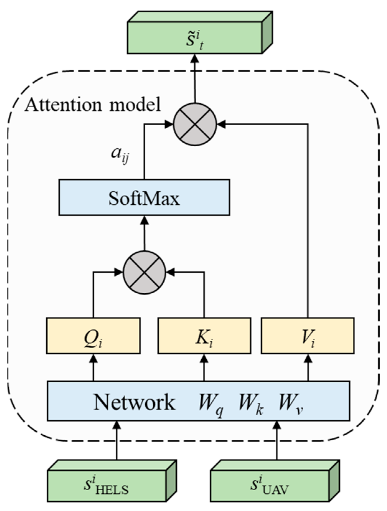
In the existing research, there are commonly two approaches to solve the problem of the mismatch between the dimension of the input vector and the dimension of the neural network. (1) Suppose the agent has a God’s-eye view and can directly obtain the global status of the UAV. This approach can solve the problem well, but it is not in line with reality. (2) Suppose each agent can obtain a maximum of m surrounding UAVs. When the number of UAVs is less than m, the “death masking” method is adopted to set all the status of other UAVs to “0”. When the number of UAVs is greater than m, only the status of the nearest m drones is selected for acquisition. This approach may cause the unmanned aerial vehicle to lose some status information, reducing the optimization effect of the algorithm [50]. The attention mechanism can convert input vectors of different dimensions into output vectors of fixed dimensions, and supports parallel settlement, with a high computational efficiency [51]. A state coding network based on the attention mechanism is designed to solve the problem of dynamic changes in the input dimension. Intuitively, attention acts like a soft selector: it weighs every visible UAV and returns a fixed-length summary that always fits the neural network. The implementation process is shown in Figure 8.
In Figure 8, the state s i LaWS of the agent itself is used as the Query, and the state s i UAV of each UAV target in the target observation set is used as the Key and Value, respectively, input into the corresponding networks W q , W k , and W v used to calculate the Query, Key, and Value matrices in the attention mechanism, as follows:
Q i = W q s i LaWS R d k K j = W k s i UAV R d k V j = W v s i UAV R d v
After the network transformation, Q i represents the current ability and intention of the agent, K j represents the attentiveness of the target, and V j carries complete information of the target. The attention weight a i j is obtained by calculating the similarity between Q i and each K j , as follows:
a i j = softmax Q i K j T d k
where, dk is the dimension of the key vector. After the Softmax function, the weights a i j corresponding to different feature information are obtained, and the agent i dynamically decides which targets ( K j ) to focus on according to its own state ( Q i ). For example, the target a i j that is closer to the UAV target increases significantly. Finally, V j is weighted and summed according to the weights to obtain the attention value, to integrate the UAV information with variable dimensions into the feature vector output with fixed dimensions, that is, the state space is expressed as:
s ˜ i = softmax W q s i LaWS W k s i UAV T / d k W v s i UAV = Attn W q s i LaWS , W k s i UAV , W v s i UAV R d attn
where dattn is the attention network hyperparameter, and Attn(·) is the attention mechanism function. The improvement of the state dimension based on the attention mechanism can convert the dynamic UAV state information randomly appearing in the airspace and real-time interception into feature information with fixed dimensions, which is convenient for the input of the subsequent neural network. At the same time, it also has different focuses on the state information of the UAV with a higher threat factor and interception factor, which improves the efficiency of processing.

3.2.2. Intrinsic Reward-Driven Exploration

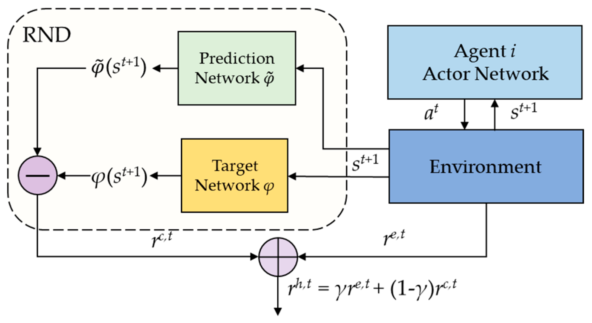
In the HELS–UAV–DRTA environment, due to the characteristics of the continuous irradiation of HELS, the reward values are often sparse and the positive rewards are too few, so it is difficult for the agent to obtain an effective exploration strategy. By adding an intrinsic reward module to the MADDPG algorithm, encouraging agents to observe and explore new environments is a proven method [48]. We adopt an RND-based intrinsic reward module as the intrinsic reward source and extends it to the multi-agent scenario [52,53]. RND is a self-supervised predictor trained to match the frozen output of a randomly initialized target network, yielding epistemic-uncertainty-shaped intrinsic rewards. In plain words, this module provides agents with a reward signal proportional to the novelty of the encountered states, encouraging the exploration of unfamiliar situations rather than repeating known actions. The module design is shown in Figure 9.
Specifically, the RND-based intrinsic reward module contains two neural networks. (1) Target network φ : randomly initialized and fixed to generate a feature representation of the state. (2) Prediction Network φ ˜ : trained on data collected by the agent, the goal is to minimize the prediction error from the target network, which is the intrinsic reward r i c . RND uses this prediction error to encourage the agent to explore unseen or less visited states. The agent’s target network and prediction network have the same architecture, and both use convolutional neural networks and fully connected layers to perform feature transformations, whose feature expressions are φ s ˜ i t + 1 and φ ˜ s ˜ i t + 1 , respectively. The prediction error between the feature encoding of the target network and the prediction network at time t+1 is used as the intrinsic curiosity reward r t c at time t, as follows.
r i c , t = β r φ ~ s ~ i t + 1 φ s ~ i t + 1
where β r is the adaptive coefficient. β r = β r 0 e k r t adopts the curriculum-learning strategy, which decays with the number of training steps. kr is the control parameter and is set to 1 × 10⁴. To perform the multi-agent cooperative interception mission in a continuous environment with a discrete action space, the reward r i e obtained by interacting with the environment reward and the intrinsic reward r i c are mixed to obtain the hybrid reward r i h as follows:
r i h , t = γ r i e , t + 1 γ r i c , t
where the dynamic weight γ is automatically adjusted based on the sparsity of the environmental reward. The improved reward function calculation method effectively optimizes the exploration process of the agent, encourages the agent to make risky decisions to delay decision-making to await optimal timing; even if the UAV swarm enters the attack range, it will not immediately execute the action. Instead, when the distance is closer, it can damage faster, save energy, and obtain greater global benefits.

3.2.3. MADDPG-IA Algorithm Workflow

Based on the RND-based intrinsic reward module and state coding network based on the attention mechanism, the MADDPG-IA algorithm is improved to solve the HELS–UAV–DRTA problem in a discrete action space. The algorithm also uses the experience replay mechanism, dual network architecture, and centralized training decentralized execution idea [46]. Considering the cooperative interception problem of multi-HELS, the mission objectives of the agents are the same, and the training objectives of the policy network are the same, so all agents share the network and experience pool for decision-making and training [54]. Based on the above analysis, the architecture of the MADDPG-IA algorithm is shown in Figure 10, and the algorithm pseudocode is shown in Algorithm 1.
Algorithm 1. Pseudocode of the MADDPG-IA Algorithm for the HELS–UAV–DRTA Environment
1. Initialize. Initialize the parameters of Actor network and Critic network θ π , θ π , θ Q , θ Q , experience replay pool D, discount factor γ, soft update parameter ϖ , adaptive coefficient β r , β d the RND-based intrinsic reward module’s target network parameters φ and predict network parameters φ ˜ .
2. For episode = 1 to MaxEpisode Do
3.   Reset. HELS–UAV–DRTA environment; obtain the initial state s i 0 i = 1 n .
4.   While not Done
5.    The observed state of each agent is attention-encoded to obtain the state s ˜ i t at time t.
6.    Based on the current Actor network, the action a i t ~ π i s ˜ i t is selected.
7.    The joint action is executed and the observed reward r i e , t and the next state s i t + 1 are obtained.
8.    Calculate the intrinsic reward r i c , t using Equation (46) and calculate the hybrid reward r i h , t using Equation (47).
9.    Store the experience into the playback experience pool D.
10.  For agent i to N Do
11.   Sample a batch of data from D.
12.   Update the Critic network θ Q by minimizing the loss function according to Equation (36).
13.   Update the Actor network θ π through gradient descent according to Equation (33)
14.   Soft-update target network θ π and θ Q parameters according to Equation (37).
15.   Minimize the prediction error of the intrinsic reward network. Update the prediction network through gradient descent.
16.  End For
17.  if tbattery,i = = 0 or nUAV = = 0 or min(L) < Lsafe
18.   End While
19. End For

4. Simulation and Analysis

4.1. Experimental Environment and Parameter Settings

The experimental platform is developed using PyCharm 2024.3.1.1, leveraging Anaconda3 (2024.10) as the Python environment, on Windows 11. The experimental program was written using Python 3.12.9, and the neural network was built using torch 2.6.0 + cu126. The computer is equipped with AMD Ryzen 7 5800H with Radeon Graphics@3.20 GHz, 32 GB of RAM, and NVIDIA GeForce RTX 3060 Laptop.
The experiment is divided into two parts. The first part is the typical scenario analysis. By setting up typical HELS–UAV–DRTA environments, the decision-making plan is calculated and the rationality of the scenarios is analyzed. The second part is the performance comparison and evaluation. By designing ablation experiments and algorithm comparison experiments, the performance of the MADDPG-IA algorithm is evaluated.
Based on the potential of HELSs and malicious UAV swarms, simulation experiments of small-scale and large-scale scenarios are set up. The initial parameter settings of the experimental environment are shown in Table 1. Among them, HELSs can be classified into low-performance and high-performance types. Two HELSs (one low-performance and one high-performance) are deployed in small-scale scenarios, and five HELSs (three low-performance and two high-performance) are deployed in large-scale scenarios. The deployment method is centralized deployment near the protected assets. The UAV swarms adopt a density model of multi-direction and multi-batch intrusion, distinguishing between a small-scale pattern (10 UAVs, two-wave) and large-scale pattern (50 UAVs, five-wave). The atmospheric environment is set with sunshine or a light haze, and weak or medium atmospheric turbulence intensity in rural, desert, or coastal areas. The parameters of the MADDPG-IA algorithm and other parameter settings of HELS–UAV–DRTA are shown in Table 1 [55].
Each scenario was evaluated over 100 independent simulation runs with randomized initial conditions (UAV positions, velocities, and environmental noise). Damage rates were computed as the average proportion of UAVs successfully damaged before breaching the protected zone across all runs. The random seed for each run was varied to ensure statistical independence.

4.2. Typical Scenario Experiments of HELS–UAV–DRTA

4.2.1. Experimental Simulation Analysis of Typical Scenarios

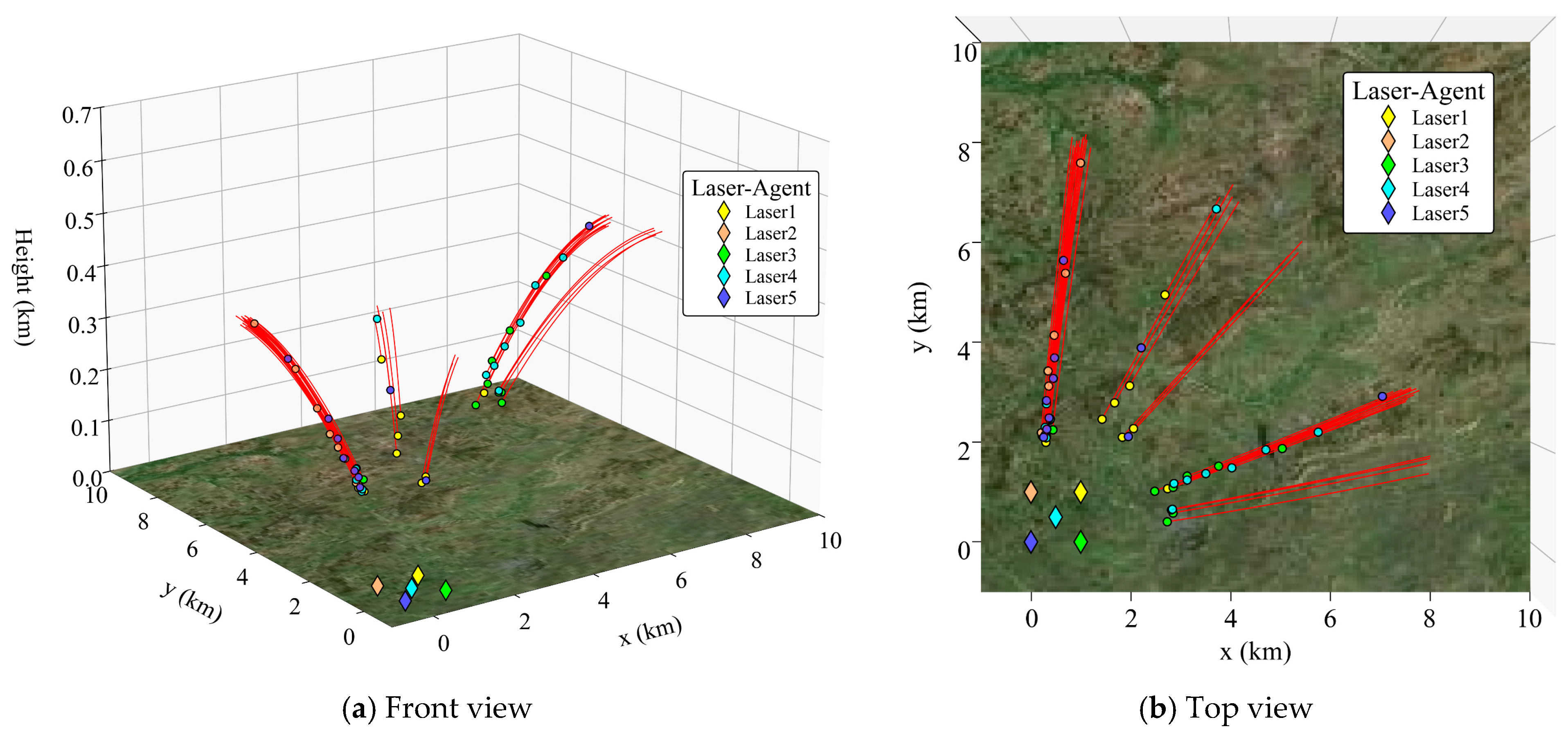
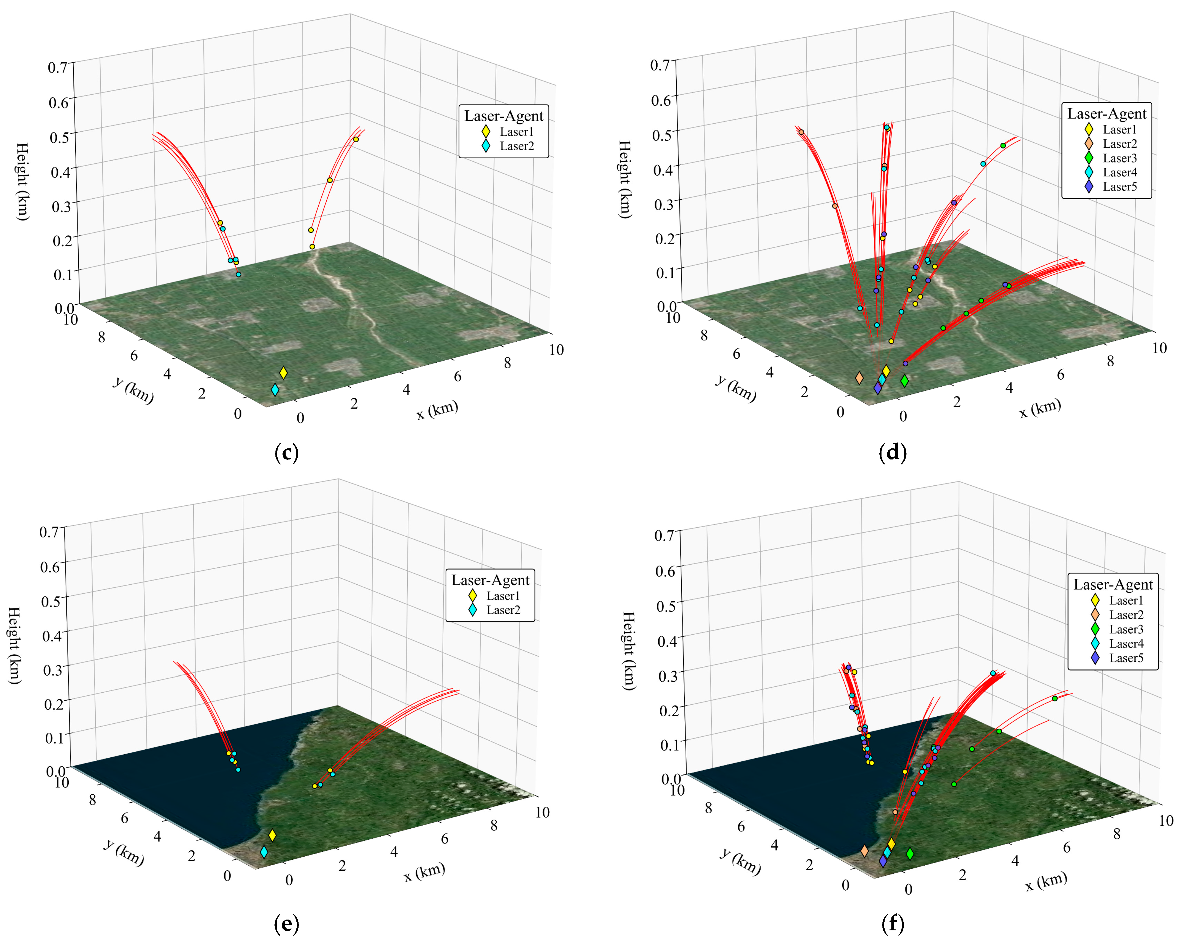
To visually demonstrate the intelligent decision-making ability based on the MADDPG-IA algorithm in solving the HELS–UAV–DRTA problem, this section will construct a large-scale UAV swarm invasion scenario in a rural, sunshine, and weak turbulence atmospheric environment. Through the decision-making of five HELS agents, the damage of 50 UAVs will be achieved. Figure 11 shows the target allocation result of intelligent decision-making, and Figure 12 shows the irradiation timing of each HELS agent.
In Figure 11, the rhombus pattern represents the distribution positions of the HELS agent. The red curves represent the flight trajectories of UAVs in various directions and heights. The invasion target of the UAV swarm is the protected asset at the origin (also the position of HELS agent 5). The circles of different colors on the curve are marked as the damage decision positions of the corresponding HELS agent for the UAVs. During this simulation process, the UAVs came from five directions and covered the airspace of a 90° sector. Low-performance HELS agents 1, 2, and 3 are responsible for their respective directions, while high-performance HELS agents 4 and 5 provide supplementary defense. Each HELS agent conducts intelligent damage based on the observation status of UAVs entering its coverage range.
In the early stages of decision-making in Figure 12, due to the large number of UAVs in the air, the strategy of delaying decision-making to await the optimal timing is risky. HELS agents 2, 4, and 5 were the first to start irradiating targets at distances (height) of 7.32 km (0.3 km), 7.27 km (0.3 km), and 7.25 km (0.5 km) from the protected asset. This is because HELS agent 2 was deployed at an earlier position and had a high damage efficiency. HELS agents 4 and 5, due to their high performance and rapid damage, have also begun to be irradiated to obtain higher global benefits. HELS agent 4 was deployed earlier than HELS-agent 5, so a target with a lower altitude (0.3 km) and a greater threat was chosen. HELS agents 1 and 3 have fewer targets in their respective directions. Based on their observation states, they have evolved the strategy of delaying decision-making to await optimal timing to reduce the irradiation time. Therefore, decisions have not yet been made.
In the middle and later stages of decision-making, after damaging scattered UAVs in all directions, each HELS agent concentrated on irradiating UAV targets in the 0° to 15° direction. Eventually, the damage of 50 UAV targets was completed. At this time, the last target was 1.68 km away from the protected asset, and the HELS agent had battery magazines remaining at 64.39 s, 0 s, 36.78 s, 7.88 s, and 9.55 s. Meanwhile, in the later stage of decision-making, the influence of the irradiation-transfer time becomes increasingly pronounced. The HELS agent will prioritize targets within the same wave to reduce the irradiation transfer time and avoid delaying the next irradiation.

4.2.2. Model Generalization Experiment

Set up a small-scale scenario (2 HELSs–10 UAVs) and a large-scale scenario (5 HELSs–50 UAVs) to verify the universality of the MADDPG-IA algorithm in dealing with the HELS–UAV–DRTA problem at various scales. Considering that HELSs have the characteristic of having a strong weather dependence, three typical atmospheric environments are simulated under the background of sunshine and a weak turbulence desert environment, light haze and a medium turbulence rural environment, and sunshine and a weak turbulence coastal (rural–marine) environment in mid-latitudes [37]. To visually represent the influence of atmospheric environment changes on decision-making results, in the analysis of the coastal environment, the coastal boundary is taken as the dividing line of atmospheric parameter changes to calculate the atmospheric influences of the marine environment and the rural environment, respectively, and the atmospheric transition change process at the terrain junction is not considered for the time being. The experiment was independently conducted 100 times. One of the simulation results is shown in Figure 13. The full statistical analysis of the damage rate in large-scale scenarios can be found in Table 2.
The following conclusions can be analyzed and drawn:
(1)
The scale of the UAV swarm affects the damage decision. Under the same atmospheric environment, the decision-making timing of each HELS agent changes with the variation in the scale of the UAV swarm. Take Figure 13a,b as examples. In the small-scale scenario shown in Figure 13a, due to the smaller number of targets in the airspace, the HELS agent has more reaction time. Therefore, on the premise of ensuring safety, the HELS agent will delay the damage decision, choose to irradiate the target at a closer distance, and exchange a shorter irradiation time for damage for a higher damage benefit. In Figure 13b, as the number of targets increases, the agent cannot bear the risk of the strategy of delaying decision-making to wait for the optimal timing. Therefore, it will make decisions as early as possible to damage as many targets as possible. In the above-mentioned desert environment, the distance for the first irradiation of the target in the small-scale scene was 3.79 km, and that in the large-scale scene was 7.18 km.
(2)
The atmospheric environment affects the damage decision. When the atmospheric environment is favorable, the damage ability of HELSs is strong, and the HELS agent has more flexible decision-making strategies and can obtain more decision-making opportunities by intercepting at a closer distance. In the small-scale scenarios (Figure 13a,c,e), the distances of the first target interception were 3.79 km (desert), 6.69 km (rural), and 4.21 km (coastal), respectively. In addition, when there is a significant difference in the atmospheric environment between HELSs and UAVs, the atmospheric undulations will be obvious, resulting in a considerable difference in damage capabilities. For instance, in the coastal atmospheric environment, the HELS agent will prioritize irradiating targets on the sea surface that are easy to intercept, to achieve a higher damage efficiency. In large-scale scenarios (Figure 13b,d,f) and Table 2, the mean damage rates under the influence of the three types of atmospheric environments are 99.65% ± 0.32%, 79.37% ± 2.15%, and 91.25% ± 1.78%, respectively (100 runs per scenario), indicating that the HELS–UAV–DRTA model can significantly adapt to the influence of the atmospheric environment on decision-making. The results represent mean damage rates from 100 independent trials per scenario. The traditional ‘detect and intercept’ strategy was evaluated under identical conditions for a fair comparison. Compared with the average interception rates of 72.64% ± 3.21%, 51.29% ± 4.87%, and 67.38% ± 3.95% of the traditional strategy in large-scale scenarios (100 runs per scenario), it significantly improves the interception efficiency of multi-HELSs against UAV swarms. In addition, the performance of HELSs, and the distribution pattern and maneuverability of UAVs also have an impact on damage decision-making, which will not be discussed here.
Furthermore, design a parameter-variation experiment to demonstrate the boundary conditions for dealing with malicious UAV swarms in typical scenarios. The fixed scene parameters set the atmospheric environment as a rural, sunshine environment. Under the condition of only adjusting the number of HELSs, the laser power, number of UAVs, and the intensity of atmospheric turbulence, the mean damage rate was analyzed, as shown in Table 3. The data in Table 3 are caused by the change in a single variable.
Through parameter variation experiments, the advantages of the method proposed in this paper in optimizing the HELS resources were demonstrated more intuitively. For instance, in this experimental setup, 5 HELS units can handle 50 UAVs, while adding more units would not be very beneficial. If the laser power of each of the 5 HELSs is 40 kW, it would already meet the destruction requirements. We found that 5 HELSs can effectively handle no more than 70 UAVs. The variation in turbulence intensity also limits the damage rate. One possible solution could be to increase the number of HELSs or to enhance the laser power.
Finally, in the simulation of the aforementioned typical experiments, the MADDPG-IA algorithm demonstrated consistently high damage rates in various scenarios, which is of great significance for the practical defense scenarios against malicious UAV swarms, as follows: (1) The high damage rates translate directly to a massive decrease in the probability of UAVs breaching the defense perimeter. This significantly lowers the risk of successful attacks, reconnaissance, or disruption to critical assets like airports, power plants, or public events. (2) By enabling effective interceptions at longer ranges and evolving strategies like “delaying decision-making to await optimal timing”, the method allows targets to be engaged more closely (Figure 13). This reduces the irradiation time required per kill (e.g., potentially from tens of seconds at 7 km to sub-seconds at 3 km). This saved time is crucial: it boosts the effective battery magazine depth of HELSs, increases the system’s turnover rate, and provides a larger spatial buffer, giving defenders more reaction time. (3) The combination of high interception rates and optimized resource assignment leads to a superior energy efficiency. This means more UAVs can be neutralized per HELS deployment cycle, potentially reducing the number of HELSs required for a given threat level, or extending the duration. (4) The autonomously learned strategies demonstrate the system’s ability to adapt the decision dynamically without pre-defined complex rules. Maintaining significantly higher interception rates than traditional methods under adverse conditions highlights the improved reliability and robustness, expanding the defensive capability of HELSs.

4.3. Algorithm Performance Verification of MADDPG-IA

4.3.1. Algorithm Performance in Typical Scenarios

To further illustrate the performance of the MADDPG-IA algorithm, this section takes the large-scale scene constructed in Section 4.2.1 as an example and conducts 100 training sessions for 2000 rounds. The corresponding curves of the reward values of each agent and the global revenue are shown in Figure 14.
In Figure 14, the horizontal axis represents the number of training episodes, the vertical axis represents the reward, the shaded area is the result of 100 training runs, and the solid line part is the average reward. It is not difficult to find that, in the early stage of training, the agent is primarily in the sample-accumulation stage, its intelligence level is relatively low, and the corresponding average reward is also relatively low. As the training progresses, the HELS agent explores sparse rewards and learns the strategy of obtaining high rewards through delayed engagement. At the same time, its attention is more focused on high-threat targets, and the obtained rewards gradually increase. After approximately 500 episodes, the algorithm gradually stabilizes and converges, and the reward curve stabilizes. In addition, as a high-performance system deployed at the rear, HELS agent 5 has a low resource utilization rate. HELS agent 4, as a high-performance system deployed in advance, supplements damage tasks in all directions and has a relatively higher average return, which meets the requirements of model-controlled damage benefits.
The wall-clock time for 2000 episodes across typical scenarios is as follows: for the small-scale (2 HELSs–10 UAVs) and large-scale (5 HELSs–50 UAVs) cases, it is 4.2 ± 0.3 h and 11.8 ± 0.9 h, respectively. Training was conducted on an AMD Ryzen 7 5800H CPU, with 32 GB RAM, and a NVIDIA RTX 3060 Laptop GPU. This indicates that it is computationally feasible on ordinary hardware, without the need to use a dedicated high-performance computing cluster.

4.3.2. Ablation Experiment

An ablation experiment was constructed to analyze the improvement value of the MADDPG-IA algorithm. The proposed MADDPG-IA algorithm, the MADDPG-RND algorithm improved by the RND-based intrinsic reward module, the MADDPG-Attn algorithm improved by the attention mechanism, and the MADDPG-Basic algorithm are used for the ablation experiment comparison. The experimental scene is the large-scale scene of five Laser-50 UAVs constructed in Section 4.2.1, and the atmospheric environment and other parameters are the typical default settings. Figure 15 illustrates the comparison results.
Compared with the MADDPG-Basic algorithm, MADDPG-Attn can always focus on high-threat targets, so it can obtain higher global benefits. However, due to its low ability to discover new states, the exploration efficiency is about 1 time lower than that of the MADDPG-IA algorithm. MADDPG-RND has a faster convergence ability than the MADDPG-Basic algorithm, but, because it cannot effectively deal with variable-length input, it cannot give priority to attacking high-threat targets in the interception strategy, and the global efficiency of the MADDPG-RND algorithm is about 21.8% lower than that of the MADDPG-IA algorithm. Through the improvement of the algorithm, MADDPG-IA jointly uses two modules to produce a super-additive effect, and the global revenue and convergence performance exceed the sum of the individual modules. In the dynamic scenario constructed in this section, compared with the traditional MADDPG algorithm, the target global revenue is increased by 39.6% on average, and it has a better dynamic response ability.

4.3.3. Comparison Experiment of Algorithms

Finally, an algorithm comparison experiment is constructed to analyze the superiority of the proposed algorithm. The DQN algorithm [23], QMIX algorithm [56], and MAPPO algorithm [57] were used for the algorithm comparison experiments. The experimental scene is the small-scale scene (2 HELSs–10 UAVs) and the large-scale scene (5 HELSs–50 UAVs) designed in Section 4.2.2. The atmospheric environment is the sunshine and weak turbulence desert environment, and the comparison results are shown in Figure 16.
According to the analysis of the results in Figure 16, the DQN algorithm regards all HELS agents as the same individual, there is no cooperation between agents, and a single agent is frequently used for irradiation. Therefore, the global feedback brought by single-step decision-making cannot be directly and effectively obtained, and the training is difficult to converge in large-scale scenarios. The value decomposition strategy of the QMIX algorithm is suitable for solving small-scale scenes with fixed scenes, but it cannot deal with large-scale scenes with real-time changes in the number of targets. When the “0” filling method is used for target complement, there is serious noise interference, so that the performance of the QMIX algorithm is reduced. MAPPO ensures the stability of the algorithm solution due to its policy gradient architecture, which is relatively robust in the two scenarios. However, the sparse reward and dynamic input processing defects limit its convergence efficiency, which restricts its large-scale application. The proposed MADDPG-IA algorithm exhibits rapid convergence and stability in small-scale scenarios by relying on the attention mechanism and intrinsic reward. The global average revenue is 48.2%, 20.1%, and 14.7% higher than that of the DQN, QMIX, and MAPPO algorithms, respectively, and it has a stronger exploration ability.
In the 5 HELSs–50 UAVs scenario, the real-time execution latencies of the DQN, QMIX, MAPPO, and MADDPG-IA algorithms was measured. The execution latencies are 5.2 ± 0.4 ms, 8.7 ± 0.6 ms, 12.1 ± 1.1 ms, and 15.3 ± 1.3 ms, respectively, for each decision. The high latency of MADDPG-IA is due to the increased computational load caused by its attention mechanism, but it is still suitable for the millisecond-level real-time decision-making requirements of laser-defense UAVs [7].

5. Conclusions and Outlook

(1)
Based on the effects of laser atmospheric transmission and thermal damage, a quantitative characterization of the damage capability of HELSs with the damage time as the core index was constructed. Considering the spatio-temporal characteristics of malicious UAV swarms comprehensively, an HELS–UAV–DRTA model with the threat factor of UAVs and the damage benefit factor of HELSs as the objective functions was proposed. Based on the algorithm framework of MADDPG, adaptive designs were carried out for the state space, action space, and reward function. In the typical scene experiments designed in this paper, the HELS–UAV–DRTA model can dynamically optimize HELS resource allocation according to weather conditions and real-time information, evolving strategies such as delaying decision-making to await optimal timing and cross-region coordination.
(2)
An MADDPG-IA algorithm for the HELS–UAV–DRTA problem is proposed. The problem of dynamic changes in the state dimension is solved by designing the state coding network based on the attention mechanism, and the exploration predicament under sparse rewards is cracked by using an RND-based intrinsic reward module, which demonstrates a strong computational performance. Experiments on typical scenarios of various scales show the effectiveness and applicability of the MADDPG-IA algorithm in solving the HELS–UAV–DRTA problem. Damage rates of 99.65% ± 0.32%, 79.37% ± 2.15%, and 91.25% ± 1.78% are achieved in large-scale scenarios in rural (sunshine/weak turbulence), desert (light haze/medium turbulence), and coastal (sunshine/weak turbulence) environments, respectively (100 runs per scenario). Compared with the interception rates of 72.64% ± 3.21%, 51.29% ± 4.87%, and 67.38% ± 3.95% of the traditional “detect and intercept” strategy (100 runs per scenario), it can significantly enhance the interception efficiency of multiple HELSs against UAV swarms. The algorithm comparison experiments show that the MADDPG-IA algorithm has a better convergence speed and stability in small-scale scenarios. It still maintains the progressive optimization ability in large-scale scenarios. The global average returns exceed those of DQN, QMIX, and MAPPO by 48.2%, 20.1%, and 14.7%, respectively, while demonstrating superior exploration. The high damage performance demonstrated across various scales and atmospheric conditions signifies a substantial leap in practical defense capability. This translates into the robust protection of critical assets by significantly reducing the intrusion risk, and a highly efficient use of laser resources enabling sustained defense, and offers a cost-effective alternative to traditional interceptors for swarm suppression.
(3)
In future research, we will further study the dynamic combinatorial optimization problem, the soft/hard damage mode and probability model of laser destruction of UAVs, the intelligent path planning of UAV swarms, and the game confrontation between the two sides, and construct a comprehensive research framework to provide the optimal strategy for defending against UAV swarms.

Author Contributions

Conceptualization, W.L. and L.Z.; methodology, B.Z. and J.Z.; software, H.F. and W.W.; validation, L.Z. and B.Z.; formal analysis, W.L.; resources, W.L.; data curation, H.F.; writing—original draft preparation, W.L.; writing—review and editing, B.Z.; funding acquisition, W.L. and B.Z. All authors have read and agreed to the published version of the manuscript.

Funding

This research was funded by National Social Science Foundation of China (Grant No. 2022-SKJJ-C-037), and Ministerial-level Postgraduate Funding Projects of Air Force Engineering University (Grant No. JY2023A016).

Data Availability Statement

The data are contained within the article.

Conflicts of Interest

The authors declare no conflicts of interest.

References

  1. Javed, S.; Hassan, A.; Ahmad, R.; Ahmed, W.; Ahmed, R.; Saadat, A.; Guizani, M. State-of-the-Art and Future Research Challenges in UAV Swarms. IEEE Internet Things J. 2024, 11, 19023–19045. [Google Scholar] [CrossRef]
  2. Extance, A. Military Technology: Laser Weapons Get Real. Nature 2015, 521, 408–411. [Google Scholar] [CrossRef]
  3. Manne, A. A Target-Assignment Problem. Oper. Res. 1958, 3, 346–357. [Google Scholar] [CrossRef]
  4. Andersen, A.C.; Pavlikov, K.; Toffolo, T.A.M. Weapon-Target Assignment Problem: Exact and Approximate Solution Algorithms. Ann. Oper. Res. 2022, 312, 581–606. [Google Scholar] [CrossRef]
  5. Peng, Z.; Lu, Z.; Mao, X.; Ye, F.; Huang, K.; Wu, G.; Wang, L. Multi-Ship Dynamic Weapon-Target Assignment via Cooperative Distributional Reinforcement Learning With Dynamic Reward. IEEE Trans. Emerg. Top. Comput. Intell. 2024, 9, 1843–1859. [Google Scholar] [CrossRef]
  6. Yang, R.; Li, C. Application of particle swarm optimization in anti-UAV fire allocation of laser weapon. Command. Inf. Syst. Technol. 2021, 12, 70–75. [Google Scholar] [CrossRef]
  7. Shi, L.; Pei, Y.; Yun, Q.; Ge, Y. Agent-Based Effectiveness Evaluation Method and Impact Analysis of Airborne Laser Weapon System in Cooperation Combat. Chin. J. Aeronaut. 2023, 36, 442–454. [Google Scholar] [CrossRef]
  8. Hemani, K.; Georges, K. Applications of Lasers for Tactical Military Operations. IEEE Access 2017, 5, 20736–20753. [Google Scholar] [CrossRef]
  9. Karr, T.; Trebes, J. The New Laser Weapons. Phys. Today 2024, 77, 32–38. [Google Scholar] [CrossRef]
  10. Li, M.; Chang, X.; Shi, J.; Chen, C.; Huang, J.; Liu, Z. Developments of weapon target assignment: Models, algorithms and applications. Syst. Eng. Electron. 2023, 45, 1049–1071. [Google Scholar]
  11. Chang, T.; Kong, D.; Hao, N.; Xu, K.; Yang, G. Solving the Dynamic Weapon Target Assignment Problem by an Improved Artificial Bee Colony Algorithm with Heuristic Factor Initialization. Appl. Soft Comput. 2018, 70, 845–863. [Google Scholar] [CrossRef]
  12. Xu, H.; Zhang, A.; Bi, W.; Xu, S. Dynamic Gaussian Mutation Beetle Swarm Optimization Method for Large-Scale Weapon Target Assignment Problems. Appl. Soft Comput. 2024, 162, 111798. [Google Scholar] [CrossRef]
  13. Hanák, J.; Novák, J.; Ben-Asher, J.Z.; Chudý, P. Cross-Entropy Method for Laser Defense Applications. J. Aerosp. Inf. Syst. 2025, 22, 53–58. [Google Scholar] [CrossRef]
  14. Taylor, A.B. Counter-Unmanned Aerial Vehicles Study: Shipboard Laser Weapon System Engagement Strategies for Countering Drone Swarm Threats in the Maritime Environment. Ph.D. Thesis, Naval Postgraduate School, Monterey, CA, USA, 2021. [Google Scholar]
  15. Gong, H.; Liu, Y.; Xu, K.; Xu, W.; Sui, G. Research on Dynamic Photoelectric Weapon-Target Assignment Problem Based on NSGA-II. In Proceedings of the 2023 11th China Conference on Command and Control, Beijing, China, 24–25 October 2023; Chinese Institute of Command and Control, Ed.; Springer Nature: Singapore, 2024; pp. 626–637. [Google Scholar]
  16. Xu, W.; Chen, C.; Ding, S.; Pardalos, P.M. A Bi-Objective Dynamic Collaborative Task Assignment under Uncertainty Using Modified MOEA/D with Heuristic Initialization. Expert Syst. Appl. 2020, 140, 112844. [Google Scholar] [CrossRef]
  17. Guo, D.; Liang, Z.; Jiang, P.; Dong, X.; Li, Q.; Ren, Z. Weapon-Target Assignment for Multi-to-Multi Interception with Grouping Constraint. IEEE Access 2019, 7, 34838–34849. [Google Scholar] [CrossRef]
  18. Davis, M.T.; Robbins, M.J.; Lunday, B.J. Approximate Dynamic Programming for Missile Defense Interceptor Fire Control. Eur. J. Oper. Res. 2017, 259, 873–886. [Google Scholar] [CrossRef]
  19. Wang, X.; Zhang, Y.; Wang, G. Target Assignment for Multiple Stages of Weapons Systems Using a Deep Q-Learning Network and a Modified Artificial Bee Colony Method. Comput. Electr. Eng. 2024, 118, 109378. [Google Scholar] [CrossRef]
  20. Xin, B.; Wang, Y.; Chen, J. An Efficient Marginal-Return-Based Constructive Heuristic to Solve the Sensor–Weapon–Target Assignment Problem. IEEE Trans. Syst. Man Cybern. Syst. 2019, 49, 2536–2547. [Google Scholar] [CrossRef]
  21. Chen, L.; Zhang, Y.; Feng, Y.; Zhang, L.; Liu, Z. A Human-Machine Agent Based on Active Reinforcement Learning for Target Classification in Wargame. IEEE Trans. Neural Netw. Learn. Syst. 2024, 35, 9858–9870. [Google Scholar] [CrossRef]
  22. Liu, J.; Wang, G.; Fu, Q.; Yue, S.; Wang, S. Task Assignment in Ground-to-Air Confrontation Based on Multiagent Deep Reinforcement Learning. Def. Technol. 2023, 19, 210–219. [Google Scholar] [CrossRef]
  23. Huang, T.; Cheng, G.; Huang, K.; Huang, J.; Liu, Z. Task assignment method of compound anti-drone based on DQN for multi type interception equipment. Control Decis. 2022, 37, 142–150. [Google Scholar] [CrossRef]
  24. Hu, T.; Zhang, X.; Luo, X.; Chen, T. Dynamic Target Assignment by Unmanned Surface Vehicles Based on Reinforcement Learning. Mathematics 2024, 12, 2557. [Google Scholar] [CrossRef]
  25. Hua, G.; Shaoyong, Z.; Ke, X.; We, S. Weapon Targets Assignment for Electro-Optical System Countermeasures Based on Multi-Objective Reinforcement Learning. In Proceedings of the 2022 China Automation Congress (CAC), Xiamen, China, 25–27 November 2022; pp. 6714–6719. [Google Scholar]
  26. Shojaeifard, A.; Amroudi, A.N.; Mansoori, A.; Erfanian, M. Projection Recurrent Neural Network Model: A New Strategy to Solve Weapon-Target Assignment Problem. Neural Process Lett. 2019, 50, 3045–3057. [Google Scholar] [CrossRef]
  27. Bahman, Z. Directed Energy Weapons Physics of High Energy Lasers(HEL); Springer: Berlin/Heidelberg, Germany, 2016. [Google Scholar]
  28. Sun, X.; Zhang, Q.; Zhong, Z.; Zhang, B. Scaling law for beam spreading during high-energy laser propagation in atmosphere. Acta Opt. Sin. 2022, 42, 74–80. [Google Scholar]
  29. Qiao, C.; Fan, C.; Huang, Y.; Wang, Y. Scaling laws of high energy laser propagation through atmosphere. Chin. J. Laser 2010, 37, 433–437. [Google Scholar] [CrossRef]
  30. Jabczyński, J.K.; Gontar, P. Impact of Atmospheric Turbulence on Coherent Beam Combining for Laser Weapon Systems. Def. Technol. 2021, 17, 1160–1167. [Google Scholar] [CrossRef]
  31. Hudcová, L.; Róka, R.; Kyselák, M. Atmospheric Turbulence Models for Vertical Optical Communication. In Proceedings of the 2023 33rd International Conference Radioelektronika (RADIOELEKTRONIKA), Pardubice, Czech Republic, 19–20 April 2023; pp. 1–6. [Google Scholar]
  32. Toyoshima, M.; Takenaka, H.; Takayama, Y. Atmospheric Turbulence-Induced Fading Channel Model for Space-to-Ground Laser Communications Links. Opt. Express 2011, 19, 15965–15975. [Google Scholar] [CrossRef] [PubMed]
  33. Quatresooz, F.; Vanhoenacker-Janvier, D.; Oestges, C. Computation of Optical Refractive Index Structure Parameter From Its Statistical Definition Using Radiosonde Data. Radio Sci. 2023, 58, e2022RS007624. [Google Scholar] [CrossRef]
  34. Bradley, L.C.; Herrmann, J. Phase Compensation for Thermal Blooming. Appl. Opt. 1974, 13, 331–334. [Google Scholar] [CrossRef]
  35. Khalatpour, A.; Paulsen, A.K.; Deimert, C.; Wasilewski, Z.R.; Hu, Q. High-Power Portable Terahertz Laser Systems. Nat. Photonics 2021, 15, 16–20. [Google Scholar] [CrossRef]
  36. Kiteto, M.K.; Mecha, C.A. Insight into the Bouguer-Beer-Lambert Law: A Review. Sustain. Chem. Eng. 2024, 5, 567–587. [Google Scholar] [CrossRef]
  37. Kneizys, F.; Shettle, E.; Abreu, L.; Chetwynd, J.; Anderson, G. User Guide to LOWTRAN 7; Air Force Geophysics Laboratory: Bedford, MA, USA, 1988; Volume 88. [Google Scholar]
  38. Liu, W.; Zhang, L.; Wang, W.; Zhang, M.; Zhang, J.; Gao, F.; Zhang, B. Damage Capability of Laser System in Ground-Air Defense Environments. Chin. J. Aeronaut. 2025, 103625. [Google Scholar] [CrossRef]
  39. Wiśniewski, T.S. Transient Heat Conduction in Semi-Infinite Solid with Specified Surface Heat Flux. In Encyclopedia of Thermal Stresses; Hetnarski, R.B., Ed.; Springer: Dordrecht, The Netherlands, 2014; pp. 6164–6171. ISBN 978-94-007-2739-7. [Google Scholar]
  40. Liu, L.; Xu, C.; Zheng, C.; Cai, S.; Wang, C.; Guo, J. Vulnerability Assessment of UAV Engine to Laser Based on Improved Shotline Method. Def. Technol. 2023, 3, 588–600. [Google Scholar] [CrossRef]
  41. Li, Q. Damage Effects of Vehicles Irradiated by Intense Lasers; China Astronautic Publishing House: Beijing, China, 2012. [Google Scholar]
  42. Ahmed, S.A.; Mohsin, M.; Ali, S.M.Z. Survey and Technological Analysis of Laser and Its Defense Applications. Def. Technol. 2021, 17, 583–592. [Google Scholar] [CrossRef]
  43. High Energy Lasers. Available online: https://www.rtx.com/raytheon/what-we-do/integrated-air-and-missile-defense/lasers (accessed on 24 March 2025).
  44. Wu, L.; Lu, J.; Xu, J. Modeling and effectiveness evaluation on UAV cluster interception using laser weapon systems. Laser Infrared 2022, 52, 887–892. [Google Scholar]
  45. Kline, A.; Ahner, D.; Hill, R. The Weapon-Target Assignment Problem. Comput. Oper. Res. 2019, 105, 226–236. [Google Scholar] [CrossRef]
  46. Li, B.; Wang, J.; Song, C.; Yang, Z.; Wan, K.; Zhang, Q. Multi-UAV Roundup Strategy Method Based on Deep Reinforcement Learning CEL-MADDPG Algorithm. Expert Syst. Appl. 2024, 245, 123018. [Google Scholar] [CrossRef]
  47. Chen, W.; Nie, J. A MADDPG-Based Multi-Agent Antagonistic Algorithm for Sea Battlefield Confrontation. Multimed. Syst. 2023, 29, 2991–3000. [Google Scholar] [CrossRef]
  48. Cai, H.; Li, X.; Zhang, Y.; Gao, H. Interception of a Single Intruding Unmanned Aerial Vehicle by Multiple Missiles Using the Novel EA-MADDPG Training Algorithm. Drones 2024, 8, 524. [Google Scholar] [CrossRef]
  49. Tilbury, C.R.; Christianos, F.; Albrecht, S.V. Revisiting the Gumbel-Softmax in MADDPG. arXiv 2023, arXiv:2302.11793. [Google Scholar] [CrossRef]
  50. Fu, X.; Wang, X.; Qiao, Z. Attack-defense strategy of multi-UAVs based on ASDDPG algorithm. Syst. Eng. Electron. 2025, 47, 1867–1879. [Google Scholar] [CrossRef]
  51. Hu, K.; Xu, K.; Xia, Q.; Li, M.; Song, Z.; Song, L.; Sun, N. An Overview: Attention Mechanisms in Multi-Agent Reinforcement Learning. Neurocomputing 2024, 598, 128015. [Google Scholar] [CrossRef]
  52. Hu, M.; Gao, R.; Suganthan, P.N. Self-Distillation for Randomized Neural Networks. IEEE Trans. Neural Netw. Learn. Syst. 2024, 35, 16119–16128. [Google Scholar] [CrossRef]
  53. Chen, W.; Shi, H.; Li, J.; Hwang, K.-S. A Fuzzy Curiosity-Driven Mechanism for Multi-Agent Reinforcement Learning. Int. J. Fuzzy Syst. 2021, 23, 1222–1233. [Google Scholar] [CrossRef]
  54. Song, C.; Zhang, Q.; He, J.; Zhou, W.; Wang, H.; Kong, W.; Tian, W. Edge computing task offloading method of satellite-terrestrial collaborative based on MADDPG algorithm. Syst. Eng. Electron. 2025, 1–15. [Google Scholar]
  55. Li, Q. Numerical simulation of laser thermal ablation effect in atmosphere and study of damage effect assessment method. Master’s Thesis, Xidian University, Xi’an, China, 2019. [Google Scholar]
  56. Guo, W.; Liu, G.; Zhou, Z.; Wang, L.; Wang, J. Enhancing the Robustness of QMIX against State-Adversarial Attacks. Neurocomputing 2024, 572, 127191. [Google Scholar] [CrossRef]
  57. Liu, X.; Yin, Y.; Su, Y.; Ming, R. A Multi-UCAV Cooperative Decision-Making Method Based on an MAPPO Algorithm for Beyond-Visual-Range Air Combat. Aerospace 2022, 9, 563. [Google Scholar] [CrossRef]
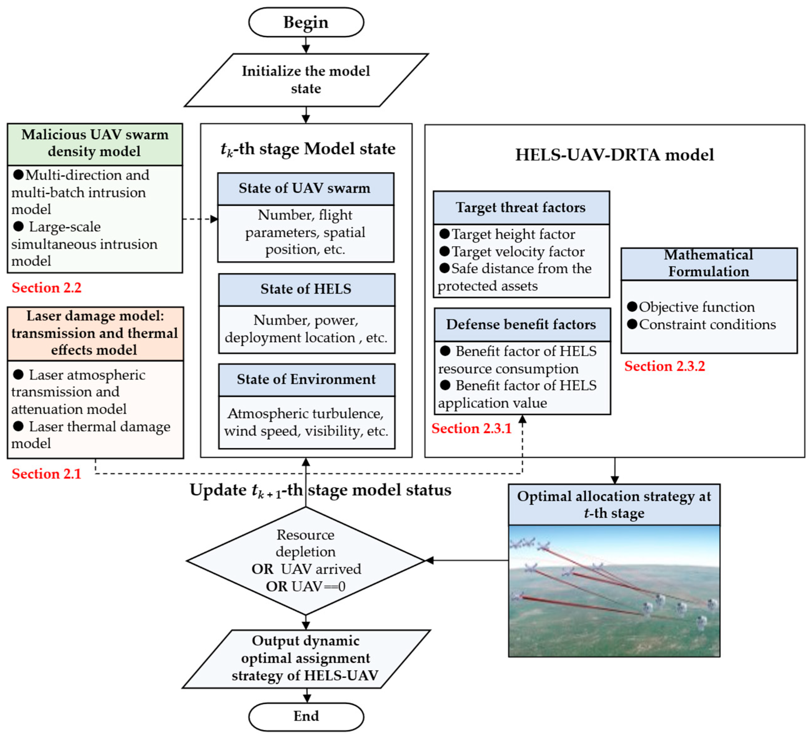
Figure 1. Framework of the HELS–UAV–DRTA model.
Aerospace 12 00729 g001
Figure 2. The process of laser atmospheric transmission.
Aerospace 12 00729 g002
Figure 3. Schematic diagram of HELS irradiating UAV.
Aerospace 12 00729 g003
Figure 4. Schematic diagram of the laser thermal damage effect.
Aerospace 12 00729 g004
Figure 5. Laser damage time vs. distance under different atmospheric conditions.
Aerospace 12 00729 g005
Figure 6. Laser damage time vs. various materials.
Aerospace 12 00729 g006
Figure 7. Malicious UAV swarm density model of multi-direction and multi-batch intrusion.
Aerospace 12 00729 g007
Figure 8. State coding network based on attention mechanism.
Aerospace 12 00729 g008
Figure 9. Architecture of the RND-based intrinsic reward module.
Aerospace 12 00729 g009
Figure 10. Architecture of MADDPG-IA.
Aerospace 12 00729 g010
Figure 11. The spatial situation after decision-making: (a) front view; and (b) top view.
Aerospace 12 00729 g011
Figure 12. Irradiation timing of each HELS agent.
Aerospace 12 00729 g012
Figure 13. Solving the HELS–UAV–DRTA problem in different scenarios based on the MADDPG-IA: (a) small-scale, sunshine, weak turbulence, and desert; (b) large-scale, light haze, medium turbulence, and rural; (c) small-scale, light haze, medium turbulence, and rural; (d) large-scale, sunshine, weak turbulence, and desert; (e) small-scale, sunshine, weak turbulence, coastal (rural–marine); and (f) large-scale, sunshine, weak turbulence, and coastal (rural–marine).
Aerospace 12 00729 g013aAerospace 12 00729 g013b
Figure 14. Rewards for each HELS agent and sum rewards.
Aerospace 12 00729 g014
Figure 15. Results of ablation experiments.
Aerospace 12 00729 g015
Figure 16. Algorithm comparison results: (a) small-scale; and (b) large-scale.
Aerospace 12 00729 g016
Table 1. Simulation parameter setting.
CategoryAttributeValue
HELS parametersThe number of HELS nHELS2 (small-scale), 5 (large-scale)
Initial emitted power P020 kW~50 kW
Battery magazine tbattery200 s, 250 s
Wavelength λ1.064 μm
Diameter of telescope aperture D0.6 m
Initial beam quality factor β01
Maximum detection distance7.5 km~8 km
UAV parametersThe number of UAVs nUAV10 (small-scale), 50 (large-scale)
Attack direction2 (small-scale), 5 (large-scale)
Target flow density parameterμ = 1, σ = 2
Flight speed vj0.02 km/s~0.03 km/s
Flight height hj0.2 km~0.8 km
Material and thickness of the irradiated area2024 Al, zd = 5 mm (thermophysical properties are from Ref. [55])
Atmospheric parametersAtmospheric turbulence Cn2(0)1 × 10⁻¹⁷, 1 × 10⁻¹⁵
Aerosol model constant K2.828 (rural), 2.496 (desert), 4.453 (maritime)
Visibility ν 10 km (sunshine), 5 km (light haze)
Wind speed vg5 m/s
MADDPG-IA parametersSize of the experience pool1 × 106
Batch size2048
Max episode2000
Actor network learning rate1 × 10−3
Critic network learning rate1 × 10−3
Soft update parameter ϖ 1 × 10⁻²
Discount factor γ0.95
Table 2. Full statistical analysis of damage rate in large-scale scenarios.
EnvironmentMADDPG-IA
Mean ± Std (%)
Traditional Strategy
Mean ± Std (%)
MADDPG-IA
95% CI
Rural (sunshine)99.65 ± 0.3272.64 ± 3.21[99.54, 99.76]
Desert (light haze)79.37 ± 2.1551.29 ± 4.87[78.82, 79.92]
Coastal (sunshine)91.25 ± 1.7867.38 ± 3.95[90.82, 91.68]
Note: The standard deviation (Std) and confidence interval (CI) are calculated based on 100 independent runs with unique random seeds, ensuring no overlap in initial conditions or environmental stochasticity. Confidence intervals were calculated via bootstrap resampling (n = 1000 samples).
Table 3. The results of the parameter variation experiment.
ParametersDamage Rate (Mean ± Std)
HELS number3 HELS
72.3% ± 3.5%
4 HELS
89.5% ± 2.1%
5 HELS
99.6% ± 0.3%
6 HELS
99.7% ± 0.25%
7 HELS
99.8% ± 0.2%
Average laser power20 kW
65.1% ± 4.1%
25 kW
72.5% ± 3.1%
30 kW
85.2% ± 2.3%
40 kW
99.7% ± 0.21%
50 kW
99.9% ± 0.05%
UAV number10
100% ± 0%
30
99.9% + 0.03%
50
99.6% ± 0.3%
70
89.3% ± 2.5%
100
62.7% ± 4.8%
Atmospheric
turbulence
1 × 10⁻¹⁷
99.6% ± 0.3%
5 × 10⁻¹⁶
95.4% ± 1.5%
1 × 10⁻¹⁵
79.4% ± 2.1%
5 × 10⁻¹⁵
68.2% ± 3.8%
5 × 10⁻¹⁴
58.7% ± 5.2%
Disclaimer/Publisher’s Note: The statements, opinions and data contained in all publications are solely those of the individual author(s) and contributor(s) and not of MDPI and/or the editor(s). MDPI and/or the editor(s) disclaim responsibility for any injury to people or property resulting from any ideas, methods, instructions or products referred to in the content.