Article

Fast Buckling Analysis of Stiffened Composite Structures for Preliminary Aerospace Design

by
Dimitrios G. Stamatelos
1,* and
George N. Labeas
2
1
Laboratory of Strength of Materials, Division of Aeronautics, Applied Mechanics and Infrastructure, Department of Aeronautical Sciences, Hellenic Air Force Academy, 13671 Athens, Greece
2
Laboratory of Technology and Strength of Materials, Department of Mechanical Engineering and Aeronautics, University of Patras, 26500 Rion, Greece
*
Author to whom correspondence should be addressed.
Aerospace 2025, 12(8), 726; https://doi.org/10.3390/aerospace12080726
Submission received: 8 June 2025 / Revised: 4 August 2025 / Accepted: 9 August 2025 / Published: 14 August 2025
(This article belongs to the Section Aeronautics)

Abstract

Predicting buckling in large-scale composite structures is hindered by the need for highly detailed Finite Element (FE) models, which are computationally expensive and impractical for early-stage design iterations. This study introduces a macromodelling buckling framework that reduces those models to plate-level size without sacrificing accuracy. An equivalent bending stiffness matrix is derived from strain–energy equivalence, rigorously retaining orthotropic in-plane terms, bending–extensional coupling, and—crucially—the eccentricity of compressive loads about an unsymmetrically stiffened mid-plane, effects overlooked by conventional Parallel-Axis smearing. These stiffness terms contribute to closed-form analytical solutions for homogeneous orthotropic plates, providing millisecond-level evaluations ideal for gradient-based design optimisation. The method is benchmarked against detailed FE simulations of panels with three to ten stringers under longitudinal and transverse compression, showing less than 5% deviation in critical load prediction. Its utility is demonstrated in the sizing optimisation of the upper cover of a scaled Airbus A330 composite wing-box, where the proposed model explores the design space in minutes on a standard workstation, orders of magnitude faster than full FE analyses. By combining analytical plate theory, enhanced smearing, and rapid optimisation capability, the framework provides an accurate, ultra-fast tool for buckling analysis and the preliminary design of large-scale stiffened composite structures.

1. Introduction

Composite materials are increasingly being used in almost all industrial sectors, such as aerospace, aeronautics, and marine and civil engineering. As an example, the percentage of composite materials in primary aeronautical structures is about 25% for the Airbus 380 aircraft (https://www.airbus.com/en/products-services/commercial-aircraft/passenger-aircraft/a380, accessed on 12 June 2025) and 50% for the new Boeing 787 aircraft. An interesting and complex structural design problem is the optimum sizing of stiffened composite panels of large structural components under compressive loading. This is due to the need for an accurate calculation of the critical buckling loads of stiffened panels comprising the large components, which requires modelling the different complex stiffener geometries (having open or closed cross-sections), as well as the skin stiffener interfaces. In the stage of initial and preliminary design of large-scale structures, modelling the stiffener geometry and its connection to the skin would result in a computational model of the order of millions of degrees of freedom, requiring a significantly high model development and solution effort. Furthermore, changing the design parameters and performing numerous iterations with such a detailed, large-scale numerical model is rather impractical using standard computational resources. In these cases, the development and application of macromodelling-based engineering methods for simplifying the buckling problem solution of stiffened panels enables a fast and accurate calculation of the critical buckling load and simplifies the preliminary design optimisation and sizing procedure of composite large-scale structures.
In general, the buckling problem of stiffened panels has been mainly approached numerically using the FE method [1,2,3,4,5,6,7,8,9,10,11,12,13] or semi-analytically [14,15,16], as well as by analytical approaches [6,11,17,18,19,20,21]. The FE method and the semi-analytical approach require substantial modelling and solution time and effort for solving buckling problems of large-scale structures. As a result, these solution methods are not suitable for implementation in a preliminary design optimisation loop, while analytical closed-form solutions are preferred for this design stage.
Closed-form solutions that take into account stiffeners have been derived for specific cases only [18,22], and they cannot cover the wide range of boundary and loading conditions that exist in a large-scale structure. To overcome this gap, the critical buckling loads of stiffened panels are mainly estimated using empirically or experimentally derived correction factors applied to the closed-form solution of unstiffened panels [23]. Such an example is the work carried out by Herbeck [24], who estimated conservatively the critical buckling load of the covers of an outer composite wing, considering the “combined buckling hypothesis” and empirical closed-form formulations for unstiffened plates. Fast, closed-form solutions that balance accuracy and computational efficiency for early-stage design have seen considerable advances over the last decade. Ritz-based closed-form models specifically tailored to omega-stringer stiffened composite panels have been extensively validated against FE analyses, successfully capturing local buckling under compression and combined compression-shear loads with millisecond-level evaluation times suitable for optimisation workflows [25,26,27,28]. These methods, while efficient and precise for common stiffener geometries, often focus on local buckling modes and idealised boundary conditions, limiting their direct applicability to more complex or large-scale structures. Several efforts have also targeted rapid analytical tools to facilitate sizing and optimisation by combining closed-form buckling predictions with gradient-based methods to explore the design space at different levels [29,30].
To take into account efficiently the stiffeners’ effect on large-scale structure panels, a smearing approach can be applied. In the Smearing Stiffener Method (SSM), the stiffened panel is mathematically converted to an unstiffened homogeneous panel of uniform thickness, with equivalent orthotropic or anisotropic stiffness properties. Smearing the stiffeners into an unstiffened panel has been successfully applied to solve mainly bending and in-plane stress and limited buckling analysis problems, while none of them have been applied in large-scale structures.
A characteristic example of a buckling problem solved by the smearing approach is [31], which incorporated the local stress distribution around the skin–stiffener junction into the smeared stiffener method using the First Order Shear Deformation Theory (FSDT). Another research using the smeared stiffener approach was performed by Phillips and Gurdal [32], who analysed the forces on a symmetrical unit cell that represents a whole grid network of a stiffened isotropic/orthotropic panel and calculated the equivalent stiffness parameters. Reddy et al. [33] used the smeared stiffener approach to perform buckling analysis on grid-stiffened cylindrical panels using an energy approach (Galerkin). A more generic smeared model for determining the global buckling of a stiffened composite anisotropic/orthotropic cylindrical shell was developed by Kidane et al. [34]. Xu et al. [35] developed an effective smeared stiffener method that accounts for skin–stiffener interactions based on an improved mechanical hypothesis, providing enhanced accuracy and computational efficiency for global buckling analysis of grid stiffened composite panels. Wang et al. [36] proposed a numerical-based smeared stiffener method using asymptotic homogenisation to improve the prediction accuracy of buckling loads in grid-stiffened composite cylindrical shells, demonstrating advantages over traditional smeared methods and FEM in efficiency. Improvements to the smearing technique for cross-stiffened thin rectangular plates, particularly including the effect of parallel stiffeners, were introduced by Luan et al. [37], resulting in a better accuracy of predicted natural frequencies and forced responses. Hao et al. [38] applied the SSM in a hybrid optimization framework for hierarchical stiffened shells, combining SSM efficiency with FEM accuracy to account for imperfection sensitivity. Similarly, Wang et al. [39] presented a hybrid analysis and optimisation approach for hierarchical stiffened plates, utilizing asymptotic homogenisation to reduce computational costs while maintaining accuracy.
Complementary smeared stiffener approaches have been further proposed to address global buckling behaviour in grid- or sub-stiffened composite panels, incorporating orthotropic material behaviour through a stiffener configuration parameter vector, [35]. In a related effort, Ye et al. [40] investigated the improvement of structural efficiency in composite stiffened panels by optimising a new structural form known as ‘sub-stiffeners’. To reduce computational cost, Meng et al. [41] proposed an objective-pursuing learning method that combines the advantages of the smeared stiffener method and the Kriging model for cylindrical stiffened shells. However, these formulations may not fully capture critical effects such as bending–extensional coupling, bending–shear coupling, and eccentric loading about unsymmetrical stiffened mid-planes. While such effects are often underrepresented, [42] highlight the broader need for advanced predictive models in realistic aerospace structures, where achieving maximum weight reduction and structural efficiency in composite stiffened panels remains a central design goal.
In this work, an equivalent bending stiffness matrix is formulated, explicitly including the in-plane and coupling stiffness terms, which significantly simplifies the buckling solution via analytical closed-form solutions. Unlike previous SSMs—including those by [35,36], which rely on numerical homogenisation or semi-analytical approaches—this formulation enables a fully analytical treatment.
Additionally, this study advances the state of the art by accounting for load eccentricity relative to the unsymmetrically stiffened panel midplane, a factor not addressed by existing smearing approaches. Moreover, the developed macromodelling framework enables the direct mathematical solution of the buckling problem for stiffened panels by equating the strain energy of the stiffened panel to that of a hypothetical homogeneous panel, thereby calculating the equivalent stiffness matrix. This approach contrasts with hybrid or numerical methods (e.g., [38,39]) that combine smeared models with FE analysis, providing enhanced computational efficiency and analytical clarity.
The energy approach employed for the developed operation results in equivalent bending stiffness terms, which take into account the bending–extensional stiffness coupling of the structural anisotropic panel. The aforementioned is not considered in the conventional Parallel Axis Theorem (PAT) approach, [43]. Additionally, the equivalent loading is calculated considering the load eccentricity to the unsymmetrically stiffened panel midplane (also ignored using PAT).
Moreover, unlike the traditional Reduced Bending Stiffness (RBS) method [44], which often neglects load eccentricity and bending–extensional coupling, the presented macromodelling framework rigorously retains these effects through strain energy equivalence. This leads to more accurate predictions for stiffened composite structures by capturing orthotropic in-plane behaviour, coupling effects, and load eccentricity, which are typically overlooked in standard RBS methods. Following the validation of the macromodelling methodology, it is applied to the sizing optimisation of the upper cover of a scaled Airbus A330 composite wing box structure.
The paper begins by formulating a macromodelling framework for stiffened composite panels, where an equivalent bending stiffness matrix and load vector are derived using strain energy equivalence to capture orthotropic behaviour accurately, bending–extensional coupling, and load eccentricity effects (Section 2). The accuracy of this reduced-order approach is then assessed through FE analysis, using a high-fidelity reference model to benchmark the predicted buckling loads under both longitudinal and transverse compression (Section 3). A detailed description of the FE model setup, material assumptions, and comparison results for different loading cases is provided to validate the model’s reliability (Section 3.1, Section 3.2 and Section 3.3). The validated macromodel is then integrated into a sizing optimisation framework for a composite aircraft wing, where it enables the rapid evaluation of design configurations under buckling constraints (Section 4). This includes the modelling of a large-scale wing structure, development of a simplified FE model, and implementation of the optimisation loop (Section 4.1, Section 4.2 and Section 4.3). The paper concludes with key findings and highlights the potential of the proposed method for efficient early-stage structural design (Section 5).

2. Calculation of Equivalent Stiffness Matrix and Load Vector of Composite Stiffened Panels

In the smeared stiffener approach, the stiffened panel is mathematically converted to an unstiffened homogeneous panel of equivalent stiffness, as shown in Figure 1. The equivalent stiffness is conventionally calculated by the PAT, which can be used to calculate the stiffness of a skin-stiffener assembly to any arbitrary axis parallel to its middle plane, as described by Tsai et al. in [43].
In Figure 1, N x , N y are the in-plane normal forces per unit width in x and y directions, respectively, for a stiffened panel, while N x e q , N y e q are the in-plane normal forces per unit width in the x and y directions, respectively, for a homogeneous panel.
The present derivations are based on the assumptions of Classical Laminate Plate Theory (CLPT). The kinematic hypotheses follow the Kirchhoff–Love assumptions, whereby normals to the mid-surface remain straight and normal after deformation and do not experience transverse stretching. As a result, the transverse normal strain ( ε z 0 ) and the transverse shear strains ( γ y z 0 and γ x z 0 ) are assumed to be zero. This reduces the six strain components to the in-plane terms ε x 0 , ε y 0 and γ x y 0 . Additionally, small strain and linear elasticity assumptions are considered, and the resulting stress–strain relations are given by the constitutive equations in (1).
N x N y N x y = A 11 A 12 A 16 A 12 A 22 A 26 A 16 A 26 A 66 ε x 0 ε y 0 γ x y 0 + B 11 B 12 B 16 B 12 B 22 B 26 B 16 B 26 B 66 k x k y k x y M x M y M x y = B 11 B 12 B 16 B 12 B 22 B 26 B 16 B 26 B 66 ε x 0 ε y 0 γ x y 0 + D 11 D 12 D 16 D 12 D 22 D 26 D 16 D 26 D 66 k x k y k x y
where N x y is the in-plane shear force per unit width. M x and M y are the bending moments per unit width about the x and y axes, and M x y is the twisting per unit width. k x and k y are the curvatures of the laminate about the x and y axes, and k x y is the twist curvature. Finally, A i j , B i j , and D i j are the in-plane, coupling, and bending stiffness terms, respectively.
In the proposed energy-based macromodelling methodology, the equivalent bending stiffness and the equivalent loading system, resulting from the eccentric application of loads on the stiffened panel, are calculated by equating the strain and potential energy of the stiffened panel to those of a homogenised panel.
The total potential energy Π of an elastic structure is the sum of the work done by external forces plus the strain energy stored in the structure. The total potential energy Π of a stiffened panel consists of the flat skin’s and stiffeners’ potential energy, as it is shown in Equation (2).
Π = U s k i n + V s k i n + U s t i f f e n e r + V s t i f f e n e r
The bending stiffness matrix terms ( D i j ) are written to the panel’s neutral surface for expressing the strain energy U s k i n of an orthotropic flat skin of a stiffened panel. The panel’s neutral surface is chosen as the reference plane because, according to the PAT, the mechanical coupling term in the longitudinal direction ( B 11 ) vanishes when the stiffness of the skin–stiffener assembly is calculated about this plane. However, the selection of this neutral surface results in extensional and coupling terms to the rest of the panel bending stiffness terms. These terms yield from the geometrical unsymmetry of the stiffeners with respect to the panel midplane. Taking into account balanced composite plates with flexural orthotropy, the terms A 16 = A 26 =   B 16 = B 26 = D 16 = D 26 of Equation (1) become zero. As a result, the equation of the flat’s skin strain energy can be written as presented in Equation (3).
U s k i n = 1 2 0 a 0 b { A 11 u s k i n 0 x 2 + 2 A 12 u s k i n 0 x v s k i n 0 y + A 22 v s k i n 0 y 2 + A 66 u s k i n 0 y + v s k i n 0 x 2 2 B 12 v s k i n 0 y 2 w s k i n 0 x 2 + u s k i n 0 x 2 w s k i n 0 y 2 B 22 v s k i n 0 y 2 w s k i n 0 y 2 4 B 66 2 w s k i n 0 x y u s k i n 0 y + v s k i n 0 x + D 11 2 w s k i n 0 x 2 2 + 2 D 12 2 w s k i n 0 x 2 2 w s k i n 0 y 2 + D 22 2 w s k i n 0 y 2 2 + 4 D 66 2 w s k i n 0 x y 2 } dy dx
In Equation (3), u s k i n 0 , v s k i n 0 , and w s k i n 0 are the skin’s middle-plane displacements, whereas a and b are the dimensions of the orthogonal panel in the x and y directions. To eliminate the in-plane displacement terms from Equation (3), Equation (1) is solved for the in-plane strains, expressing them in terms of the out-of-plane displacements. ε x 0 = u s k i n 0 x ,   ε y 0 = v s k i n 0 y and γ x y 0 = u s k i n 0 x + v s k i n 0 y , i.e.,
ε x 0 = u s k i n 0 x = A 22 N x A 12 N y A 22 A 11 A 12 2 + A 12 B 12 A 22 A 11 A 12 2 2 w s k i n 0 x 2 A 22 B 12 A 12 B 22 A 22 A 11 A 12 2 2 w s k i n 0 y 2
ε y 0 = v s k i n 0 y = A 11 N y A 12 N x A 22 A 11 A 12 2 A 11 B 12 A 22 A 11 A 12 2 2 w s k i n 0 x 2 A 11 B 22 A 12 B 12 A 22 A 11 A 12 2 2 w s k i n 0 y 2
γ x y 0 = u s k i n 0 x + v s k i n 0 y = N x y A 66 B 66 A 66 2 2 w s k i n 0 x y
By substituting Equations (4)–(6) into Equation (3), the strain energy of the skin U s k i n can be expressed as a function of the out-of-plane displacements w s k i n 0 only. The final expression of the U s k i n is available in Appendix A.
The innovation of this substitution is that the strain energy of the stiffened panel skin with respect to its neutral surface, which normally should include in-plane displacements, is written as a function of the out-of-plane displacements only. The last substitution enables the equation of the stiffened panel’s skin strain energy to the respective hypothetical homogenized flat panel, since both expressions are functions of the out-of-plane displacements.
The terms in Equations (4)–(6) that depend on N x , N y , and N x y can be neglected, as they are significantly smaller—typically by one to two orders of magnitude—than the other dominant terms in the same equations. This simplification was further supported by sensitivity studies, which confirm that omitting these terms has a negligible impact on the buckling load prediction.
The strain energy U s t i f f e n e r of the longitudinal stiffener in the buckled state is written as:
U s t i f f e n e r = Ε s t i f f e n e r a p p a r I y 2 j = 1 j = N s t i f f e n e r 0 a 2 w s k i n 0 x 2 2 y = b j N s t i f f e n e r + 1 d x
In Equation (7), Ε s t i f f e n e r a p p a r is the apparent modulus of elasticity of the composite material as calculated by the formulation Ε s t i f f e n e r a p p a r = 1 t s t i f f e n e r · a 11 s t i f f e n e r , where a 11 s t i f f e n e r is the ( 1,1 ) entry of the inverse of the A-matrix. I y and N s t i f f e n e r are the second moment of inertia about the neutral surface of the skin–stiffener assembly and the number of stiffeners, respectively.
The work done ( V s k i n ) during buckling by the compressive forces N x acting in the x direction (Figure 1) and the compressive forces N y acting in the y direction is written as:
V s k i n = 1 2 0 a 0 b N x w s k i n 0 x 2 + N y w s k i n 0 y 2 dy dx
In case the stiffened panel is under pure axial compression, the term N y vanishes.
The work done ( V s t i f f e n e r ) during buckling by the axial compressive force F that acts on the longitudinal stiffeners is:
V s t i f f e n e r = j = 1 j = N s t i f f e n e r F 2 0 a w s k i n 0 x 2 y = j b N s t i f f e n e r + 1 d x
By assuming that the stiffeners and the skin experience the same strain, the force F applied to the stiffeners is proportional to the in-plane normal load N x acting on the skin as follows.
F = N s t i f f e n e r N x Ε s t i f f e n e r a p p a r A s t i f f e n e r E s k i n a p p a r t s k i n
In Equation (10), E s k i n a p p a r is the apparent skin’s elasticity modulus, and it is calculated by the formulation Ε s k i n a p p a r = 1 t s k i n · a 11 s k i n , where a 11 s k i n is the ( 1,1 ) entry of the inverse of the A-matrix and A s t i f f e n e r and t s k i n are the stiffeners’ area and the skin’s thickness, respectively.
The equivalent total potential energy, Π h o m o g e n i z e d , of an orthotropic flat panel can be expressed by Equation (11).
Π h o m o g e n i z e d = U h o m o g e n i z e d + V h o m o g e n i z e d
In Equation (11), U h o m o g e n i z e d is the strain energy of the homogeneous panel, Equation (12), and V h o m o g e n i z e d is the work done by the compressive forces, Equation (8).
U h o m o g e n i z e d = 1 2 0 a 0 b { D 11 e q 2 w s k i n 0 x 2 2 + 2 D 12 e q 2 w s k i n 0 x 2 2 w s k i n 0 y 2 + D 22 e q 2 w s k i n 0 y 2 2 + 4 D 66 e q 2 w s k i n 0 x y 2 } d y d x
In Equation (12), D i j e q are the equivalent bending stiffness terms of the homogenized panel.
By equating the strain energy and the work done by the compressive forces in the stiffened panel (which has been expressed as a function of the out-of-plane displacements only) to the respective energy of an equivalent homogeneous panel separately, using Equations (13) and (14), the equivalent bending stiffness terms and the equivalent loading system can be calculated.
U s k i n + U s t i f f e n e r = U h o m o g e n i z e d
V s k i n + V s t i f f e n e r = V h o m o g e n i z e d
More specifically, the expressions, which are multiplied by the partial derivatives of the out-plane displacements of the left-hand side of Equations (13) and (14), are equated with the respective expressions of the right-hand side. As a result, the equivalent bending stiffness matrix terms D i j e q , which yield for the homogenized panel, are presented in Equations (15)–(18). The equivalent bending stiffness matrix terms are calculated with respect to the middle plane of the homogeneous panel. The same concept is followed for calculating the equivalent loading N x e q , N y e q of the homogeneous panel, Equations (19) and (20).
D 11 e q = D 11 + d s k i n 2 A 11 + 2 Ε s t i f f e n e r a p p a r I y b j = 1 N s t i f f e n e r sin j π N s t i f f e n e r + 1 2 A 12 2 B 12 2 A 11 A 11 A 22 A 12 2 2 + A 22 A 11 2 B 12 2 A 11 A 22 A 12 2 2 + 2 B 12 2 A 11 A 11 A 22 A 12 2
D 12 e q = D 12 + A 12 2 B 12 A 11 A 22 A 12 2 A 12 B 12 A 11 B 22 A 11 A 22 A 12 2 A 12 B 12 A 11 B 22 A 11 A 22 A 12 2 A 11 B 12 A 22 A 11 A 22 A 12 2 B 12 2 A 12 B 12 A 11 B 22 A 11 A 22 A 12 2 + 1 2 A 11 B 22 B 12 A 11 A 22 A 12 2
D 22 e q = D 22 + A 11 A 12 B 22 A 22 B 12 A 11 A 22 A 12 2 2 + 2 A 12 A 12 B 22 A 22 B 12 A 11 A 22 A 12 2 A 12 B 12 A 11 B 22 A 11 A 22 A 12 2 + A 22 A 12 B 12 A 11 B 22 A 11 A 22 A 12 2 2 2 B 12 A 12 B 22 A 22 B 12 A 11 A 22 A 12 2 B 22 A 12 B 12 A 11 B 22 A 11 A 22 A 12 2
D 66 e q = D 66 + 3 B 66 2 A 66
N x e q = N x + N s t i f f e n e r N x Ε s t i f f e n e r a p p a r A s t i f f e n e r E s k i n a p p a r A s t i n 2 b j = 1 N s t i f f e n e r sin j π N s t i f f e n e r + 1 2
N y e q = N y
In Equation (15), d s k i n is the distance of the skin’s middle plane from the neutral axis of the skin-stiffener assembly.
The proposed approach is capable of taking into account the geometrical asymmetry on the stiffened panel stiffness properties, as well as the effect of the eccentrically loaded system of the stiffened panel, which are ignored using the conventional PAT. Therefore, the present macromodelling methodology allows for the application of closed-form buckling solutions of homogeneous orthotropic panels of various loading and boundary conditions for the solution of buckling problems of stiffened panels.
The most widely used solution for calculating the critical buckling load N c r of a rectangular orthotropic panel under biaxial loading with simply supported edges is given by Narita et al. [45], as shown by Equations (21) and (22):
N c r = λ D 0 a 2
λ = π 2 D 11 e q D 0 m 2 + 2 D 12 e q D 0 + 2 D 66 e q D 0 α b 2 n 2 + α b 4 D 22 e q D 0 n 4 m 2 1 + N y N x α b 2 n m 2
In Equation (22), D 0 = E 11 t 3 12 1 ν 12 ν 21 , while α, b, and t are the length of the unloaded edge, the length of the loaded edge, and the panel thickness, respectively, m and n are the numbers of longitudinal and transversal buckling half waves, respectively, and their values are such that yield the minimum value for N c r uniaxial loading may be treated by setting N y / N x = 0 in Equation (22). For the special case of isotropic panels, the panel stiffness parameters are D 11 = D 22 = D ,     D 12 = ν D ,     D 66 = 1 2   1 ν D . It should be noted here that in case the stiffened panel has other loading or boundary conditions, respective solutions may be applied, after its homogenization.

3. FEA Validation of Buckling Solutions for Orthotropically Stiffened Panels

A parametric study is performed, which examines a simply supported square geometrically asymmetrical stiffened panel with dimensions of 500 mm × 500 mm and 2 mm thickness. The panel is braced by equidistant blade stiffeners. The ratio of the stiffener bending stiffness to the skin bending stiffness varies from 0% to approximately 100%.
Orthotropic material properties are considered for both the stiffeners and the skins with lamination of [(0/90)2]s and [0/90]s for the panel and the stiffener, respectively. The ply thickness is 0.25 mm, while representative material elastic constants are used: E11 = 157,000 MPa, E22 = 8500 MPa, G12 = 4200 MPa, and v12 = 0.35.
To evaluate the limitations of the developed modelling approach concerning the number of stiffeners, panels containing three, five, and ten stiffeners are analysed. Two loading conditions are considered: longitudinal compression and transverse compression.

3.1. Detailed Description of the FE Model

A numerical solution of the buckling problem under consideration is obtained based on the commercial FE software ANSYS 14.0, [46]. The FE model is developed for comparison and validation purposes of the buckling loads obtained by the present macromodelling approach. An eigenvalue buckling analysis is performed to determine the critical buckling load. The orthotropic stiffened panel is modelled by the element type Shell 99, which is a linear layered structural shell with six degrees of freedom at each node.
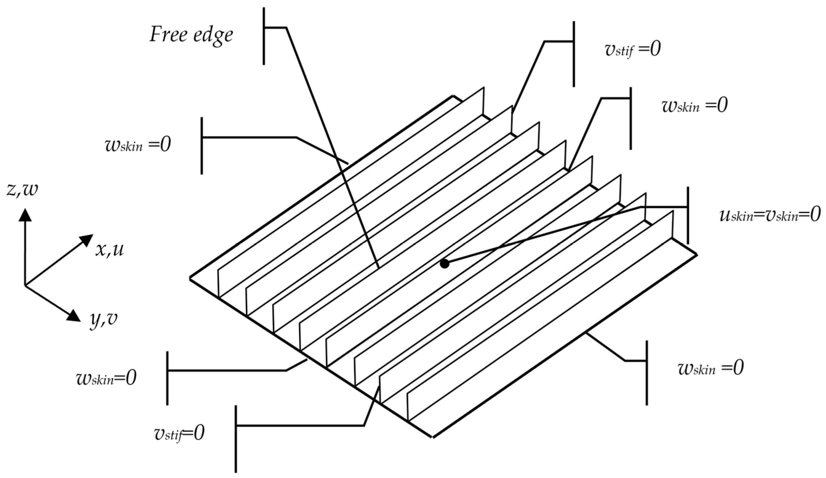
The examined stiffened panels are assumed to be simply supported. The boundary conditions applied to the FE model are demonstrated in Figure 2.
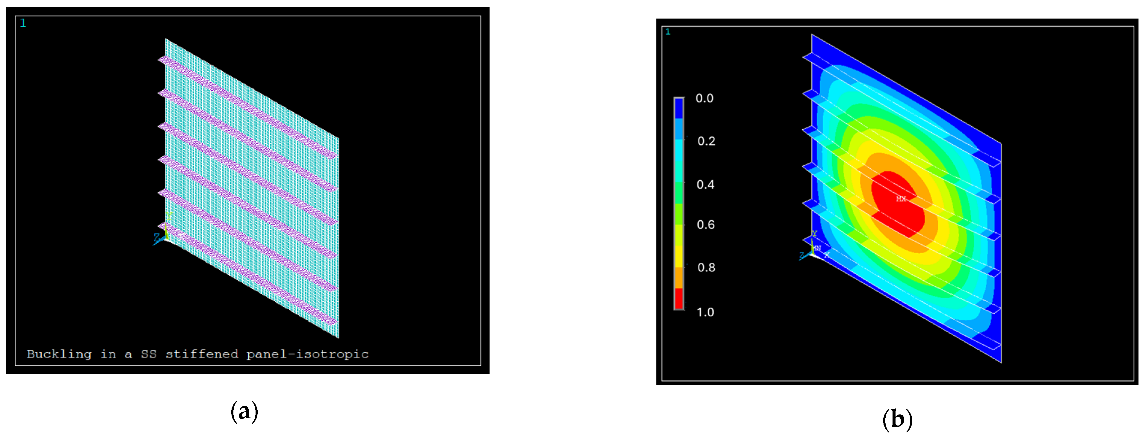
The developed FE model was validated for the buckling analysis setup using the case of a blade-stiffened isotropic square panel (α/b = 1) as reported by Stroud et al. in [2]. By refining the mesh density of Stroud’s FE model, an accurate reference model was generated for use in the following sections. In Figure 3a, the FE refined mesh discretisation of the panel is presented, together with the normalised out-of-plane displacement, Figure 3b, for the first buckling mode at a load of 176.09 N/mm.

3.2. Comparison Results for the Case of Uniaxial Compression

Orthotropic Material

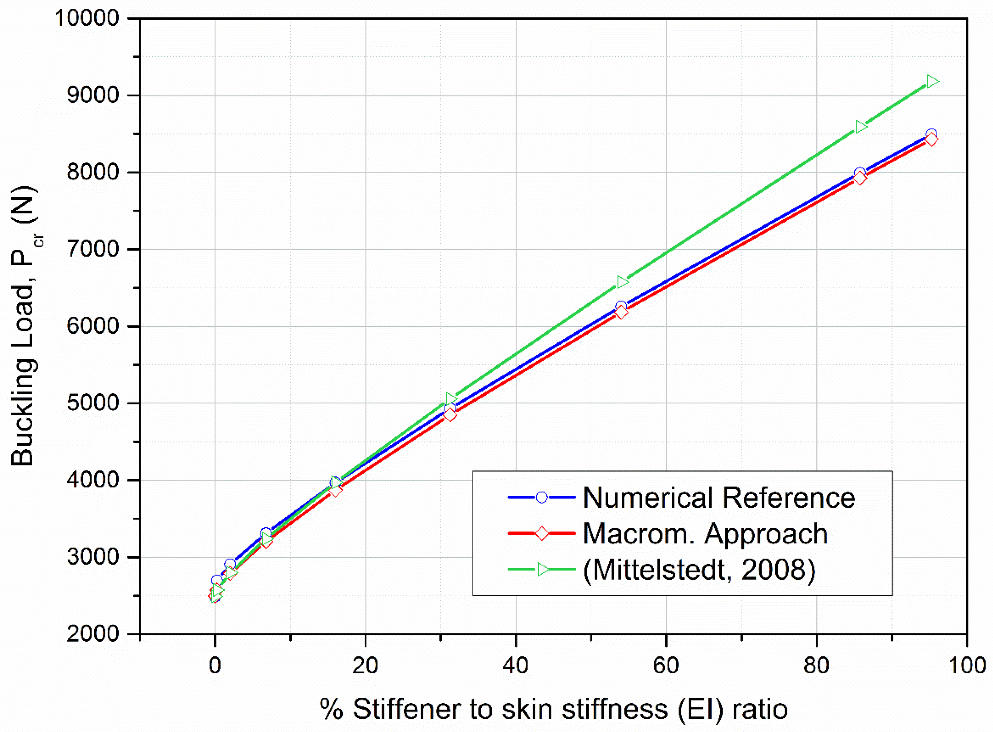
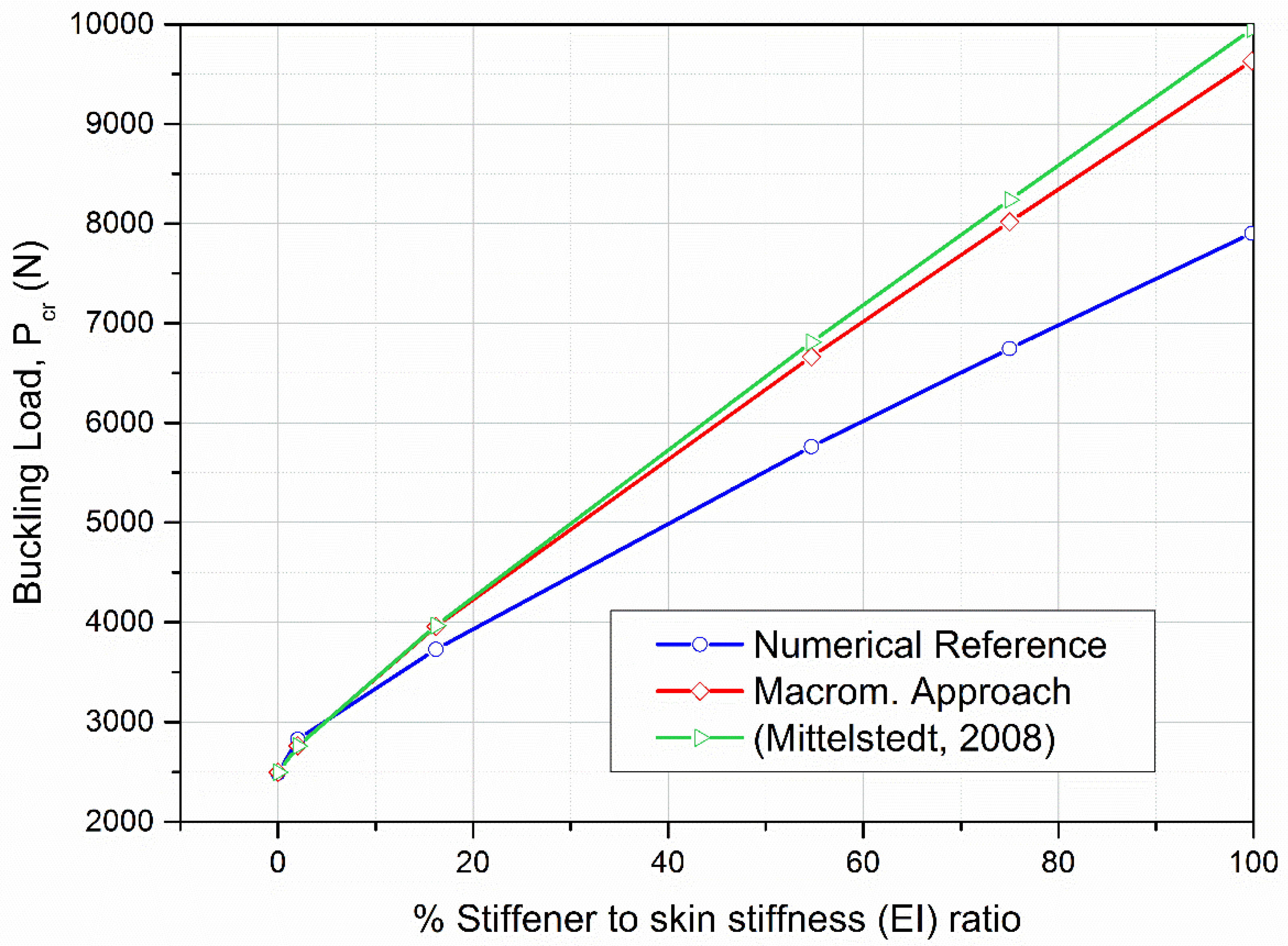
In Figure 4, Figure 5 and Figure 6, three different solutions for the calculation of the critical buckling loads of orthotropic panels braced by ten, five, and three equidistant stiffeners under uniaxial compression are presented. As clarified in Section 3.1, the ‘Numerical Reference’ corresponds to results obtained from ANSYS simulations, while the ‘Macromodel Approach’ represents the proposed analytical model developed in this study. To provide a comprehensive comparison, results from the ANSYS-based numerical model, the analytical micromodel/smearing, and Mittelstedt’s [17] closed-form solution are presented together in Table A1 (Appendix B) and Figure 4.
In Figure 4, it can be observed that the macromodelling approach predicts the numerical reference results with a maximum discrepancy of 2%. This good agreement is obtained because the anisotropy arising from the asymmetrical geometry, as well as the loading eccentricity with respect to the panel mid-plane, are taken into account via the proposed energy-based macromodelling approach. Another remark is that, as the examined stiffened panels buckle globally, even the low-stiffened ones, the macromodelling methodology is capable of accurately predicting the buckling load for all the stiffened panels. Regarding the solution time for a single stiffened panel of any geometry and number of stiffeners, ANSYS can return buckling results in under half a minute. The developed macromodelling code provides results for the same case in under 10 s.
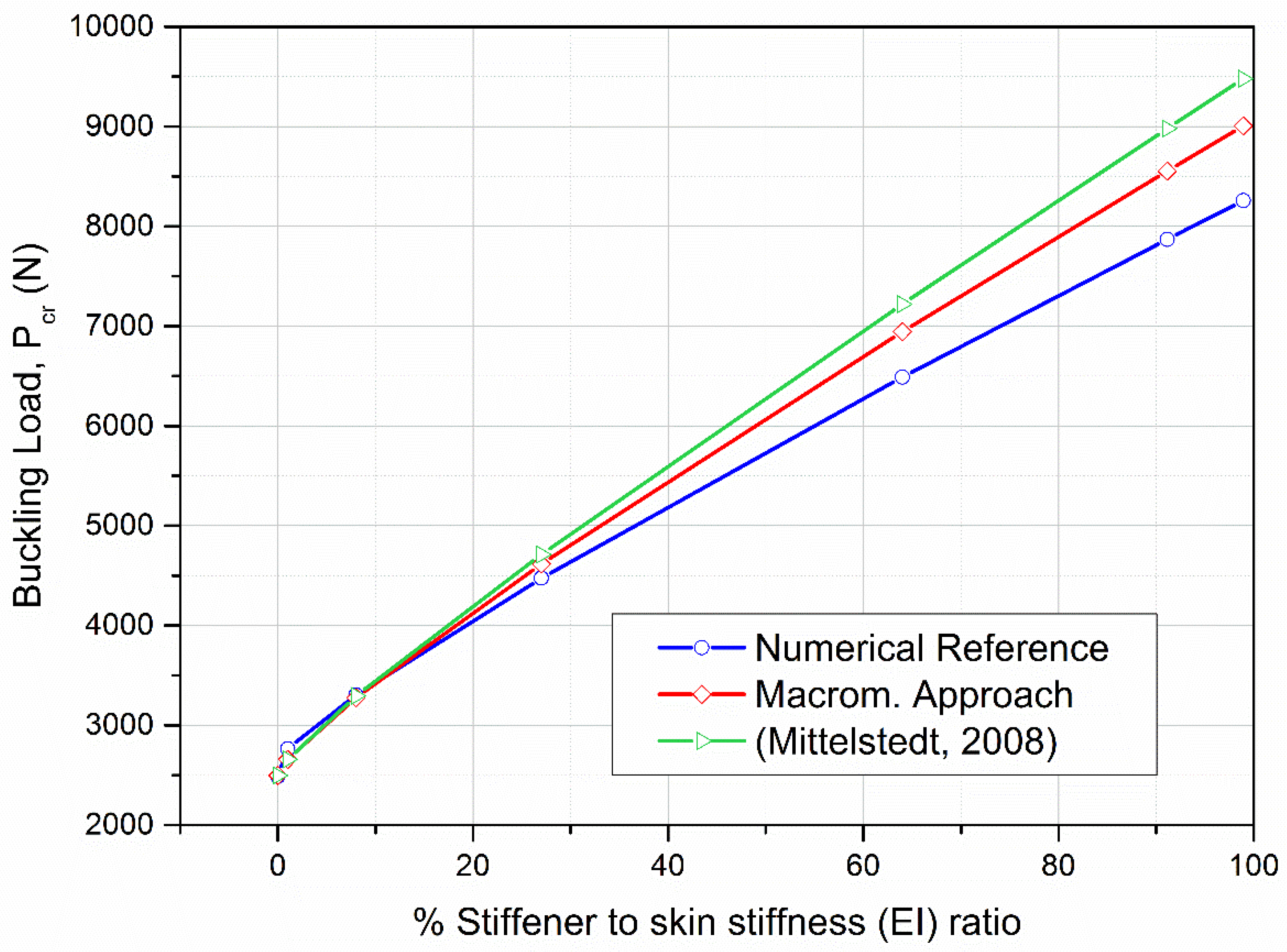
To further explore the efficiency of the developed macromodelling/smearing approach, panels with fewer stiffeners are examined for their stability under compressive loads. The cases examined are those of a stiffened panel braced by five and three equidistant stiffeners. In Table A2 (Appendix B) and Figure 5, the comparison of numerical, analytical, and macromodelling results for the five-stiffener configuration is presented.
Following Table A3 (Appendix B) and Figure 6 with the comparison of numerical, analytical, and macromodelling/smearing results for the three-stiffener configuration is presented.
From Figure 5 and Figure 6, it can be summarized that as the number of stiffeners decreases, the discrepancy between results obtained by the macromodelling approach and the detailed numerical approach increases. In more detail, the buckling load differences observed in stiffened panels with ten, five, and three stiffeners are 2%, 9%, and 22%, respectively. The inaccuracy of the present approach in panels with few stiffeners with high stiffness is because such panels experience local buckling modes before the global buckling occurs (especially when the stiffeners’ stiffness is increased). More specifically, the stiffened panels may buckle on the skin between the stiffeners, or buckling may occur on the stiffeners. As a result, the macromodelling approach is efficient only for cases where multiple stiffeners are attached to the skin, because in such cases the stiffened panel tends to buckle globally. Otherwise, discrepancies and inaccuracies in the prediction of the buckling load occur.

3.3. Compression in the Transverse Direction

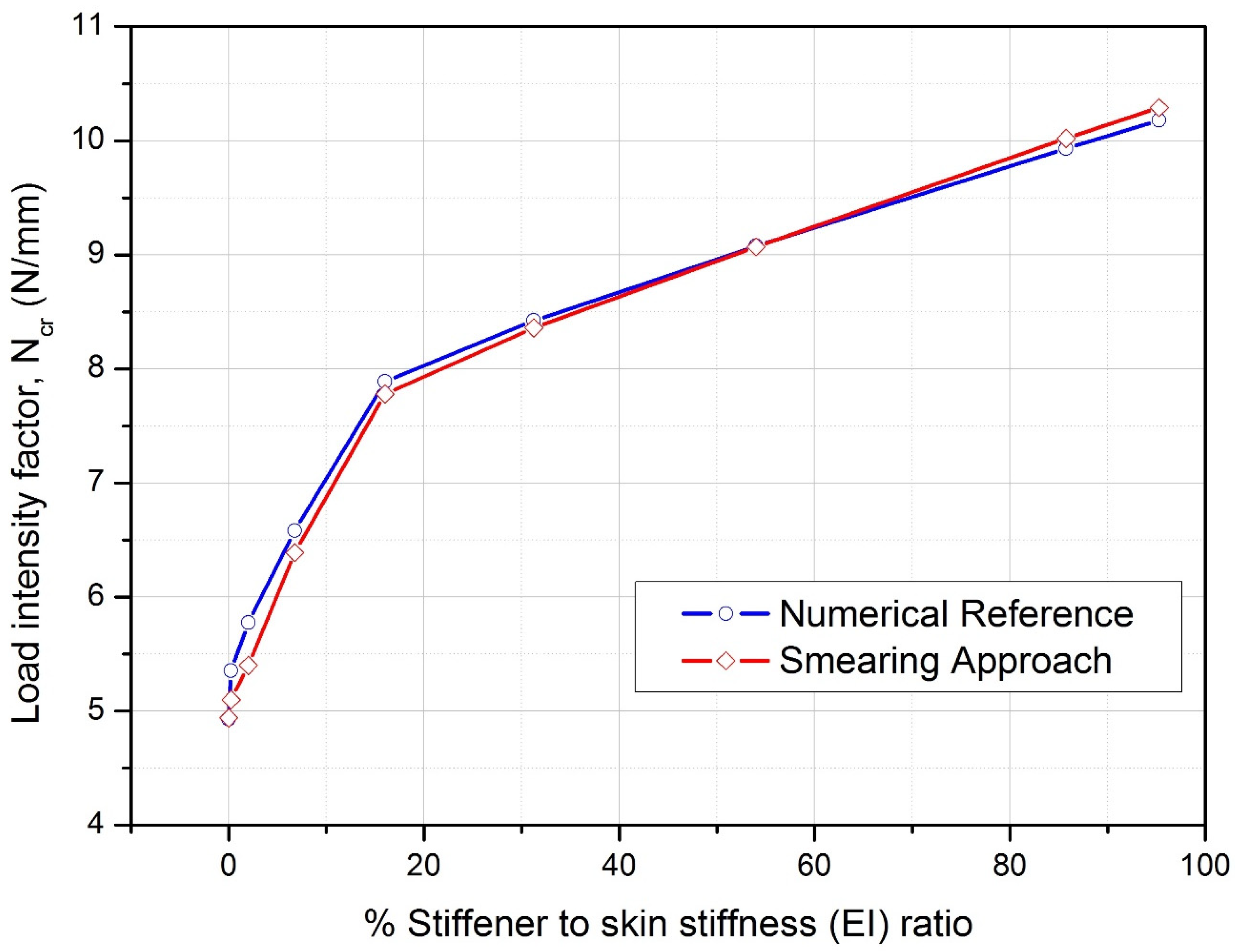
The critical buckling load results obtained by the proposed macromodelling/smearing approach are compared with the respective numerical reference results, for orthotropic stiffened panels under compression in the transverse direction (perpendicular to the stiffeners), Figure 7. To allow for the use of Equation (22), as in previous sub-sections, a high loading ratio of N y / N x = 100 is selected. It is assumed that this high loading ratio practically corresponds to the panel’s compression in the transverse direction, so the efficiency of the proposed macromodelling approach can be evaluated as presented in Table A4 (Appendix B) and depicted in Figure 7.
In Figure 7, the buckling load factors of transversely loaded stiffened panels calculated by the developed approach are compared with the respective reference numerical results. As can be observed from Figure 7, the numerical results do not exhibit a monotone behaviour. This phenomenon can be justified by studying the buckling modes that occur after each analysis. A single sine wave occurs in both the longitudinal and transverse directions for cases where the stiffener-to-skin ratio is up to 16%. For a higher stiffener-to-skin ratio (16% and above), a double sine wave, in the transverse direction, occurs. As a result, the switch of the buckling mode leads to the change in the slopes of the graphs in Figure 7.
Moreover, in Figure 7, it is noted that for a stiffener-to-skin ratio of 55% and above, the macromodelling approach predicts the buckling load in a non-conservative manner. This discrepancy occurs since the applied loads do not generate pure compression in the transverse direction, since the loading ratio is   N y / N x = 100 . It can be concluded that, despite the switch of the buckling mode and the un-conservative results for stiffener-to-skin ratios of 55% and above, the macromodelling approach demonstrates satisfactory agreement with the reference FE results for cases of transverse loading.

4. Sizing Optimization of a Composite Aircraft Wing

4.1. Modelling Approach for the Large-Scale Wing Structure

While the computation time for individual stiffened panels is already modest, the proposed macromodelling framework offers substantial time-saving and efficiency benefits when applied to large-scale structures composed of many such panels, such as aircraft wings. By enabling the construction of simplified FE models and leveraging closed-form expressions for rapid buckling load estimation, the approach significantly reduces model complexity without compromising accuracy. These advantages become particularly valuable during preliminary design stages, where geometry is still evolving and multiple design iterations are required. In contrast to detailed CAD/CAE workflows—which demand high-fidelity geometry and fine meshing—the macromodelling framework supports fast, buckling-driven resizing and mass estimation while avoiding the computational burden and manual effort associated with modelling each stiffener individually. This makes the method not only scalable and practical but also well-suited for early design environments where speed, flexibility, and informed trade-offs are essential.
To this end, the efficiency of the developed macromodelling approach is demonstrated in the sizing optimisation procedure of a composite aircraft wingbox, comprising 25 composite stiffened panels. The wingbox considered has the exact geometry of an Airbus A330 airliner wing, scaled at 70% of its original size, as a representative large-scale composite wing structure that continues to be relevant for validating generic design methodologies for research purposes. The length of the analysed wing is 21 m (wingspan of 44.95 m), with a total wing area of 94 m2. It is well known that the upper cover of a wing is subjected mainly to compressive loads during flight, which may lead to panel buckling. The optimisation approach followed in the present problem comprises three modules. Initially, a simplified parametric FE model of the entire aircraft wing is developed. The model refinement is up to the level of a stress-check model, implying that no stiffener is explicitly modelled; therefore, panel buckling cannot be calculated.
To validate the developed FE model of the wing structure, both accuracy and mathematical checks were performed according to [47]. A mesh convergence study was conducted to determine the optimal element size, ensuring acceptable element quality metrics, including aspect ratio, coordinate system alignment, etc. Following these accuracy checks, mathematical validations were carried out, including: (a) a free-free modal analysis to confirm structural connectivity, (b) unit gravity load tests in the x, y, and z directions, and (c) unit enforced displacement tests.
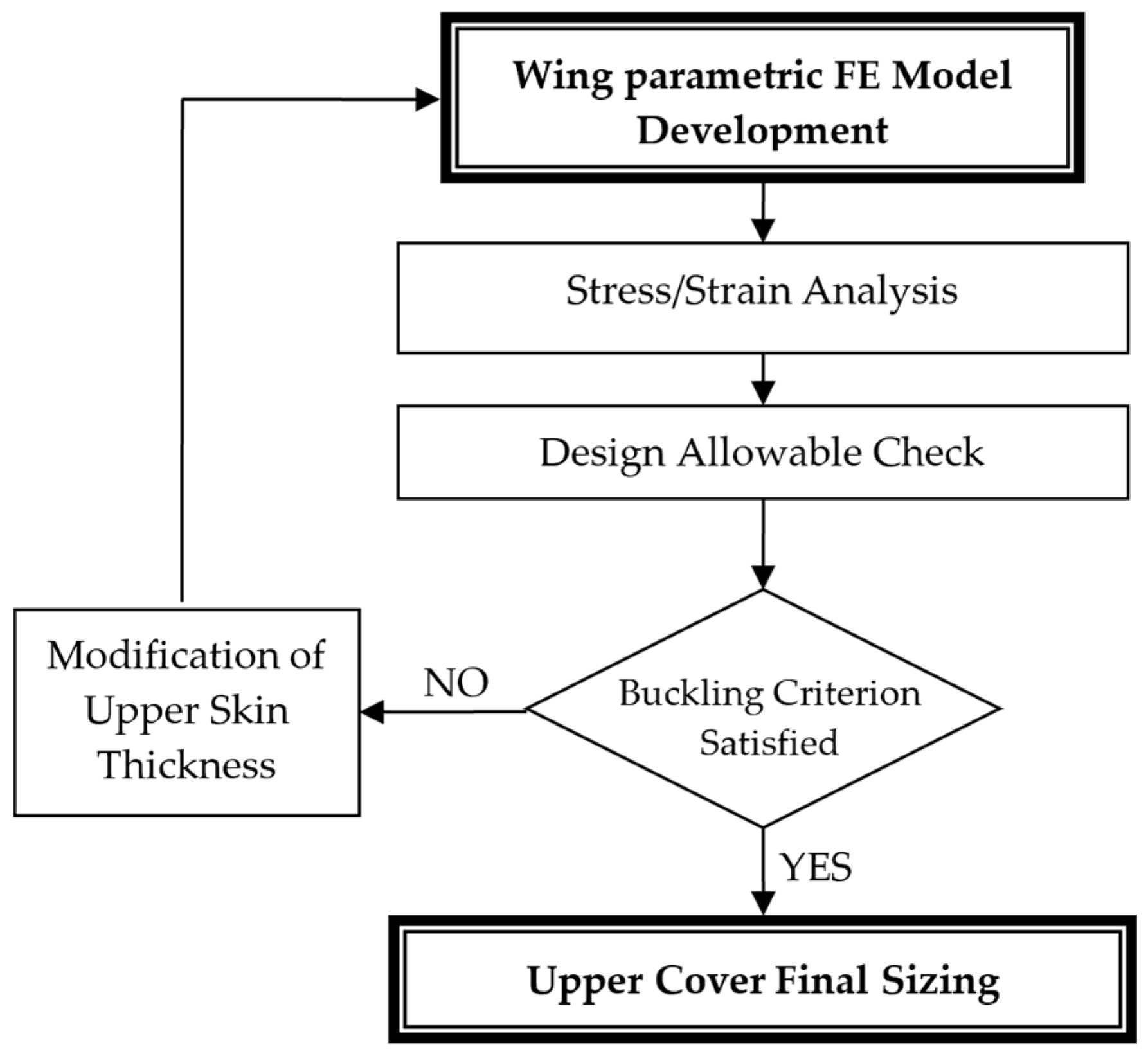
Solution of this global simplified model leads to the calculation of the compressive loading of each stiffened panel, which is calculated by the macromodelling approach described in Section 3. Finally, an optimisation loop is executed using a buckling constraint, which results in the optimum sizing of the wing’s upper cover. The flowchart of the optimization approach followed is presented in Figure 8. It should be emphasized that in case the model refinement would be of that level, where the critical buckling load of the stiffened panels would be reliably computed, the model size would be of the order of many thousands of elements; this can be simply calculated by considering that each of the 25 stiffened panels would comprise approximately 2000 elements, as it should have the minimum mesh refinement of the panel shown in Figure 3.

4.2. Description of the Simplified FE Wing Model

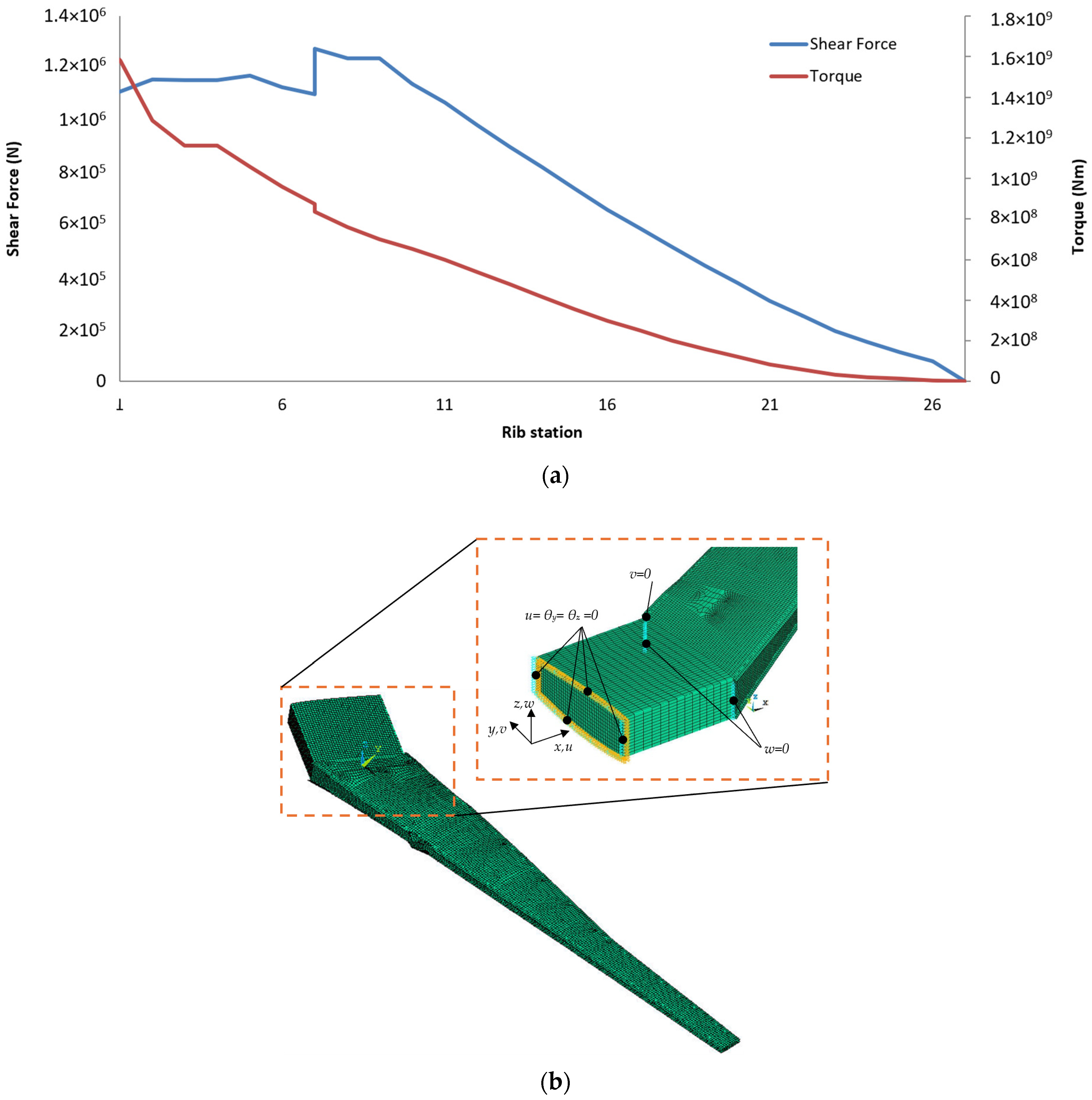
The simplified parametric FE model, shown in Figure 9, consists of shell (Shell181) and link (Link8) elements to determine the loads exerted at the upper cover. The analysis focuses on the most critical wing loading scenario, which is provided by Airbus-UK, considering aerodynamic lift and drag pressures in combination with the powerplant weight, Figure 9a. Secondary loading conditions—such as landing gear forces and additional aerodynamic effects—are excluded from this analysis. The wing loads are applied as concentrated forces and moments at nodes positioned at each rib station. These loads are then distributed around the rib perimeter using RBE3 interpolation elements. An extensive description of the FE model is documented in [48]. Additionally, the scaled wingbox is restrained as shown in Figure 9b, according to Airbus-UK guidelines.
The apparent material properties of the composite lay-up, as provided by Airbus-UK, for the spars and ribs, are E11 = E22 = 51,953 MPa, shear modulus is G12 = 25,772 MPa, and Poisson’s ratio is ν12 = 0.398; similarly, the respective values for the covers are E11 = 75,026 MPa, E22 = 30,335 MPa, G12 = 15,573 MPa, and ν12 = 0.4366.
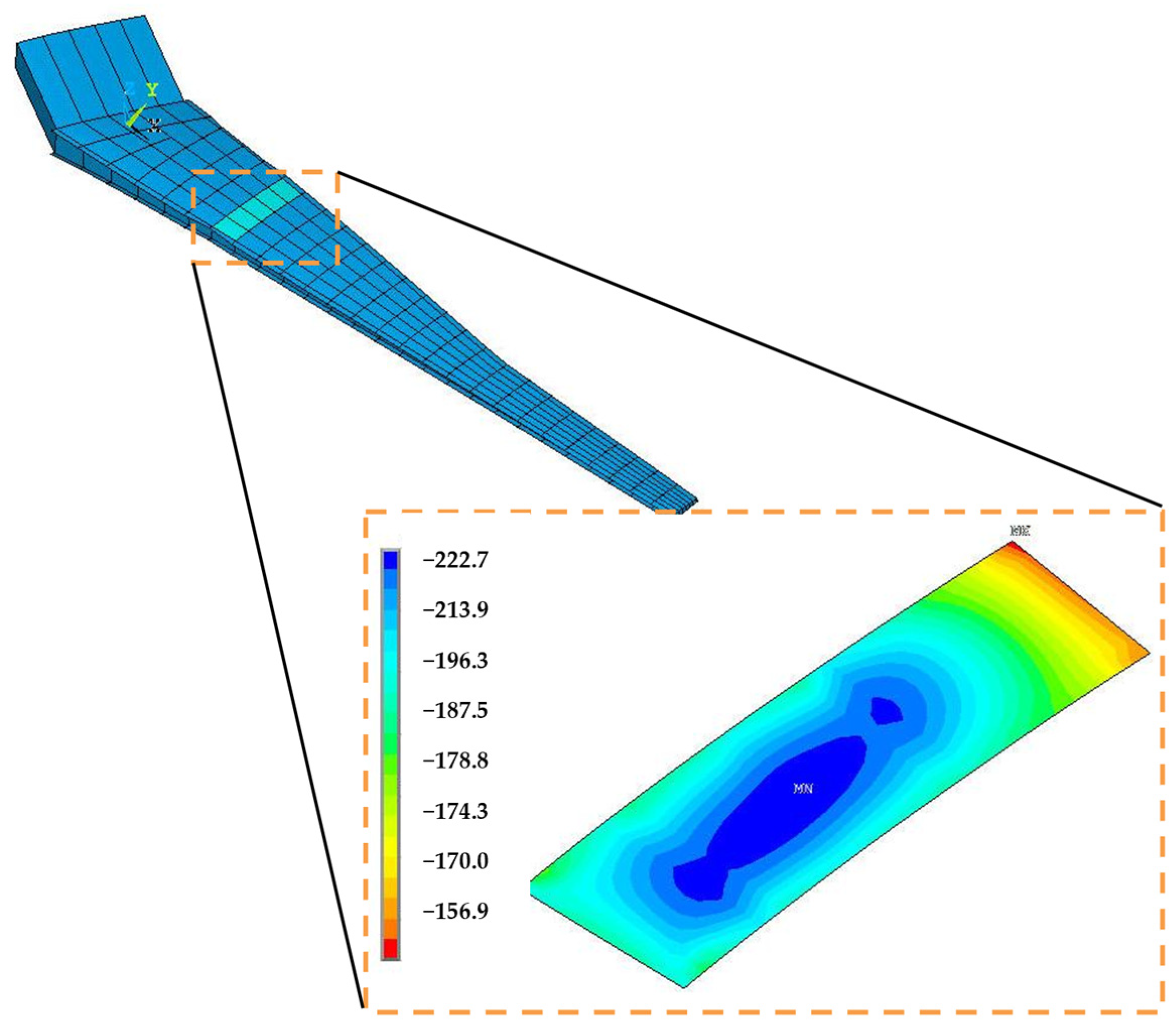
A static solution of the simplified FE model reveals the stress field in the wing structural parts, as well as the load distribution at the boundaries of each stiffened panel. The determination of the applied compressive loads N x of the panels, due to the bending of the wing, is achieved through the post-processing results of the static solution. The compressive load is assumed to be uniformly distributed, taken to be the average value of the normal stress distribution, Figure 10, in each stiffened panel.
The boundary conditions of each stiffened panel are assumed to be simply supported at all edges. Even if those boundary conditions do not accurately represent the attachment of the stiffened panels with the spars and the ribs, these boundary conditions are traditionally selected for preliminary design analyses, due to the conservative results that they provide.

4.3. Buckling Constraint and Optimization Loop

The developed macromodelling approach enables the simplification of the way the stiffeners are taken into account in the analysis, by excluding the explicit stiffener modelling from the model, as their stiffness is appropriately smeared into the panel geometry, as shown in Figure 1, in a way that their effect on buckling response is efficiently considered. For the current application, blade shapes are assumed with a pitch of 60 mm. The ratio of the skin-stiffener cross-sectional area is taken to be 3:1; the selected geometric characteristics are typical for such an aircraft wing size. Consequently, the calculation of the critical buckling load, due to compressive loads, of stiffened composite panels can be performed using un-stiffened panel analytical formulations, Equation (22).
A Reserve Factor (RF) for the critical compressive buckling load can then be determined by Equation (23). Equation (23) is the buckling constraint that ensures the structural stability of stiffened panels of the wing’s upper cover.
R F = N c r N x
In Equation (23), R F is the safety factor for global buckling due to compression, N c r is the critical-allowable buckling load, determined by Equation (22), and N x is the applied load.
In the present optimization procedure, the panel’s thickness recalculation ( t i + 1 ) follows the rule:
t i + 1 = t i 4 R F i 4
Equation (24) arises from Equations (25) and (26), which express the R F s of two subsequent iterations ( i ) and ( i + 1 ). The reserve factor of the i t h iteration is R F i and is calculated as a function of the applied load P i and panel thickness t i .
R F i = N c r i N i = f t i 3 P i
Similarly, the R F of the sequential iteration ( i + 1 ) is given by the first part of Equation (26).
R F i + 1 = N c r i + 1 N i + 1 = f t i + 1 3 P i × t i t i + 1 = f t i + 1 4 P i × t i
Equation (24) yields from the substitution of Equation (25) to Equation (26) and solving with respect to panel thickness t i + 1 .   The iterative procedure is performed until an optimum sizing is achieved, which apparently is achieved when an R F of one or less ( R F f i n a l   1 ) is achieved.
The thicknesses of the homogenized upper cover composite panels of 25 section stations of the lateral wing are determined using the macromodelling approach. Each section station comprises five panels of different thickness.
The sizing procedure of the upper cover is completed after three iterations, beginning with an initial size for the upper cover that has been calculated based on allowable strain constraints only. In the first iteration, an upper cover weight increase is calculated because the buckling criterion is introduced. The number of necessary iterations is determined primarily by the RFs of the panels and, secondly, by the convergence of the upper cover weight. After the second iteration, the RFs for all panels are calculated to be less than one, so panel buckling has prevailed. Simultaneously, the weight of the upper cover converges satisfactorily after the third iteration (0.7% maximum variation of upper cover weight is observed between the two last sequential iterations). Finally, it is worth noting that the proposed approach achieved convergence in approximately 15 min using standard computational resources (Intel Core i7, 16 GB RAM). In contrast, a detailed FE model would require at least two orders of magnitude more computational time for an equivalent buckling analysis. This observation is consistent with findings in the literature, where the cost of detailed FE simulations for stiffened composite structures has been shown to exceed that of analytical or reduced-order models by several orders of magnitude, particularly in iterative optimisation scenarios (e.g., ref. [29]).

5. Conclusions

This paper presents an alternative macromodelling methodology for the buckling analysis of large-scale stiffened composite structures. The analysis utilises energy methods and allows for the calculation of panel stiffness properties by considering the effects of stiffened panel geometric asymmetry and loading system eccentricity. The developed macromodelling approach leverages all available analytical closed-form buckling solutions that are valid for homogeneous unstiffened panels and extends them to anisotropic structures that include stiffened panels, through the introduction of equivalent bending stiffness terms and equivalent loading systems in relevant closed-form buckling formulations. Consequently, this methodology is suitable for the preliminary design optimisation of large-scale lightweight stiffened composite structures (e.g., aircraft wings, fuselages, ship hulls, or other structures), where many optimisation loops are necessary to create panels that meet specified buckling constraints.
Consequently, the proposed methodology offers a practical and scalable alternative to CAD/CAE workflows, especially during the early stages of aircraft structural design. While modern CAD-integrated FE tools enable rapid stress analysis at the component level, they still rely on fully developed geometry and fine mesh discretisation to capture buckling phenomena—requirements that are often unavailable or impractical during conceptual design. In contrast, the developed smearing approach enables the construction of simplified models by homogenizing the stiffeners into the skin, thereby reducing the overall model complexity required for buckling and mass estimations. This dual capability significantly accelerates iterative sizing and mass trade-off studies, which are vital in weight-sensitive applications such as wing design. Moreover, it avoids the time-consuming task of manually modelling numerous stiffeners and allows for the early verification of design directions before committing to high-fidelity modelling.
This method is a complementary tool to CAD/CAE software—providing a lightweight analytical framework that supports early decision making, especially in large-scale structures comprising hundreds of stiffened panels. Even in the detailed design phase, it can serve as an independent verification tool, enhancing confidence in FE results and aligning with best practices in certification-driven industries such as aerospace. Under these conditions, the proposed approach offers clear advantages in both speed and practicality.
To demonstrate the effectiveness of the proposed approach, an extensive parametric study examines the validity of the macromodelling methodology for calculating buckling loads, focusing on simply supported stiffened panels with orthotropic thin skins and stiffeners subject to longitudinal and transverse compression. The validation of the macromodelling approach involves comparing its results to the corresponding reference results obtained from detailed, large-scale numerical models, where the stiffeners are explicitly represented.
In the case of thin stiffened anisotropic structure panels supported by a high number of stiffeners, the buckling results calculated by the developed macromodelling approach align satisfactorily with the reference FE results. In situations where the number of stiffeners decreases, it has been demonstrated that stiffener density significantly influences the reliable prediction of buckling loads when the macromodelling approach is employed. This occurs because, as the number of stiffeners diminishes, local buckling becomes more prevalent than global buckling; consequently, the macromodelling approach yields less accurate results.
Finally, the developed methodology is demonstrated in the sizing optimisation procedure of an Airbus A330 composite wingbox, taking into account the global buckling constraint due to axial compression. A simplified FE model has been developed, and the global buckling criterion is established. An iterative process is applied to resize the thickness of the panels, ensuring each panel is sized for optimal buckling resistance. The wing’s sizing optimisation procedure was proven highly efficient, as it requires minimal computational effort and reasonable solution time, compared to multi-million degrees-of-freedom full wing models with explicitly represented stiffeners.

Author Contributions

Conceptualization, D.G.S. and G.N.L.; Methodology, D.G.S. and G.N.L.; Software, D.G.S.; Validation, D.G.S.; Formal Analysis, D.G.S.; Investigation, D.G.S.; Resources, D.G.S.; Data Curation, D.G.S.; Writing—Original Draft Preparation, D.G.S.; Writing—Review & Editing, D.G.S. and G.N.L.; Visualization, D.G.S.; Supervision, G.N.L.; Project Administration, G.N.L.; Funding Acquisition, G.N.L. All authors have read and agreed to the published version of the manuscript.

Funding

This research was funded by the EU research project “Advanced Low-Cost Aircraft Structure” (ALCAS) grant number 516092.

Data Availability Statement

The raw data supporting the conclusions of this article will be made available by the authors on request.

Acknowledgments

The authors wish to acknowledge AIRBUS-UK for the support of this research.

Conflicts of Interest

The authors declare no conflict of interest.

Appendix A

The final expression of the strain energy of the skin U s k i n as a function of the out-of-plane displacements w s k i n 0 only is available below.
U s k i n = 1 2 0 a 0 b { A 11 A 22 N x A 12 N y A 22 A 11 A 12 2 + A 12 B 12 A 22 A 11 A 12 2 2 w s k i n 0 x 2 A 22 B 12 A 12 B 22 A 22 A 11 A 12 2 2 w s k i n 0 y 2 2 + 2 A 12 [ A 22 N x A 12 N y A 22 A 11 A 12 2 + A 12 B 12 A 22 A 11 A 12 2 2 w s k i n 0 x 2 A 22 B 12 A 12 B 22 A 22 A 11 A 12 2 2 w s k i n 0 y 2 ] [ A 11 N y A 12 N x A 22 A 11 A 12 2 A 11 B 12 A 22 A 11 A 12 2 2 w s k i n 0 x 2 A 11 B 22 A 12 B 12 A 22 A 11 A 12 2 2 w s k i n 0 y 2 ] + A 22 [ A 11 N y A 12 N x A 22 A 11 A 12 2 A 11 B 12 A 22 A 11 A 12 2 2 w s k i n 0 x 2 A 11 B 22 A 12 B 12 A 22 A 11 A 12 2 2 w s k i n 0 y 2 ] 2 + A 66 N x y A 66 B 66 A 66 2 2 w s k i n 0 x y 2 2 B 12 [ ( A 11 N y A 12 N x A 22 A 11 A 12 2 A 11 B 12 A 22 A 11 A 12 2 2 w s k i n 0 x 2 A 11 B 22 A 12 B 12 A 22 A 11 A 12 2 2 w s k i n 0 y 2 ) 2 w s k i n 0 x 2 + ( A 22 N x A 12 N y A 22 A 11 A 12 2 + A 12 B 12 A 22 A 11 A 12 2 2 w s k i n 0 x 2 A 22 B 12 A 12 B 22 A 22 A 11 A 12 2 2 w s k i n 0 y 2 ) 2 w s k i n 0 y 2 ] B 22 [ A 11 N y A 12 N x A 22 A 11 A 12 2 A 11 B 12 A 22 A 11 A 12 2 2 w s k i n 0 x 2 A 11 B 22 A 12 B 12 A 22 A 11 A 12 2 2 w s k i n 0 y 2 ] 2 w s k i n 0 y 2 4 B 66 2 w s k i n 0 x y N x y A 66 B 66 A 66 2 2 w s k i n 0 x y + D 11 2 w s k i n 0 x 2 2 + 2 D 12 2 w s k i n 0 x 2 2 w s k i n 0 y 2 + D 22 2 w s k i n 0 y 2 2 + 4 D 66 2 w s k i n 0 x y 2 } dx dy

Appendix B

Table A1. Comparison of Numerical, Analytical, and Macromodelling Results for 10-Stiffener Configuration.
E I s t i f f e n e r s / E I p l a t e  (%)Numerical Reference (N)(Mittelstedt, [17]) (N)Macrom. Approach (N)%Error w.r.t. Numerical Reference
0.00%248924932497.5−0.34%
0.25%2697.22574.52573.84.57%
2.00%2907.52800.42791.14.00%
6.75%3311.53242.43205.13.21%
16.00%3968.63971.23873.02.41%
31.25%4933.45058.44848.81.71%
54.00%6258.26575.26183.61.19%
85.75%7991.88591.67925.60.83%
95.27%8494.29182.28430.10.76%
Table A2. Comparison of Numerical, Analytical, and Macromodelling Results for Five-Stiffener Configuration.
E I s t i f f e n e r s / E I p l a t e  (%)Numerical Reference (N)(Mittelstedt, [17]) (N)Macrom. Approach (N)%Error w.r.t.
Numerical Reference
0.0%2497.52497.52497.5−0.34%
1.0%2658.82658.32658.83.84%
8.0%3274.93294.63274.90.89%
27.0%4616.64712.34616.6−3.17%
64.0%6943.57220.46943.5−7.02%
91.1%8553.38979.28553.3−8.70%
98.9%9007.39478.09007.3−9.09%
Table A3. Comparison of Numerical, Analytical, and Macromodelling Results for Three-Stiffener Configuration.
E I s t i f f e n e r s / E I p l a t e  (%)Numerical Reference (N)(Mittelstedt, [17]) (N)Macrom. Approach (N)%Error w.r.t. Numerical Reference
0.0%2489.02497.52497.5−0.34%
2.0%2826.72760.6242762.92.26%
16.2%3730.53967.6553959.3−6.13%
54.7%5759.96809.016662.2−15.66%
75.0%6746.08238.4558017.5−18.85%
99.8%7903.09951.4069633.1−21.89%
Table A4. Comparison of Numerical, Analytical, and Macromodelling Results for 10-Stiffener Configuration in compression in the transverse direction.
E I s t i f f e n e r s / E I p l a t e  (%)Numerical Reference (N)Macrom. Approach (N)%Error w.r.t. Numerical Reference
0.0%2464.22470−0.2%
0.3%2704.325505.7%
2.0%2945.227008.3%
6.8%3389.131955.7%
16.0%4102.438905.2%
31.3%4422.841805.5%
54.0%4810.945355.7%
85.8%5313.550105.7%
95.3%5458.851455.7%

References

  1. Peng, L.X.; Liew, M.; Kitipornchai, S. Buckling and free vibration analyses of stiffened plates using FSDT mesh-free method. J. Sound Vib. 2006, 289, 421–449. [Google Scholar] [CrossRef]
  2. Stroud, W.J.; Greene, W.H. Buckling Loads for Stiffened Panels Subjected to Combined Longitudinal Compression and Shear Loadings: Results Obtained with PASCO, EAL and STAGS Computer Programs (NASA TM-83194); NASA Langley Research Center: Hampton, VA, USA, 1981.
  3. Wang, J.T.S.; Hsu, T.M. Discrete analysis of stiffened composite cylindrical shells. AIAA J. 1985, 23, 1753–1761. [Google Scholar] [CrossRef]
  4. Graciano, C.; LagFerqvist, O. Critical buckling of longitudinal stiffened webs subjected to compressive edge loads. J. Constr. Steel Res. 2003, 59, 1119–1146. [Google Scholar] [CrossRef]
  5. Grondin, G.Y.; Chen, Q.; Elwi, A.E.; Cheng, J.J. Stiffened steel plates under compression and bending. J. Constr. Steel Res. 1998, 45, 125–148. [Google Scholar] [CrossRef]
  6. Hosseini-Toudeshky, H.; Ovesy, H.R.; Kharazi, M. The development of an approximate method for the design of bead-stiffened composite panels. Thin-Walled Struct. 2005, 43, 1663–1676. [Google Scholar] [CrossRef]
  7. Moradi, B.; Parsons, I.D. A comparison of techniques for computing the buckling loads of stiffened shells. Comput. Struct. 1993, 46, 505–514. [Google Scholar] [CrossRef]
  8. Mukhopadhyay, M. Finite element buckling analysis of stiffened plates. Comput. Struct. 1990, 34, 795–803. [Google Scholar] [CrossRef]
  9. Rikards, R.; Chate, A.; Ozolinsh, O. Analysis for buckling and vibrations of composite stiffened shells and plates. Compos. Struct. 2001, 51, 361–370. [Google Scholar] [CrossRef]
  10. Toulios, M.; Caridis, P.A. The effect of aspect ratio on the elastoplastic response of stiffened plates loaded in uniaxial edge compression. Comput. Struct. 2002, 80, 1317–1328. [Google Scholar] [CrossRef]
  11. Heder, M. A simple method to estimate the buckling stress of stiffened panels. Compos. Struct. 1993, 26, 95–107. [Google Scholar] [CrossRef]
  12. Kumar, Y.V.S.; Mukhopadhyay, M. A new finite element for buckling analysis of laminated stiffened plates. Compos. Struct. 1999, 46, 321–331. [Google Scholar] [CrossRef]
  13. Grondin, G.Y.; Elwi, A.E.; Cheng, J.J.R. Buckling of stiffened steel plates—A parametric study. J. Constr. Steel Res. 1999, 50, 151–175. [Google Scholar] [CrossRef]
  14. Byklum, E.; Steen, E.; Amdahl, J. A semi-analytical model for global buckling and postbuckling analysis of stiffened panels. Thin-Walled Struct. 2004, 42, 701–717. [Google Scholar] [CrossRef]
  15. Loughlan, J. The buckling performance of composite stiffened panel structures subjected to combined in-plane compression and shear loading. Compos. Struct. 1994, 29, 197–212. [Google Scholar] [CrossRef]
  16. Loughlan, J.; Delaunoy, J.M. The buckling of composite stiffened plates with some emphasis on the effects of fiber orientation and loading configuration. Compos. Struct. 1993, 25, 485–494. [Google Scholar] [CrossRef]
  17. Mittelstedt, C. Closed-form buckling analysis of stiffened composite plates and identification of minimum stiffener requirements. Int. J. Eng. Sci. 2008, 46, 1011–1034. [Google Scholar] [CrossRef]
  18. Timoshenko, S.P.; Gere, J.M. Theory of Elastic Stability; McGraw-Hill Book Company: New York, NY, USA, 1961. [Google Scholar]
  19. Bedair, O.K. A contribution to the stability of stiffened plates under uniform compression. Comput. Struct. 1998, 66, 535–570. [Google Scholar] [CrossRef]
  20. Li, L.; Bettess, P. Buckling of stiffened plates and design of stiffeners. Int. J. Press. Vessel. Pip. 1997, 74, 177–187. [Google Scholar] [CrossRef]
  21. Mittelstedt, C. Closed-form analysis of the buckling loads of uniaxially loaded blade-stringer-stiffened composite plates considering periodic boundary conditions. Thin-Walled Struct. 2007, 45, 371–382. [Google Scholar] [CrossRef]
  22. Mittelstedt, C. Explicit analysis and design equations for buckling loads and minimum stiffener requirements of orthotropic and isotropic plates under compressive load braced by longitudinal stiffeners. Thin-Walled Struct. 2008, 46, 1409–1429. [Google Scholar] [CrossRef]
  23. Bruns-Treml, M. Program AESOP, Stability-Module; Airbus: Toulouse, France, 2001. [Google Scholar]
  24. Herbeck, L.; Wilmes, H. Design rules for a CFRP outer wing. In Proceedings of the 23rd Congress of International Council of the Aeronautical Sciences (Paper ICAS 2002-341), Toronto, ON, Canada, 8–13 September 2002. [Google Scholar]
  25. Schilling, J.C.; Mittelstedt, C. Local buckling analysis of omega-stringer-stiffened composite panels using a new closed-form analytical approximate solution. Thin-Walled Struct. 2020, 147, 106534. [Google Scholar] [CrossRef]
  26. Schilling, J.C.; El Atamann, D.; Voges, J.; Mittelstedt, C. Local buckling of omega-stringer stiffened composite panels under compression–shear interaction. Thin-Walled Struct. 2022, 180, 109838. [Google Scholar] [CrossRef]
  27. Schilling, J.C.; Mittelstedt, C. Shear buckling of omega-stringer-stiffened panels. Int. J. Mech. Sci. 2021, 207, 106646. [Google Scholar] [CrossRef]
  28. Schilling, J.C.; Mittelstedt, C. Approximate computational model for shear-loaded stiffened composite panels. Proc. Appl. Math. Mech. 2021, 21, e202100093. [Google Scholar] [CrossRef]
  29. Bisagni, C.; Vescovini, R. Fast Tool for Buckling Analysis and Optimization of Stiffened Panels. J. Aircr. 2009, 46, 2041–2053. [Google Scholar] [CrossRef]
  30. Bacarreza, O.; Aliabadi, M.H.; Apicella, A. Robust design and optimization of composite stiffened panels in post-buckling. Struct. Multidiscip. Optim. 2014, 50, 829–841. [Google Scholar] [CrossRef]
  31. Jaunky, N.; Knight, N.F.; Ambur, D.R. Formulation of an improved smeared stiffener theory for buckling analysis of grid-stiffened composite panels. Compos. Part B Eng. 1996, 27, 519–526. [Google Scholar] [CrossRef]
  32. Philips, J.L.; Guerdal, Z. Structural Analysis and Optimum Design of Geodesically Stiffened Composite Panels; Virginia Polytechnic Institute and State University, Center for Composite Materials and Structures: Blacksburg, VA, USA, 1990. [Google Scholar]
  33. Reddy, A.D.; Valisetty, R.R.; Rehfield, W. Continuous filament concepts for aircraft fuselage structures. J. Aircr. 1985, 22, 249–255. [Google Scholar] [CrossRef]
  34. Kidane, S.; Li, G.; Helms, J.; Pang, S.S.; Woldesenbet, E. Buckling load analysis of grid stiffened composite cylinders. Compos. Part B Eng. 2003, 34, 1–9. [Google Scholar] [CrossRef]
  35. Xu, Y.; Tong, Y.; Liu, M.; Suman, B. A new effective smeared stiffener method for global buckling of grid-stiffened composite panels. Compos. Struct. 2016, 158, 83–91. [Google Scholar] [CrossRef]
  36. Wang, B.; Tian, K.; Hao, P.; Zheng, Y.; Ma, Y.; Wang, J. Numerical-based smeared stiffener method for global buckling analysis of grid-stiffened composite cylindrical shells. Compos. Struct. 2016, 152, 807–815. [Google Scholar] [CrossRef]
  37. Luan, Y.; Ohlrich, M.; Jacobsen, F. Improvements of the smearing technique for cross-stiffened thin rectangular plates. J. Sound Vib. 2011, 330, 4274–4286. [Google Scholar] [CrossRef]
  38. Hao, P.; Wang, B.; Li, G.; Meng, Z.; Tian, K.; Tang, X. Hybrid optimization of hierarchical stiffened shells based on smeared stiffener method and finite element method. Thin-Walled Struct. 2014, 82, 46–54. [Google Scholar] [CrossRef]
  39. Wang, B.; Tian, K.; Hao, P.; Cai, Y.; Li, Y.; Sun, Y. Hybrid analysis and optimization of hierarchical stiffened plates based on asymptotic homogenization method. Compos. Struct. 2015, 132, 136–147. [Google Scholar] [CrossRef]
  40. Ye, L.; Zhu, S.; Jiang, W.; Xu, Y.; Ke, L. Design and optimization of composite sub-stiffened panels. Compos. Struct. 2020, 240, 112084. [Google Scholar] [CrossRef]
  41. Meng, Z.; Luo, X.; Zhou, H. Lightweight design of arcuately stiffened cylindrical shells based on smeared stiffener method and active learning strategy. Thin-Walled Struct. 2022, 174, 109167. [Google Scholar] [CrossRef]
  42. Zhang, G.; Hu, Y.; Yan, B.; Tong, M.; Wang, F. Buckling and post-buckling analysis of composite stiffened panels: A ten-year review (2014–2023). Thin-Walled Struct. 2024, 205, 112525. [Google Scholar] [CrossRef]
  43. Tsai, S.T.; Hahn, H.T. Introduction to Composite Materials; Technomic Publishing Company, Inc.: Basel, Switzerland, 1980. [Google Scholar]
  44. Ewing, M.S.; Hinger, R.J.; Leissa, A.W. On the validity of the reduced bending stiffness method for laminated composite plate analysis. Compos. Struct. 1988, 9, 301–317. [Google Scholar] [CrossRef]
  45. Narita, Y.; Leissa, A.W. Buckling studies for simply supported symmetrically laminated rectangular plates. Int. J. Mech. Sci. 1990, 32, 909–924. [Google Scholar] [CrossRef]
  46. ANSYS®; Mechanical Release 14.0; ANSYS Inc.: Canonsburg, PA, USA, 2007.
  47. Madier, D. Practical Finite Element Analysis for Mechanical Engineers; FEA Academy: Montreal, QC, Canada, 2020. [Google Scholar]
  48. Stamatelos, D. Analysis and Preliminary Design of Unconventional Aerostructures. Ph.D. Thesis, University of Patras, Patra, Greece, 2010. [Google Scholar]
Figure 1. (a) Stiffened panel, (b) Homogeneous panel.
Aerospace 12 00726 g001
Figure 2. Applied boundary conditions to the FE model.
Aerospace 12 00726 g002
Figure 3. (a) FE model of a blade stiffened panel, (b) Contour plot of the first buckling mode.
Aerospace 12 00726 g003
Figure 4. Critical buckling load of orthotropic panels braced by 10-stiffeners under uniaxial compression versus percentage of stiffener to skin stiffness [17].
Aerospace 12 00726 g004
Figure 5. Critical buckling load of orthotropic panels braced by five stiffeners under uniaxial compression versus percentage of stiffener to skin stiffness [17].
Aerospace 12 00726 g005
Figure 6. Critical buckling load of orthotropic panels braced by three stiffeners under uniaxial compression versus percentage of stiffener to skin stiffness [17].
Aerospace 12 00726 g006
Figure 7. Critical buckling load of orthotropic stiffened panels braced by 10 stiffeners under transverse compression versus stiffener to skin stiffness ratio.
Aerospace 12 00726 g007
Figure 8. Flow chart of the composite wing optimization procedure.
Aerospace 12 00726 g008
Figure 9. (a): Spanwise load distribution from wing root (Rib stations-1) to tip (Rib station-26). (b): Boundary conditions of the FE model of the scaled A330 wing structure.
Aerospace 12 00726 g009
Figure 10. Stress distribution, σx, in an upper cover panel, in MPa.
Aerospace 12 00726 g010
Disclaimer/Publisher’s Note: The statements, opinions and data contained in all publications are solely those of the individual author(s) and contributor(s) and not of MDPI and/or the editor(s). MDPI and/or the editor(s) disclaim responsibility for any injury to people or property resulting from any ideas, methods, instructions or products referred to in the content.