Abstract
In order to improve mathematical model accuracy of electromechanical actuator (EMA) and solve the problems of low-frequency response and large overshoot for nonlinear systems by using traditional proportional integral derivative (PID) algorithm, a fuzzy single neuron (FSN)-PID algorithm is proposed. Firstly, a complete multi-nonlinear dynamic model of EMA is constructed, which introduces internal friction and current limiter of brushless direct current motors (BLDCMs), dead zone backlash of gear trains, and LuGre friction between output shaft and fin. Secondly, a FSN-PID controller is introduced into the automatic position regulator (APR) of EMA control system, where the gain coefficient K of SN algorithm is adjusted by fuzzy control, and the stability of the controller is proved. In addition, simulations are conducted on the response effect of different fin positions under different algorithms for the analysis of the 6° fin position response; it can be concluded that the rise time with FSN-PID algorithm can be reduced by about 4.561% compared to PID, about 1.954% compared to fuzzy (F)-PID, about 0.875% compared to single neuron (SN)-PID, and about 0.380% compared to back propagation (BP)-PID. For the 4°-2 Hz sine position tracking analysis, it can be concluded that the minimum phase error of FSN-PID algorithm is about 0.4705 ms, which is about 74.44% smaller than PID, about 73.43% smaller than F-PID, about 17.24% smaller than SN-PID, and about 10.81% smaller than BP-PID. Finally, wind tunnel experiments investigate the actual high dynamic flight environment and verify the excellent position tracking ability of FSN-PID algorithm.
1. Introduction
Since the 21st century, a guided projectile (GP) launched by conventional artillery platform has come into being, which has become the development trend and concept of modern artillery. As an indispensable key component of GP system, the performance of electromechanical actuator (EMA) directly affects the dynamic quality in GP flight process and its strike accuracy. The devices that generate control force by manipulating fin, wing surfaces, or changing engine thrust vector to control and stabilize GP are collectively referred to as EMA system. With the development of aerospace industries, the requirements for the volume and weight of EMA, especially the power-to-weight ratio, intelligence, efficiency, and automation of the drive systems, are becoming increasingly stringent [1].
Depending on the driving energy source, actuator system can be divided into electropneumatic actuators (EPAs) [2,3] electrohydraulic actuators (EHAs) [4,5] and EMAs [6,7]. With the advancements of rare earth magnetic materials, power electronics, and motor control techniques, EMAs have emerged as viable alternatives to the EPAs and EHAs [8]. Meanwhile, the significant advancement in motor control technology [9,10,11,12] has made the control accuracy of EMA more precise and the response speed faster. Therefore, EMAs are increasingly being used in various automatic control systems such as missiles, projectiles, rockets, unmanned aerial vehicles (UAV), and so on [13,14]. In the mid-20th century, EMA related technology was first applied in aerospace engineering, primarily for driving the control surface of missiles [15]. In the late 1960s and early 1970s, the United States Air Force (USAF) proposed an electrically powered actuation design (EPAD) plan in response to several flight accidents. In the late 1970s, with the introduction of power-by-wire (PBW) and fly-by-wire (FBW) concepts, the research on the application of motor servo technology to the control fin of aircraft began to be carried out, thus opening the prelude to in-depth research on EMA [16].
Accurate modeling of EMA is the basis for analyzing system dynamic characteristics and improving control accuracy. The EMA belongs to a class of complex structure, time-varying, high-order, and multivariable nonlinear servo systems. In conventional modeling approaches, EMA is assumed to behave as a linear spring without damping or delay, and with a constant stiffness [17,18] which not only does not consider the friction effect inside the motor, but also does not involve the influence of various nonlinear factors in mechanical transmission [19]. However, there are many nonlinear factors in EMA system, which make the results calculated under linear assumptions differ from the real phenomenon. To address this issue, many scholars have conducted extensive research and discussion. Yoo et al. [20] proposed a novel robust control method to actively eliminate the limit-cycle oscillations caused by aeroelastic interaction, and applied it to the EMA system of a guided missile. Li et al. [21] proposed a new seamless observer–controller scheme for hydraulic servo system, and the theoretical analysis proved that the proposed control scheme can guarantee a prescribed transient performance and tracking accuracy. Zheng et al. [1] proposed three integrated structural design strategies for the IEMA system, established a specific mathematical and simulation model, and finally developed an IEMA prototype and conducted a series of experiments. Wan et al. [22] took the nonlinear factors of EMA, the impact dynamics of the linkage mechanism, and the rigid flexible coupling characteristics into account, established a co-simulation model of the flap drive system, performed the experiments with different command frequencies and loads, and discussed the influence of nonlinear characteristics. The above papers only focus on a certain nonlinear characteristic and do not consider the comprehensive impact of multiple nonlinear factors on the system. And although the conventional proportional integral derivative (PID) algorithm has the advantages of not relying on mathematical models, simple structure, convenient parameter adjustment, and easy engineering implementation [23,24] it cannot achieve satisfactory tracking performance when facing unexpected working conditions and multiple nonlinear disturbances.
In the past few decades, the classic three closed-loop PID algorithm has been widely used in EMA control system, it is one of the earlier developed control strategies [25] and its essence is “eliminating errors based on errors”, but it has serious shortcomings in solving problems such as high frequency response, low overshoot, and strong coupling in complex nonlinear systems. Based on this, scholars have proposed some artificial intelligence methods for this problem and applied them to various industries. In order to solve the problem of flat top when EMA tracks a small-angle sinusoidal signal, Zhou et al. [26] proposed an improved sliding mode control method based on a new reaching law, which reduced the flat top phenomenon in the steering process of input signal and improved the control performance of EMA system. Wang et al. [27] proposed a finite time command filtering backstepping control method to address the LuGre nonlinear friction problem in dual motor servo control systems, proved the stability of the closed-loop system, and verified the superiority of the control approach through experiments. Zhang et al. [28] proposed a Vit-S2T network and ELM-PID control for pavement-crack tracking, and experimentally demonstrated the superior and robust nature of this approach in pavement-crack tracking. Wang et al. [29] proposed a hybrid sparrow search optimization PID algorithm to address the robotic arm jittering caused by friction between joints and changes in end loads of industrial robots. Results demonstrated that this method effectively suppresses jittering during motion, thereby enhancing system stability and safety. Due to the excellent approximation performance of fuzzy logic system, it has been widely used in nonlinear control systems in recent years, and has outstanding advantages in dealing with complex systems with imprecision and high uncertainty [30]. In addition, as an effective data and function approximation method, neural network algorithms have strong nonlinear fitting ability and can map arbitrary complex nonlinear relationships through adaptive learning [31].
Inspired by the aforementioned discussions, this paper proposes a fuzzy single neuron (FSN)-PID algorithm to address the issues of incomplete modeling of GP-borne EMA system and low control accuracy of traditional PID methods. The main contributions of the paper are as follows:
- (1)
- To improve the dynamic model accuracy of EMA system, the internal Coulomb friction and current limiter nonlinear factors in BLDCM, backlash in gear trains, and LuGre friction between the output shaft and fin are considered, and a complete dynamic model of EMA is constructed by theory deduction and proof.
- (2)
- A FSN-PID controller is proposed, which utilizes the fuzzy control based on Mamdani’s “min-max” method for online tuning of the gain coefficient K of SN neural network, and the stability of the controller is proved, thereby enhancing the rapidity and robustness of the control system.
- (3)
- Simulation experiments are conducted to analyze the response of EMA for different fin positions as well as the tracking performance for various sine positions. Wind tunnel experiments are conducted to investigate the instantaneous action of fin opening and the superiority of FSN-PID algorithm for high-precision tracking of sine position commands.
2. System Description and Preliminaries
EMA is a kind of nonlinear servo system composed of a main controller, an inverter driver, a logic commutation module, a BLDCM, a gear reducer, an output shaft and a control fin. This section mainly starts from three nonlinear aspects: BLDCM, gear backlash, and friction nonlinearity. A dynamic model of EMA system is established and its dynamic characteristics are analyzed in this section, and its topology is shown in Figure 1 below.

Figure 1.
Topology structure of EMA system.
2.1. Dynamic Model of BLDCM
BLDCMs are widely used in aerospace, robotics, electric vehicles, industrial automation, and military fields due to their simple structure, high efficiency, better reliability, low noise, and easy maintenance [32,33]. The A, B, and C three-phase windings of BLDCMs are symmetrical, and the matrix form of its phase voltage equation can be expressed as follows
where UA, UB, and UC are the three-phase voltage, R is the three-phase resistance, iA, iB, and iC are the three-phase current, L is the three-phase winding self-inductance, M is the three-phase winding mutual inductance, eA, eB, and eC are the three-phase back electromotive force (EMF), and d/dt is differential operator.
When the motor is operating, power from the source is absorbed. Most of the power is transferred through the air gap to the rotor by the torque effect, which is called electromagnetic power Pe, which equals the sum of the product of current and back EMF of three phase, that is,
Ignoring the mechanical loss and stray loss, the Pe is totally turned into kinetic energy under ideal conditions, and the electromagnetic torque Te can be expressed as shown below:
where Ω is the mechanical angular velocity of motor. Similarly, Te can also be expressed as
where KT is the motor torque coefficient, and i is the winding phase current in steady state.
The motor motion equation is as follows:
where TL is the load torque, Jm is the motor rotor moment of inertia, and Bm is the viscous friction coefficient.
By performing Laplace transform on Equations (1)–(5) above, the transfer function form of BLDCMs can be obtained, as shown in Equation (6) below:
Taking into account nonlinear links such as internal current limiter and Coulomb friction, its topology is shown in Figure 2, where Ke is the back EMF coefficient, and the main parameters are shown in Table 1 below.
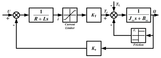
Figure 2.
Nonlinear transfer function structure of BLDCM.

Table 1.
Main parameters of BLDCM.
2.2. Backlash Nonlinearity
Due to its more realistic and concise description of torque transmission between driving and driven components, the dead zone backlash model is used to represent nonlinear transmission links.
The transmission torque τ between driving and driven gears can be expressed as follows:
where k is the stiffness coefficient at the joint of gears, f(z) is the dead zone backlash function, which can be expressed as
where 2α is the backlash width, and the value of α is 0.005 rad, z is the relative angular displacement between driving and driven gears, that is,
where θ1 and θ2 are the angular displacement of driving and driven gears, respectively, and i is the transmission ratio.
Due to the non-differentiable of dead zone function, it is not convenient for controller design, so a continuous approximate dead zone function f*(z) is introduced as
where a > 0 and r > 0 are the undetermined parameters, in order to analyze the degree of approximation to the dead zone function; the difference between them is defined as Δf(z)
Theorem 1.
When parameters a = 1, r = 2/α, the following conclusions can be drawn, (1) . (2) f*(z) is a monotonically increasing function. (3) the area enclosed by f*(z) and Δf(z) is the smallest. (4) .
Proof.
Since Δf(z), f*(z), and f(z) are the odd functions symmetric about origin, so we only need to analyze the part where z ≥ 0. □
- (1)
- When a = 1, .
- (2)
- Differentiating f*(z) yields
- (3)
- Integrating Δf(z) gives the area of the city enclosed by f*(z) and f(z),
It can be concluded that the area S is inversely proportional to the parameter r, and from 0 < rα ≤ 2, it can be inferred that when r = 2/α, the minimum value of the area is . Therefore, when the parameters a = 1 and r = 2/α, the f*(z) is closest to f(z), and the value of r reflects the degree of approximation between the two. It can be seen from Figure 3 below that the degree of approximation gradually deteriorates as r decreases.
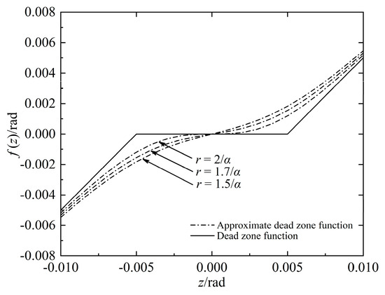
Figure 3.
Dead zone function and approximate dead zone function.
- (4)
- From Equation (10), it can be concluded that Δf(z) is a monotonically increasing function on [0, α] and a monotonically decreasing function on [α, +∞]. So, the maximum value of Δf(z) is , therefore
The transmission torque τ between gears can be rephrased as
2.3. LuGre Friction Nonlinearity
There are friction nonlinear disturbance factors between the output shaft and fin. As an extension of Dahl model, LuGre friction incorporates the deformation of bristles that are unobservable but represent the internal friction state. It considers the average displacement of elastic bristles between contact surfaces to characterize the dynamic characteristics of friction, and more accurately describes the complex static and dynamic characteristics during the friction process [34,35]. The mathematical model of the fin is shown in Figure 4 below.
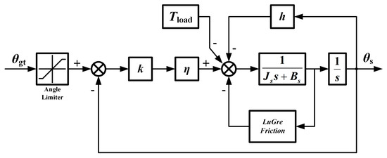
Figure 4.
Topological structure diagram of the fin.
In Figure 4 above, θgt is the deflection angle of gears trains, θs is the deflection angle of control fin, k is the stiffness coefficient, η is the transmission efficiency, Tload is the external uncertain load disturbance, 1/(JsS + Bs) is the mathematical model of fin, and h is the air hinge torque coefficient. Due to the fact that the aerodynamic hinge moment Th on the fin is not only related to the aerodynamic pressure and flight Mach number, but also to the attack angle of GP, the geometric shape, and deflection angle of fin, the variation range is very large. It is generally believed that Th is directly proportional to the deflection angle of the fin, which is an elastic load and can be expressed as follows:
where h = Th max/θs max, Th max is the maximum aerodynamic hinge moment and θs max is the maximum deflection angle.
In addition, LuGre friction nonlinear mathematical model can be expressed as
Equation (17) above represents the dynamic equation for the average deformation of bristles on the contact surface, where ξ is the average deformation of the bristles, ωl is the angular velocity of the fin, and nonlinear function g(ωl) > 0 represents the friction effect. In Equation (18), σ0 is the stiffness coefficient of bristles, FC is the Coulomb friction torque, FS is the maximum static friction torque, vs. is the Stribeck velocity, and e is the exponential term. In Equation (19), Ff is the friction torque, σ1 is the damping coefficient of bristles, and σ2 is the viscous friction coefficient. The specific parameters are shown in Table 2 below.

Table 2.
Main parameters of output shaft.
In summary, this section comprehensively considers the internal nonlinearity of BLDCMs, the dead zone backlash nonlinearity in gear trains, and the LuGre friction nonlinearity between the output shaft and fin, forming a multi-nonlinear mathematical model of EMA system. In addition, there are also other nonlinear factors inside the EMA, such as the position limiter and speed limiter in three closed-loop control systems, the Coulomb friction nonlinear links of each spur gears, and the nonlinear flutter factors carried by the fin itself. However, this paper only considers the influence of main nonlinear factors, and the other nonlinear factors will be further explored in future research.
3. Proposed FSN-PID Method
In this section, we designed a FSN-PID algorithm to improve the position response tracking accuracy of EMA system considering the model multi-nonlinearity and uncertain disturbances. The FSN-PID algorithm is based on the combination of fuzzy control and neural network. It not only leverages the advantages of fuzzy control not relying on the mathematical model of the controlled object and has strong robustness but also inherits the advantages of artificial neural networks that can arbitrarily approximate complex nonlinear functions, simple structure, and algorithm clearly.
3.1. Design of the F-PID Controller
Fuzzy control does not require quantitative mathematical modeling of the controlled process, but attempts to acquire knowledge from experts, that is, expert behavior and experience. Multi-input and multi-output fuzzy controllers usually include five parts: fuzzification, database, rules, inference, and defuzzification. Firstly, the fuzzy controller designed in this paper takes position error e and error change rate ec = de/dt as the inputs of the fuzzy controller, and the weight coefficients ΔKp, ΔKi, and ΔKd as the outputs. The domain range of input and output variables are set to [−6, 6] and the quantization level is 13, that is, [−6, −5, −4, −3, −2, −1, 0, 1, 2, 3, 4, 5, 6]. This variable configuration can enhance computational efficiency without compromising calculation accuracy. Secondly, the database contains various parameters related to fuzzy data processing. The fuzzy subsets of input and output variables are defined as seven fuzzy language values, namely NB (Negative Big), NM (Negative Middle), NS (Negative Small), ZO (Zero), PS (Positive Small), PM (Positive Middle), and PB (Positive Big), respectively. Figure 5 below shows the membership function of the input variable e of F-PID algorithm, which is a “triangle” function, and the other variables are the same.
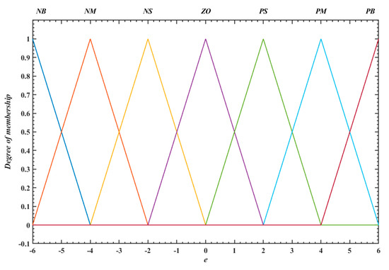
Figure 5.
Membership function of input variable e.
Then, fuzzy rules are established based on control engineering knowledge and experts’ experience, as shown in Table 3 below. For example, when both the e and ec are classified as NB, the system typically exhibits a slower response speed and a large steady-state error. Therefore, assigning the Kp as PB can accelerate the system response, reduce the rise time and steady-state error. However, a shorter rise time may lead to a larger overshoot. Setting the Ki as NB can significantly reduce the overshoot and settling time. Assigning the Kd as PS can slightly reduce the rise time, overshoot, and settling time, thereby enhancing system stability. Similarly, the design logic for the other fuzzy rules can be derived. In addition, Figure 6 shows the fuzzy rules surface.

Table 3.
Fuzzy control rule.

Figure 6.
Fuzzy rules surface diagram of F-PID controller.
Furthermore, fuzzy controllers often use syllogistic deductive reasoning methods. In this section, Mamdani “min-max” method is used to calculate and infer multi-input and multi-output fuzzy relationships, resulting in a total of n (n = 49) inference rules, which are expressed as follows:
| if A1 and B1, then C1; | |
| otherwise, | if A2 and B2, then C2; |
| otherwise, | if A3 and B3, then C3; |
| ⁝ | |
| otherwise, | if Ai and Bi, then Ci; |
| ⁝ | |
| otherwise, | if An and Bn, then Cn; |
| now, | A′ and B′; |
| Conclusion, | then C′. |
Here, Ai (i = 1, 2, 3, …, n) and A′, Bi (i = 1, 2, 3, …, n) and B′, Ci (i = 1, 2, 3, …, n) and C′ are the different fuzzy sets on different fuzzy domains X, Y, and Z, respectively, “otherwise” stands for “or” operation, which can be written in union form during inference calculation, and the total result is
where “and” is the sum operation, “⸰” is the composition operation, “∪” is the maximization operation.
Finally, the centroid method is used for defuzzification to calculate the centroids of a series of points within the output range, which can be expressed as
where {E, EC}ΔK is the output value after defuzzification, and the final output value of F-PID algorithm can be obtained, which can be expressed as
where Kp0, Ki0, and Kd0 are the initial values of weight coefficients Kp, Ki, and Kd in PID algorithm, and Ku1, Ku2, and Ku3 are the output quantization factors, respectively.
3.2. Design of the SN-PID Controller
Single neuron (SN)-PID controller is essentially a variable coefficient, composite, and adaptive artificial neural network that takes the proportional P, integral I, and differential D coefficients of PID algorithm as the input weights of the neurons and simplifies the hidden layer to one. Since the actual engineering process systems are discrete, the discrete incremental PID algorithm is thus often used for control systems, which can be expressed as
The topology of SN-PID algorithm is shown in Figure 7 below:

Figure 7.
The topology of SN-PID algorithm.
The input of state converter reflects the state of the controlled object and control settings in Figure 7, and the output is the state variable required for neuron learning control. The control signal u(k) is generated by neurons through association search and self-learning. The system input r(k) and output y(k), which are the required state quantities x1(k), x2(k), and x3(k) for neuron learning after state transition, is set. K is the proportional gain coefficient, with K > 0. The output u(k) of SN-PID controller can be expressed as
where u(k − 1) is the output value at time k − 1, is the normalized weight coefficient corresponding to xi(k), and the mathematical expression of xi(k) is
Substituting Equation (26) into (25) yields
Comparing Equations (27) and (24), the weight coefficients can be obtained as follows:
Therefore, the SN controller has the characteristics of PID algorithm.
Among them, the calculation method of is
In this section, a supervised Hebb learning rule is used to adjust online; it takes into account the relationship between the weight coefficient and the input, output, and output bias of neurons, which can be expressed as
where ηP, ηI, and ηD are the learning rates of proportional P, integral I, and differential D coefficients, respectively, and z(k) is the performance index, where z(k) = e(k). In addition, selecting a suitable K is particularly important for SN-PID algorithm, in order to achieve online self-tuning of K and improve control quality; this section studies a method to optimize the stability of gain coefficient K by using fuzzy logic.
3.3. Fuzzy Logic Optimization Gain Coefficient K
3.3.1. Controller Topology
This section utilizes the strong robustness of fuzzy logic to perform online self-tuning of the gain coefficient K in SN-PID algorithm, and the topology of FSN-PID controller is shown in Figure 8 below.
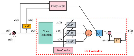
Figure 8.
FSN-PID controller topology structure.
Firstly, the membership functions of input variables e, ec, and output K′ of fuzzy system are set as a combination of “triangular” and “Gauss” types, with the threshold values [−6, 6] and the “Gauss” function employed at the edges. This configuration method aims to enhance the system’s smoothness in handling the edge data, improve overall smoothness, and increase the optimization efficiency of the algorithm. Taking the input e as an example, its membership function is shown in Figure 9, and Figure 10 is the fuzzy rule surface diagram of FSN-PID algorithm. Since the processing flow of ec is identical to that of e, it will not be discussed in detail here. Then, the Mamdani method is also used for fuzzy inference, and defuzzification adopts the centroid method. Finally, the output accurate quantity {E, EC}K′ is obtained, and the final value of gain coefficient K can be expressed as
where K0 is the initial value of K.
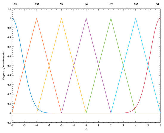
Figure 9.
Input variable e membership function of FSN-PID controller.
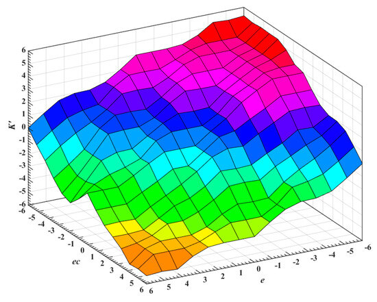
Figure 10.
Fuzzy rules surface diagram of FSN-PID controller.
In summary, this section designs a FSN-PID controller according to the characteristics of multiple nonlinear factors and uncertain external disturbances in the EMA of GP system, which realizes the online self-tuning of K′ and improves the robustness.
3.3.2. Controller Stability Analysis
We define the Lyapunov function V as
where e is the system error, denotes the deviation between gain coefficient K and its desired value K*, and γ is the adaptive coefficient, with γ > 0.
The output of FSN-PID controller is expressed as follows:
whereby defining , Equation (33) can be simplified as
Taking the derivative of system error e yields
where is the desired system output, and is the bounded disturbance.
Taking the derivative of Lyapunov function V yields
and by substituting Equation (36) into Equation (35), the following results can be obtained
Considering the online tuning of gain coefficient K based on fuzzy logic described in Equation (31), it follows that
Substituting Equation (38) into Equation (37) yields
assuming is bounded, i.e., , the derivative of the Lyapunov function satisfies
To enhance the system stability, a negative feedback term is introduced into the controller, and the derivative of error can be modified as
Consequently, the derivative of Lyapunov function can be expressed as
Therefore, when , it follows that . Furthermore, according to LaSalle’s invariance principle, when , the system state , thereby proving the stability of the FSN-PID controller.
3.4. BP-PID Artificial Neural Network
In response to the problems of simple structure and insufficient fitting ability of SN neural network, this section investigates the effects of SN-PID algorithm and multi-layer, multi-neuron neural network algorithms on the control performance of EMA, and introduces a back propagation (BP)-PID neural network algorithm based on back propagation technology [36,37]. This algorithm adopts a three-layer neural network structure of 3 × 8 × 3, consisting of three input layer neurons, eight hidden layer neurons, and three output layer neurons. The structural of this algorithm is shown in Figure 11 below.
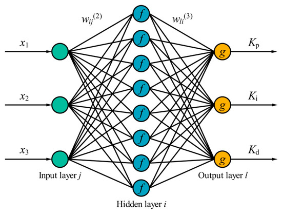
Figure 11.
The structure of BP-PID algorithm.
This algorithm mainly includes two stages, forward propagation of information and backward correction of errors, and the pseudocode of Algorithm 1 is provided below.
| Algorithm 1 Backpropagation neural network |
| begin Forward propagation of information: Input: Output variable of input layer: Input-output variables of hidden layer: Input-output variables of output layer: Performance index function: Back propagation of errors:
end |
4. Simulation Verification
In actual testing process of EMA systems, various indicators and dynamic performance of the system are often evaluated by step or sine position response, where step position reveals the response speed, sine position reveals the tracking accuracy. EMA receives the position command sent by the onboard computer during the flight process of GP. The range of fin deflection angle is often between ±2°~±12°, and frequency is 2~5 Hz.
4.1. Step Position Response Analysis
In this section, the step position response effect of EMA under the setting position of 4°, 6°, 8°, and 10°, respectively, is investigated by combining the actual flight attitude of GP and the motion state of EMA system, and an external sudden disturbance torque of 2 N·m is applied at 0.03 s, as shown in Figure 12 below. Firstly, this section compares the fin position response capability of APR using PID, F-PID, SN-PID, BP-PID, and FSN-PID algorithm for EMA system, respectively, and analyzes the time-domain response performance under 6° position. The specific values are given in Table 4 below.
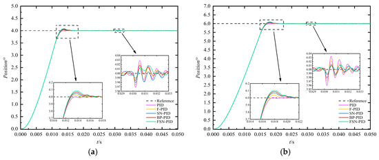
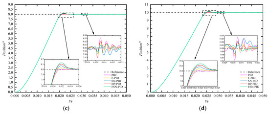
Figure 12.
Response curve of different algorithm for different fin position. (a) 4°; (b) 6°; (c) 8°; (d) 10°.

Table 4.
Different algorithm response indexes under 6° fin response.
It can be concluded from Table 4 and Figure 12b that the FSN-PID algorithm has a shorter rise time tr, about 16.761 ms, which can be reduced by about 4.561% compared to PID, about 1.954% compared to F-PID, about 0.875% compared to SN-PID, and about 0.380% compared to BP-PID, but the peak time tp and overshoot σ are relatively large. The steady-state error of F-PID algorithm is the smallest, which is about 0.00044°. Furthermore, compared to the SN-PID algorithm, the BP-PID algorithm exhibits a shorter tr and smaller steady-state error, which demonstrates the superiority of multi-layer, multi-neuron network structure. Moreover, as shown in Figure 12, under the sudden load disturbance applied at 0.03 s, the FSN-PID controller exhibits faster response speed, smaller steady-state error, and stronger disturbance rejection capability and robustness compared to the other algorithms. In summary, the FSN-PID algorithm has a shorter response time and greater robustness, while the F-PID algorithm has a smaller overshoot and steady-state error, but a relatively longer rise time.
Moreover, this section takes the reference position of 6° as an example to analyze and compare the dynamic characteristics of BLDCM during the motion of EMA under different controllers, including speed, electromagnetic torque, three-phase current, and back EMF. It can be concluded from Figure 13, Figure 14 and Figure 15 that when the motor starts moving with EMA, the instantaneous speed and back EMF are both zero, and the armature current at this time can be expressed as
where Ud is the bus voltage, and ΔU is the voltage drop of the power switches of the bridge inverter; since the voltage drop of the power switches and the armature winding resistance are small, the starting current may reach several times or more than ten times the normal operating current, resulting in the electromagnetic torque being much larger than load torque. When the starting current is large, the speed increases rapidly, leading to an increase in back EMF. In addition, the growth of three-phase current slows down until it reaches a maximum value and then begins to decrease. The decrease in current leads to a decrease in electromagnetic torque, and the acceleration of fin deflection position of EMA increase also decreases accordingly. As the fin position gradually reaches the reference, motor speed rapidly decreases, causing a sudden change in three-phase current, back EMF, and electromagnetic torque. Finally, when the fin position stabilizes at reference, the servo motor stops moving and the entire electromechanical system maintains steady-state operation.
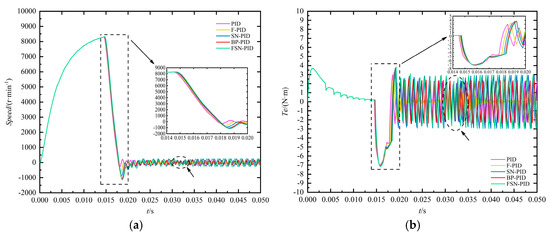
Figure 13.
Motor speed and electromagnetic torque curve. (a) Motor speed; (b) electromagnetic torque.

Figure 14.
Three-phase current curve. (a) I_a; (b) I_b; (c) I_c.

Figure 15.
Three-phase back EMF curve. (a) Back EMF_a; (b) back EMF_b; (c) back EMF_c.
In addition, similar to the response of fin position, the variation patterns of EMA and its various electrical characteristics under different algorithms can be obtained from Figure 13, Figure 14 and Figure 15. Among them, the FSN-PID algorithm has a faster response speed and a more stable electrical mutation trend, while the F-PID algorithm has a smaller steady-state error. The BP-PID algorithm has a faster response speed than the SN-PID algorithm. Although SN-PID algorithm has a shorter response time than F-PID algorithm, the steady-state error is larger.
4.2. Sine Position Response Analysis
During the actual flight process of GP, the onboard computer calculates its flight attitude in real time and sends commands to EMA system, and the fin position moves in a sine signal with the same frequency as the rolling of GP. Therefore, this section simulates the tracking effect of EMA system using different algorithms for sine position under the condition of fin position motion frequency of 2 Hz, amplitude of 4°, 6°, 8°, and 10°, as shown in Figure 16. It also can be concluded that the FSN-PID algorithm has a faster response speed, similar to step position response.
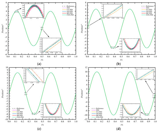
Figure 16.
Sine position tracking curve of EMA under different algorithm. (a) 4°-2 Hz; (b) 6°-2 Hz; (c) 8°-2 Hz; (d) 10°-2 Hz.
Table 5 below compares and analyzes the amplitude and phase error of EMA using different algorithms to track different sine positions. It can be concluded that the FSN-PID algorithm has a smaller phase error; taking the sine position 4°-2 Hz as an example, its minimum phase error is about 0.4705 ms, which is about 74.44% smaller than PID algorithm, about 73.43% smaller than the F-PID algorithm, about 17.24% smaller than the SN-PID algorithm, and about 10.81% smaller than the BP-PID algorithm. Therefore, the FSN-PID algorithm is closer to the reference position.

Table 5.
Sine position response indicators under different algorithms.
Similarly to the step position response, the fin position oscillation controlled by F-PID algorithm is smaller, with a more stable motion state and smaller amplitude error compared to other algorithms. Taking the sine position of 4°-2 Hz as an example, its minimum amplitude error is 0.0018°, which is about 71.88% less than PID algorithm, about 61.70% less than SN-PID algorithm, about 58.14% less than BP-PID algorithm, and about 55.00% less than FSN-PID algorithm. However, the F-PID algorithm has a larger phase error and is not suitable for tracking position signals quickly.
In summary, although the F-PID algorithm has relatively stable position response dynamic characteristics, its phase error is large and cannot be suitable for high-precision tracking of position command issued by onboard computers. SN-PID algorithm has a faster response speed compared to the F-PID algorithm, but the fin position oscillation is larger. The BP-PID algorithm has a stronger fitting ability compared to the SN-PID algorithm due to it having more neurons and more complex network structure. Its amplitude and phase error are significantly reduced compared to the SN-PID algorithm, demonstrating the superiority of multi-layer and multi-neuron network. Finally, the FSN-PID algorithm combines the advantages of fuzzy control and artificial neural network with faster response speed and a closer distance to the reference position.
5. Wind Tunnel Experiments
In general, wind tunnel experiments are primarily employed to investigate aerodynamic characteristics [38]. In this section, a wind tunnel experiment was conducted to simulate the high-dynamic flight environment of GP, analyzing its aerodynamic characteristics and the real-time tracking accuracy of EMA system utilizing the FSN-PID controller. Figure 17 below shows the schematic diagram of fin opening instantaneous action as the initial zero time (t = 0 ms). At this time, the onboard computer sends a fin extension command to EMA, outputs a large current to ignite the gunpowder and produces a large amount of gas, causing the pressure in the chamber to rapidly increase, pull off the locking screw, and the piston moves forward under the pressure. Finally, the spring pushes fin to unlock, and the EMA system is ready to work.
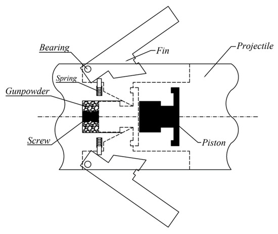
Figure 17.
Schematic diagram of fin opening instantaneous action.
Figure 18 shows the moment when piston collides with the fin, and the fin is regarded as a rigid body with a symmetrical plane and rotates around the bearing O. The mass center of the fin is located at point C, the distance between the straight lines OC is b, and the angle between OC and the width direction of fin is β. Assuming a point-line collision occurs between the piston and fin, with the collision point is F, the collision surface is EG, and the angle between EG and Oy axis direction is θ, the impact of the piston on the fin is S, and the Impact component of S perpendicular to surface EG is S′. An extension line along the direction of S′ intersects with the Oy axis at point D, and the distance between OD is a.
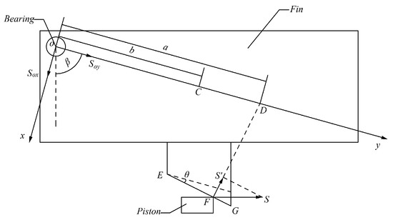
Figure 18.
Moment when piston collides with the fin.
When the impact component S′ given by the piston acts on the impact center of the fin and is perpendicular to the Oy axis, that is, θ = 0, it satisfies
where Cω is the moment of inertia around bearing O, and M is the mass of the fin. Under ideal conditions, bearing O will not be affected by collision impulse, reducing the strength requirements at bearing O. Figure 19 below shows the instantaneous action of fin opening captured by a high-speed camera. It can be clearly seen from the figure that the fin using this structure can be ejected from the fairing effectively and smoothly and can better resist the impact of high dynamic and complex environments.
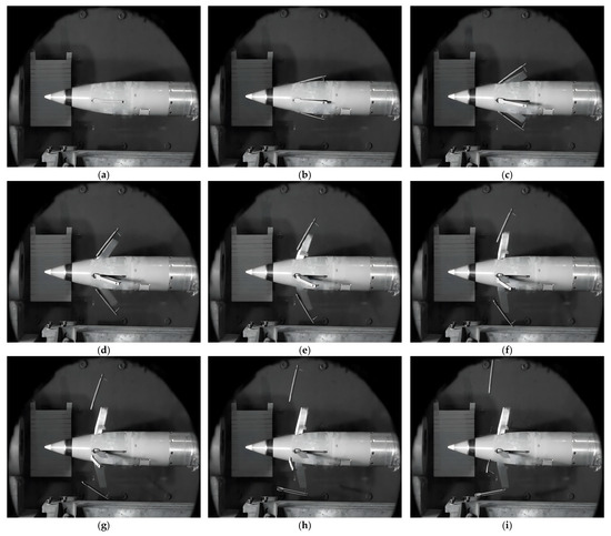
Figure 19.
Instantaneous action of fin opening. (a) 0 ms; (b) 2 ms; (c) 4 ms; (d) 6 ms; (e) 8 ms; (f) 10 ms; (g) 12 ms; (h) 14 ms; (i) 16 ms.
The experiment sets that after 15 s of fin opening, the GP rolls at a speed of 3 r/s. Then, the onboard computer sends position command to the EMA, the fin moves in a sine position with an amplitude of 15° and frequency of 3 Hz, and the motion frequency of fin position is the same as the rolling of GP. Therefore, EMA generates control force to overcome the aerodynamic hinge torque, causing the projectile to receive a resultant force of the vector in upward direction. It can be seen from Figure 20 that relative to the initial horizontal position of the GP, under the condition of incoming wind speed of 1.5 Ma, the GP has clearly obtained a lift provided by EMA, as shown by the red solid line in the figure, where a significant “head up” phenomenon occurs.
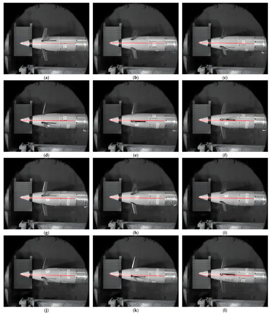
Figure 20.
Experimental diagram of projectile rolling with sine fin position. (a) 15,000 ms; (b) 15,012 ms; (c) 15,024 ms; (d) 15,036 ms; (e) 15,048 ms; (f) 15,060 ms; (g) 15,072 ms; (h) 15,084 ms; (i) 15,096 ms; (j) 15,108 ms; (k) 15,120 ms; (l) 15,132 ms.
Figure 21a below is the fin position curve of the EMA corresponding to Figure 20 using the FSN-PID algorithm. It can be concluded from Figure 21a that in order to obtain a better aerodynamic torque for GP, the fin position amplitude of the 1# and 2# EMAs are the same, but with a 90° phase difference. In Figure 21b, the fin position curves of 1# and 2# EMAs are integrated into the same coordinate system, and the tracking effect within one cycle is analyzed specifically.
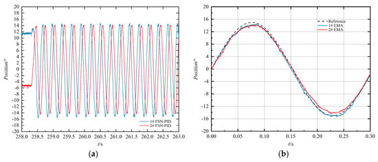
Figure 21.
Fin position under FSN-PID algorithm. (a) position curves of 1# and 2# EMAs; (b) position curves of 1# and 2# EMAs integrated in the same coordinate axis.
Table 6 above presents a comparative analysis of the amplitude and phase errors of the 1# and 2# EMA under the FSN-PID algorithm at a wind speed of 1.5 Ma. It can be concluded that the amplitude error of the 1# EMA is approximately 0.554°, while that of the 2# is approximately 0.602°. The phase error of the 1# EMA is about 0.002 s, that of the 2# is about 0.0015 s. The amplitude and phase errors are relatively close, demonstrating the consistency of the two EMA control systems, which enables the GP to achieve superior flight performance and strike capability.

Table 6.
Position tracking index of 1# and 2# EMA in wind tunnel experiment.
In summary, this section simulates the actual flight environment of GP through wind tunnel experiments, studies the sine position tracking effect of APR using the FSN-PID algorithm, and finally verifies the dynamic frequency response characteristics of EMA system in complex and high dynamic environments.
6. Conclusions
This paper discusses the multi-nonlinear dynamic modeling and high-precision tracking control problem of GP borne EMA and proposes an FSN-PID algorithm. The main contributions are as follows:
- (1)
- In the modeling process of EMA, a multi-nonlinear dynamic model of EMA is built by considering the internal nonlinearity of BLDCM, dead zone backlash of gear trains, and LuGre friction nonlinearity between output shaft and fin.
- (2)
- A FSN-PID controller is proposed and applied to the APR of EMA system by comparing and analyzing the response tracking effect of different step and sine positions, as well as the electrical characteristics of BLDCM, such that the stability of this controller is proved and the control performance superiority is verified through simulation.
- (3)
- The high dynamic flight environment of GP is simulated through wind tunnel experiments, the mechanical structural characteristics of EMA during fin opening are investigated, and the motion performance of EMA under FSN-PID algorithm is analyzed, which further verified the responsiveness and stability of the proposed controller.
Author Contributions
Conceptualization, H.Y., J.G., and W.Y.; methodology, H.Y. and W.Y.; software, H.Y., J.G., and G.J.; validation, J.G., Y.Z., and W.Y.; formal analysis, J.G., G.J., and J.J.; investigation, Y.Z. and W.Y.; resources, J.G., G.J., and W.Y.; data curation, H.Y., J.G., and Y.Z.; writing—original draft preparation, H.Y., J.G., G.J., and W.Y.; writing—review and editing, Y.Z. and J.J.; visualization, G.J., Y.Z., and J.J.; supervision, J.G., W.Y., and J.J.; project administration, H.Y., J.G., and W.Y.; funding acquisition, J.G. and W.Y. All authors have read and agreed to the published version of the manuscript.
Funding
This work was supported in part by the Doctoral Research Initiation Fund of Jiangsu University of Science and Technology under Grant 1032932301; in part by the National Natural Science Foundation of China under Grant 62203191; in part by the National Defense Science and Technology Key Laboratory Fund under Grant 2022JCJQLB06105; in part by the Basic Science (Natural Science) Research Projects in Higher Education Institutions, Jiangsu, under Grant 22KJB590001; and in part by the Foundation Strengthening Program Technology Field Fund under Grant 2023JCJQJJ0357.
Data Availability Statement
Data will be made available on request.
Conflicts of Interest
Author Guilin Jiang was employed by the company Huaihai Industries Group Corporation Limited, China North Industries Group Corporation Limited. The remaining authors declare that the research was conducted in the absence of any commercial or financial relationships that could be construed as a potential conflict of interest.
References
- Zheng, S.; Fu, Y.; Wang, D.; Zhang, W.; Pan, J. Investigations on System Integration Method and Dynamic Performance of Electromechanical Actuator. Sci. Prog. 2020, 103, 0036850420940923. [Google Scholar] [CrossRef] [PubMed]
- Wang, J.; Xu, B.; Lai, J.; Wang, X.; Lu, Y.; Hu, C.; Li, H.; Song, A. Model-Based Linear Control of Nonlinear Pneumatic Soft Bending Actuators. Smart Mater. Struct. 2024, 33, 045022. [Google Scholar] [CrossRef]
- Yang, X.; Zhang, N.; Huang, X.; Bian, R.; Feng, M.; Zhu, X.; Gu, G. Multidirectional Bending Soft Pneumatic Actuator With Fishbone-Like Strain-Limiting Layer for Dexterous Manipulation. IEEE Robot. Autom. Lett. 2024, 9, 3815–3822. [Google Scholar] [CrossRef]
- Niu, S.; Wang, J.; Zhao, J.; Shen, W. Neural Network-Based Finite-Time Command-Filtered Adaptive Backstepping Control of Electro-Hydraulic Servo System with a Three-Stage Valve. ISA Trans. 2024, 144, 419–435. [Google Scholar] [CrossRef]
- Huang, J.; Song, Z.; Wu, J.; Guo, H.; Qiu, C.; Tan, Q. Parameter Adaptive Sliding Mode Force Control for Aerospace Electro-Hydraulic Load Simulator. Aerospace 2023, 10, 160. [Google Scholar] [CrossRef]
- Zhang, M.; Zhou, M.; Liu, H.; Zhang, B.; Zhang, Y.; Chu, H. Friction Compensation and Observer-Based Adaptive Sliding Mode Control of Electromechanical Actuator. Adv. Mech. Eng. 2018, 10, 1687814018813793. [Google Scholar] [CrossRef]
- Kebairi, A.; Becherif, M.; El Bagdouri, M. Modelling, Simulation and Identification of an Engine Air Path Electromechanical Actuator. Control Eng. Pract. 2015, 34, 88–97. [Google Scholar] [CrossRef]
- Kim, S.H.; Tahk, M.-J. Modeling and Experimental Study on the Dynamic Stiffness of an Electromechanical Actuator. J. Spacecr. Rocket. 2016, 53, 708–719. [Google Scholar] [CrossRef]
- Luo, C.; Wang, J.; Miao, Q. Transient Current Ratio Dendrite Net for High-Resistance Connection Diagnosis in BLDCM. IEEE Trans. Power Electron. 2024, 39, 4746–4757. [Google Scholar] [CrossRef]
- Ok, S.; Xu, Z.; Lee, D.-H. A Sensorless Speed Control of High-Speed BLDC Motor Using Variable Slope SMO. IEEE Trans. Ind. Appl. 2024, 60, 3221–3228. [Google Scholar] [CrossRef]
- Zhao, M.; Cao, Y.; Li, C.; Wang, Z.; Shi, T.; Xia, C. Expanded Limit Boundary Explicit Model Predictive Direct Speed Control for PMSMs. IEEE Trans. Power Electron. 2024, 39, 6089–6101. [Google Scholar] [CrossRef]
- Zhang, H.; Deng, L.; Jin, H.; Li, H.; Zheng, S.; Zhou, X. Phase Synchronization-Based Commutation Error Correction Method for Position Sensorless Brushless DC Motor. IEEE Trans. Ind. Inf. 2024, 20, 3964–3973. [Google Scholar] [CrossRef]
- Jang, D.; Shin, H.; Paul, S.; Chang, J.; Yun, Y. Design of a High-Force Electromechanical Actuator for Electrically Driven Lathe Machine. IEEE Trans. Ind. Electron. 2020, 67, 9526–9535. [Google Scholar] [CrossRef]
- Annaz, F.Y.; Kaluarachchi, M.M. Progress in Redundant Electromechanical Actuators for Aerospace Applications. Aerospace 2023, 10, 787. [Google Scholar] [CrossRef]
- Cowan, J.R.; Weir, R.A. Design and Test of Electromechanical Actuators for Thrust Vector Control. In Proceedings of the 27th Aerospace Mechanism Symposium, Moffett Field, CA, USA, 29 September–1 October 1993; pp. 349–366. [Google Scholar] [CrossRef]
- Jensen, S.C.; Jenney, G.D.; Dawson, D. Flight Test Experience with an Electromechanical Actuator on the F-18 Systems Research Aircraft. In Proceedings of the 19th DASC. 19th Digital Avionics Systems Conference, Philadelphia, PA, USA, 7–13 October 2000; Proceedings (Cat. No.00CH37126). IEEE: Philadelphia, PA, USA, 2000; Volume 1, p. 2E3/1-2E310. [Google Scholar]
- Karpel, M. Design for Active and Passive Flutter Suppression and Gust Alleviation. Ph.D. Thesis, Stanford University, Palo Alto, CA, USA, 1981. [Google Scholar]
- Zhang, X.T.; Wu, Z.G.; Yang, C. New Flutter-Suppression Method for a Missile Fin with an Actuator. J. Aircr. 2013, 50, 989–994. [Google Scholar] [CrossRef]
- Gollapudi, A.M.; Velagapudi, V.; Korla, S. Modeling and Simulation of a High-Redundancy Direct-Driven Linear Electromechanical Actuator for Fault-Tolerance under Various Fault Conditions. Eng. Sci. Technol. Int. J. 2020, 23, 1171–1181. [Google Scholar] [CrossRef]
- Yoo, C.-H. Active Control of Aeroelastic Vibrations for Electromechanical Missile Fin Actuation Systems. J. Guid. Control. Dyn. 2017, 40, 3299–3306. [Google Scholar] [CrossRef]
- Li, X.; Chen, X.; Zhou, C. Combined Observer-Controller Synthesis for Electro-Hydraulic Servo System with Modeling Uncertainties and Partial State Feedback. J. Frankl. Inst. 2018, 355, 5893–5911. [Google Scholar] [CrossRef]
- Wan, Q.; Song, C.; Zhou, Y.; Tong, R.; Ma, S.; Liu, G. Modeling and Analysis of the Flap Actuation System Considering the Nonlinear Factors of EMA, Joint Clearance and Flexibility. Aerospace 2024, 11, 440. [Google Scholar] [CrossRef]
- Kjaer, P.C.; Gribble, J.J.; Miller, T.J.E. Dynamic Testing of Switched Reluctance Motors for High-Bandwidth Actuator Applications. IEEE/ASME Trans. Mechatron. 1997, 2, 123–135. [Google Scholar] [CrossRef]
- Mademlis, C.; Kioskeridis, I. Gain-Scheduling Regulator for High-Performance Position Control of Switched Reluctance Motor Drives. IEEE Trans. Ind. Electron. 2010, 57, 2922–2931. [Google Scholar] [CrossRef]
- Bennett, S. Development of the PID Controller. IEEE Control Syst. 1993, 13, 58–62. [Google Scholar] [CrossRef]
- Zhou, M.; Mao, D.; Zhang, M.; Guo, L.; Gong, M. A Hybrid Control with PID–Improved Sliding Mode for Flat-Top of Missile Electromechanical Actuator Systems. Sensors 2018, 18, 4449. [Google Scholar] [CrossRef] [PubMed]
- Wang, B.; Iwasaki, M.; Yu, J. Finite-Time Command-Filtered Backstepping Control for Dual-Motor Servo Systems With LuGre Friction. IEEE Trans. Ind. Inf. 2023, 19, 6376–6386. [Google Scholar] [CrossRef]
- Zhang, J.; Yang, X.; Wang, W.; Brilakis, I.; Davletshina, D.; Wang, H. Robust ELM-PID Tracing Control on Autonomous Mobile Robot via Transformer-Based Pavement Crack Segmentation. Measurement 2025, 242, 116045. [Google Scholar] [CrossRef]
- Wang, P.; Feng, T.; Song, C.; Li, J.; Yang, S.X. A Study of the Stability of an Industrial Robot Servo System: PID Control Based on a Hybrid Sparrow Optimization Algorithm. Actuators 2025, 14, 49. [Google Scholar] [CrossRef]
- Yang, C.; Chen, R.; Wang, W.; Li, Y.; Shen, X.; Xiang, C. Cyber-Physical Optimization-Based Fuzzy Control Strategy for Plug-in Hybrid Electric Buses Using Iterative Modified Particle Swarm Optimization. IEEE Trans. Intell. Veh. 2023, 8, 3285–3298. [Google Scholar] [CrossRef]
- Lu, Y.; Li, T.; Deng, Y. Predication of Water Pollution Peak Concentrations by Hybrid BP Artificial Neural Network Coupled with Genetic Algorithm. Appl. Artif. Intell. 2024, 38, 2341356. [Google Scholar] [CrossRef]
- Zhang, H.; Wu, H.; Jin, H.; Li, H. High-Dynamic and Low-Cost Sensorless Control Method of High-Speed Brushless DC Motor. IEEE Trans. Ind. Inf. 2023, 19, 5576–5584. [Google Scholar] [CrossRef]
- Gamazo-Real, J.-C.; Martínez-Martínez, V.; Gomez-Gil, J. ANN-Based Position and Speed Sensorless Estimation for BLDC Motors. Measurement 2022, 188, 110602. [Google Scholar] [CrossRef]
- Colantonio, L.; Dehombreux, P.; Hajžman, M.; Verlinden, O. 3D Projection of the LuGre Friction Model Adapted to Varying Normal Forces. Multibody Syst. Dyn. 2022, 55, 267–291. [Google Scholar] [CrossRef]
- Dai, K.; Zhu, Z.; Shen, G.; Tang, Y.; Li, X.; Wang, W.; Wang, Q. Adaptive Force Tracking Control of Electrohydraulic Systems with Low Load Using the Modified LuGre Friction Model. Control Eng. Pract. 2022, 125, 105213. [Google Scholar] [CrossRef]
- Wu, W.; Yao, B.; Huang, J.; Sun, S.; Zhang, F.; He, Z.; Tang, T.; Gao, R. Optimal Temperature and Humidity Control for Autonomous Control System Based on PSO-BP Neural Networks. IET Control Theory Appl. 2023, 17, 2097–2109. [Google Scholar] [CrossRef]
- Wang, B.; Jiang, Z.; Hu, P.-D. Study on 6-DOF Active Vibration-isolation System of the Ultra-precision Turning Lathe Based on GA-BP-PID Control for Dynamic Loads. Adv. Manuf. 2024, 12, 33–60. [Google Scholar] [CrossRef]
- Ouyang, D.; Yang, W.; Deng, E.; Wang, Y.; He, X.; Tang, L. Comparison of Aerodynamic Performance of Moving Train Model at Bridge–Tunnel Section in Wind Tunnel with or without Tunnel Portal. Tunn. Undergr. Space Technol. 2023, 135, 105030. [Google Scholar] [CrossRef]
Disclaimer/Publisher’s Note: The statements, opinions and data contained in all publications are solely those of the individual author(s) and contributor(s) and not of MDPI and/or the editor(s). MDPI and/or the editor(s) disclaim responsibility for any injury to people or property resulting from any ideas, methods, instructions or products referred to in the content. |
© 2025 by the authors. Licensee MDPI, Basel, Switzerland. This article is an open access article distributed under the terms and conditions of the Creative Commons Attribution (CC BY) license (https://creativecommons.org/licenses/by/4.0/).