Article

Guidance and Control Architecture for Rendezvous and Approach to a Non-Cooperative Tumbling Target

Department of Industrial Engineering, University of Naples “Federico II”, Piazzale Vincenzo Tecchio, 80, 80125 Napoli, Italy
*
Author to whom correspondence should be addressed.
Aerospace 2025, 12(8), 708; https://doi.org/10.3390/aerospace12080708
Submission received: 16 July 2025 / Revised: 5 August 2025 / Accepted: 6 August 2025 / Published: 10 August 2025

Abstract

This paper proposes a novel Guidance and Control architecture for close-range rendezvous and final approach of a chaser spacecraft towards a non-cooperative and tumbling space target. In both phases, reference trajectory generation relies on a Sequential Convex Programming algorithm which iteratively solves a non-linear optimization problem accounting for propellant consumption, relative dynamics, collision avoidance and navigation sensor pointing constraints. At close range, trajectory tracking is entrusted to a translational H-infinity controller, coupled with a quaternion-feed-back regulator for target pointing. In the final approach phase, an attitude-pointing strategy is adopted, requiring a six degree-of-freedom H-infinity controller to follow a reference roto-translational trajectory generated to ensure target-chaser motion synchronization. Performance is evaluated in a high-fidelity simulation environment that includes environmental perturbations, navigation errors, and actuator (i.e., cold gas thrusters and reaction wheels) modelling. In particular, the latter aspects are also addressed by integrating the proposed solution within a complete Guidance, Navigation and Control pipeline including a state-of-the-art LIDAR-based relative navigation filter and a dispatching function for the distribution of commanded control actions to the actuation system. A statistical analysis on 1000 simulations shows the robustness of the proposed approach, achieving centimeter-level position accuracy and sub-degree attitude accuracy near the docking/berthing point.

1. Introduction

The significant interest of the space community in In-Orbit Servicing (IOS) and Active Debris Removal (ADR) operations has driven the need for the development of advanced techniques for autonomous Rendezvous and Proximity Operations (RPOs) with non-cooperative target spacecraft [1]. These activities are essential for mitigating the risks associated with the growing accumulation of orbital debris [2]. One of the major challenges to be addressed is the design of an autonomous Guidance, Navigation and Control (GNC) system to overcome the limitations imposed by ground communication delays, particularly during the final approach phases [3].
Additional challenges arise from the need to account for a coupled relative orbit and attitude dynamics in the formulation of the guidance and control problems as the relative distance reduces to few meters. Indeed, a proper synchronization strategy is required to satisfy terminal constraints, like those on the maximum allowable relative translational and angular rates between the servicer and the target docking/berthing interfaces [4].
However, to the best of authors’ knowledge, few works in the literature address the Guidance and Control problem (G&C) considering the coupled effects between the rotational and translational dynamics at design level.
Concerning the guidance task, many studies simplify the problem, by treating the spacecraft as point masses, thus only addressing the translational motion [5,6,7]. This solution is valid as long as the target is collaborative, i.e., it keeps a fixed attitude to ease the docking operations. If the target is tumbling, the above-mentioned synchronization constraints introduce non-negligible dynamic coupling between translational and rotational motion [8]. In this context, an analytical method, which provides a roto-translational reference trajectory, is formulated in [9]; specifically, a multi-step maneuver-based guidance strategy is implemented assuming continuous thrust capabilities, but without accounting for propellant consumption optimization. Another analytical method for reference trajectory generation in the considered scenario is described in [10]. Within this approach, the chaser’s nominal translational trajectory is constrained to lie along a specified direction, namely the approach axis expressed in a target-fixed body frame, while the relative velocity decays exponentially over time; the attitude problem is instead addressed assuming that, at the start of the scenario, the servicer is already aligned with the approach corridor, so that the chaser has to track the tumbling motion of the target by maintaining a constant relative orientation. However, the work in [10] does not account for collision avoidance and target visibility constraints.
While analytical methods allow limiting the computational cost, they provide suboptimal solutions in terms of propellant consumption, flight duration, or a combination of both. For this reason, optimization-based approaches are preferred, as they allow the inclusion of various constraints such as target visibility, collision avoidance, keep-out zones, and actuator limitations. An analytical formulation in terms of cost function for both minimum time and minimum energy problems, based on the Portraying Minimum Principle, is presented in [11]. While a numerical solution accounting for collision avoidance and terminal state constraints can be found by using a Gauss pseudo-spectral method, the required computational cost is considered unsuitable for real-time implementation. A faster, though sub-optimal, solution to the minimum energy problem is proposed in [12], combining an inverse dynamics approach and a sequential optimization algorithm. The suboptimality of the solution stems from the limited accuracy with which piecewise polynomial functions, used to represent the 6 Degree of Freedom (DOF) trajectory within the inverse dynamics approach, can approximate the spacecraft’s rotational trajectory. In [12], the docking-enabling constraints are satisfied only in the temporal nodes in which the trajectory is discretized. An alternative solution to the trajectory generation task is represented by the use of an Artificial Potential Function (APF). While this approach is widely studied for generating a 3-DOF reference trajectory [7,13], an extension that also includes the rotational component is presented in [14,15]. However, in this case, the target visibility constraint is not considered. One of the main advantages of this method is its low computational cost, which makes it particularly suitable for real-time applications. However, APF methods suffer the existence of stable local minima that may trap the servicer and prevent it from completing the maneuver [16].
In this framework the Sequential Convex Programming (SCP) algorithm represents a valid alternative to guidance and path planning tasks when dealing with problems subject to nonlinear dynamics and non-convex path constraints [17]. SCP is an optimization method that, starting from an initial guess, iteratively linearizes any nonlinear element of the original optimization problem, i.e., constraints and cost functions, around the previous solution until convergence criteria are met. Selecting an appropriate initial guess is essential to ensure the success and convergence of the optimization process. In [18], the initial guess for the minimum propellant consumption problem for the rendezvous with a non-tumbling target accounting for collision avoidance, docking cone, and target visibility constraints with the SCP is generated using GPOPS II, a commercial MATLAB-based software [19]. However, GPOPS II is not designed for real-time onboard implementation thus making its use impractical for autonomous on-orbit operations.
Due to unmodelled disturbance and system uncertainties, the chaser spacecraft will tend to deviate from the pre-computed trajectory. To limit these deviations below desired values, two solutions can be adopted: (i) recalculate online the reference trajectory and nominal roto-translational commands when tracking errors exceed a predefined threshold [20], or (ii) introduce a coupled orbit–attitude control architecture to perform the trajectory tracking task. The latter solution is typically preferred as it helps avoid the high computational cost associated with the trajectory update task.
To deal with such coupled and non-linear dynamics control tasks, different methodologies have been proposed. A coupled orbit–attitude PD controller is presented in [21], where the coupled roto-translational dynamics is formulated using the logarithm of a dual quaternion, a mathematical construct that compactly represents both rotation and translation motion. However, this controller assumes exact knowledge of inertial parameters and does not explicitly account for external disturbances. Furthermore, a θ-D controller is presented in [22], where a closed-form feedback law for nonlinear optimal control problem is addressed by finding an approximate solution to the Hamilton–Jacobi–Bellman (HJB) equation. Despite a high-precision tracking performance is demonstrated, the resulting approach provides a suboptimal control action. Similarly, the nonlinear coupled roto-translational dynamics of the servicer satellite can be linearized around an equilibrium point, and, subsequently a suboptimal control law is derived by employing the State-Dependent Riccati Equation (SDRE)-based algorithm [23,24]. In contrast, an alternative approach to the control problem is represented by the Nonlinear Model Predictive Control (NMPC) [25], which formulates the control task as an optimization problem over a control horizon, subject to various constraints, such as thruster magnitude limitations and docking cone constraints. However, the computational cost associated with NMPC may limit its applicability in real-time onboard applications. Adaptive control techniques, that operate by updating control gains based on the estimated state [26], have also been proposed for rendezvous operation with tumbling and non-cooperative space target. These controllers are widely recognized for their ability to handle dynamic uncertainties and unknown external disturbances. For instance, an adaptive Nonsingular Terminal Sliding Mode Controller is found in [10]. However, such adaptive techniques may suffer in terms computational complexity (due to the need of continuously updating the synthesis of the controller on board), as well as difficulty in demonstrating global and robust stability [27,28]. An alternative approach involves the design of a Neural Network (NN) for trajectory tracking [29,30]. Specifically, both works employ a saturated Radial Basis Function Neural Network (RBFNN), which incorporates actuator saturation constraints to ensure that the commanded control inputs remain within the system’s actuation limits. While this method offers improved handling of non-linearities in relative dynamics and constraints, such Neural Networks generally require a large number of hidden nodes and complex parameter tuning [31,32].
H infinity controllers represent another viable option to handle external uncertainties and disturbances [33]. A coupled orbit–attitude H infinity problem for trajectory tracking, solved using the mixed sensitivity approach, was first introduced in [34]. However, due to the need to linearize the dynamics to be controlled, such approaches have only been applied to the case of non-tumbling targets which present small deviation from the selected operating point for linearization purposes.
Within this literature framework, an original Guidance and Control architecture is proposed for autonomous rendezvous toward an uncooperative and tumbling space target. Such architecture must, in general, rely on active or passive Electro-Optical (EO) sensors, to produce the required relative state estimates: without losing generality, a LIDAR sensor able to produce full pose measurements is considered for the purpose of this work. From the mission design point of view, architecture is conceived to deal with Close-Range Rendezvous (CR) and Final Approach (FA) phases. In the CR phase, the servicer spacecraft approaches the target, while during the FA phase, it synchronizes with the target’s tumbling motion and maneuvers toward a predefined point at which capture operations start. The trajectory generation problem is addressed in all the considered phases using an SCP-based optimization algorithm subject to multiple dynamics and operational constraint. With regard to the control task, different strategies are foreseen depending on the mission phase. During Close-Range rendezvous, the G&C architecture operates in target pointing mode, meaning that no coupling is considered in the orbit and attitude motions control: specifically, the trajectory tracking task is entrusted to a 3-DOF H-infinity controller, while a Quaternion Feedback Regulator (QFR) is used to keep the target within the LIDAR sensor field of view. During the Final Approach phase, a coupled orbit–attitude H infinity controller computes the control action that allows following the 6-DOF trajectory provided by the SCP-based guidance algorithm. The adoption of an H infinity control approach is motivated by its capability to combine design simplicity and robustness against model uncertainties and external disturbances, while also providing good performance [34,35,36].
The main contributions of this work can be summarized below.
-
An original semi-analytical strategy is proposed for generating a valid initial guess for the SCP problem in each phase of the rendezvous maneuver. This approach improves the convergence performance of the SCP algorithm and, consequently, reduces the overall computational burden compared to the polynomial interpolation methods commonly used in the literature [17,37,38], while being simpler than numerical solver-based method, such as GPOPS II, which are unsuitable for onboard real-time implementation [18,39].
-
The proposed SCP formulation accounts for different mission constraints, including thrust magnitude limitations and collision avoidance during the CR phase. During the Final Approach phase, the optimization problem also enforces continuous visibility of the target within the Field of View (FOV) of the LIDAR and the docking cone. This ensures that the servicer remains within a predefined conical volume aligned with the target’s docking port.
-
A coupled orbit–attitude dynamics H infinity controller is proposed, where the non-linear system dynamics is linearized around a reference condition. Although applications of this type of methodology for rendezvous scenario have been previously explored in the literature [34], the present work demonstrates and validates the robustness of the proposed controller even in the presence of significant deviations of the current relative state from this reference condition.
-
Unlike most literature works [5,18,40], the proposed architecture is validated within a high-fidelity numerical simulation environment. A dynamics simulator reproduces the true absolute rotational and translational dynamics of both the servicer and the target. The propagation model includes environmental effects such as gravitational fields, third body perturbations caused by the Moon and the Sun, atmospheric drag and solar radiation. Regarding the navigation function, the absolute state estimation process is simulated at a high level by adding realistic time-correlated noise to the true chaser state vector components. Relative state estimation is instead simulated at lower level by providing synthetic pose measurements (assumed to be produced by a LIDAR sensor) in the correction step of a Multiplicative Extended Kalman Filter (MEKF). Finally, a dispatching function is implemented to convert the force and torque computed by the control function into commanded actions for the actuator system, which consists of Reaction Wheels (RWs) and Reaction Control System (RCS). Moreover, the simulation framework accounts for realistic uncertainties often neglected in previous studies, such as navigation state estimation errors and non-idealities in the actuator system, including misalignments and displacement RCS and RWs, as well as uncertainties in the chaser’s physical proprieties.
-
The Guidance and Control performance is numerically assessed by means of Monte Carlo statistical analysis, in which the target’s initial angular velocity and attitude are randomly selected. Furthermore, the analysis accounts for uncertainties on the knowledge of the target and chaser physical and geometrical parameters, actuator mounting configurations, and initial conditions.
The remainder of the paper is organized as follows. Section 2 provides details on the notation, reference frames, rendezvous scenario and outlines the GNC architecture. Section 3 and Section 4 describe in detail the proposed guidance and control methodologies. The simulation environment and scenarios are described in Section 5, and the results are analyzed in Section 6. Finally, conclusions are drawn in Section 7.

2. Problem Statement

2.1. Notation and Reference Frame Definitions

The following notation convention is adopted throughout the document.
a is a generic column vector, a T is its transpose, while a is unit vector;
a p is the p-norm of vector a. If the subscript is omitted, the Euclidean norm (i.e., p = 2) is considered;
R B C is a rotation matrix from reference frame B to reference frame C;
r A B C is a position vector from reference frame A to frame B expressed in reference frame C;
v B / A C is a velocity vector from frame B with respect to frame A expressed in reference frame C;
q B / A is the attitude quaternion corresponding to R A B , defined with a scalar last convention. q B / A v and q B / A s are its vector and scalar part, respectively;
g B / A is the Gibbs vector associated with the quaternion vector q B / A , defined as follows [41]:
g B / A = q B / A v q B / A s ;
ω B / A C is the angular velocity of frame B with respect to A expressed in frame C;
a × skew-symmetric matrix built with the cartesian components of the vector a:
a × = 0 a z a y a z 0 a x a y a x 0
where ax, ay and az are the cartesian components of the vector a;
is used to indicate the quaternion product.
The following reference frames are adopted.
Spacecraft Centered Reference Frame (SCRF): body-fixed coordinate system centered in the Centre of Gravity (CoG) of the chaser.
Target Reference Frame (TRF): body-fixed coordinate system centered in the CoG of the target.
LIDAR Reference Frame (LRF): a body-fixed coordinate system with the origin in the LIDAR optical center. The z axis is along the boresight direction, while x and y axes lie in the cross-boresight plane completing a right-handed triad.
Hill Reference Frame (HRF): coordinate system centered at the target CoG. The x axis (radial) is directed opposite to the Earth center, the z axis (cross track) is directed along the target orbital angular momentum vector. The y axis (along track) completes the right-hand triad.
Earth Centered Inertial (ECI): inertial reference frame with the origin at the Earth center. The first axis points to the mean equinox of the year 2000, the third axis is aligned with the Earth rotation axis (or celestial north pole), and the second axis completes the right-hand triad.

2.2. Scenario Definition and Proposed GNC Architecture

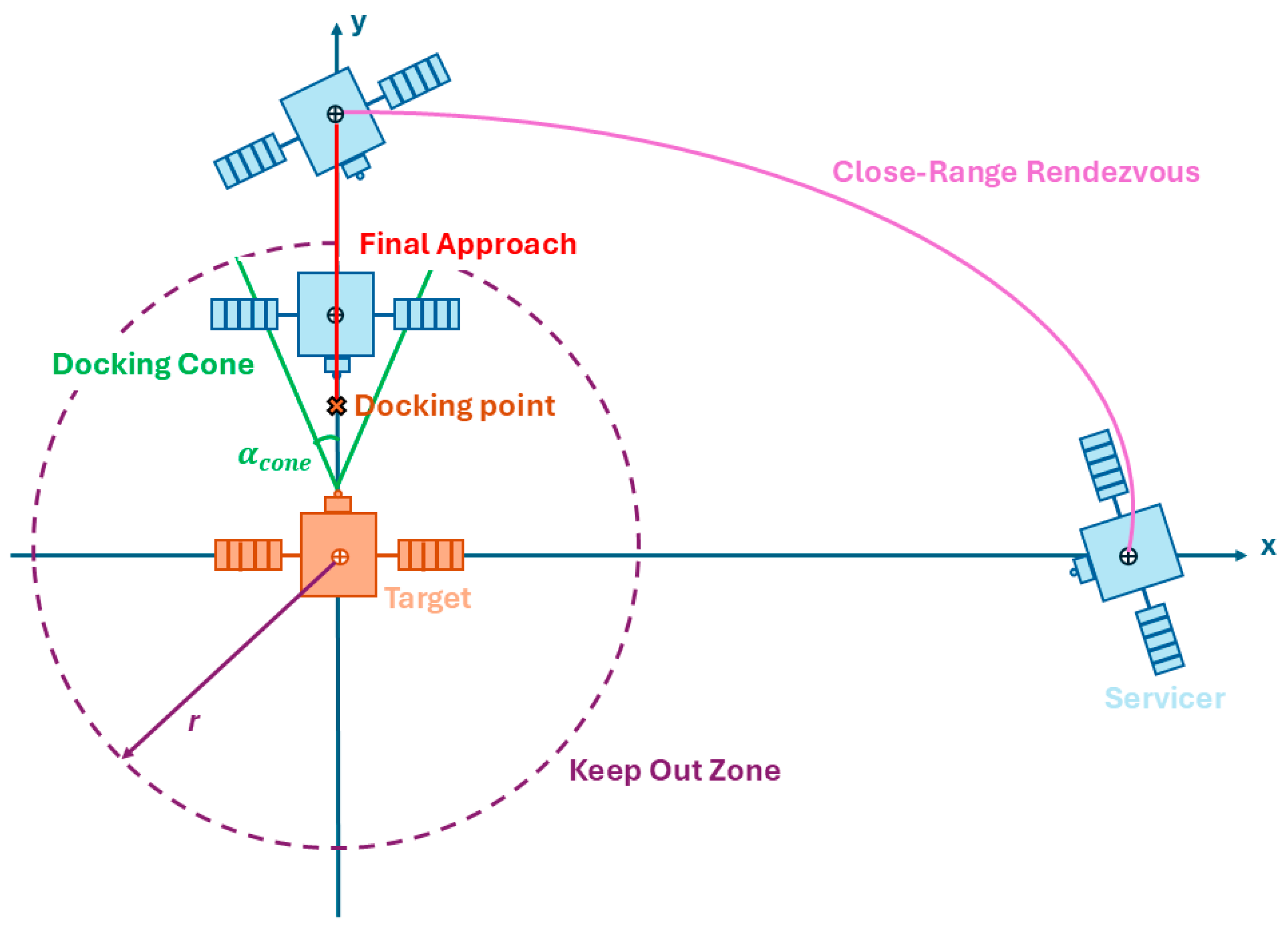
Figure 1 qualitatively depicts the two phases of the considered rendezvous scenario. For illustrative purposes, the servicer’s motion is confined to the radial–along-track plane.
  • Close-Range Rendezvous (CR): Starting at a distance of few tens of meters from the non-cooperative and tumbling space target, the servicer maneuvers toward the approach direction until it reaches a predetermined relative distance, while keeping the target within the LIDAR Field of View. Within the G&C algorithm, the translational and rotational motion are still treated as decoupled, thus operations are conducted in target pointing mode. The final position condition along the target’s approach direction is derived by propagating forward in time the target’s absolute rotational state, as estimated by the navigation function, over a time interval specified for the maneuver.
  • Final Approach Phase (FA): The servicer synchronizes with the tumbling motion of the target (Synchronization). This is followed by an intermediate stabilization phase to ensure stability. Subsequently, the servicer satellite moves along the designed approach direction until it reaches a predefined relative distance from the space target (docking/berthing point), at which capture operations can start (Closing). A final stabilization phase is then executed to ensure that the chaser has reached a stable condition, i.e., characterized by deviations from the desired terminal state below thresholds depending on capture constraints for a specified time interval.
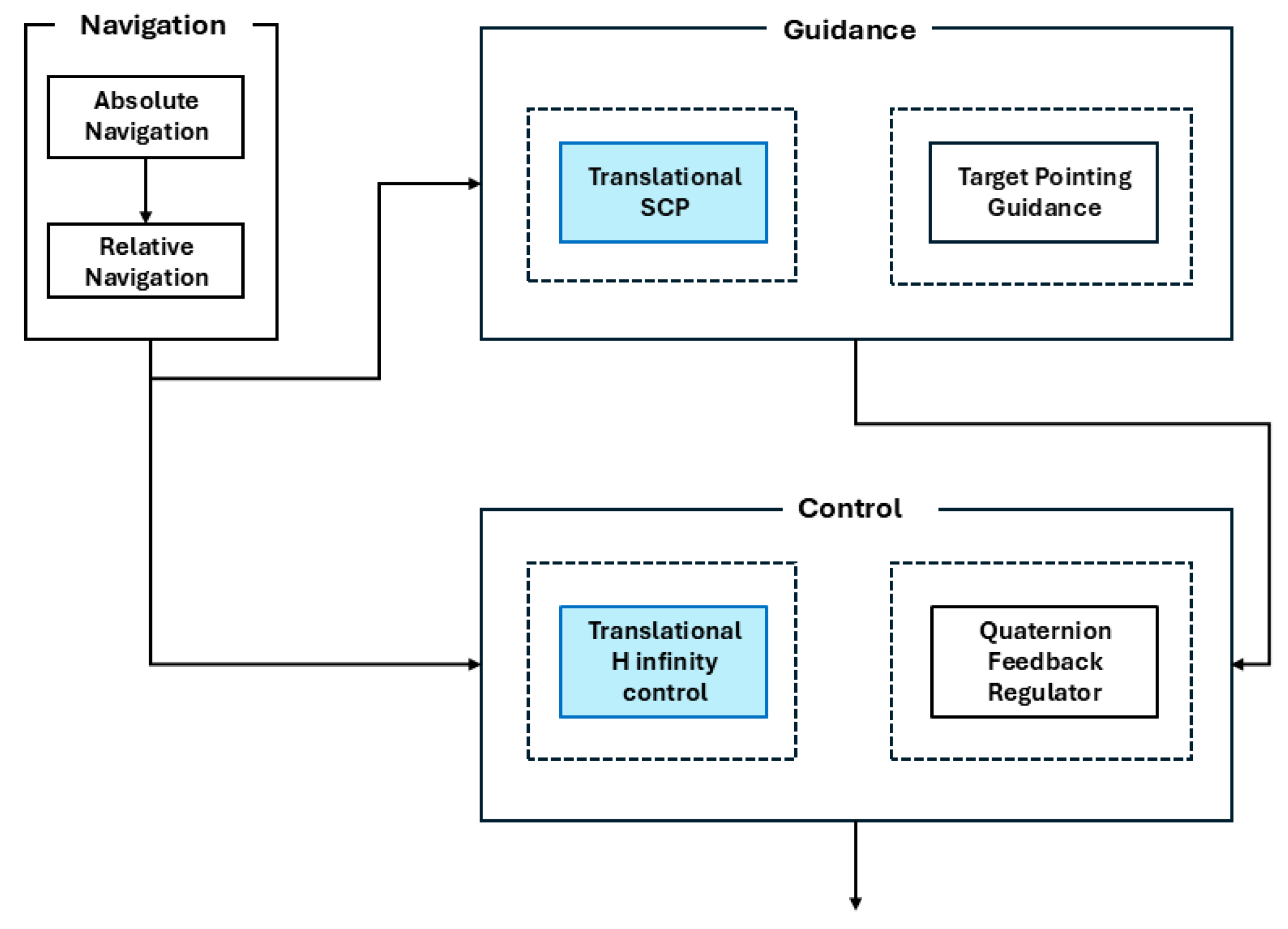
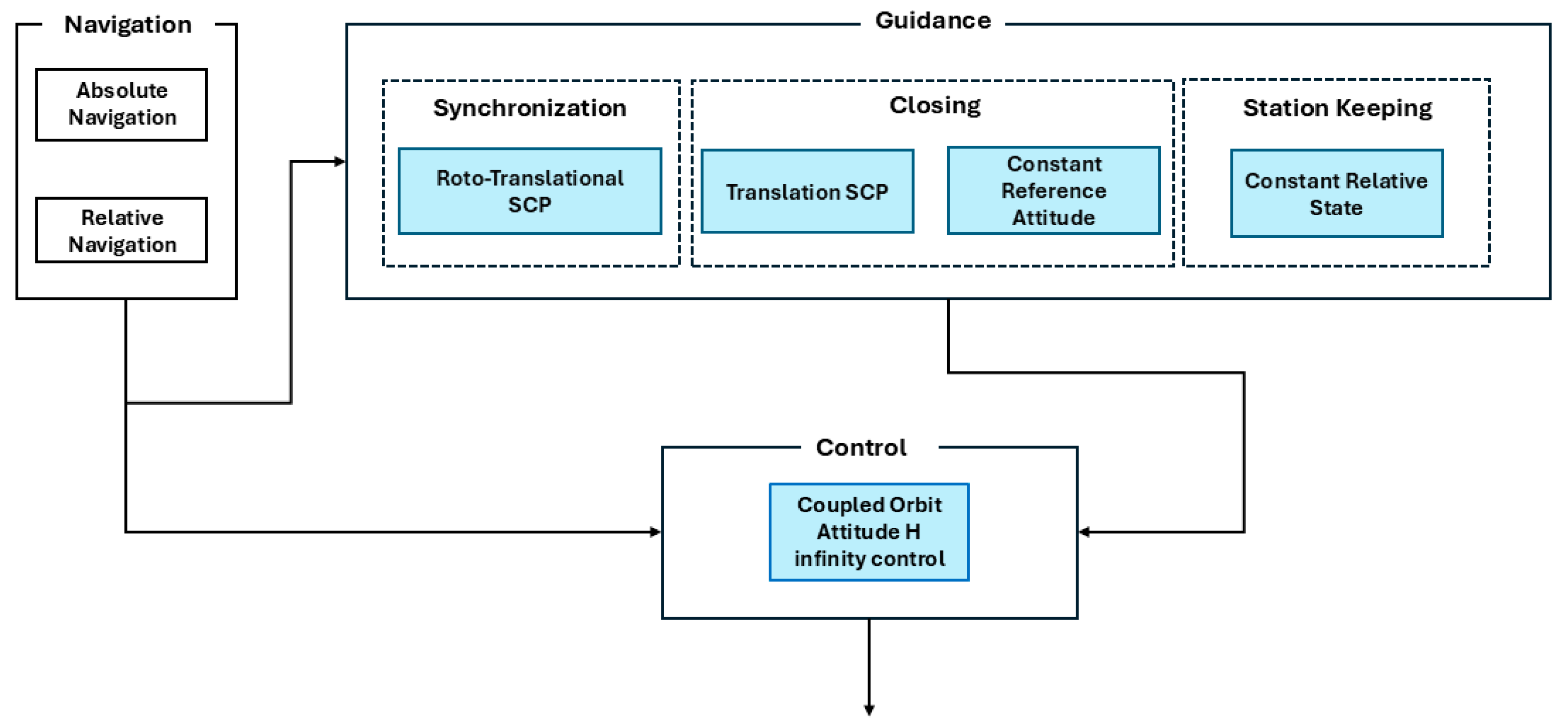
A schematic representation of the relative GNC architecture for the Close Range and Final Approach phases is shown in Figure 2 and Figure 3, respectively.
The navigation sub-system is the same for both maneuver phases. It relies on two navigation sub-blocks: Absolute Navigation and Relative Navigation. The first provides estimates of the chaser’s absolute state (position, velocity, attitude, and angular velocity), while the second outputs the target-chaser relative state using simulated LIDAR-based pose measurements and an MEKF. More details on the navigation functions are provided in Section 5.1. Instead, the G&C functions proposed in this work, highlighted in blue on the figures, are detailed in the following subsections.

3. Guidance Function

3.1. Close-Range Guidance

As mentioned in Section 2.2, the rotational and translational motion during the CR Phase is treated as decoupled, thus the chaser operates in target pointing mode. In this respect, the target pointing guidance function computes the desired chaser quaternion and angular velocity based on relative position and velocity estimates provided by the relative navigation function [42].
With regard to the translational problem, an SCP-based approach is adopted to determine a 3 degree of freedom nominal trajectory described by the following state vector, x p = r TRF SCRF HRF T v SCRF / TRF HRF T T . Its goal is to find the set of translational commands, i.e., nominal velocity increments ( Δ v SCRF / TRF HRF ) and their corresponding actuation time instants (tk), that minimize the propellant consumption while bringing the chaser from a given initial state (xp,0) to a given final state (xp,f), while satisfying a set of dynamics and operational constraints. The direct inputs of the optimization problem include xp,0, the initial (t0) and final (tf1) time (and, consequently, the duration of the maneuver), and the number of required commands set equal to N1 + 1, where N1 is the number of nominal jumps approximating a linear trajectory. Instead, xp,f is derived by imposing a constraint on the minimum target distance along its approach direction (d1) desired at the end of the CR maneuver. To this aim, the first task of the guidance function is to propagate the rotational motion of the target for the set maneuver time, i.e., tf1t0, starting from the last available estimate provided by the relative navigation function. Specifically, the attitude and angular velocity of the target are first propagated by integrating the Euler’s rotational dynamics equation coupled with the quaternion kinematic equation reported below:
q ˙ TRF / HRF = 1 2 ω TRF / HRF TRF 0 q TRF / HRF ω ˙ TRF / ECI TRF = I t 1 ω TRF / ECI TRF × I t ω TRF / ECI TRF
with
ω TRF / HRF TRF = ω TRF / ECI TRF R HRF TRF ω HRF / ECI H R F
where It is the target inertia tensor, while the rotation matrix R H R F T R F is computed from the corresponding quaternion using outputs of the absolute navigation function, namely q T R F / E C I and q E C I / H R F .
q T R F / H R F = q T R F / E C I q E C I / H R F
Consequently, the position and velocity components of xp,f = [ r TRF SCRF HRF t f 1 , v SCRF / TRF HRF t f 1 ]T are computed as follows,
r TRF SCRF HRF t f 1 = R TRF HRF t f 1 d 1 r APP
v SCRF / TRF HRF t f 1 = R TRF HRF t f 1 ω T R F / H R F T R F t f 1 × r TRF SCRF HRF t f 1
where r APP is the unit vector of the approach axis expressed in TRF.
Given such boundary conditions, the proposed SCP-based approach aims to iteratively find the minimum of a cost function (J), and it is formulated as follows, including path dynamics, Equation (9), boundary, Equation (10), collision avoidance, Equation (11), actuation, Equation (13), and thrust region, Equation (12), constraints.
min Δ v , ξ , η ( J ) = min Δ v , ξ , η k = 1 N 1 + 1 Δ v SCRF / TRF k HRF 1 + w η 1 k = 1 N 1 + 1 η k + w ξ 1 k = 1 N 1 + 1 ξ k
subject to
x p , k + 1 = A p , k x p , k + B p , k Δ v SCRF / TRF k HRF k = 1 , , N 1
x p t 0 = x p , 0 x p t f 1 = x p , f
g KOZ x p , ref k + g KOZ x p , ref k T x p k x p , ref k ξ k 0 ξ k 0 k = 1 , , N 1 + 1
x p . k x p , ref k 2 2 η k 0 k = 1 , , N 1 + 1
Δ v S C R F / T R F k H R F Δ v max k = 1 , , N 1 + 1
The collision avoidance constraint is defined by setting a region around the target that the chaser must not enter, commonly referred to as the Keep-Out Zone (KOZ). Since the KOZ is typically defined as a sphere with radius r1 corresponding to the maximum dimension of the target, the resulting constraint, reported below, is the only source of non-linearity in the optimization process
g KOZ x p = r 1 2 x p T 1 3 × 3 0 3 × 3 0 3 × 3 0 3 × 3 x p 0
where 13×3 is the identity matrix of size 3, and 03×3 is the zero matrix of size 3.
This constraint must be linearized at a reference trajectory (xp,ref) which represents the initial guess of the optimization process and is updated at each SCP iteration. The result of this linearization leads to Equation (11), where the following relation holds
g KOZ ( x p ) = 2 P KOZ x p ,
Regarding the other constraints, Δvmax is the maximum admissible linear velocity increments which represents actuators limitations. The path dynamics constraints are set using the Clohessy-Wiltshire (CW) equations, thus the state transition matrix (Ap) and the input matrix Bp of the system dynamics can be written as follows [43],
A p = 4 3 c 0 0 s n 2 n 1 c 0 6 ( s n Δ t ) 1 0 2 n ( 1 c ) 4 s 3 n Δ t / n 0 0 0 c 0 0 s / n 3 ns 0 0 c 2 s 0 6 n ( 1 c ) 0 0 2 s 4 c 3 0 0 0 ns 0 0 c
B p = A p 0 3 × 3 1 3 × 3
with,
c = cos ( n Δ t ) s = sin ( n Δ t )
where n is the orbital mean motion and Δt is the time step between successive nominal maneuvers.
Δ t = t f 1 t 0 N 1
Following the formulation proposed in [17], two penalties terms are added to the cost function of Equation (8). Specifically, they are indicated as trust region radius, ηk, and virtual buffer, ξk, and their contribution to the J is weighted by user-defined parameters, w η 1 and w ξ 1 . These penalty terms are introduced to mitigate the risk of artificial unfeasibility and artificial unboundedness. Specifically, the trust region constraint reported in Equation (12) allows keeping the solution within the region where the linearization is accurate, i.e., close to the reference one, thus avoiding artificial unboundedness. The virtual buffer is introduced in Equation (11) to relax the convexified collision avoidance constraint to avoid artificial infeasibility. In fact, if the initial reference trajectory is far from the feasible region of the original non-linear problem, the solution of the linear one that satisfies the convexified path constraints may lie outside the trust region thus being unfeasible.
For the sake of SCP implementation, the optimization problem is solved by employing a gradient-based non-linear programming solver. To reduce the risk of numerical instabilities, all the physical quantities are made dimensionless, using the Earth radius as distance unit, and the Earth rotational Period as time unit.
At the first iteration, the initial guess is obtained by solving the minimum energy problem, Equation (8), subject only to the boundary conditions, Equation (10). Starting with this solution, the SCP algorithm computes the desired reference trajectory that satisfies all the constraints.
Instead, the iterative process is ended when the following convergence criterion is satisfied,
x p x p , ref ε x Δ J ε J
where ΔJ is the difference in cost functions between consecutive iterations, while εx and εJ are user-defined convergence thresholds.
Once the SCP has converged, the trajectory can be sampled at the desired time step, typically depending on the GNC frequency, by propagating the CW equations.

3.2. Final Approach Guidance

As mentioned in Section 2.2, the rotational and translational motion during the final approach phase are treated as coupled, thus the chaser operates in attitude pointing mode. First, an SCP-based approach is adopted to determine a roto-translational reference trajectory ensuring synchronization between the target and chaser relative motion (Section 3.2.1). Subsequently, the guidance function computes the nominal trajectory that drives the chaser along the target’s approach axis up to the docking point (closing) using again a purely translational SCP-based solver (Section 3.2.2). At the end of both synchronization and closing phases, a roto-translational station keeping strategy is adopted to ensure adequate stabilization before starting to the next step (Section 3.2.3).

3.2.1. Synchronization

During the Synchronization Phase, the servicer satellite synchronizes with the tumbling motion of the space target.
This phase presents significant challenges, as the chaser must estimate the target’s rotational state in real time, while the actuation system must execute precise and agile control actions. Furthermore, the feasibility of this phase is strongly influenced by the current rotational state of the target, specifically, higher angular velocities make synchronization more arduous.
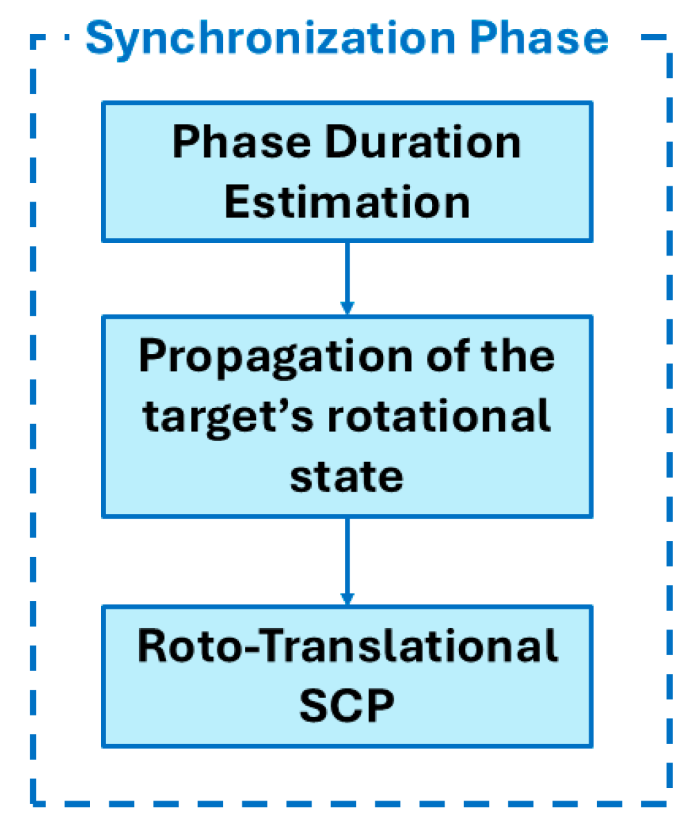
The execution order of the guidance functions implemented for the Synchronization Phase is illustrated in Figure 4 and described in the remainder of this subsection.
A key original contribution of this work is related to the fact that the duration of the synchronization phase (tf2) and consequently of the corresponding roto-translational maneuver is adaptively computed based on current available estimates from the navigation function, instead of being a freely selectable tuning parameter. This is performed to ensure that the synchronization maneuver is feasible especially when dealing with fast tumbling targets. Specifically, tf2 is calculated as the time interval required by the approach axis in HRF to reach again its initial position up to a specified angular tolerance, φdes (related to the non-perfect repeatability of the target polhode). Starting from the current estimate of the target’s attitude and angular velocity, [ q T R F / H R F t init   T ω T R F / E C I T R F t init   T ]T, provided by the relative navigation filter, Equations (3) and (4) are propagated over an orbital period with a step interval equal to the GNC frequency. Then, for each sample time, the angle between the predicted direction of the approach axis expressed in HRF, r APP , t i and the initial one, r APP , t init , indicated as φ, is compared with φdes. When φ < φdes, the corresponding sample time is selected as tf2. However, this time duration must be within a range defined by a minimum (tf2,min) and a maximum value (tf2,max). If this range is exceeded, the time duration is set to a fixed and predefined value (tf2,fix).
In addition to the translational target-chaser motion parameters as defined in Section 3.1, the state vector x describing the nominal trajectory to be estimated includes a rotational part, xr, composed by the Gibbs vector gSCRF/HRF representing the chaser relative attitude with respect to HRF and the absolute angular velocity, ω SCRF / ECI SCRF ,
x = x p T x r T T
Besides tf2, other inputs of the SCP-based trajectory generation process are the number of nominal maneuvers, N2 + 1. The boundary conditions on the translational state vector are set as in Equations (6) and (7) while, given the desired relative attitude ( q SCRF / TRF des ) and angular velocity ( ω SCRF / TRF des SCRF ), the final boundary conditions for the rotational state vector are set by exploiting the propagated rotational state of the target, as shown in Equation (22).
q SCRF / HRF t f 2 = q SCRF / TRF des q TRF / HRF t f 2 ω SCRF / ECI SCRF t f 2 = ω SCRF / TRF des SCRF R TRF SCRF t f 2 ω TRF / ECI TRF t f 2
The Gibbs vector can be obtained from the quaternion representation using Equation (1).
All elements of the SCP algorithm are made dimensionless using the same logic defined in Section 3.1.
Considering the impulse vector which contains the corresponding linear velocity ( Δ v SCRF / TRF k HRF ) and angular velocity ( Δ ω SCRF / ECI k SCRF ) increments, the SCP-based approach is formulated as an energy-minimization problem. The objective is minimizing the maneuver’s energy cost (Equation (23)) while satisfying the path dynamics (Equation (24)), boundary (Equation (25)), collision avoidance (Equation (26)), target visibility (Equation (27)), thrust region (Equation (28)) and actuation (Equation (29)) constraints, as follows
min Δ v , Δ ω , ξ , η ( J ) = min Δ v , Δ ω , ξ , η k = 1 N 2 + 1 Δ v SCRF / TR F k HRF 1 + Δ ω SCRF / EC I k SCRF 1 + w η 2 k = 1 N 2 + 1 η k + + w ξ 2 k = 1 N 2 + 1 ξ KOZ , k + ξ FOV , k
Subject to
x k + 1 = A k x k + B k u k + D k c k k = 1 , , N 2
x t init = x 0 x t f 2 = x f
g KOZ x p , ref k + g KOZ x p , ref k T x p , k x p , ref k ξ KOZ , k 0 ξ KOZ , k 0 k = 1 , , N 2 + 1
g F O V x ref , k + g FOV x ref , k T x k x ref , k ξ FOV , k 0 ξ FOV , k 0 k = 1 , , N 2 + 1
x k x ref , k 2 2 η k 0 k = 1 , , N 2 + 1
Δ v S C R F / T R F k H R F Δ v max Δ ω S C R F / E C I k S C R F Δ ω max k = 1 , , N 2 + 1
As for the Close-Range Guidance, the non-convex constraints, i.e., target visibility, dynamics and collision avoidance constraints are presented directly in their convexified form. The matrices Ak, Bk, Dk and vector ck in Equation (24) are detailed in Section Dynamics Constraints. Equation (27) represents the convexification form of the target visibility constraint. Generally, during the Final Approach phase, the target must be maintained within the FOV of the LIDAR. This condition can be expressed by the following nonlinear relation,
cos FOV 2 R HRF SCRF r TRF SCRF HRF r SCRF LRF SCRF T b R HRF SCRF r TRF SCRF HRF r SCRF LRF SCRF 2 0 ,
The function gFOV, defined in Equation (27) is obtained from Equation (31), as follows,
g F O V = R HRF SCRF r TRF SCRF HRF + r SCRF LRF SCRF T b R HRF SCRF r TRF SCRF HRF + r SCRF LRF SCRF 2 ,
The linearization of the function gFOV is outlined in [18].
The SCP problem is initialized with a reference solution obtained by decoupling the rotational and translational sub problems:
The translational initial guess is obtained by solving the translational optimal sub-problem considering only the boundary constraints (Equation (25)), as described for the translation SCP-based approach in Section 3.1.
The rotational reference solution is obtained assuming linear variation in relative attitude between the rotational-state boundary conditions.
The same convergence criterion as in Equation (20) is adopted.
Once the Roto-translational SCP has converged, a nominal trajectory sampled at GNC frequency is obtained by propagating the CW equations, the quaternion-based attitude kinematics equations and Euler’s rotational equations [41].
Dynamics Constraints
The matrices Ak, Bk, Dk, and vector ck in Equation (24) can be decomposed into different terms related to the translational and rotational part of the state vector.
A k = A p , k 0 6 × 6 0 6 × 6 A r , k B k = B p , k 0 3 × 3 0 3 × 3 B r , k D k = 0 6 × 6 D r , k
The matrices Ap,k and Bp,k are defined in Equation (16), while the calculation of matrices Ar,k, Br,k and Dr,k follows the methodology outlined in [39], with the distinction that impulsive thrusters are considered in this present work. Consequently, in this paper, the attitude kinematics (expressed in terms of Gibbs vector) and the rotational dynamics (Euler’s equation) are described as follows,
x ˙ r = f r x r + 0 3 × 3 I c 1 T c ,
where Tc is the torque exerted on the chaser and expressed in SCRF and fr is a nonlinear function,
f r = 1 2 ω SCRF / HRF SCRF ω SCRF / HRF SCRF × g SCRF / HRF + ω SCRF / HRF SCRF T g SCRF / HRF g SCRF / HRF I c 1 ω SCRF / ECI SCRF × I c ω SCRF / ECI SCRF ,
Ic is the chaser’s inertia tensor and ω SCRF / HRF SCRF is computed as done in Equation (4).
Equation (33) is discretized and linearized around the rotational component of the reference trajectory xr,ref, computed at the previous iteration,
x r , k + 1 = A r , k x r , k + B r , k Δ ω SCRF / ECI k SCRF + D r , k c r , k k = 1 , , N 2 ,
with
A r , k = Φ r , k B r , k = Φ r , k 0 3 × 3 1 3 × 3 D r , k = t k t k + 1 Φ r , k t k + 1 ρ d ρ c r , k = f r x r , ref k Λ r , k x r , ref k
and
Φ r , k = e Λ r , k Δ t Λ r , k = f r x r , ref
where Δt is defined in Equation (19).

3.2.2. Closing Phase

During this phase, the chaser translates towards the target within the docking cone while strictly maintaining a constant desired relative attitude ( q SCRF / TRF des ) and zero relative angular velocity, ( ω SCRF / TRF des SCRF ). In this way, the FOV constraint is inherently satisfied.
In Closing Phase, the SCP-based approach is employed to determine the 3 degree of freedom nominal trajectory, described by the state vector defined in Section 3.1, [ r TRF SCRF HRF T v SCRF / TRF HRF T ]T.
Besides tf3, another input to the SCP process is the number of nominal maneuvers, N3 + 1. The final boundary conditions on the translational state vector are defined as in Equations (6) and (7).
Considering the impulse vector which contains the corresponding linear velocity ( Δ v SCRF / TRF k HRF ) increments, the SCP-based approach is formulated to minimize the propellant consumption (Equation (38)). The optimization problem is subject to path dynamics (Equation (39)), boundary conditions (Equation (40)), collision avoidance (Equation (41)), docking cone (Equation (42)), thrust region (Equation (43)) and actuation (Equation (44)) constraints, as follows.
min Δ v , ξ , η ( J ) = min Δ v , ξ , η k = 1 N 3 + 1 Δ v SCRF / TRF k HRF 1 + w η 3 k = 1 N 3 + 1 η k + w ξ 3 k = 1 N 3 + 1 ξ KOZ , k + ξ CONE , k
Subject to
x p , k + 1 = A p , k x p , k + B p , k Δ v SCRF / TRF k HRF k = 1 , , N 3 1
x p t init = x p 0 x p t f 3 = x pf
g KOZ x p , ref k + g KOZ x p , ref k T x p k x p , ref k ξ KOZ , k 0 ξ KOZ , k 0 k = 1 , , N 3
g CONE x p , ref k + g CONE x p , ref k T x p k x p , ref k ξ CONE , k 0 ξ CONE , k 0 k = 1 , , N 3
x p k x p , ref k 2 2 η k 0 k = 1 , , N 3
Δ v SCRF / TRF k HRF 2 Δ v max k = 1 , , N 3
Even in this case, the non-convex constraints, i.e., docking cone, dynamics and collision avoidance constraints are presented directly in their convexified form. The matrices Ak and Bk, in Equation (39), are described in Section 3.1. Equation (42) represents the convexified form of the docking cone constraint. In fact, during the Closing, the servicer shall move within the docking cone of the target. From a mathematical point of view, this condition can be expressed by the following nonlinear relation [18],
g CONE = cos α CONE R HRF TRF P CONE x p r TRF DOCK TRF T r APP R HRF TRF P CONE x p r TRF DOCK TRF 0
with
P CONE = 1 3 × 3 0 3 × 3
where αCONE is the half-angle of the approach corridor, defined in Figure 1, r TRF DOCK TRF is the final desired position expressed in TRF, and r APP is the approach axis expressed in TRF, as seen in Section 3.1. The convexification of this constraint follows the same methodology as that described in [18].
At the first iteration, the initial guess is obtained by solving the minimum energy problem of Equation (38) subject only to the boundary conditions (40), as done in Section 3.1. The same convergence criterion, defined in Equation (20), is adopted.

3.2.3. Station Keeping

Stabilization at the end of synchronization and closing phases is ensured by a station keeping guidance function. Specifically, the chaser needs to keep a constant relative distance from the target along the approach axis with zero relative velocity expressed in TRF,
r TRF SCRF d e s TRF = d i r APP r ˙ TRF SCRF d e s TRF = 0 i = 2 , 3 r TRF SCRF HRF = R TRF HRF r TRF SCRF d e s TRF r ˙ TRF SCRF HRF = R TRF HRF ω TRF / HRF TRF × r TRF SCRF HRF
where the relative velocity expressed in HRF is obtained by performing a time derivation of the relative position vector, r TRF SCRF HRF [44].
Furthermore, the servicer shall maintain a constant relative attitude ( q SCRF / TRF des ) with zero relative angular velocity, ( ω SCRF / TRF des SCRF ). The duration of these phases depends on the onboard tracking errors, defined as the difference between the nominal trajectory, provided by the guidance function, and estimated state, provided by the navigation function. It terminates when the tracking errors remain below user defined thresholds for a pre-specified period.

4. Control Function

This section describes the proposed H infinity controller which allows tracking a purely translational trajectory during the CR rendezvous phase (Section 4.1) and a roto-translational one during the Final Approach phase (Section 4.2).

4.1. Translational Control

The proposed translational control function has two main task. During the execution of nominal maneuvers, it computes the forces corresponding to the nominal linear velocity provided by the guidance function, which are sent to the dispatching function to determine the action requested to the actuators.
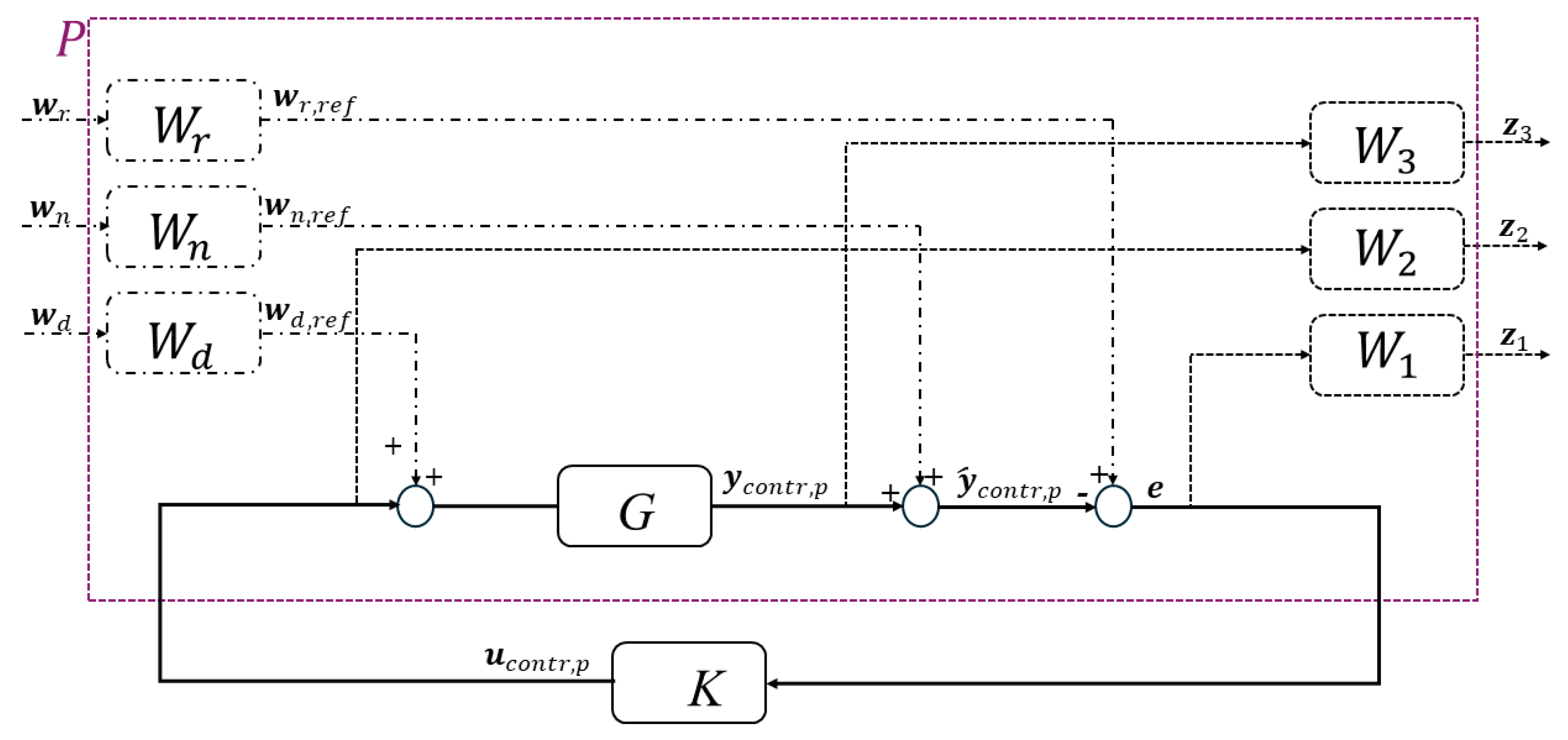
In absence of nominal maneuvers, an H infinity controller is used to perform the trajectory tracking task, i.e., to determine the control forces required to nullify the deviation from the nominal relative position and velocity computed by the guidance function. The generic structure of the controller is reported in Figure 5, as outlined in [34].
G is the transfer function of the plant which relates the input ucontr,p, i.e., the control forces, with the observable variables ycontr,p. The state vector of the translation H infinity controller (xcontr,p) is composed by the target-chaser relative position, r TRF SCRF HRF , and relative velocity, v SCRF / TRF HRF . The plant G is represented by the space-state model corresponding to the following first-order dynamical system,
x ˙ c o n t r , p = A contr , p x c o n t r , p + B contr , p u contr , p y c o n t r , p = C contr , p x c o n t r , p + D contr , p u contr , p
where Acontr,p, Bcontr,p, Ccontr,p and Dcontr,p are obtained from the CW equations [45],
A contr , p = 0 3 × 3 1 3 × 3 3 n 2 0 0 0 0 0 0 0 n 2 0 2 n 0 2 n 0 0 0 0 0 B c o n t r , p = 0 3 × 3 1 m c 1 3 × 3 C contr , p = 1 6 × 6 D contr , p = 0 6 × 3
where mc is the mass of the chaser. P denotes the augmented plant with three exogenous inputs wr, wn and wd, representing the nominal state, measurement noise and disturbances on actuated force, respectively, and with three exogenous outputs z1, z2 and z3, representing the error e, control input ucontr,p and plant output ycontr,p, respectively. Each exogenous input is weighted through the transfer functions Wr, Wn and Wd, in contrast, each exogenous output is weighted through the transfer functions W1, W2 and W3. The block diagram reported in Figure 5 can be formulated as follows,
z e = P 11 P 12 P 21 P 22 w u c o n t r , p
The relationship between the exogenous output z (consisting of z1, z2 and z3) and the exogenous input w (consisting of wr, wn and wd) can be rewritten in the following form, as outlined in [46],
z = F P , K w , where F P , K = W 1 S W r W 1 S W n W 1 S G W d W 2 K S W r W 2 K S W n W 2 K S G W 3 T W r W 3 T W n W 3 S G W d S = I + G K 1 T = I S
where I is the unitary transfer function, S is the sensitivity matrix, and T is the complementary sensitivity matrix. The objective of the H infinity synthesis is determining the gain K in order to minimize the effect of the disturbances on the performance output vector,
K * = argmin K F P , K ,
where K* is the desired optimal value of the control gain K.

4.2. Roto-Translational Control

This function is used for trajectory tracking during the Final Approach phase. Again, if nominal maneuvers are requested, it only computes the required forces and torques, corresponding to the nominal linear and angular velocity increments produced by the guidance function. When no nominal maneuver is commanded, the function provides the control forces and torques required to nullify the deviation from the nominal roto-translational trajectory provided by the guidance function.
The block diagram is the same of Figure 5, but in this case, the control input vector, ucontr, encompasses the total force and torque exerted onto the system. The plant G is represented by a similar space-state model, where the state vector of roto-translational H infinity control, xcontr, includes the relative position ( r TRF SCRF HRF ), velocity ( v SCRF / H R F HRF ), relative attitude ( g SCRF / TRF ) and relative angular velocity ( ω SCRF / TRF SCRF ),
x ˙ contr = A contr x contr + B contr u contr y = C contr x contr + D contr u contr ,
The matrices Acontr, Bcontr, Ccontr and Dcontr are defined as follows:
A contr = A contr , p 0 6 × 6 0 6 × 6 A contr , r B contr = B contr , p 0 6 × 3 0 6 × 3 B contr , r C contr = 1 12 × 12 D contr = 0 12 × 6 ,
Acontr,p and Bcontr,p are given again by Equation (49), as it is possible to use the CW equation to model the relative translational dynamics. Instead, Acontr,r and Bcontr,r are obtained from the linearization of the relative rotational dynamics equations.
The first step is to derive the expression for the relative angular acceleration, which can be formulated as presented in [47],
ω ˙ SCRF / TRF SCRF = ω ˙ SCRF / ECI SCRF R TRF SCRF ω ˙ TRF / ECI TRF R TRF SCRF ω TRF / ECI TRF × ω SCRF / TRF SCRF
This expression is obtained by differentiating the relative angular velocity,
ω SCRF / TRF TRF = ω SCRF / ECI SCRF R TRF SCRF ω TRF / ECI TRF
The absolute angular accelerations of both chaser and target in Equation (55) can be described using the Euler’s rotation equation for a rigid body,
I c ω ˙ SCRF / ECI SCRF = ω SCRF / ECI SCRF × I c ω SCRF / ECI SCRF + T c ,
I t ω ˙ TRF / ECI TRF = ω TRF / ECI TRF × I t ω TRF / ECI TRF
The absolute angular velocity of the chaser, as given in Equation (57), can be re-written in terms of the relative angular velocity, target’s angular velocity and relative attitude, using Equation (56),
ω SCRF / ECI SCRF = ω SCRF / TRF TRF + R TRF SCRF ω TRF / ECI TRF
Consequently, substituting Equation (59) into Equation (57), the chaser’s angular acceleration becomes,
I c ω ˙ SCRF / ECI SCRF = ω SCRF / TRF SCRF + R TRF SCRF ω TRF / ECI TRF × I c ω SCRF / TRF SCRF + R TRF SCRF ω TRF / ECI TRF + T c ,
The cross product in Equation (60) can be rewritten as,
ω SCRF / TRF SCRF + R TRF SCRF ω TRF / ECI TRF × I c ω SCRF / TRF SCRF + R TRF SCRF ω TRF / ECI TRF = = ω SCRF / TRF SCRF × I c ω SCRF / TRF SCRF + R TRF SCRF ω TRF / ECI TRF + R TRF SCRF ω TRF / ECI TRF × I c ω SCRF / TRF SCRF + R TRF SCRF ω TRF / ECI TRF = I c ω SCRF / TRF SCRF + R TRF SCRF ω TRF / ECI TRF × ω SCRF / TRF SCRF + R TRF SCRF ω TRF / ECI TRF × I c ω SCRF / TRF SCRF + R TRF SCRF ω TRF / ECI TRF = I c ω SCRF / TRF SCRF + R TRF SCRF ω TRF / ECI TRF × + R TRF SCRF ω TRF / ECI TRF × I c ω SCRF / TRF SCRF + R TRF SCRF ω TRF / ECI TRF × I c R TRF SCRF ω TRF / ECI TRF
By left-multiplying both sides of Equation (55) by the chaser’s inertia tensor and substituting Equations (60) and (58) into Equation (55), the expression for the relative angular acceleration is derived,
I c ω ˙ SCRF / TRF SCRF + + I c R T R F S C R F ω TRF / ECI TRF × + R T R F S C R F ω TRF / ECI TRF × I c I c ω SCRF / TRF SCRF + R T R F S C R F ω TRF / ECI TRF × ω SCRF / TRF SCRF + + R T R F S C R F ω TRF / ECI TRF × I c R T R F S C R F ω TRF / ECI TRF I c R T R F S C R F I t 1 ω TRF / ECI TRF × I t ω TRF / ECI TRF = T c
This can be compactly written as,
I c ω ˙ SCRF / TRF SCRF + C r ω SCRF / TRF SCRF ω SCRF / TRF SCRF + n r = T c
with
C r ω SCRF / TRF SCRF = I c R T R F S C R F ω TRF / ECI TRF × + R T R F S C R F ω TRF / ECI TRF × I c I c ω SCRF / TRF SCRF + R T R F S C R F ω TRF / ECI TRF ×
n r = R T R F S C R F ω TRF / ECI TRF × I c R T R F S C R F ω TRF / ECI TRF I c R T R F S C R F I t 1 ω TRF / ECI TRF × I t ω TRF / ECI TRF
The relative attitude kinematics, on the other hand, is formulated using the Gibbs vector [41],
g ˙ SCRF / TRF = 1 2 ω S C R F / T R F S C R F 1 2 ω S C R F / T R F S C R F × g SCRF / TRF + 1 2 g SCRF / TRF ω S C R F / T R F S C R F T g SCRF / TRF ,
Finally, the relative angular dynamics (Equation (62)) and the relative attitude kinematics (Equation (66)) can be combined into the following nonlinear function, ς,
g ˙ SCRF / TRF ω ˙ SCRE / TRF SCRF = ς g SCRF / TRF , ω SCRF / TRF SCRF , ω TRF / ECI TRF , T c ,
This non-linear function can be linearized using Taylor series expansion around a reference point, pref = g SCRF / TRF r e f T ω SCRF / TRF r e f SCRF T ω TRF / ECI r e f TRF T T r e f T T ,
ς g SCRF / TRF , ω SCRF / TRF SCRF , ω TRF / ECI TRF , T c ς p ref + + ς g p r e f g SCRF / TRF g SCRF / TRF r e f + ς ω p r e f ω SCRF / TRF SCRF ω SCRF / TRF r e f SCRF + ς T p r e f T c T r e f ,
Consequently, Acontr,r, defined in Equation (54), is obtained by the linearization of Equation (68) as follows:
A contr , r = A contr , r 11 A contr , r 12 A contr , r 21 A contr , r 22 ,
A contr , r 11 = g ˙ S C R F / T R F g S C R F / T R F p r e f A contr , r 12 = g ˙ S C R F / T R F ω S C R F / T R F S C R F p r e f A contr , r 21 = ω ˙ S C R F / T R F S C R F g S C R F / T R F p r e f A c ontr , r 22 = ω ˙ S C R F / T R F S C R F ω S C R F / T R F S C R F p r e f
The choice of the reference point for the linearization of the relative rotational dynamics, denoted as pref, and, consequently for the synthesis of the 6DOF H infinity controller, plays a critical role in determining the trajectory tracking performance. Indeed, the actual relative rotational state can significantly deviate from this point due to the tumbling motion of the target. Concerning the relative attitude ( g SCRF / TRF ref ) and angular velocity ( ω S C R F / T R F r e f S C R F ), these are set equal to the desired ones ( g SCRF / TRF des and ω S C R F / T R F d e s S C R F ) at the end of the closing maneuver (see details in Section 5.2). Clearly the true operating conditions in terms of relative attitude and angular velocity may vary significantly during the Final Range maneuver thus causing a deviation from the operating point at which the controller is designed. However, this choice allows the controller to work close to the reference design point at the end of the rendezvous operations when it is more critical to get high trajectory tracking accuracy.
The definition of the operative point also includes the selection of the target angular velocity. Given a maximum norm of the target absolute angular velocity (ωmax), and considering that this vector can be initially pointed in any direction, it is convenient to set ω TRF / HRF ref TRF to a null vector, thus making ω TRF / ECI ref TRF equal to the orbital angular velocity. Indeed, since no information on the target initial attitude at start of the Final Approach phase is available, this setting allows keeping bounded the maximum deviation from the reference point at which the controller initially operates. Finally, the reference torque, Tref, is set to 03×1, as suggested in [34].
When no nominal maneuvers are commanded, the H infinity controller computes the actions required to nullify the tracking error, represented by the vector e in Figure 5. This error is defined as the difference between the estimated and nominal state. In particular, the relative attitude error is computed as follows,
q SCRF / TRF err = q SCRF / TRF q ^ SCRF / TRF 1 ,
where qSCRF/TRF is the nominal relative attitude quaternion generated by the guidance function, while the superscript −1 denotes the quaternion inverse. From Equation (71), the equivalent Gibbs vector error is then calculated using Equation (1).
To evaluate this tracking error, the nominal trajectory computed by the guidance function must be available. As previously discussed, the state vector of the H infinity controller includes the relative position and velocity (expressed in HRF), the relative attitude and angular velocity. However, the roto-translational SCP algorithm, defined in Section 3.2.1, provides the time history of the translational state vector, i.e., the relative position and velocity along with the chaser’s attitude with respect to HRF, g SCRF / HRF , and absolute angular velocity ( ω SCRF / ECI SCRF ). To align this SCP-generated trajectory with the controller’s state, the attitude and angular velocity are combined with the information of the relative navigation function, according to
q SCRF / TRF = q SCRF / HRF q ^ HRF / TRF ω SCRF / TRF SCRF = ω SCRF / ECI SCRF R ^ T R F S C R F ω ^ TRF / ECI TRF
In general, the quaternion vector, required in Equation (72), corresponding to the Gibbs vector, is computed using the following relantinship [41],
q = 1 1 + g T g g 1

5. Simulation Environment and Scenario Definition

5.1. Simulation Environment

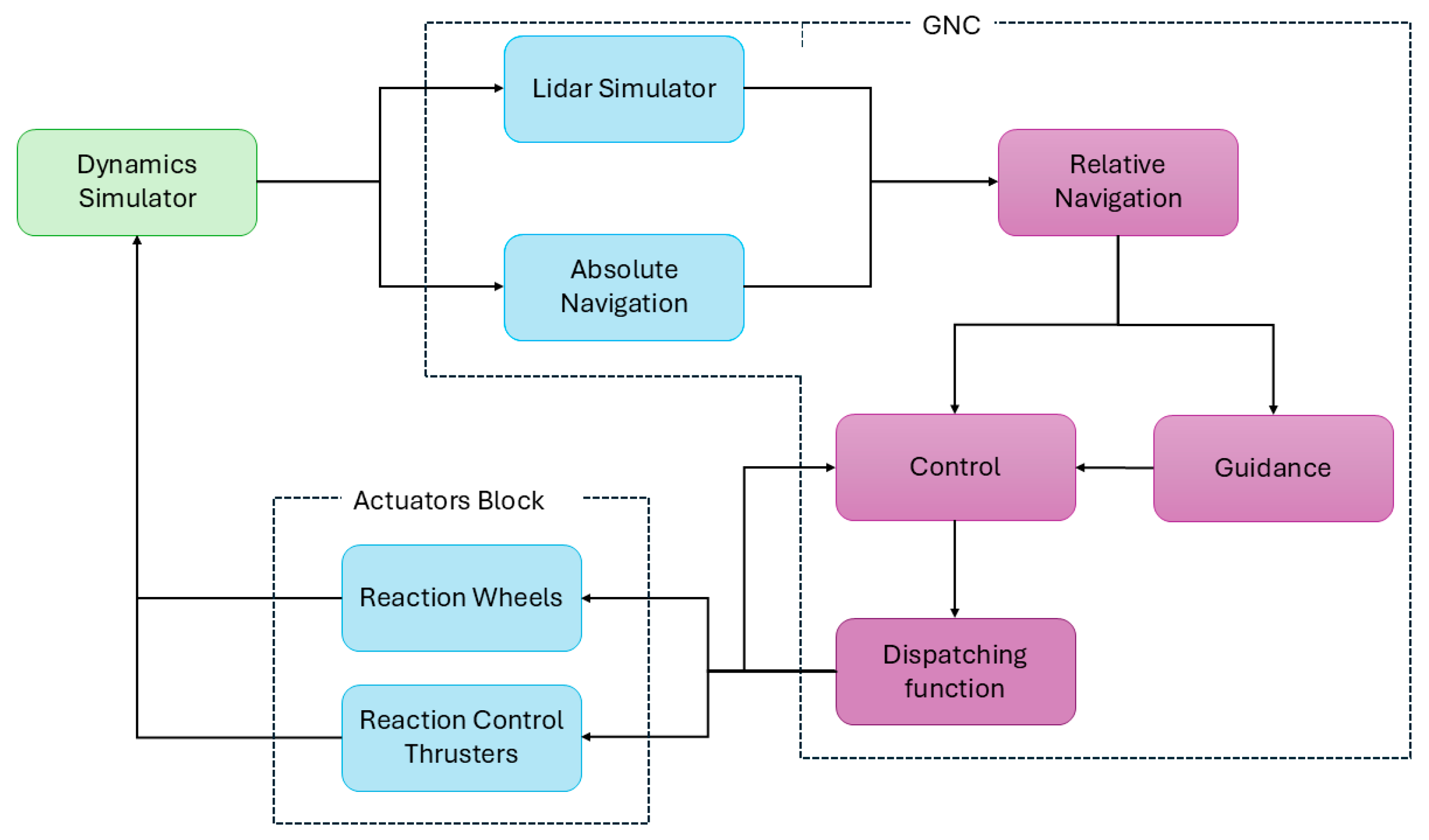
The block diagram of the simulation environment developed to assess performance of the proposed G&C methodologies is shown in Figure 6. It comprises three primary components.
1.
Dynamics simulator block.
2.
GNC block, which includes:
  • Guidance Function.
  • Control Function.
  • Relative Navigation Function.
  • Absolute Navigation Function.
  • LIDAR-based pose measurement simulator.
  • Dispatching Function.
3.
Actuators block, which includes:
  • Reaction Wheels model.
  • Reaction Control Thrusters model.
The main task of Dynamics Simulator block is to reproduce the true orbital and rotational dynamics of the chaser and the target. With regard to orbital dynamics, the time variation in the true position and velocity of the two objects in ECI is obtained using a numerical propagator which includes the effects of gravitational field, third-body perturbations caused by the Sun and the Moon, atmospheric drag, and solar radiation pressure, in addition to the accelerations applied by the Reaction Control System. A synthesis of the parameters employed to model these effects is provided in Table 1. Instead, the rotational dynamics of the chaser and target is propagated by solving the attitude kinematics and Euler’s equation to obtain the time evolution of the true attitude and angular velocity of the two satellites. It includes the effects caused by gravity, atmospheric drag and solar radiation pressure. With reference to the last two effects, torques are determined by applying the force contribution of each planar surface to its center.
Although the proposed Guidance and Control algorithms are developed using simplified dynamic models, namely, the Clohessy-Wiltshire equations for translational motion and Euler’s equations for rotational dynamics, the dynamics simulator incorporates also relevant perturbations, e.g., non-sphericity of the Earth and Atmospheric Drag, as detailed in Table 1. These perturbations are relatively limited due to the short mission duration and the operating altitude. However, their introduction defines a more realistic simulation environment and provides a stronger demonstration of robustness and effectiveness of the proposed G&C algorithms, as discussed in Section 6.
The Absolute Navigation state estimates are simulated by adding an error extracted from a zero-mean Gaussian distribution to the true absolute navigation state. The standard deviations which characterize the Gaussian distributions are selected considering the expected performance of the absolute navigation function, as reported in Table 2. Noise correlation is introduced by applying a first-order time-discrete low-pass filter [48], whose transfer function can be written in the complex domain as follows,
H z = b 1 a z 1
Weights a and b are set to 0.99 and 1, respectively, in order to ensure high cut-off frequency while avoiding an alteration of the amplitude of the transfer function.
Similarly, the LIDAR-based pose measurement simulator consists of adding a gaussian noise to the true target-chaser pose parameters, with characteristics outlined in Table 3 [49,50]. Relative state estimation is performed using a Multiplicative Extended Kalman Filter, whose state vector includes the target-chaser relative position and velocity, the target-chaser relative attitude quaternion and target angular velocity [51]. The MEKF prediction step relies on the Clohessy Wiltshire equations for the relative translational dynamics, while the rotational dynamics process model employs quaternion attitude kinematics equation coupled with the Euler’s equation for a free rigid body. The MEKF correction step, instead, relies on an observation model based on the equations relating the LIDAR-based pose measurements to the filter state.
The Dispatching Function allows converting the forces and torques computed by the control function into commands for the actuators. The dispatching logic prescribes that the commanded forces are exerted by Reaction Control Systems, while the torques are exerted by a combination of Reaction Wheels and RCS. For each control action commanded to the RCS, the dispatching function shall identify which thruster must be active, and the duration of the firing action. To determine the distribution of commanded torque between RCS and RW. First, the desired torque is scaled to the maximum capability of the reaction wheel actuators, TRW,max, and the residual one is assigned to the RCS. The force produced by each thruster is determined as the solution to the following problem,
F des T des = M F M T F T
where Fdes and Tdes are the force and torque expressed in SCRF commanded to the RCS and FT is a vector containing the force required from each thruster. MF and MT are two matrices that represent the orientation and torque production of the thrusters. Regarding MF, every column contains the direction cosines of the thruster direction of a single actuator; instead, MT contains the directions of the torques exerted by each thruster in SCRF, when a unitary force is applied. The dispatching solution is obtained solving a non-negative least-square problem [52], thus ensuring the non-negativity of the components of FT. Such forces are transformed into a firing time command for each actuator, based on the pulse-width modulation principle. If any firing time exceeds the control period, all the firing times are scaled accordingly. Regarding the RWs, torque distribution is determined by solving an analogous problem,
T des , RW = M RW T RW
where Tdes,RW is the total torque entrusted to the reaction wheels assembly and TRW is the vector containing the axial torque commanded to each wheel; MRW is the matrix which provides the direction of each wheel axis in SCRF.
Reaction Control Thrusters are modelled considering a pulse-width modulation model. The nominal thrust level, the minimum impulse bit and specific impulse are reported in Table 4. While Reaction Wheels are modelled accounting for the effect of the main disturbance sources, namely the viscous and Coulomb friction forces, as described in [53], the axial noise torque, and the dynamic and static imbalances, as outlined in [54]. This block models the coasting and maneuvering mode of RWs. The first refers to the compensation of the viscous effects due to the wheel rotation, which reduces in time the angular momentum vector of the wheel and its angular velocity when no control action is commanded. The second mode, instead, refers to the variation in its angular momentum to provide the attitude control action. A detailed list of all the parameters employed in the reaction wheels model is presented in Table 5.
Table 2. Mean value and standard deviation of Absolute Navigation function [55].
Absolute NavigationStandard Deviation
Absolute Position (m)x ECI0.8
y ECI0.8
z ECI0.8
Absolute Velocity (m/s)x ECI0.001
y ECI0.001
z ECI0.001
Absolute attitude (3-2-1 Euler Sequence, °)α0.0017
β0.0017
γ0.0017
Absolute Angular Velocity (°/s)x SCRF0.0117
y SCRF0.0117
z SCRF0.0117
Table 3. Mean value and standard deviation for the simulation of LIDAR performance [49,50]. With regard to relative position error, the standard deviation σ varies as a function of the relative distance R.
LIDARStandard Deviation
Relative Position (m)Cross-Boresightσ(R) = 0.0007502 + 0.0005095R
Along Boresightσ(R) = −0.03352 + 0.03858R0.24
Relative attitude (3-2-1 Euler Sequence, °)α0.17
β0.17
γ0.17
Table 4. Reaction Control Thrusters parameters.
ParameterValue
Maximum Force (N)22
Specific Impulse (s)210
Minimum Impulse bit (s)0.035
Table 5. Reaction Wheels parameters.
ParameterValue
Maximum torque, TRW,max (Nm)0.25
Maximum angular momentum (Nms)45
Maximum angular momentum (80%) (Nms)36
Wheel axial inertia (kgm2)0.107
Coulomb friction coefficient (Nm)0.0032
Viscous friction coefficient (Nm/(rad/s))8.42 × 10−4
Static imbalance (Ns2)5 × 10 −6
Dynamic imbalance (Nms2)5 × 10⁻⁷

5.2. Scenario Definition

The chaser is a rectangular parallelepiped with length (L) of 3 m, width (W) of 2 m and height (H) of 2 m. Additional characteristics are detailed in Table 6. The actuator system of the spacecraft includes 12 thrusters and 3 reaction wheels. The thrusters are evenly distributed at the four corners of the chaser face which is normal to the positive direction of the x SCRF axis. The afore-mentioned matrices in Section 5.1 (Equations (75) and (76)) are,
M F = 1 1 1 1 0 0 0 0 0 0 0 0 0 0 0 0 1 1 1 1 0 0 0 0 0 0 0 0 0 0 0 0 1 1 1 1 M T = 0 0 0 0 1 1 1 1 1 1 1 1 1 1 1 1 0 0 0 0 0.9540 0.9540 0.9540 0.9540 1 1 1 1 0.9540 0.9540 0.9540 0.9540 0 0 0 0 M RW = 1 3 × 3
The characteristics of the target are listed in Table 7, while the main characteristics of environmental simulation are shown in Table 8. Finally, Table 9 illustrates the initial nominal conditions of the simulation.
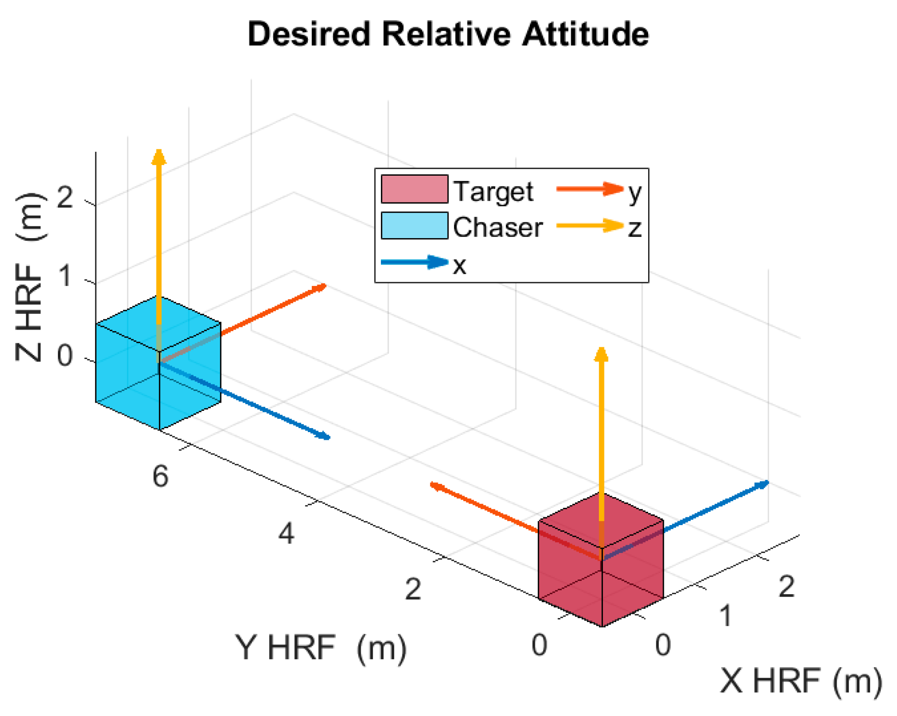
The desired relative attitude, defined in Section 3.2 and Section 4.2, corresponds to the following desired rotation matrix, illustrated in Figure 7,
R T R F d e s S C R F = 0 1 0 1 0 0 0 0 1
In this paper, Y TRF axis represents the approach axis of the target, as indicated in Table 7. Based on information of Table 7, and using the operating point defined in Section 4.2, the value of the nonlinear function ς evaluated at the reference point, reported in Equation (68), is equal to 06×1.
The stabilization thresholds, which are selected considering the performance of the G&C architecture, defined in Section 3.2.3, are reported in Table 10.
Figure 7. Desired Relative Attitude of the chaser with respect to the target. For simplicity of representation, the two satellites are represented as cubes.
Aerospace 12 00708 g007

6. Results

The statistical analysis on the results of the proposed G&C methodology is conducted across a set of 1000 simulations. The number of Monte Carlo simulations was empirically chosen to be sufficiently large to ensure convergence of the trajectory tracking error statistics. Table 11 outlines the parameters subjects to uncertainty according to a Gaussian distribution and the corresponding standard deviation. The uncertainties on knowledge about the initial relative position and velocity depend on the measurement errors of the LIDAR sensor, described in Table 3. Furthermore, the initial target attitude is randomized, and the initial angular velocity varies randomly between −1°/s and +1°/s around each axis.
All the simulations are run in MATLAB R2022b(×64) on Intel(R) Core(TM) i5-10210U CPU @ 1.60GHz and 16.0 GB of RAM.

6.1. Guidance Results

One of the random simulations is selected to discuss the results of the guidance algorithm. The user-defined parameters of the guidance function and tuning parameters of the SCP algorithms are shown in Table 12.
The starting point of the simulation is selected randomly in accordance with the procedure described in Table 11.
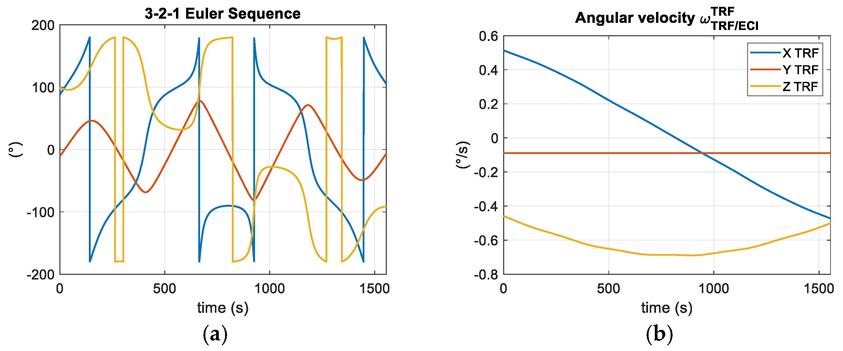
The time history of the relative attitude and angular velocity of the target throughout the entire simulation is shown in Figure 8. The target rotates around three axes according to its natural rotational dynamics. The angular velocity varies between −1°/s and 1°/s.
Figure 9 illustrates the nominal relative translational trajectory computed by the guidance function at Close-Range Rendezvous and Final Approach phases. In CR phase, the chaser moves from its starting position to the approach axis. In the Synchronization phase, the chaser approaches the target while synchronizing with its tumbling motion. The duration of this phase, calculated using the method described in Section 3.2.1, is equal to 440 s. At the end of Synchronization, the chaser is along the approach axis. In the subsequent Closing Phase, the chaser moves along this axis in order to reach the final desired position.
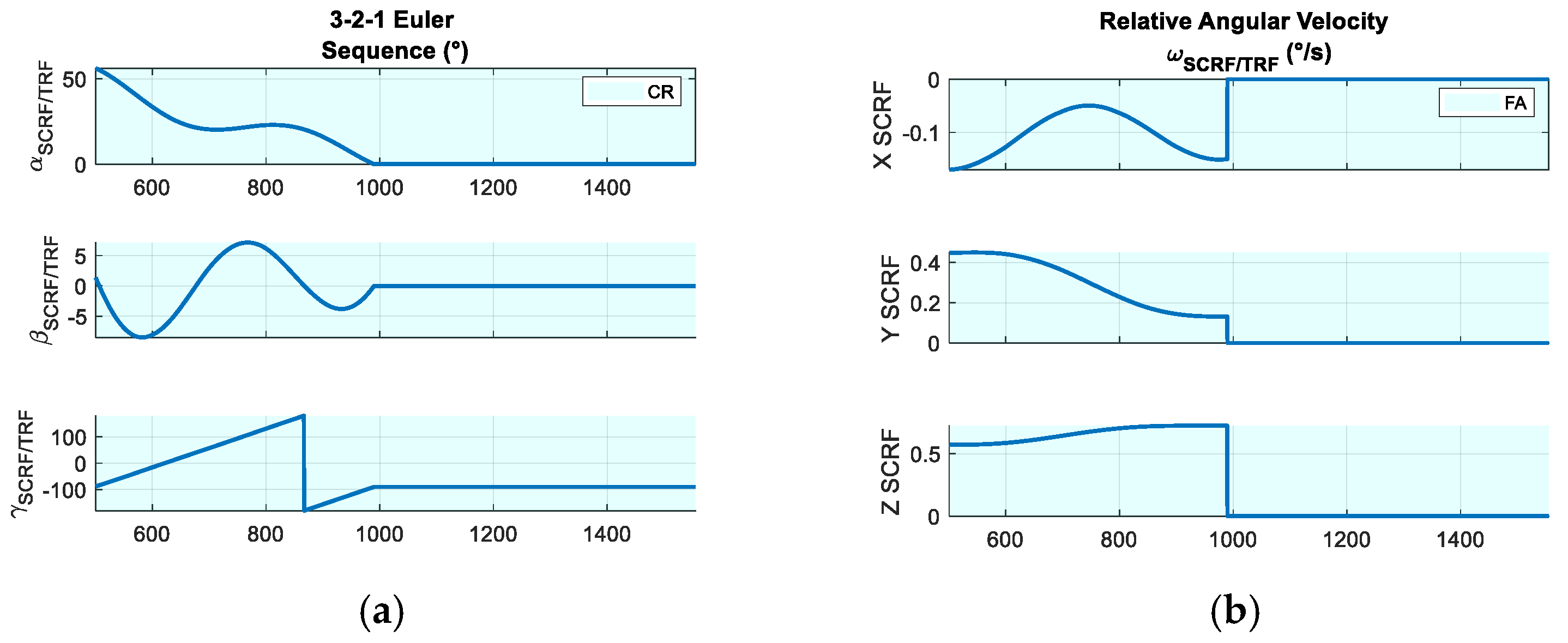
Regarding the rotational component, the Target Pointing Guidance output is discussed in the following Section. As explained in Section 3, the purpose of this function is to determine the misalignment between the LIDAR boresight axis and the LOS. Figure 10 illustrates the relative rotational trajectory in FA phase. During the Synchronization, the servicer satellite maneuvers to achieve the desired final relative attitude. Subsequently, once the synchronization with the tumbling motion of the target is achieved, the chaser maintains both the desired relative attitude and angular velocity.
Table 13, Table 14 and Table 15 outline the nominal linear velocities provided by the SCP algorithms for CR and FA phases, in contrast the nominal angular velocities are reported in Table 16. In the adopted semi-analytical approach, the largest nominal burns required to generate the initial guess are at the beginning and end of each phase, while the intermediate nominal burns are negligible or even null. When the initial guess is sufficiently accurate, the SCP algorithm is able to compute a nominal trajectory that satisfies the imposed path constraints with slight differences from the initial guess and, consequently, converge within few iterations. As a result, intermediate nominal burns remain negligible or null, as shown in Table 13 and Table 14. In contrast, Table 15 illustrates a different case in which the intermediate burns are not negligible. Here, the SCP algorithm must iteratively modify the reference trajectory obtained at the previous iteration to satisfy the path constraints, such as the docking cone, thrust region and actuator limitations. Following, the nominal trajectory is significantly different from the initial guess.
Figure 11 verifies that the KOZ constraint is satisfied throughout both phases, as the norm of the relative distance remains greater than the radius of the KOZ sphere. Similarly, during Synchronization in FA phase, the target visibility constraint is respected. Finally, the chaser relative trajectory remains within the docking cone during the last segment of FA phase, as expected.
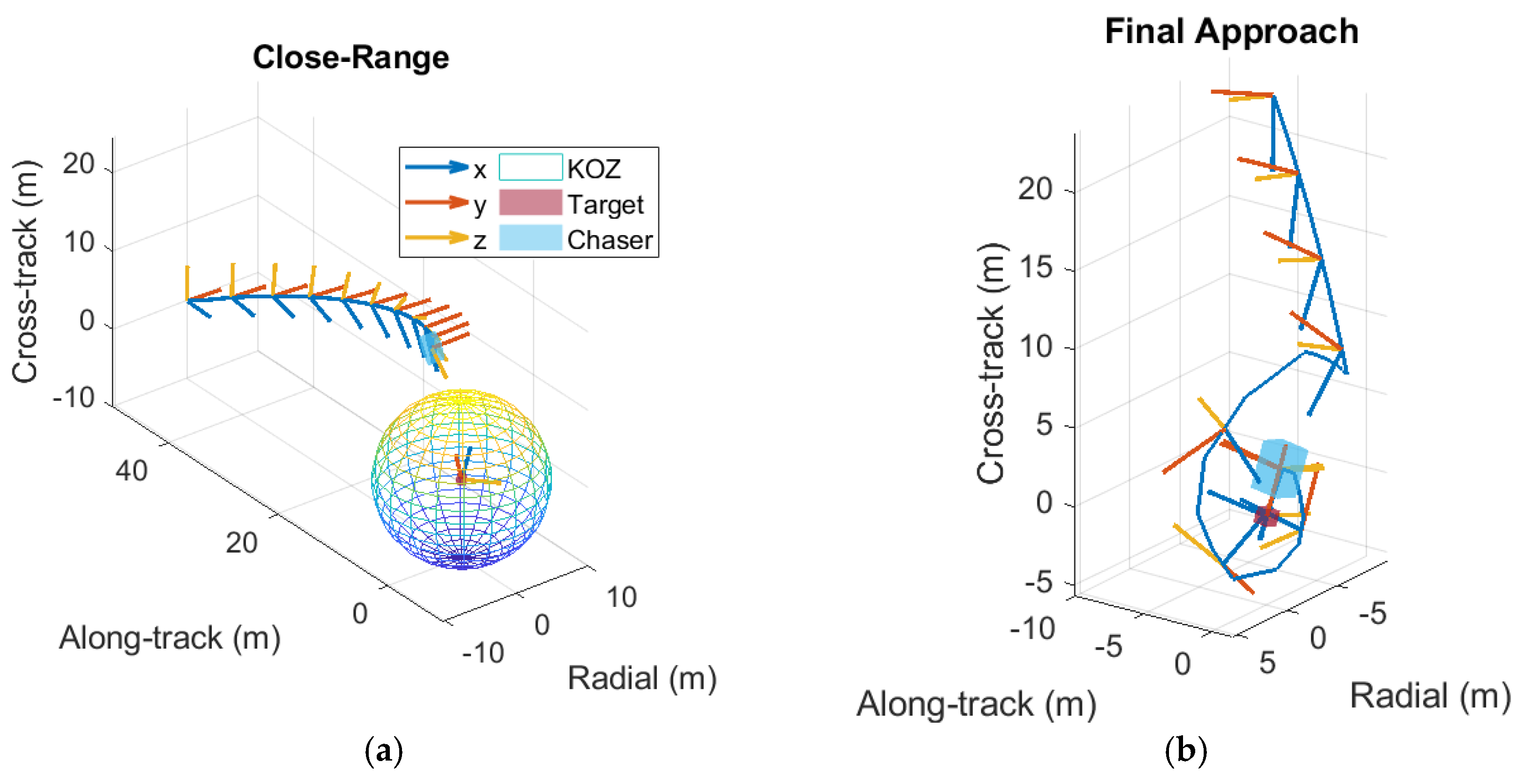
Figure 12 shows the 3D trajectory with respect to orbital frame. For clarity of representation, only the KOZ of the CR phase is represented. The relative attitude of the chaser is shown only along some points of trajectory. As clearly observed, at the end of the Rendezvous maneuver, the relative motion of the chaser is completely synchronized with the target’s tumbling motion.
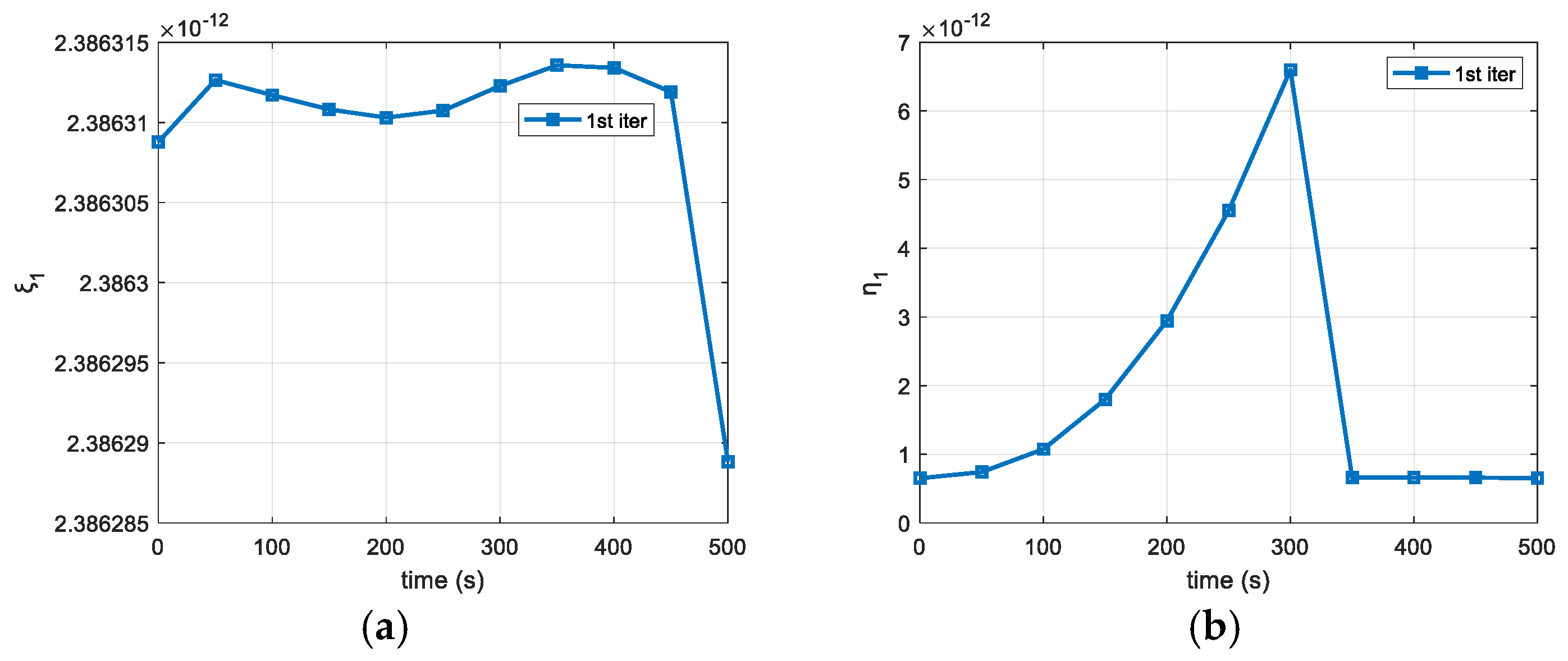
Figure 13 illustrates the optimization variables computed by the SCP algorithm during the Close-Range phase. In this case, the algorithm converges in a single iteration, highlighting the high efficiency of the initial guess, which already complies with the constraints. In contrast, during the Synchronization, the convergence of the roto-translational SCP algorithm is achieved within two iterations (Figure 14). Finally, during the last stage of the Final Approach phase, the SCP algorithm convergence requires 19 iterations (Figure 15). In this case, the initial guess does not verify the docking cone constraint. As a result, the translational trajectory is progressively modified at each iteration to satisfy this requirement, as evidenced by the continuous reduction of ξCONE,3.
A comparative analysis between the semi-analytical strategy adopted in this paper for generating the initial guess and a state-of-the-art polynomial interpolation-based approach is carried out within the same simulation environment, and the main differences are reported in Table 17. The resulting reference trajectories generated by SCP using the two initialization methods are similar. However, the proposed approach determines a solution characterized by a lower propellant consumption, while also allowing faster convergence, thereby reducing overall computational cost. In particular, during the Closing Phase, the number of iterations required by the SCP algorithm to converge reduces from 50 to 19. This improvement is attributed to the fact that the semi-analytical strategy provides an initial guess that is closer to the optimal solution to the original problem. As a result, convergence is accelerated once constraints are considered, while also improving performance in terms of fuel consumption. These results highlight the advantages of the proposed initialization strategy in improving efficiency and in supporting its adoption for onboard real-time applications.
Figure 15. (a) Trust region radius, η3, and virtual buffer, (b) ξKOZ,3 and (c) ξDOCK,3 in the last stage of Final Approach phase.
Aerospace 12 00708 g015

6.2. Control Results

This subsection describes controller’s performance for the simulation described in the previous subsection. The control errors are defined as the deviations between the current true state of the chaser and the nominal state provided by the guidance.
The weights of the translation H infinity controller (defined in Section 4.1) are listed in Table 18. The diagonal elements of matrix Wn are determined by the measurements errors introduced by the relative navigation system. These errors are assumed to be a white noise with 1 cm and 1 mm/s errors for relative position and velocity, respectively,
W n = 0.01 1 3 × 3 0 3 × 3 0 3 × 3 0.001 1 3 × 3 ,
The weight of actuators’ disturbances, Wd, is set to identity matrix, 13×3. In contrast, the weights of Quaternion Feedback Regulator [55],
K d = 0.5 I ^ c K p = 0.008 I ^ c K i = 0.0001 I ^ c ,
The weights of the Roto-translational H infinity controller (defined in Section 4.2) are listed in Table 19. The diagonal elements of matrix Wn contains also the measurement errors on the relative attitude and angular velocity components. Similarly, they are assumed to be a white noise with 0.1° (~1 × 10⁻³ in terms of Gibbs vector) and 0.01°/s errors for relative attitude and relative angular velocity, as outlined in [34].
W n = 0.01 1 3 × 3 0 3 × 3 0 3 × 3 0 3 × 3 0 3 × 3 0.001 1 3 × 3 0 3 × 3 0 3 × 3 0 3 × 3 0 3 × 3 0.001 1 3 × 3 0 3 × 3 0 3 × 3 0 3 × 3 0 3 × 3 0.01 π 180 1 3 × 3 ,
The matrix Wd,
W d = 1 3 × 3 0 3 × 3 0 1 1 1 0 1 1 1 0 1 3 × 3
The synthesis of the Translational and Roto-translational H infinity controller leads to a performance, γcontr,t and γcontr respectively, which represent the upper bound of the H infinity norm of the closed loop system, defined in Equation (52),
γcontr,t = 0.73,
γcontr = 0.68.
This indicates a good level of robustness of the system to external disturbances and uncertainties.
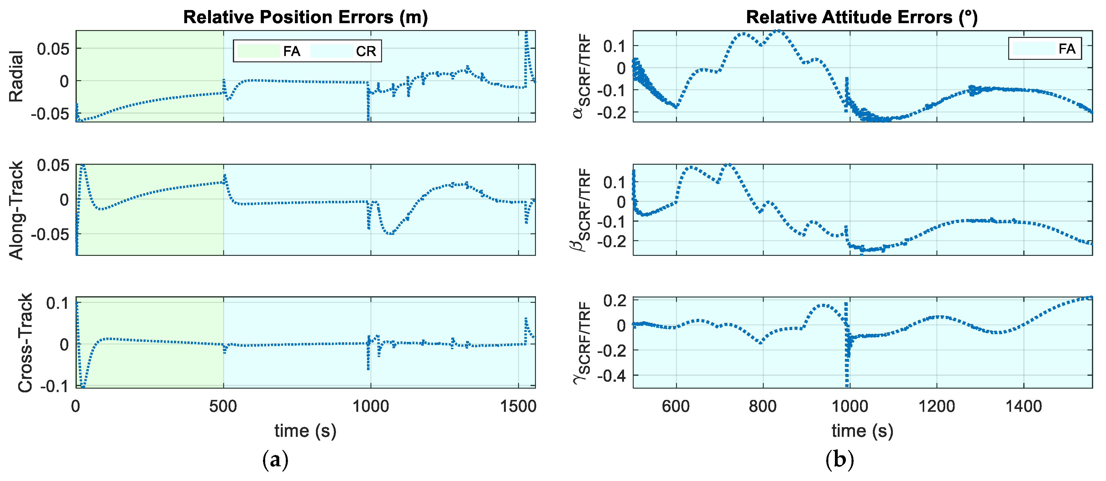
Figure 16 illustrates the Relative Position and Velocity control errors. The spikes in relative velocity plots are caused by nominal burns commanded by the guidance function. In fact, the actuation system executes these nominal burns gradually over multiple GNC cycles and not instantaneously. Similarly, this phenomenon produces spikes in the relative position. The maximum error is about 50 cm in cross track during the last burn of the Synchronization. However, these peaks highlight the controller’s robustness, since these discrepancies are corrected quickly when the nominal burn is completed. Particularly, a high accuracy can be observed in the vicinity of the docking point. In conclusion, the chaser is able to follow the reference relative trajectory.
The equivalent Euler angle is computed by the corresponding quaternion error δq provided by the Target Pointing Guidance. Figure 17 illustrates the time history of this equivalent Euler angle (θErrors) during the Close-Range phase, showing that the error in alignment with the LOS remains consistently below 3°. Analogously, the relative attitude (3-2-1 Euler Sequence) and angular velocity control errors during the Final Approach phase are also shown. Similarly to the translational case, some spikes occur in relative attitude and angular velocity during the execution of the nominal burns. However, these spikes are relatively small (maximum error less than 2° for each component) and quickly recovered by controller actions.
Table 20 outlines the statistical analysis of controller’s performance in terms of relative position and attitude errors.
The same simulation is repeated without the use of the dispatching function. In this case, the commanded actions computed by the H-infinity controller are directly applied to the servicer satellite. The resulting relative position and attitude control errors are shown in Figure 18. In this scenario, the controller demonstrates improved accuracy in correcting tracking errors. In fact, the position errors remain within the centimeter level, while attitude errors are on the order of 0.1 degrees. Table 21 presents a statistical analysis of the control errors in relative position and attitude, allowing a direct comparison with the realistic case (Table 20), where the dispatching logic is considered. As observed, accuracy improves significantly in the ideal case. In particular, the standard deviation of the position control error is reduced by approximately 60% across all components, with the maximum in cross-track decreasing from 48.0 cm to 11.0 cm. Similarly, attitude control errors are notable reduced, with standard deviation decreasing by about 70% across all components. For instance, the yaw angle shows a reduction in maximum error from 1.51° to 0.50°.
Furthermore, a complementary comparison is presented in Table 22, where the 1-norm of commanded force is reported. As expected, the scenario with ideal impulsive thrusters shows a lower force magnitude. Specifically, the X SCRF component is halved, and similar trends are observed in the Y and Z SCRF components, with force magnitudes decreasing by approximately 12% and 70%. This reduction is consistent with the smaller tracking errors observed.
In the realistic scenario, the limitations of the actuation system prevent the instantaneous execution of the commanded actions computed by the H infinity controller. Consequently, the controller generates larger control actions to compensate for the actuator limitations, which increases propellant consumption.
In conclusion, the spikes in control errors observed in Figure 16 and Figure 17, along with the worsening performance in terms of control accuracy, are mainly attributed to the limitations of the actuator system.

6.3. Statistical Analysis

This subsection outlines the results of the above-mentioned statistical analysis. Figure 19 and Figure 20 show the relative position and velocity errors, respectively, at the end of the simulation, while Figure 21 and Figure 22 illustrate the relative attitude and angular velocity control errors.
The controller exhibits strong robustness, even in the presence of environmental and simulation uncertainties and different tumbling conditions. In fact, in terms of position accuracy, both the radial and along-track components generally exhibit errors below 10 cm, with the along-track direction showing the lowest mean and standard deviation. Conversely, the cross-track component reaches a maximum value of approximately 16 cm. These results confirm the controller’s ability to accurately track the reference relative position, guiding the servicer satellite to the final docking point with high precision.
Relative velocity control exhibits a comparable level of performance, maintaining the errors below 1 cm/s, and generally within the 0–0.1 cm/s range. This level of accuracy confirms the system’s ability to reach the docking port safely, with slight velocity errors.
Finally, a similar performance is observed in rotational dynamics. Relative attitude errors remain predominantly within the 0–0.5° range and never exceeds 2°. Moreover, angular velocity errors are consistently on the order of 10−2 deg/s, underlining the controller’s ability to synchronize with the target’s tumbling motion.
In conclusion, this statistical analysis validates the robustness and precision of the proposed coupled orbit–attitude H infinity controller, which is able to achieve high accuracy in both translational and rotational components, although uncertainties in the chaser’s physical properties, actuator configurations and initial conditions. Furthermore, these results confirm the applicability of the proposed guidance function for generating the reference trajectory.

7. Conclusions

This paper presents a Guidance and Control architecture for Close-Range rendezvous and Final Approach of a chaser spacecraft with a non-cooperative and tumbling space target. The guidance strategy is based on Sequential Convex Programming, which solves an optimization problem accounting for propellant consumption, dynamic constraints, collision avoidance, and sensor limitations. A translational H infinity controller coupled with a Quaternion Feedback Regulator is employed during the Close-Range phase. In contrast in the Final Approach phase, the trajectory tracking is handled by a coupled orbit–attitude H infinity controller. The overall architecture is tested within a high-fidelity simulation environment. Robustness of the proposed architecture is validated through a statistical analysis of 1000 Monte Carlo simulations.
The results confirm the effectiveness of the guidance function in generating feasible reference trajectories under various initial conditions. Moreover, the semi-analytical strategy proposed for generating the initial guess required by the SCP algorithm produces a trajectory that is close to the optimal solution of the original optimization problem. As a consequence, the number of iterations required for convergence reduces, e.g., from 50 iterations when using a standard state-of-the-art polynomial interpolation to 19 during the final Closing Phase maneuver, and so does the computational cost. Additionally, this initial guess also enhances the optimality of the final solution, reducing nominal propellant consumption.
In addition, the robustness of the H infinity controller in managing both translational and rotational dynamics is observed. Small tracking errors across all state components are observed throughout the maneuvers. Spikes in both relative velocity and angular velocity are caused by nominal translational and rotational velocity increments, which are not applied instantaneously by the chaser’s actuation system. Similarly, this also leads to deviations in relative position and attitude. The resulting maximum errors are approximately 50 cm in the cross-track direction and less than 2° in relative attitude. However, once these nominal burns are completed, the discrepancies in both translational and rotational dynamics are rapidly compensated by the control actions (force and torque) generated by the H-infinity controller. As a result, position accuracy on the order of centimeters and attitude accuracy on the order of 0.1° are achieved near the docking point.
The statistical analysis shows that at the docking point the relative position and attitude errors remain below 10 cm and 1°, respectively, while the relative velocity errors are below 1 cm/s. In addition, the angular velocity errors are negligible, highlighting the system’s ability to synchronize with the target’s rotational motion. All these results are achieved despite considering several sources of uncertainty on the knowledge of the target and chaser physical and geometrical parameters.
Such performance demonstrates the capability of the proposed Guidance and Control system to guide the chaser to the docking point with high accuracy in relative position while ensuring a safe relative velocity, an essential condition for proximity operations. Furthermore, the system successfully synchronizes with the target’s tumbling motion, confirming its applicability for autonomous rendezvous involving non-cooperative targets.
Future works will include the implementation and testing of alternative Guidance and Control strategies, in order to quantitatively assess the potential advantages and limitations of the proposed approach compared to state-of-the-art techniques, such as Artificial Potential Functions for guidance tasks or SDRE-based methods for trajectory tracking.
In parallel, the real-time feasibility of the proposed strategy will be further investigated by implementing it on embedded processors. This will involve coding the G&C methodology on suitable hardware for space missions, followed by performance evaluation through Processor-in-the-Loop and Hardware-in-the-Loop tests. These steps will be essential to validate its applicability in autonomous rendezvous scenarios involving non-cooperative and tumbling space targets.

Author Contributions

Conceptualization, A.M., A.N. and R.O.; methodology, A.M., A.N. and R.O.; software, A.M., A.N. and G.N.; validation, A.M., A.N. and R.O.; formal analysis, A.M.; investigation, A.M.; resources, A.M.; data curation, A.M. and A.N.; writing—original draft preparation A.M.; writing—review and editing A.M., A.N. and R.O.; visualization A.M. and R.O.; supervision, A.N. and R.O.; project administration, G.F. and M.G. All authors have read and agreed to the published version of the manuscript.

Funding

This work was carried out within the Space It Up! project funded by the Italian Space Agency (ASI) and the Italian Ministry of University and Research (MUR) under contract No. 2024-5-E.0, CUP No. I53D24000060005.

Data Availability Statement

The data presented in this study are available on request from the corresponding author.

Conflicts of Interest

The authors declare no conflicts of interest.

Abbreviations

The following abbreviations are used in this manuscript:
IOSIn-Orbit Servicing
ADRActive Debris Removal
RPORendezvous and Proximity Operation
GNC Guidance, Navigation and Control
G&C Guidance and Control
DOF Degree of Freedom
APFArtificial Potential Function 
SCPSequential Convex Programming 
HJBHamilton–Jacobi–Bellman
SDREState-Dependent Riccati Equation
NMPC Nonlinear Model Predictive Control 
NNNeural Network
RBFNNRadial Basis Function Neural Network
EOElectro-Optical
QFRQuaternion Feedback Regulator 
MEKFMultiplicative Extended Kalman Filter 
FOVField of View 
CoGCentre of Gravity
SCRFSpacecraft Centred Reference Frame 
TRFTarget Reference Frame 
LRFLIDAR Reference Frame
HRFHill Reference Frame 
ECIEarth Centered Inertial Reference Frame
RVRendezvous 
CR Close-Range Rendezvous Phase
FA Final Approach Phase
KOZKeep-Out Zone
LOSLine of Sight
RCSReaction Control Systems
RWReaction Wheel
CWClohessy-Wiltshire

References

  1. Rybus, T.; Wojtunik, M.; Basmadji, F.L. Optimal Collision-Free Path Planning of a Free-Floating Space Robot Using Spline-Based Trajectories. Acta Astronaut. 2022, 190, 395–408. [Google Scholar] [CrossRef]
  2. Rousso, P.; Samsam, S.; Chhabra, R. A Mission Architecture for On-Orbit Servicing Industrialization. In Proceedings of the 2021 IEEE Aerospace Conference (50100), Big Sky, MT, USA, 6–13 March 2021; pp. 1–14. [Google Scholar]
  3. Ma, B.; Jiang, Z.; Liu, Y.; Xie, Z. Advances in Space Robots for On-Orbit Servicing: A Comprehensive Review. Adv. Intell. Syst. 2023, 5, 2200397. [Google Scholar] [CrossRef]
  4. Luo, Y.; Zhang, J.; Tang, G. Survey of Orbital Dynamics and Control of Space Rendezvous. Chin. J. Aeronaut. 2014, 27, 1–11. [Google Scholar] [CrossRef]
  5. Leomanni, M.; Quartullo, R.; Bianchini, G.; Garulli, A.; Giannitrapani, A. Variable-Horizon Guidance for Autonomous Rendezvous and Docking to a Tumbling Target. J. Guid. Control Dyn. 2022, 45, 846–858. [Google Scholar] [CrossRef]
  6. Chan, M.; Sargent, R. Rendezvous Approach Guidance for Uncooperative Tumbling Satellites. In Proceedings of the 2020 IEEE Aerospace Conference, Big Sky, MT, USA, 7–14 March 2020; pp. 1–17. [Google Scholar]
  7. Liu, J.; Li, H. Artificial Potential Function Safety and Obstacle Avoidance Guidance for Autonomous Rendezvous and Docking with Noncooperative Target. Math. Probl. Eng. 2019, 2019, 3451864. [Google Scholar] [CrossRef]
  8. Fehse, W. Automated Rendezvous and Docking of Spacecraft; Cambridge Aerospace Series; Cambridge University Press: Cambridge, NY, USA, 2003; ISBN 978-0-521-82492-7. [Google Scholar]
  9. Zhou, B.-Z.; Liu, X.-F.; Cai, G.-P. Motion-Planning and Pose-Tracking Based Rendezvous and Docking with a Tumbling Target. Adv. Space Res. 2020, 65, 1139–1157. [Google Scholar] [CrossRef]
  10. Liu, J.; Li, H.; Luo, Y.; Zhang, J. Robust Adaptive Relative Position and Attitude Integrated Control for Approaching Uncontrolled Tumbling Spacecraft. Proc. Inst. Mech. Eng. Part G J. Aerosp. Eng. 2020, 234, 361–374. [Google Scholar] [CrossRef]
  11. Boyarko, G.; Yakimenko, O.; Romano, M. Optimal Rendezvous Trajectories of a Controlled Spacecraft and a Tumbling Object. J. Guid. Control Dyn. 2011, 34, 1239–1252. [Google Scholar] [CrossRef]
  12. Ventura, J.; Ciarcià, M.; Romano, M.; Walter, U. Fast and Near-Optimal Guidance for Docking to Uncontrolled Spacecraft. J. Guid. Control Dyn. 2017, 40, 3138–3154. [Google Scholar] [CrossRef]
  13. Ge, J.; Zhao, J.; Yuan, J. A Novel Guidance Strategy for Autonomously Approaching a Tumbling Target. Proc. Inst. Mech. Eng. Part G J. Aerosp. Eng. 2018, 232, 861–871. [Google Scholar] [CrossRef]
  14. Zappulla, R.; Park, H.; Virgili-Llop, J.; Romano, M. Real-Time Autonomous Spacecraft Proximity Maneuvers and Docking Using an Adaptive Artificial Potential Field Approach. IEEE Trans. Contr. Syst. Technol. 2019, 27, 2598–2605. [Google Scholar] [CrossRef]
  15. Li, Q.; Yuan, J.; Zhang, B.; Wang, H. Disturbance Observer Based Control for Spacecraft Proximity Operations with Path Constraint. Aerosp. Sci. Technol. 2018, 79, 154–163. [Google Scholar] [CrossRef]
  16. Lopez, I.; Mclnnes, C.R. Autonomous Rendezvous Using Artificial Potential Function Guidance. J. Guid. Control Dyn. 1995, 18, 237–241. [Google Scholar] [CrossRef]
  17. Malyuta, D.; Reynolds, T.P.; Szmuk, M.; Lew, T.; Bonalli, R.; Pavone, M.; Açıkmeşe, B. Convex Optimization for Trajectory Generation: A Tutorial on Generating Dynamically Feasible Trajectories Reliably and Efficiently. IEEE Control Syst. 2022, 42, 40–113. [Google Scholar] [CrossRef]
  18. Zhang, Y.; Zhu, B.; Cheng, M.; Li, S. Trajectory Optimization for Spacecraft Autonomous Rendezvous and Docking with Compound State-Triggered Constraints. Aerosp. Sci. Technol. 2022, 127, 107733. [Google Scholar] [CrossRef]
  19. Patterson, M.A.; Rao, A.V. GPOPS-II: A MATLAB Software for Solving Multiple-Phase Optimal Control Problems Using Hp-Adaptive Gaussian Quadrature Collocation Methods and Sparse Nonlinear Programming. ACM Trans. Math. Softw. 2014, 41, 1–37. [Google Scholar] [CrossRef]
  20. Haolong, W.; Haoping, S. Online Trajectory Planning for Docking to Tumbling Spacecraft with Active Maneuver. In Proceedings of the 2021 33rd Chinese Control and Decision Conference (CCDC), Kunming, China, 22–24 May 2021; pp. 6981–6986. [Google Scholar]
  21. Wang, J.-Y.; Liang, H.-Z.; Sun, Z.-W.; Wu, S.-N.; Zhang, S.-J. Relative Motion Coupled Control Based on Dual Quaternion. Aerosp. Sci. Technol. 2013, 25, 102–113. [Google Scholar] [CrossRef]
  22. Xin, M.; Pan, H. Nonlinear Optimal Control of Spacecraft Approaching a Tumbling Target. Aerosp. Sci. Technol. 2011, 15, 79–89. [Google Scholar] [CrossRef]
  23. Lee, D.; Bang, H. Robust Nonlinear Full State Feedback Control for Autonomous Close Range Rendezvous and Docking of Spacecraft. System 2013, 3, 544–557. [Google Scholar]
  24. Akhloumadi, M.; Ivanov, D. Influence of Satellite Motion Control System Parameters on Performance of Space Debris Capturing. Aerospace 2020, 7, 160. [Google Scholar] [CrossRef]
  25. Malladi, B.P.; Di Cairano, S.; Weiss, A. Nonlinear Model Predictive Control of Coupled Rotational-Translational Spacecraft Relative Motion. In Proceedings of the 2019 American Control Conference (ACC), Philadelphia, PA, USA, 10–12 July 2019; pp. 3581–3586. [Google Scholar]
  26. Kasiri, A.; Fani Saberi, F. Coupled Position and Attitude Control of a Servicer Spacecraft in Rendezvous with an Orbiting Target. Sci. Rep. 2023, 13, 4182. [Google Scholar] [CrossRef]
  27. Ulrich, S.; Hayhurst, D.L.; Saenz Otero, A.; Miller, D.; Barkana, I. Simple Adaptive Control for Spacecraft Proximity Operations. In Proceedings of the AIAA Guidance, Navigation, and Control Conference, National Harbor, MD, USA, 13–17 January 2014. [Google Scholar]
  28. Autenrieb, J.; Annaswamy, A.M. Safe and Stable Adaptive Control for a Class of Dynamic Systems. In Proceedings of the 2023 62nd IEEE Conference on Decision and Control (CDC), Singapore, 13–15 December 2023. [Google Scholar]
  29. Xia, K.; Lee, T.; Park, S.-Y. Adaptive Saturated Neural Network Tracking Control of Spacecraft: Theory and Experimentation. Int. J. Aerosp. Eng. 2019, 2019, 7687459. [Google Scholar] [CrossRef]
  30. Xia, K.; Huo, W. Robust Adaptive Backstepping Neural Networks Control for Spacecraft Rendezvous and Docking with Input Saturation. ISA Trans. 2016, 62, 249–257. [Google Scholar] [CrossRef]
  31. Liu, Q.; Li, D.; Ge, S.S.; Ouyang, Z. Adaptive Feedforward Neural Network Control with an Optimized Hidden Node Distribution. IEEE Trans. Artif. Intell. 2021, 2, 71–82. [Google Scholar] [CrossRef]
  32. Wei, C.; Chen, Q.; Liu, J.; Yin, Z.; Luo, J. An Overview of Prescribed Performance Control and Its Application to Spacecraft Attitude System. Proc. Inst. Mech. Eng. Part I J. Syst. Control Eng. 2021, 235, 435–447. [Google Scholar] [CrossRef]
  33. Zames, G. Feedback and Optimal Sensitivity: Model Reference Transformations, Multiplicative Seminorms, and Approximate Inverses. IEEE Trans. Automat. Contr. 1981, 26, 301–320. [Google Scholar] [CrossRef]
  34. Pirat, C.; Ankersen, F.; Walker, R.; Gass, V. H and μ-Synthesis for Nanosatellites Rendezvous and Docking. IEEE Trans. Contr. Syst. Technol. 2020, 28, 1050–1057. [Google Scholar] [CrossRef]
  35. Diab, A.A.Z.; El-Sayed, A.-H.M.; Abbas, H.H.; Sattar, M.A.E. Robust Speed Controller Design Using H_infinity Theory for High-Performance Sensorless Induction Motor Drives. Energies 2019, 12, 961. [Google Scholar] [CrossRef]
  36. Bansal, A.; Sharma, V. Design and analysis of robust H-infinity controller. Control Theory Inform. 2013, 3, 7–14. [Google Scholar]
  37. Jung, K.-W.; Lee, S.-D.; Jung, C.-G.; Lee, C.-H. Model Predictive Guidance for Fuel-Optimal Landing of Reusable Launch Vehicles. arXiv 2024. [Google Scholar] [CrossRef]
  38. Kumagai, N.; Oguri, K. Adaptive-Mesh Sequential Convex Programming for Space Trajectory Optimization. J. Guid. Control Dyn. 2024, 47, 2213–2220. [Google Scholar] [CrossRef]
  39. Zhou, D.; Zhang, Y.; Li, S. Receding Horizon Guidance and Control Using Sequential Convex Programming for Spacecraft 6-DOF Close Proximity. Aerosp. Sci. Technol. 2019, 87, 459–477. [Google Scholar] [CrossRef]
  40. Zhang, Y.; Cheng, M.; Nan, B.; Li, S. Stochastic Trajectory Optimization for 6-DOF Spacecraft Autonomous Rendezvous and Docking with Nonlinear Chance Constraints. Acta Astronaut. 2023, 208, 62–73. [Google Scholar] [CrossRef]
  41. Wie, B. Space Vehicle Dynamics and Control, 2nd ed.; American Institute of Aeronautics and Astronautics: Reston, VA, USA, 2008; ISBN 978-1-56347-953-3. [Google Scholar]
  42. Nocerino, A.; Opromolla, R.; Fasano, G.; Grassi, M. LIDAR Adaptive Parameters Selection and Target Pointing Control for Close-Proximity Space Operations. Aerosp. Sci. Technol. 2024, 155, 109646. [Google Scholar] [CrossRef]
  43. Melton, R.G. Time-Explicit Representation of Relative Motion Between Elliptical Orbits. J. Guid. Control Dyn. 2000, 23, 604–610. [Google Scholar] [CrossRef]
  44. Zhao, S. Time Derivative of Rotation Matrices: A Tutorial. arXiv 2016. [Google Scholar] [CrossRef]
  45. Lovell, T.A.; Spencer, D.A. Relative Orbital Elements Formulation Based upon the Clohessy-Wiltshire Equations. J. Astronaut. Sci. 2014, 61, 341–366. [Google Scholar] [CrossRef]
  46. Ankersen, F. Guidance, Navigation, Control and Relative Dynamics for Spacecraft Proximity Maneuvers. Ph.D. Thesis, Aalborg University, Aalborg, Denmark, 2011. [Google Scholar]
  47. Kristiansen, R.; Grøtli, E.I.; Nicklasson, P.J.; Gravdahl, J.T. A Model of Relative Translation and Rotation in Leader-Follower Spacecraft Formations. MIC 2007, 28, 3–14. [Google Scholar] [CrossRef]
  48. Proakis, J.G.; Manolakis, D.G. Digital Signal Processing: Principles, Algorithms, and Applications, 3rd ed.; Prentice Hall: Upper Saddle River, NJ, USA, 1996; ISBN 978-0-13-373762-2. [Google Scholar]
  49. Opromolla, R.; Fasano, G.; Rufino, G.; Grassi, M. Pose Estimation for Spacecraft Relative Navigation Using Model-Based Algorithms. IEEE Trans. Aerosp. Electron. Syst. 2017, 53, 431–447. [Google Scholar] [CrossRef]
  50. Nocerino, A.; Vela, C.; Fasano, G.; Grassi, M.; Opromolla, R. Navigation-Aware Waypoint-Based Guidance and Control for Spacecraft Close-Proximity Operations. In Proceedings of the AIAA SCITECH 2025 Forum, Orlando, FL, USA, 6–10 January 2025. [Google Scholar]
  51. Opromolla, R.; Nocerino, A. Uncooperative Spacecraft Relative Navigation With LIDAR-Based Unscented Kalman Filter. IEEE Access 2019, 7, 180012–180026. [Google Scholar] [CrossRef]
  52. Lawson, C.L.; Hanson, R.J. Solving Least Squares Problems; Society for Industrial and Applied Mathematics: Philadelphia, PA, USA, 1995; ISBN 978-0-89871-356-5. [Google Scholar]
  53. Sidi, M.J. Spacecraft Dynamics and Control: A Practical Engineering Approach, 1st ed.; Cambridge University Press: Cambridge, UK, 1997; ISBN 978-0-521-55072-7. [Google Scholar]
  54. Bialke, B. High Fidelity Mathematical Modeling of Reaction Wheel Performance. In Advances in the Astronautical Sciences; Univelt, Inc.: San Diego, CA, USA, 1998; Volume 98, pp. 483–496. [Google Scholar]
  55. La Marca, T.A.; Nocerino, A.; Opromolla, R.; Grassi, M. Robust Attitude Control for Space Target Pointing in Proximity Operations. In Proceedings of the IAF Astrodynamics Symposium, Milan, Italy, 14–18 October 2024; International Astronautical Federation (IAF): Milan, Italy, 2024; pp. 1524–1536. [Google Scholar]
Figure 1. A 2D representation of the considered rendezvous scenario: Close-Range Rendezvous and Final Approach phases.
Aerospace 12 00708 g001
Figure 2. Schematic representation of Guidance, Navigation and Control architecture for the Close-Range phase. The blue blocks indicate the original functions proposed in this paper and described in the following.
Aerospace 12 00708 g002
Figure 3. Schematic representation of Guidance, Navigation and Control architecture for the Final Approach phase. The blue blocks indicate the original functions proposed in this paper and described in the following.
Aerospace 12 00708 g003
Figure 4. Guidance functions implemented during the Synchronization Phase.
Aerospace 12 00708 g004
Figure 5. Block diagram of a generic mixed sensitivity H infinity controller [34].
Aerospace 12 00708 g005
Figure 6. Block diagram of the simulation environment. The blue blocks represent the sensors and actuators, the green block corresponds to the numerical propagator, and the violet blocks indicate the functional components.
Aerospace 12 00708 g006
Figure 8. (a) Time history of the relative attitude of the target with respect to HRF. To better understand the relative attitude variations, a 3-2-1 Euler Sequence representation is chosen: blue represents the first rotation, (αTRF/HRF); red the second (βTRF/HRF) and yellow the third rotation (γTRF/HRF). (b) Time history of the target angular velocity.
Aerospace 12 00708 g008
Figure 9. Nominal Translation Trajectory: (a) Relative Position expressed in HRF and (b) Relative Velocity expressed in HRF and (c) Relative Position expressed in TRF.
Aerospace 12 00708 g009
Figure 10. Nominal Rotational Trajectory: (a) Relative Attitude of the chaser with respect to the target (3-2-1 Euler Sequence) and (b) Relative Angular Velocity expressed in SCRF.
Aerospace 12 00708 g010
Figure 11. Constraints: (a) KOZ, (b) Target Visibility and (c) Docking Cone.
Aerospace 12 00708 g011
Figure 12. The 3D planned trajectory: (a) Close-Range and (b) Final Approach phase. The x axis of the chaser also denotes the boresight axis of the LIDAR.
Aerospace 12 00708 g012
Figure 13. (a) Trust region radius, η1, and (b) virtual buffer, ξ1 in Close-Range phase.
Aerospace 12 00708 g013
Figure 14. (a) Trust region radius, η2, and virtual buffer, (b) ξKOZ,2 and (c) ξFOV,2 in the first segment of Final Approach phase.
Aerospace 12 00708 g014
Figure 16. Translational Control Errors: (a) Relative Position; (b) Relative Velocity.
Aerospace 12 00708 g016
Figure 17. Rotational Control Errors: (a) Equivalent Euler Angle which corresponds to the rotation quaternion δq, during the Close-Range phase; (b) Relative Attitude (3-2-1 Euler Sequence) and (c) Relative Angular Velocity during the Final Approach phase.
Aerospace 12 00708 g017
Figure 18. Control Errors: (a) Relative Position; (b) Relative Attitude. The simulation is performed without the application of the dispatching function.
Aerospace 12 00708 g018
Figure 19. Distribution of the Relative Position Control Errors at the end of the simulation: (a) Radial component; (b) Along-Track component; (c) Cross-Track component.
Aerospace 12 00708 g019
Figure 20. Distribution of the Relative Velocity Control Errors at the end of the simulation: (a) Radial component; (b) Along-Track component; (c) Cross-Track component.
Aerospace 12 00708 g020
Figure 21. Distribution of the Relative Attitude Errors at the end of the simulation: (3-2-1 Euler Angles): (a) αTRF/HRF; (b) βTRF/HRF; (c) γTRF/HRF.
Aerospace 12 00708 g021
Figure 22. Distribution of the Relative Angular Velocity Errors at the end of the simulation: (a) X SCRF component; (b) Y SCRF component; (c) Z SCRF component.
Aerospace 12 00708 g022
Table 1. Parameters for numerical propagation of orbital and rotational dynamics.
ParameterValue
GravityModelEGM2008
Maximum degree70
Maximum order70
Third-body perturbationsIncluded effectsSun—Moon
Atmospheric dragModelNRLMSISE00
Drag Coefficient2.0
Solar radiationSolar radiation pressure4.57 × 10−6 N/m2
Reflective coefficient1.0
Table 6. Chaser spacecraft characteristics.
ParameterValue
Inertia matrix Ic (kgm2) 2000 0 0 0 4500 0 0 0 3000
Mass (kg)2000
L × W × H (m)3 × 2 × 2
FOV/2 (°)20 
Δvmax (m/s)0.165
Δωmax (°/s)3.15
b [1 0 0]T
r SCRF LRF SCRF (m)[1.5 0 0]T
Table 7. Target spacecraft characteristics.
ParameterValue
Inertia matrix, It, (kgm2) 300 0 0 0 100 0 0 0 300
Mass (kg)380
L × W × H (m)1 × 1 × 1
Table 8. Simulation characteristics.
ParameterValue
Semi-major axis (km)6928
Eccentricity0.002
Orbit inclination (°)5.20
Right Ascension of the Ascending Node (°)0
Argument of perigee (°)0
True Anomaly (°)0
Orbital Period (s)5711.8
Table 9. Initial nominal conditions of the simulation.
ParameterValue
Initial   relative   distance ,   r TRF SCRF HRF (m)[0 50 0]T
Initial   relative   velocity ,   v SCRF / TRF HRF (m)[0 0 0]T
Initial   attitude   with   respect   to   HRF ,   q SCRF / HRF [0 0 −0.71 0.71]T
Initial   absolute   attitude ,   q SCRF / ECI [0.032 0.032 −0.71 0.71]T
Initial   angular   velocity ,   ω SCRF / ECI S C R F (°/s)[0 0 0.063]T
Table 10. Stabilization Thresholds.
ThresholdValue
Relative Position (m)0.025
Relative Velocity (m/s)0.01
Relative Attitude (°)2.0
Relative Angular Velocity (°/s)0.5 
Stabilization Threshold Duration (s)30
Table 11. Statistical Values of the initial conditions.
UncertaintiesValue (3σ)
Initial Misalignment of the LIDAR boresight (°)5
Knowledge of the Initial Relative Position (cm)25
Knowledge of the Initial Relative Velocity (cm/s)2
Knowledge of the Chaser mass (%)5
Knowledge of the Chaser inertia (%)5
RCS misalignment (°)0.01
RCS displacement (mm)5
Knowledge of Chaser’s CoG (mm)5
RWs misalignment (°)0.01
RCS displacement (mm)5
Knowledge of the target inertia (%)5
Table 12. User-defined parameters of the guidance function including SCP implementation.
Parameter Value
d1, d2, d3 (m)25, 10, 3
r A P P [0 1 0]T
r TRF APP TRF (m)[0 3 0]T
αcone (°)15
KOZ radius, r1, r2, r3 (m)10, 10, 2
t1, t3 (s)500, 500
N1, N2, N310, 5, 10
φdes (°)30
t2,max, t2,min, t2,pred (s)2000, 100, 2000
wη,1, wη,2, wη,3500, 100, 100
wξ,1, wξ,2, wξ,3100, 1000, 1000
εx, εJ5 × 10−4
Table 13. Nominal Linear Velocities in Close-Range Phase.
ΔV (cm/s)Close Range
1st2nd3rd4th5th6th7th8th9th10th11th
Radial4.10.00.00.00.00.00.00.00.00.07.8
Along-Track−10.30.00.00.00.00.00.00.00.00.09.1
Cross-Track3.50.00.00.00.00.00.00.00.00.0−4.1
Table 14. Nominal Linear Velocities in Synchronization segment of Final Approach Phase.
ΔV (cm/s)Synchronization Phase
1st2nd3rd4th5th6th
Radial−0.10.00.00.00.07.9
Along-Track1.70.00.00.00.0−2.4
Cross-Track2.70.00.00.00.012.2
Table 15. Nominal Linear Velocities in Closing segment of Final Approach Phase.
ΔV (cm/s)Closing Phase
1st2nd3rd4th5th6th7th8th9th10th11th
Radial−1.5−3.1−4.9−3.2−1.7−0.81.81.70.60.61.5
Along-Track0.80.91.71.10.11.4−1.6−1.3−0.5−0.5−1.4
Cross-Track−7.6−3.1−0.71.91.33.73.20.0−0.30.0−0.8
Table 16. Nominal Angular Velocities in Synchronization segment of Final Approach Phase.
Δω (°/s)Synchronization Phase
1st2nd3rd4th5th6th
X SCRF0.000−0.001−0.001−0.001−0.0010.149
Y SCRF−0.003−0.006−0.006−0.006−0.007−0.127
Z SCRF0.0040.0030.0020.0020.000−0.720
Table 17. Comparison between the reference trajectories obtained with the two initialization methods: number of SCP iterations until convergence and propellant consumption.
Maneuver PhaseInitial Guess Methodology
Semi-Analytical ApproachPolynomial Interpolation
Iterations Δ V 2 (cm/s)Iterations Δ V 2 (cm/s)
Close-Range124.3335.3
Synchronization217.9218.6
Closing1937.85054.0
Table 18. Parameters A1,i, M1,i, ω1,i, A2,i, M2,i, ω2,i, A3,i, M3,i, and ω3,i (Translational H infinity Controller).
Weights Value Weights Value Weights Value
A1,i0.01A2,i1000A3,i0.05
M1,i1.8M2,i10M3,i10
ω1,i
(rad/s)
0.01ω2,i
(rad/s)
0.05ω3,i
(rad/s)
0.05
Table 19. Parameters A1,i, M1,i, ω1,i, A2,i, M2,i, ω2,i, A3,i, M3,i, and ω3,i (Roto-translational H infinity Controller).
WeightsValueWeightsValueWeightsValue
A1,i0.01A2,i i = 1, …, 6100A3,i0.01
A2,i i = 7, …, 121000
M1,i1.8M2,i10M3,i10
ω1,i
(rad/s)
0.04ω2,i
(rad/s)
0.40ω3,i
(rad/s)
0.40
Table 20. Standard deviation (σ), mean value (μ) and maximum value (Max) of the Relative Position and Attitude Control errors over the entire simulation.
PositionσμMaxAttitude σμMax
Radial (cm)4.0−1.633.8αSCRF/TRF (°)0.39−0.151.30
Along-Track (cm)4.8−0.135.8βSCRF/TRF (°)0.35−0.111.12
Cross-Track (cm)4.7−0.448.0γSCRF/TRF (°)0.380.101.51
Table 21. Standard deviation (σ), mean value (μ) and maximum value (Max) of the Relative Position and Attitude Control errors over the entire simulation in the idea case.
Position σμMaxAttitude σμMax
Radial (cm)1.9−1.27.7αSCRF/TRF (°)0.11−0.080.25
Along-Track (cm)1.70.08.1βSCRF/TRF (°)0.12−0.090.27
Cross-Track (cm)1.50.011.0γSCRF/TRF (°)0.080.010.50
Table 22. Comparison of 1-norm of the commanded force components computed by the H infinity controller in the two scenarios.
Realistic ActuatorsImpulsive Actuators
ComponentValue ComponentValue
X SCRF (N)13,752.9X SCRF (N)7858.8
Y SCRF (N)5154.0Y SCRF (N)4521.6
Z SCRF (N)9476.0Z SCRF (N)2655.9
Disclaimer/Publisher’s Note: The statements, opinions and data contained in all publications are solely those of the individual author(s) and contributor(s) and not of MDPI and/or the editor(s). MDPI and/or the editor(s) disclaim responsibility for any injury to people or property resulting from any ideas, methods, instructions or products referred to in the content.