Article

Development and Evaluation of a Two-Dimensional Extension/Contraction-Driven Rover for Sideslip Suppression During Slope Traversal

1
Systems Engineering and Science, Graduate School of Engineering and Science, Shibaura Institute of Technology, Saitama 337-8570, Japan
2
Department of Mechanical & Electrical Engineering, Faculty of Engineering, Suwa University of Science, Nagano 391-0292, Japan
3
Department of Machinery and Control Systems, College of Systems Engineering and Science, Shibaura Institute of Technology, Saitama 337-8570, Japan
*
Author to whom correspondence should be addressed.
Aerospace 2025, 12(8), 699; https://doi.org/10.3390/aerospace12080699
Submission received: 30 June 2025 / Revised: 30 July 2025 / Accepted: 4 August 2025 / Published: 6 August 2025

Abstract

Wheeled rovers are widely used in lunar and planetary exploration missions owing to their mechanical simplicity and energy efficiency. However, they face serious mobility challenges on sloped soft terrain, especially in terms of sideslip and loss of attitude angle when traversing across slopes. Previous research proposed using wheelbase extension/contraction and intentionally sinking wheels into the ground, thereby increasing shear resistance and reducing sideslip. Building upon this concept, this study proposes a novel recovery method that integrates beam extension/contraction and Archimedean screw-shaped wheels to enable lateral movement without rotating the rover body. The beam mechanism allows for independent wheel movement, maintaining stability by anchoring stationary wheels during recovery. Meanwhile, the helical structure of the screw wheels helps reduce lateral earth pressure by scraping soil away from the sides, improving lateral drivability. Driving experiments on a sloped sandbox test bed confirmed that the proposed 2DPPL (two-dimensional push-pull locomotion) method significantly reduces sideslip and prevents a drop in attitude angle during slope traversal.

1. Introduction

The purposes of lunar and planetary exploration are to develop new technologies, expand the area of human activity, and elucidate the origins of the universe and life. In 2019, the National Aeronautics and Space Administration (NASA) proposed the Artemis program, which aims to achieve sustainable human activity and install the Lunar Gateway [1]. Consistent with this, space development has been promoted by many countries, and lunar and planetary exploration is attracting global attention. For example, the Japan Aerospace Exploration Agency (JAXA)s lander Smart Lander for Investigating Moon (SLIM) succeeded in a soft landing on the moon using a pinpoint landing technique, which keeps the landing error within 100 m of the target [2]. Furthermore, the Martian Moons eXploration (MMX) mission, scheduled to launch in 2026, aims to be a sample return from the Martian moon Phobos and is expected to reveal its origin [3]. On the other hand, NASAs Mars rover Perseverance has been exploring the Martian surface and has greatly contributed to understanding the origin of life, for example, by identifying traces suggesting the past existence of life [4].
Organizations have often used rovers to perform geological observations and collect soil data. In addition, rovers are also effective for transporting construction materials and tools. Researchers typically classify mobility systems into three main types: wheeled, crawler, and legged. Owing to a simple mechanism, they have adopted the wheeled-type rover. The crawler type has a large ground contact area and is well suited for traversing slopes; however, granular materials called regolith can become lodged in the chains and sprockets, leading to mechanical failure. The legged type provides stability and can travel while avoiding uneven surfaces and obstacles, but it has control difficulties regarding movement on soft terrain and the danger of making it impossible to continue exploration once it falls over. For these reasons, most planetary exploration rovers to date have adopted wheeled systems with a simple mechanism. However, wheeled-type rovers often experienced low mobility performance on soft terrain. The lunar surface is covered with regolith and is characterized by steep hills and craters. In such environments, wheels may slip or sink, causing the rover to become stuck. Additionally, when traversing slopes, sideslips may occur, in which the rover unintentionally slides downhill. These issues can lead to mission failure. For example, NASAs Mars rover Opportunity was found to have avoided entering a crater with steep inclines by analyzing its travel route [5]. This travelling leads to the reduction of exploration areas and longer exploration paths. Therefore, the development of traversal techniques for steep slopes is essential for expanding the reachable exploration area and improving mission efficiency.
To improve the mobility performance of wheeled rovers, a wide range of studies have been conducted. For example, Scrab and Sherpa have improved their mobility by adding new functions to their conventional driving mechanisms [6,7]. In addition to normal driving, they can perform discrete movements by extending or contracting their wheelbase using joint actuators, as shown in Figure 1. By alternately fixing the front or rear wheels and driving the other, the rover moves forward through wheelbase contraction and extension, gaining greater ground reaction force and improved mobility. This movement resembles that of an inchworm and is called push-pull locomotion (PPL) in this paper.
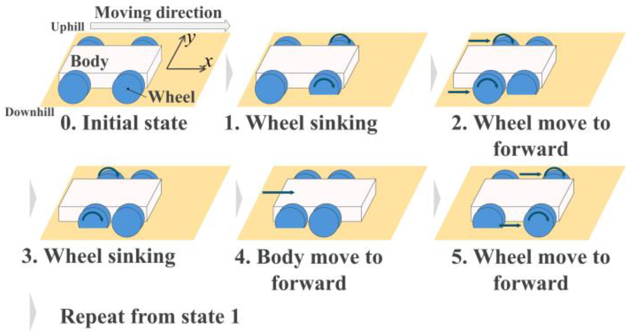
In our research group, we analyzed the relationship between wheel sinkage and resistance force, as well as the mechanism of traction force generation in a PPL-type rover. Based on this, we proposed Advanced Push-Pull Locomotion (APPL), which incorporates intentional wheel sinkage through wheel spinning into the PPL mechanism. This increases the contact area with the ground and enhances resistance force, enabling greater traction during wheelbase extension and retraction. APPL has been shown to improve slope climbing ability [8]. Figure 2 shows the APPL method. To further enhance slope traversal, 4-Wheel APPL (4WAPPL) was proposed, allowing each wheel to move independently while the others remain stationary. By enabling independent wheel motion, 4WAPPL increases the resistance force achieved with the APPL method [9]. The sequence of 4WAPPL is shown in Figure 3.
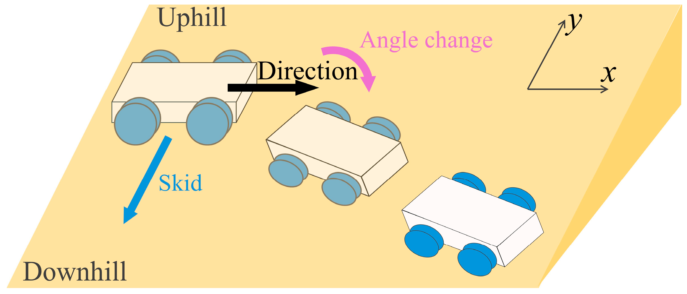
When a wheeled rover traverses a slope, as shown in Figure 4, sideslip could occur. The primary causes of this are ground collapse and a loss of attitude angle. First, the ground around the wheels could collapse while driving, preventing the wheels from obtaining sufficient resistance force, which causes the entire rover to slip down toward the valley side of the slope. In addition, due to gravity, the rover’s attitude angle gradually shifts toward the valley side. This not only increases the risk of the rover tipping over but also leads to deviation from the intended path. To address these issues, previous studies have proposed sideslip prevention methods using APPL or 4WAPPL. For example, one approach directs the driving force toward the uphill side by adjusting the steering angle and utilizing a high-slip state of the wheels [10]. These methods inhibit sideslip and attitude angle change by increasing the wheel sinkage or by redirecting the total driving force vector of the wheels. While the Push-Pull Locomotion method has demonstrated effectiveness in reducing the risk of sideslip during slope traversal, prior studies have predominantly focused on the prevention of sideslip. In contrast, recovery methods to restore the rover’s attitude or trajectory after sideslip has already occurred have not been sufficiently explored. Given that complete prevention of sideslip is often impractical in real-world environments, especially on steep or deformable terrain, the development of recovery mechanisms after sideslip is essential to enhance the robustness and reliability of rover mobility systems.
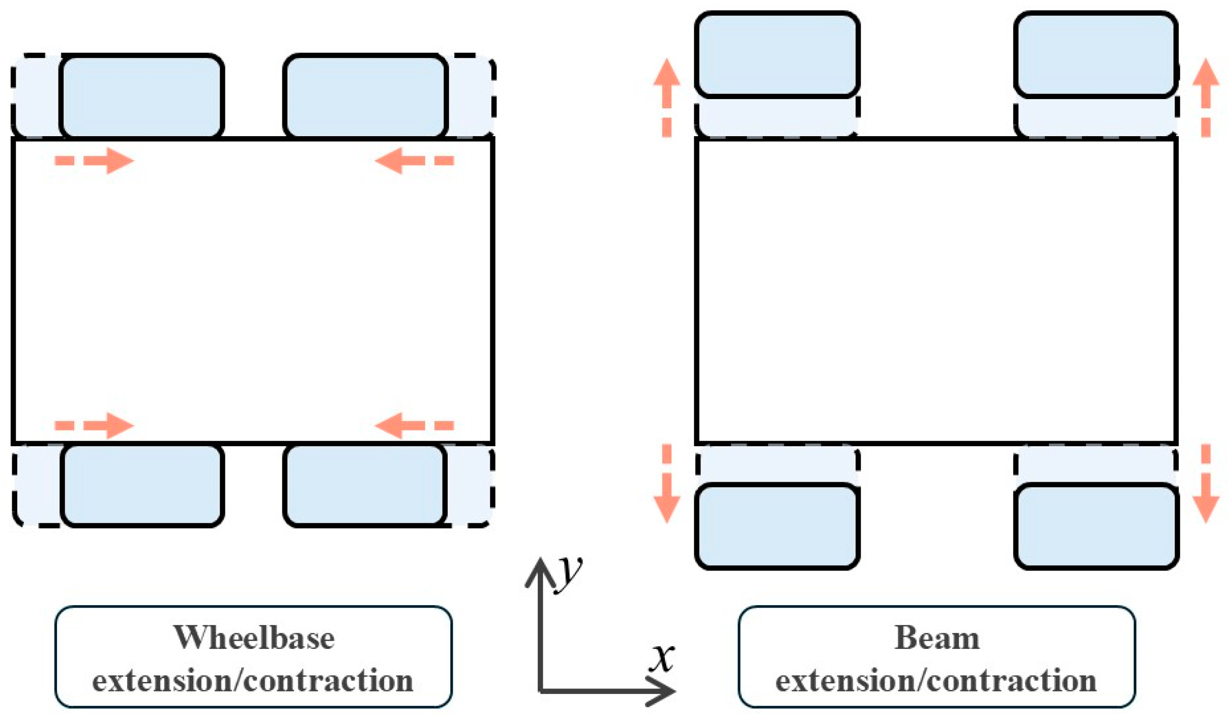
The typical method for recovering from sideslip is turning. This approach rotates the rover’s orientation from facing downhill to uphill by steering or by controlling the differential rotation of the left and right wheels. However, turning on the soft slope can easily lead to ground collapse and further sideslip. To address this issue, this study proposes a method that moves the rover directly toward the uphill side of the slope. The key features of this method are its high path-following performance and simplicity of control. By basing the recovery motion on direct movement toward the uphill side, this method does not require complex control algorithms or kinematic computations, enabling a simpler recovery process. Consequently, this approach is expected to recover without turning and reduce the risk of further deviation from the intended path. In this study, the term two-dimensional Push-pull Locomotion (2DPPL) refers to a locomotion method that enables the rover to move not only in the longitudinal (forward/backward) direction via wheelbase extension and contraction but also laterally (left/right) using beam extension and contraction mechanisms, as illustrated in Figure 5. The designation “two-dimensional” highlights that mobility is not confined to a single axis but instead encompasses two translational degrees of freedom on the slope surface. The objective of this research is to suppress sideslip and reduce attitude angle loss during slope traversal.

2. 2DPPL Mechanism and Theoretical Analysis

2.1. About Driving Wheel-Soil Interaction

The interaction forces generated during rover locomotion on soft terrain have been studied using terramechanics models [11,12,13,14]. To predict soil compaction and the resistance force, previous research has employed the Bekker presser-sinkage relationship, which describes the interaction between soil and a plate. The pressure exerted on the plate by the soil is given by Equation (1), involving b , h , k c , k ϕ , and n . Here, b is the width of the plate, h is the sinkage, and k c , k ϕ , and n are empirical constants that depend on soil properties.
σ h = k c b + k ϕ h n
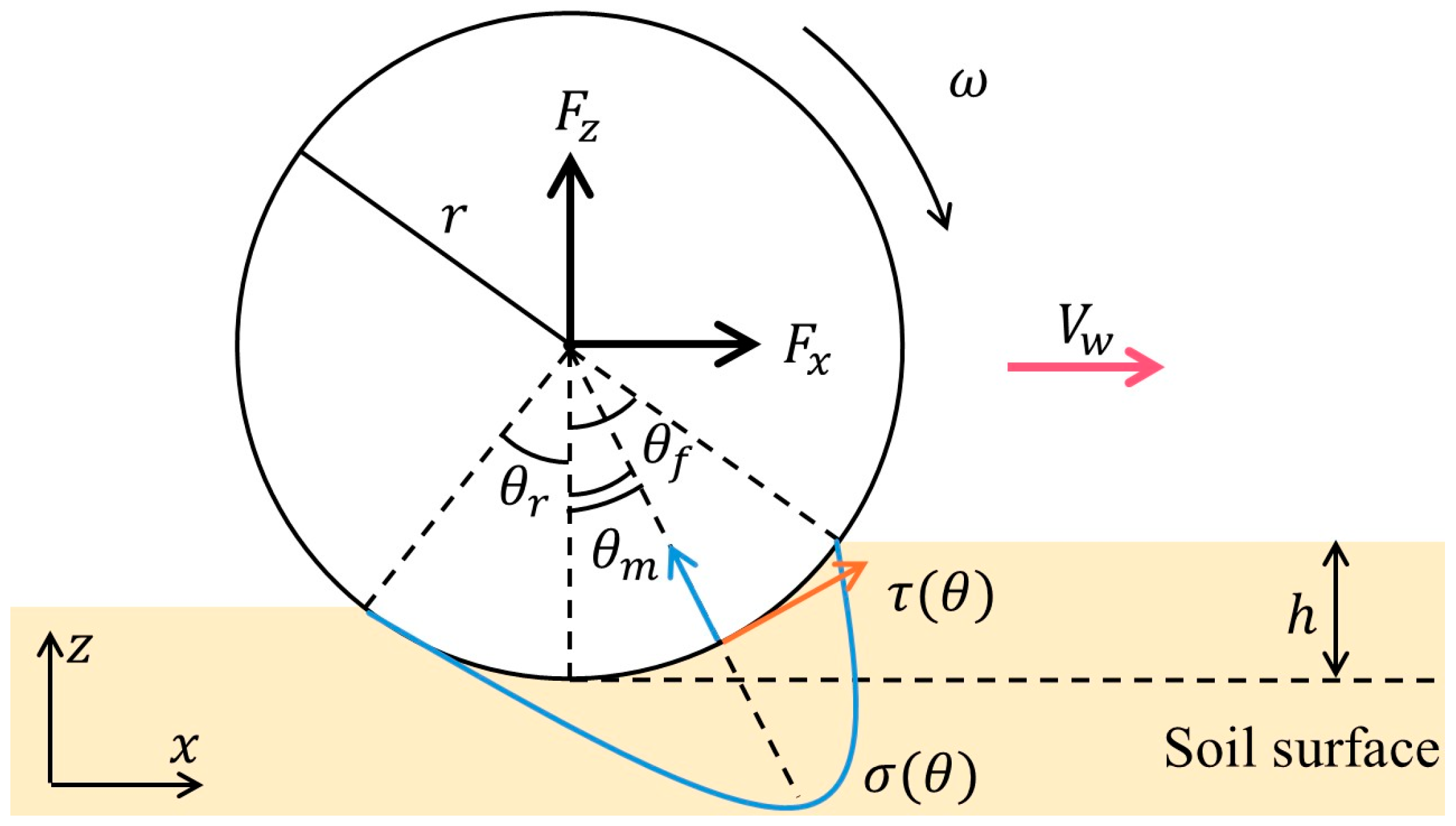
Next, the wheel-soil interaction model is illustrated in Figure 6. By applying Equation (1) to the wheel and substituting the wheel sinkage h θ at an arbitrary wheel angle θ , the normal pressure distribution along the wheel can be expressed as shown in Equation (2) [15]. In this equation, θ m represents the angle at which the normal pressure is maximized, as defined in Equation (3).
σ θ = r n k c b + k ϕ cos θ cos θ f n θ m θ < θ f r n k c b + k ϕ cos θ f θ θ r θ m θ r θ f θ m cos θ f n θ r < θ θ m
θ m = a 0 + a 1 s θ f
Here, a 0 and a 1 are parameters that depend on the wheel-soil interaction. In addition, s represents the slip ratio of the wheel. The shear stress acting along the wheel surface is the primary contributor to traction. The shear stress at an arbitrary wheel angle τ θ is expressed in Equation (4), using the parameters c , ϕ , k x , and σ θ , which represent the soil cohesion, internal friction angle, shear deformation modulus, and the normal stress along the wheel surface (as defined in Equation (2)), respectively [13]. The shear displacement of the soil j x is given in Equation (5) and is calculated using the entry and exit angles of the wheel-soil interaction, θ r and θ f [15].
τ θ = c + σ θ tan ϕ 1 e j x θ / k x
j x = r { θ f θ ( 1 s ) ( sin θ f sin θ ) }
Finally, using the normal stress σ θ , shear stress τ θ along the wheel surface, the wheel width b , and the wheel radius r , as illustrated in Figure 6, the driving force F x is expressed in Equation (6) [15].
F x = r b θ r θ f τ θ cos θ σ θ sin θ d θ
In addition, the wheel slip ratio s represents a parameter that depends on both τ θ and σ θ , and is also related to the parameters θ m and j x . The slip ratio s is expressed in Equation (7), using the wheel’s angular velocity ω [15]. The value of s ranges from −1 to 1. A value of s = 1 indicates that the wheel is operating under a high-slip condition.
s = r ω V w / r ω r ω > V w r ω V w / V w r ω < V w
Using the terramechanics equations introduced above, the driving force of the PPL wheels can be quantitatively estimated.

2.2. Resistance Force Between Wheel and Ground

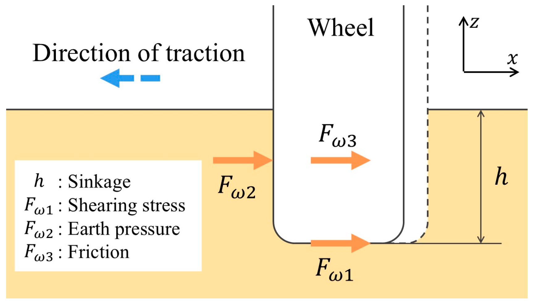
This section analyzes the resistance force acting on stationary wheels during locomotion based on wheelbase extension and contraction. The resistance force is defined as the maximum force that the ground can support before failure. When the rover moves using the wheelbase extension/contraction mechanism on soft terrain, as shown in Figure 7, the stationary wheels are subjected to three primary forces from the ground that oppose the force of the moving wheel. The first is the shear force F ω 1 acting on the underside of the wheel, caused by the shearing of the ground. The second is the resistive force F ω 2 from the ground wall, which arises when the wheel displaces soil by rotating or sinking. The third is the frictional force F ω 3 generated between the side of the wheel and the ground wall. The total resistance force F ω is defined as the sum of these three components, as given in Equation (8).
F ω = F ω 1 + F ω 2 + F ω 3
In addition, since the contribution of F ω 3 to the total resistance force F ω is relatively small, it is often neglected in previous studies [16]. Therefore, this paper considers the shear stress F ω 1 and the resistive force F ω 2 as the dominant components.

2.3. Effectiveness of Wheelbase Modulation in Slope Traversal

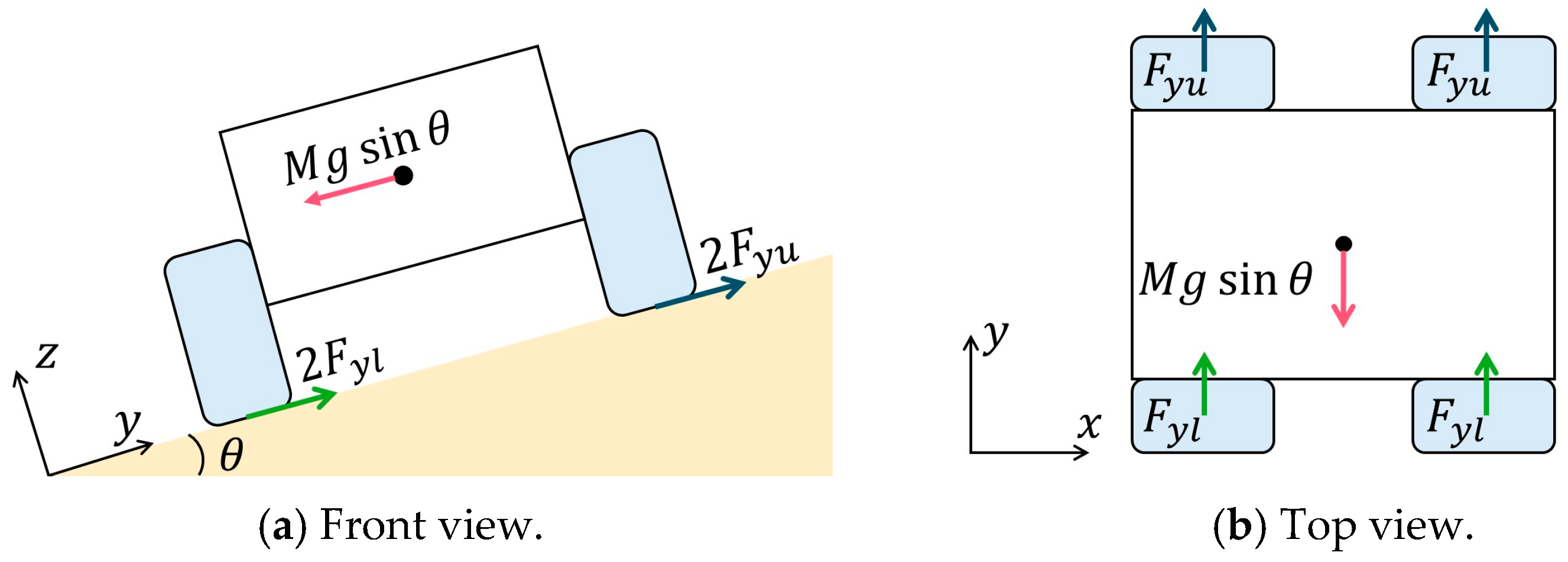
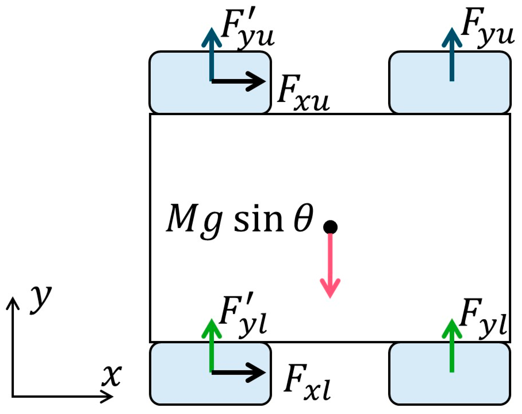
We analyze the forces generated during normal driving and APPL driving while traversing a slope. First, when the rover is stationary on the slope, the forces acting along each axis are balanced, as illustrated in Figure 8. Since the loads on the uphill and downhill sides of the slope differ, the ground reaction forces can be denoted as F y u and F y l , respectively. Their resultant force F y satisfies Equation (9). Furthermore, the component of gravitational force pulling the rover downhill in the horizontal direction is balanced by the uphill ground reaction force, as described by Equation (10).
F y = 2 F y u + 2 F y l
M g sin θ = F y
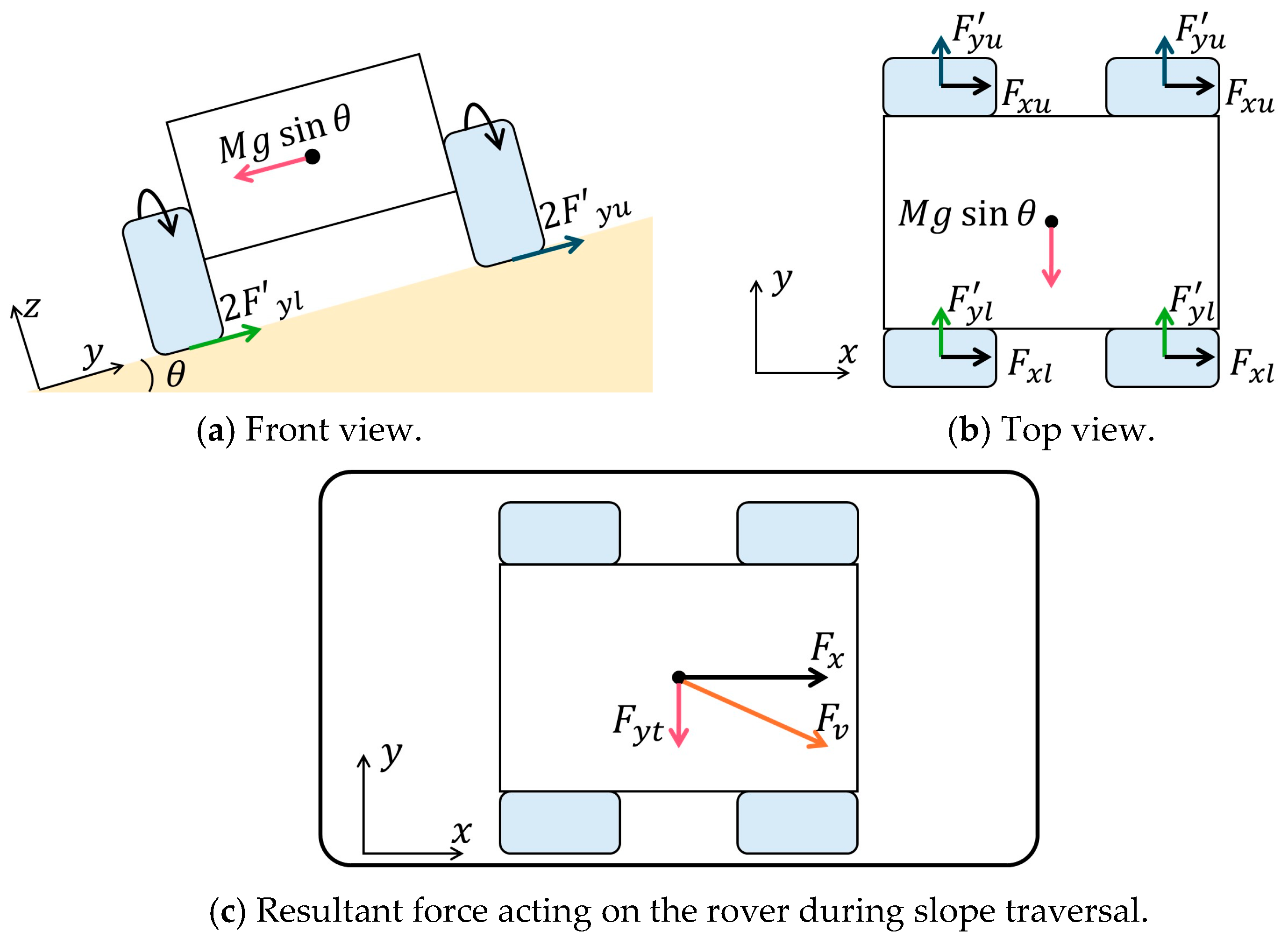
Next, Figure 9 presents a schematic diagram of the rover at the onset of normal driving. On soft terrain, the ground is more prone to collapse than on rigid terrain, leading to a reduction in the ground reaction forces F y u and F y l . These reduced forces are denoted as F y u and F y l , and their total reaction force F y is defined in Equation (11). The relationship between this total reaction force and the downslope component of gravity is described by Equation (12). The force acting parallel to the slope, F y t , is expressed by Equation (13) and represents the net downhill force resulting from the difference between the gravitational component along the slope and the vertical reaction forces. The driving force F x , which acts in the direction of travel as illustrated in Figure 9b, is given in Equation (14). The combination of F x and F y t results in a net force F v directed downhill as shown in Figure 9c. This downhill directed resultant force is considered a primary cause of sideslip.
F y = 2 F y u + 2 F y l
M g sin θ F y
F y t = M g sin θ F y
F x = 2 F x u + F x l
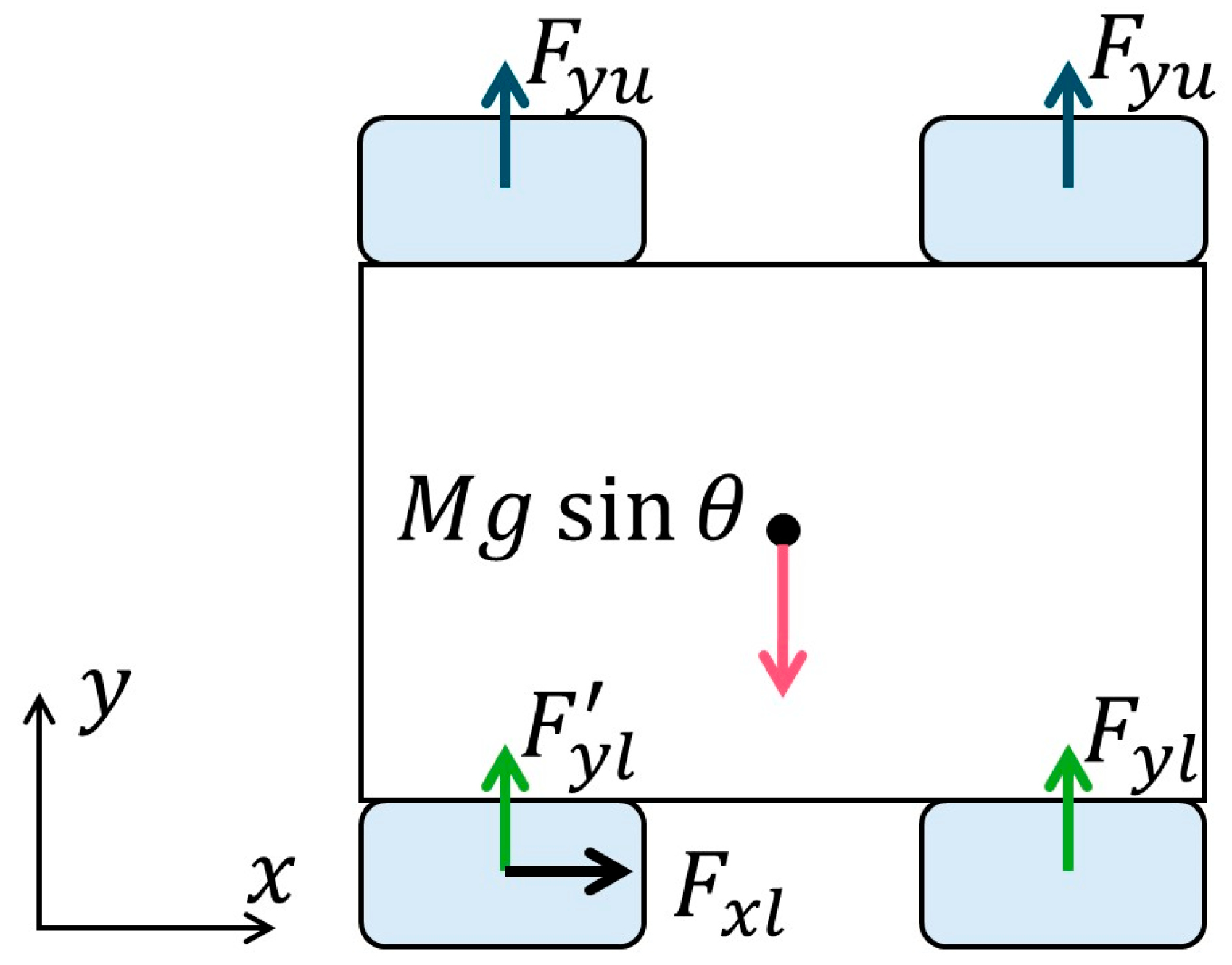
Next, the forces acting on the rover during slope traversal using the wheelbase extension and contraction method are analyzed. When the rover is stationary, the force balance is the same as shown in Figure 8. However, immediately after the rover begins to move, the situation differs from that of normal driving because only two wheels are actively driven. Figure 10 represents the case in which the rear wheels of the rover are driven. At this time, the reaction force from the ground, denoted as F y , can be expressed by Equation (15).
F y = F y u + F y l + F y u + F y l
Similarly, when using the four-wheel independent wheelbase extension and contraction method, the stationary force balance remains unchanged, but only one wheel is driven at a time once motion begins. This case is illustrated in Figure 11, and the corresponding ground reaction force F y is expressed in Equation (16).
F y = 2 F y u + F y l + F y l
Static wheels exhibit greater resistance force than dynamic wheels because sand fluidization is less likely to occur. In the wheelbase extension/contraction method, two rear wheels remain stationary while the front wheels are driven. Compared to normal driving, this configuration increases the total resistance force, and the relationship between the reaction forces can be represented by Equation (17). Furthermore, in the four- wheel independent wheelbase extension/contraction method, three wheels remain stationary while only one wheel moves. This further enhances the resistance force compared to the standard wheelbase extension/contraction method, as expressed by Equation (18).
F y > F y
F y > F y

2.4. Beam Extension and Contraction Method

Figure 12 illustrates the proposed beam extension and contraction method. In this method, the distance between the left and right wheels (beam) can be extended or contracted. Specifically, the rotational motion of the wheels is converted into linear motion along the axis by connecting the left and right wheels via a ball screw. Each wheel and body is controlled independently. When one wheel moves uphill, the remaining three wheels remain stationary, allowing effective use of shear force from the ground. As discussed in Section 2.3, increasing the number of stationary wheels enhances ground reaction forces and reduces the likelihood of skidding. Furthermore, since the rover can move laterally without changing its orientation, steering operations and yaw-axis rotations can be avoided. This ability to move directly uphill is particularly effective for correcting sideslip and maintaining a stable attitude angle.

2.5. Use of Screw Wheels

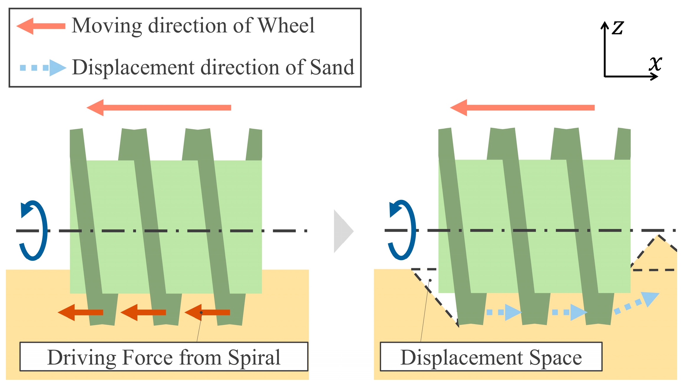
When a wheel moves laterally relative to the direction of the rover, a major issue arises due to significant earth pressure acting on the side surface of the wheel. This earth pressure is generated through interaction with the ground and acts as resistance when the side of the wheel pushes against the soil, making lateral movement extremely difficult. This problem is particularly prominent on soft ground, where the conventional wheel shape struggles to achieve effective lateral movement. To overcome this issue and enable lateral movement, the method proposed in this study adopts an Archimedean screw-shaped wheel. This design features a helical projection around the wheel, which allows for active interaction with the ground due to its unique geometry [17]. As shown in Figure 13, the helical projection pushes the ground backward as it rotates, creating space around the side surface of the wheel. This space reduces the earth pressure acting on the wheel’s side, thereby enabling more efficient lateral movement. In addition, the unique characteristics of the Archimedean screw shape contribute to the reduction of attitude angle loss during forward movement. As the screw wheel rotates, its helical projections excavate the ground and generate a continuous force toward the uphill side of the slope. This force directed toward the uphill side is expected to suppress lateral slippage on the slope. Furthermore, the discharged soil from the helical structure is expected to help prevent a drop in the rover’s attitude angle by accumulating on the downslope side of the wheel during lateral traversal, thereby supporting the wheel and reducing tilt. These characteristics of the screw wheel contribute to suppressing lateral slippage and minimizing attitude angle loss on soft or sloped terrain, where conventional circular wheels tend to lose traction.

3. Measurement of Sideslip During Slope Traversal Experiments

3.1. Testbed

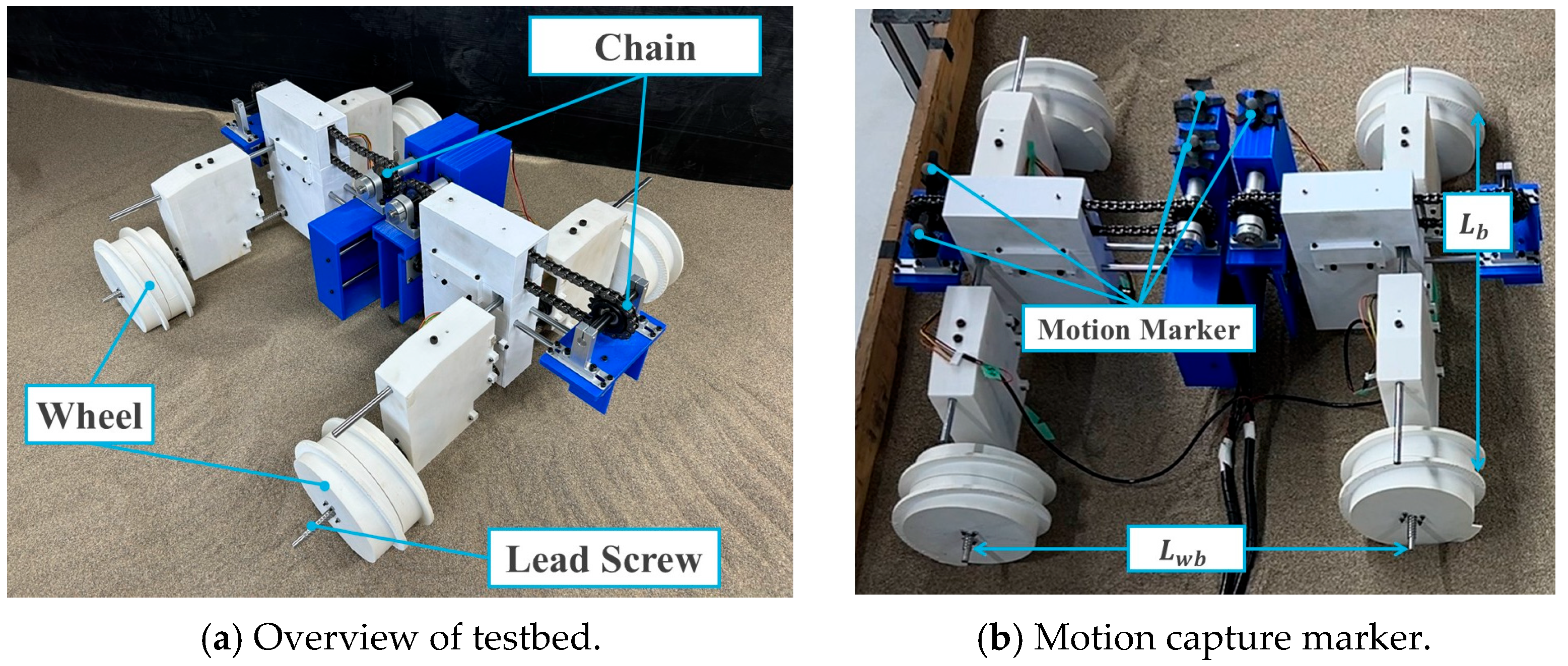
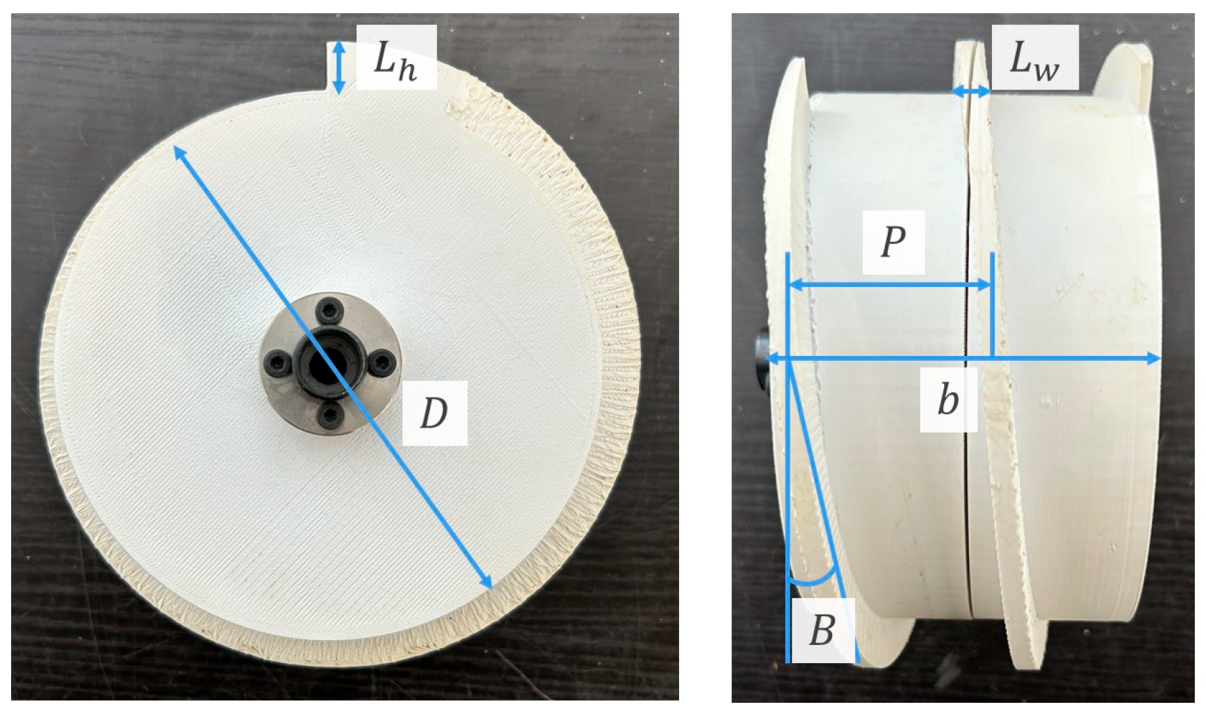
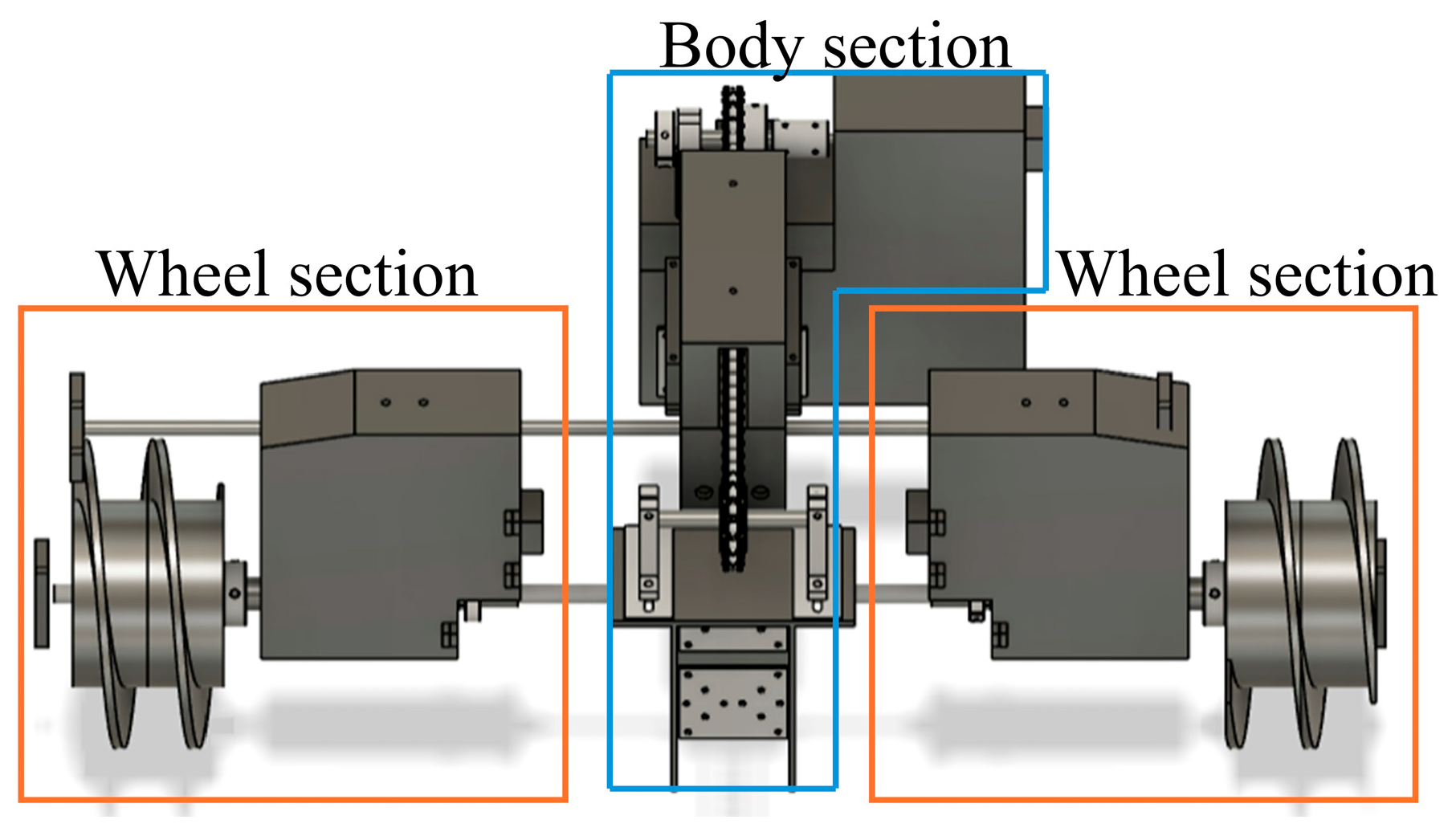
The test bed used in the experiment and its parameters are shown in Figure 14 and Table 1. The wheels used are shown in Figure 15, and their parameters are listed in Table 2. The test bed consists of four wheel sections and two body sections located at the front and rear. The left and right wheels are connected via a ball screw along the axle, allowing beam expansion and contraction through the parallel movement of the wheels along the screw. The overview of the proposed mechanism is shown in Figure 16. This mechanism is largely divided into two parts: the wheel section and the body section.
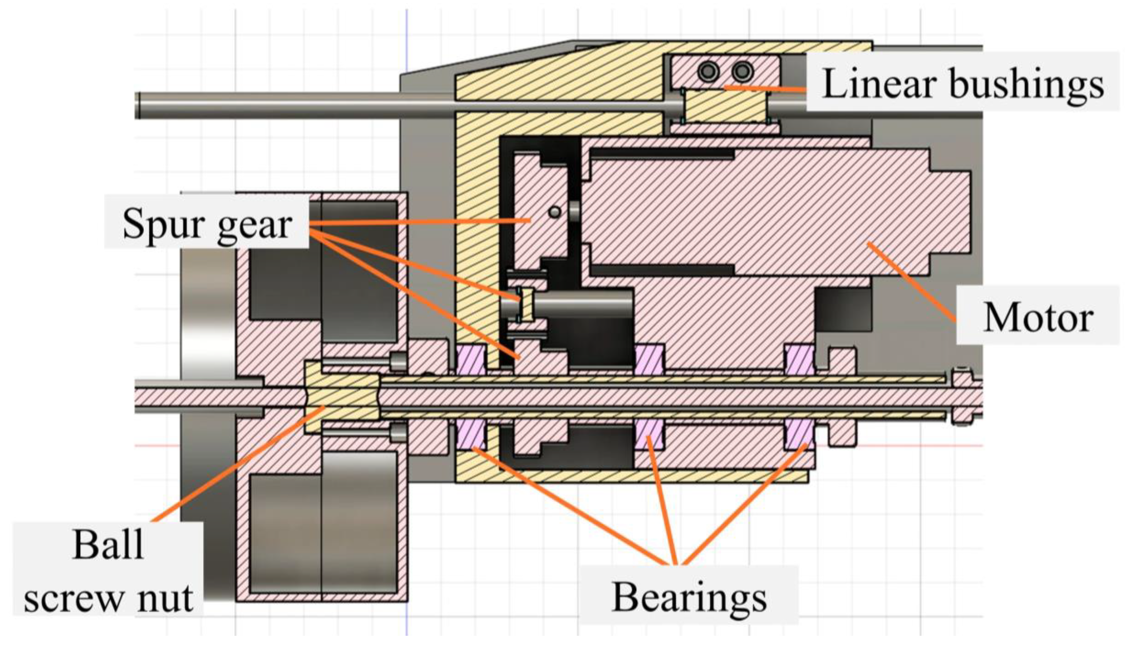
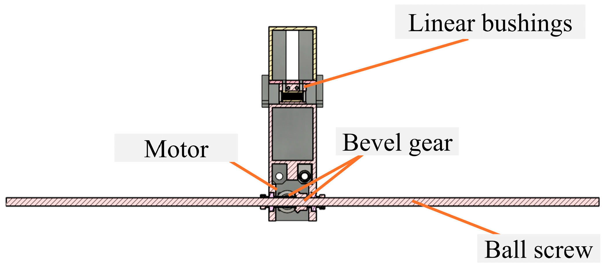
A cross-sectional view of the wheel section from the rear of the rover is shown in Figure 17. The motor mounted to the wheel section rotates the spur gear and transfers power to the wheel. The motor attached to the wheel section rotates a spur gear to transmit power to the wheel. Since a ball screw nut is embedded inside the wheel, the wheel can move linearly along the screw as it rotates. In addition, a cross-sectional view of the body section as seen from the rear of the rover is shown in Figure 18. A bevel gear attached to the motor in the body section is connected to the ball screw. Since this setup allows the ball screw itself to rotate, it is possible to stop the wheels and move only the body section in the lateral direction. To achieve idle rotation without causing translational motion due to the screw mechanism, the wheel and the shaft (ball screw) are rotated simultaneously at the same RPM. This setup ensures that the system behaves as intended, allowing rotation without lateral displacement. This synchronization prevents unintended lateral movement during forward motion. Next, the actuator drives the chain to perform the wheelbase expansion and contraction. When the body section and the left and right wheels, which are attached to the chain, move in the longitudinal direction, the wheelbase expands or contracts accordingly. Sprockets are mounted at the frontmost and rearmost ends, and a centrally placed motor rotates the chain. Linear bushings assist the linear motion.

3.2. Experimental Environment and Condition

An overview of the experimental apparatus is provided in Table 3, and the experimental set is illustrated in Figure 19. The testbed consists of a sandbox filled with silica sand No. 5 (see Table 4), measuring 1500 mm in width, 2000 mm in length, and 150 mm in depth. The slope of the sandbox can be adjusted. For measurements, a motion capture system consisting of optical cameras and reflective markers is used to track the position and movement of objects. A total of nine motion markers are placed, with four on the corners of the sandbox and five on the testbed, as shown in Figure 14b. Table 5 summarizes the experimental conditions.
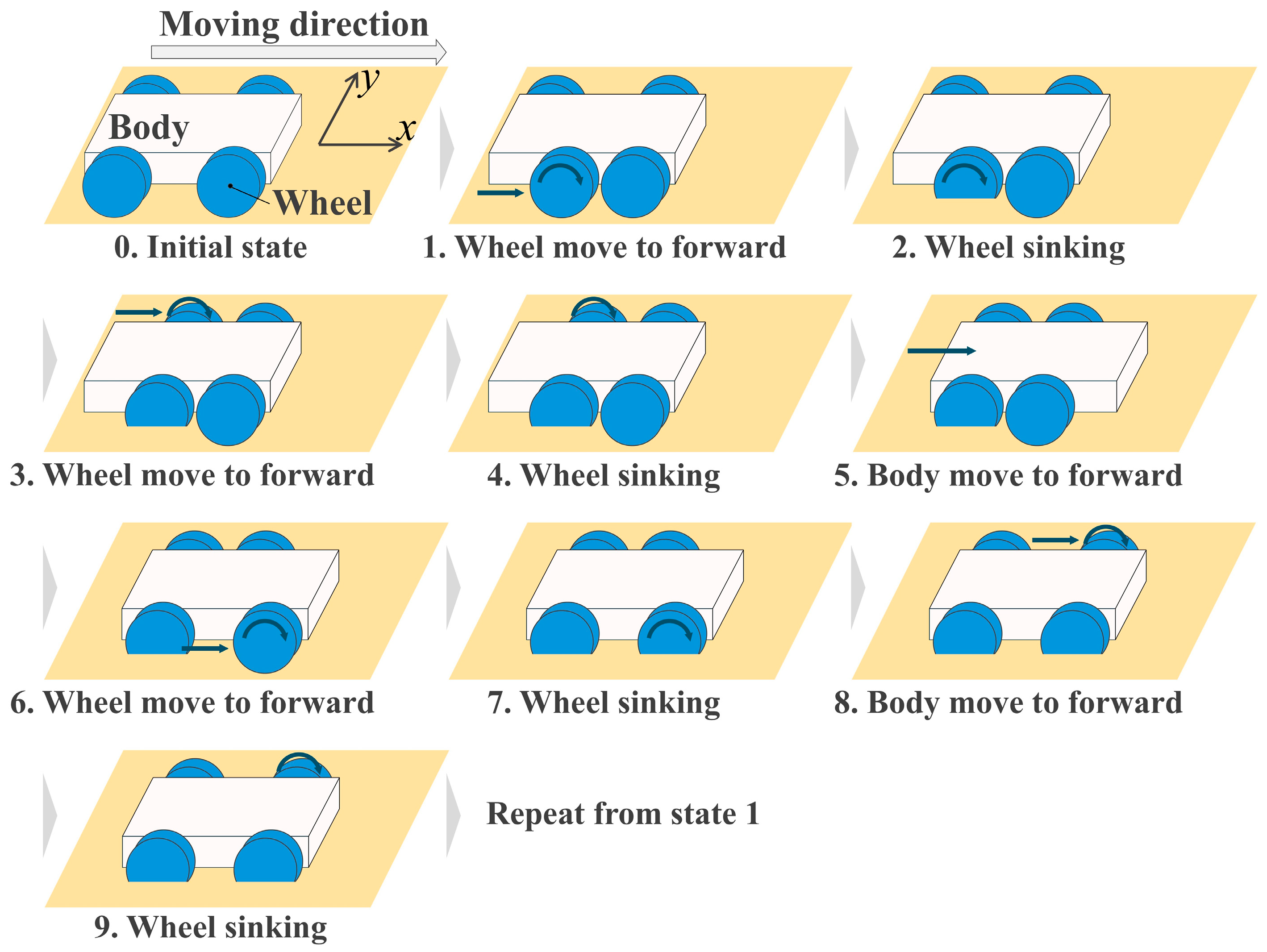
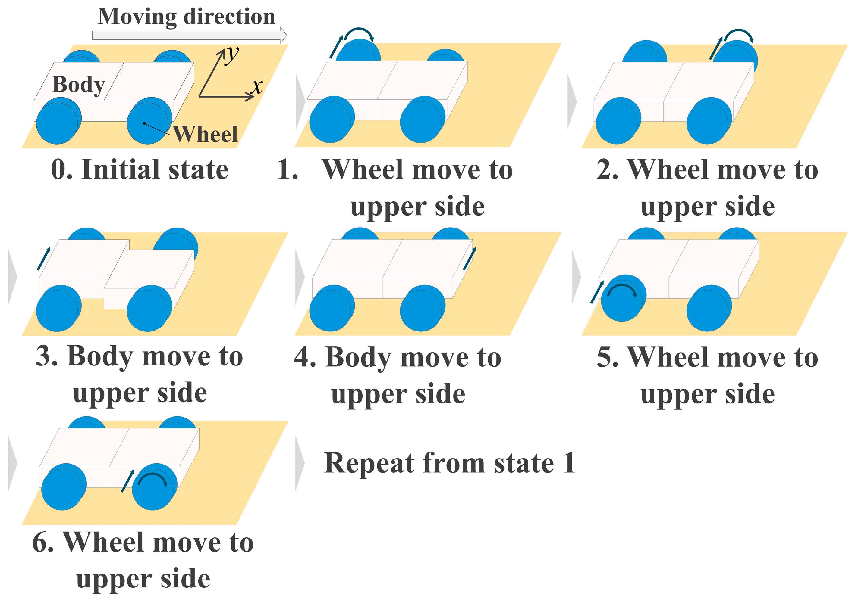
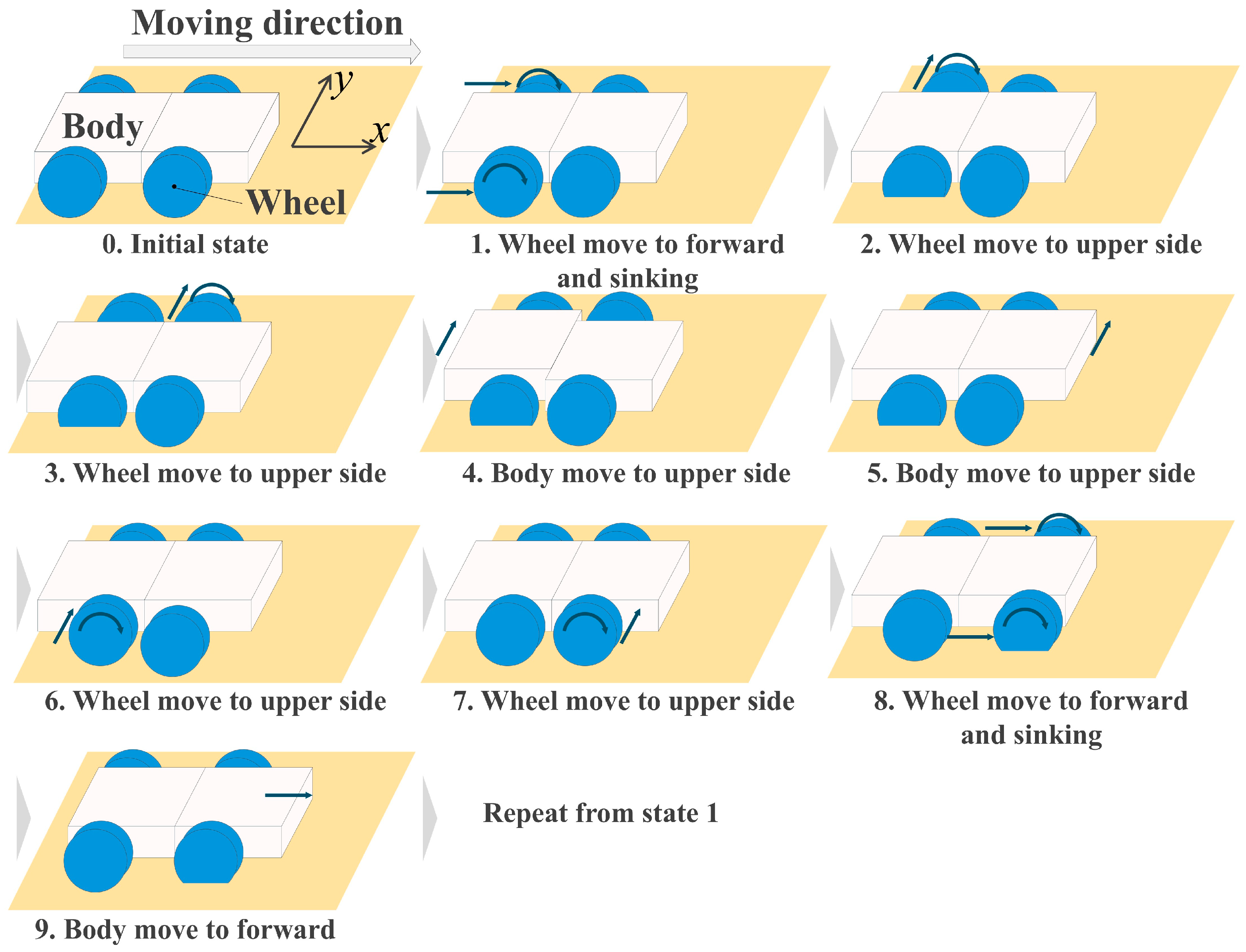
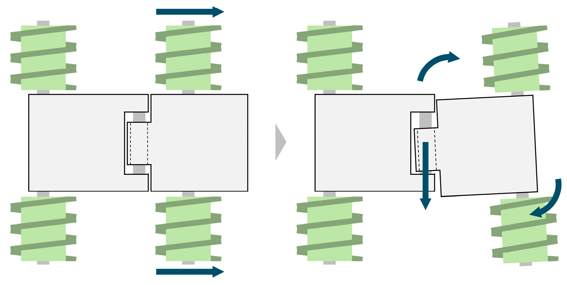
Three driving methods are tested: normal driving, APPL driving, and 2DPPL driving. The amount of sideslip and the change in attitude angle are measured using a motion capture system after the rover travels 500 mm along the x-axis. Normal driving refers to the conventional method in which all four wheels rotate simultaneously. APPL driving involves performing wheelbase extension and contraction to move. 2DPPL driving alternates between wheelbase extension/contraction movements and beam extension/contraction, as illustrated in Figure 20. During this process, the rover shifts laterally by 10 mm toward the uphill side of the slope.

4. Results

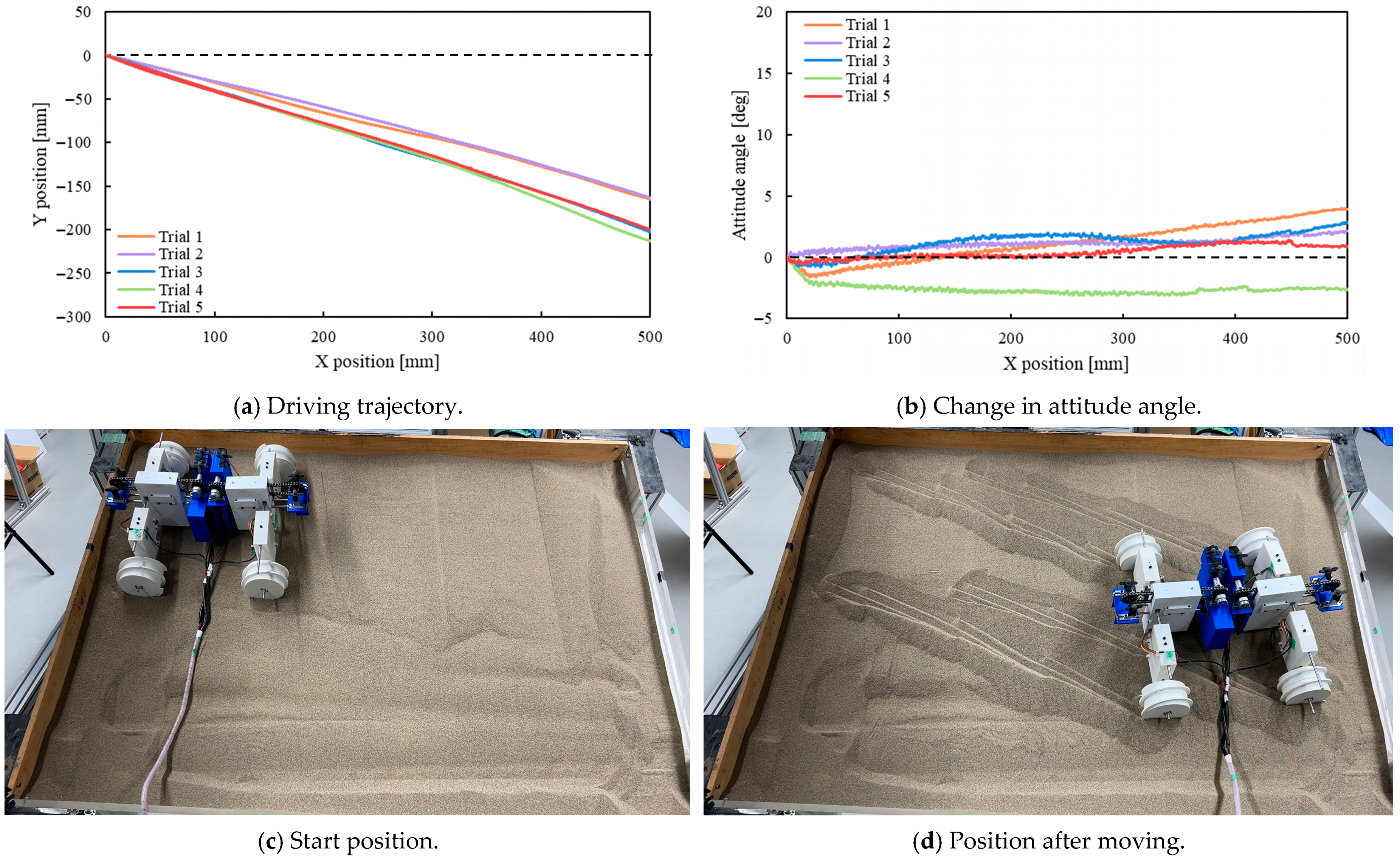
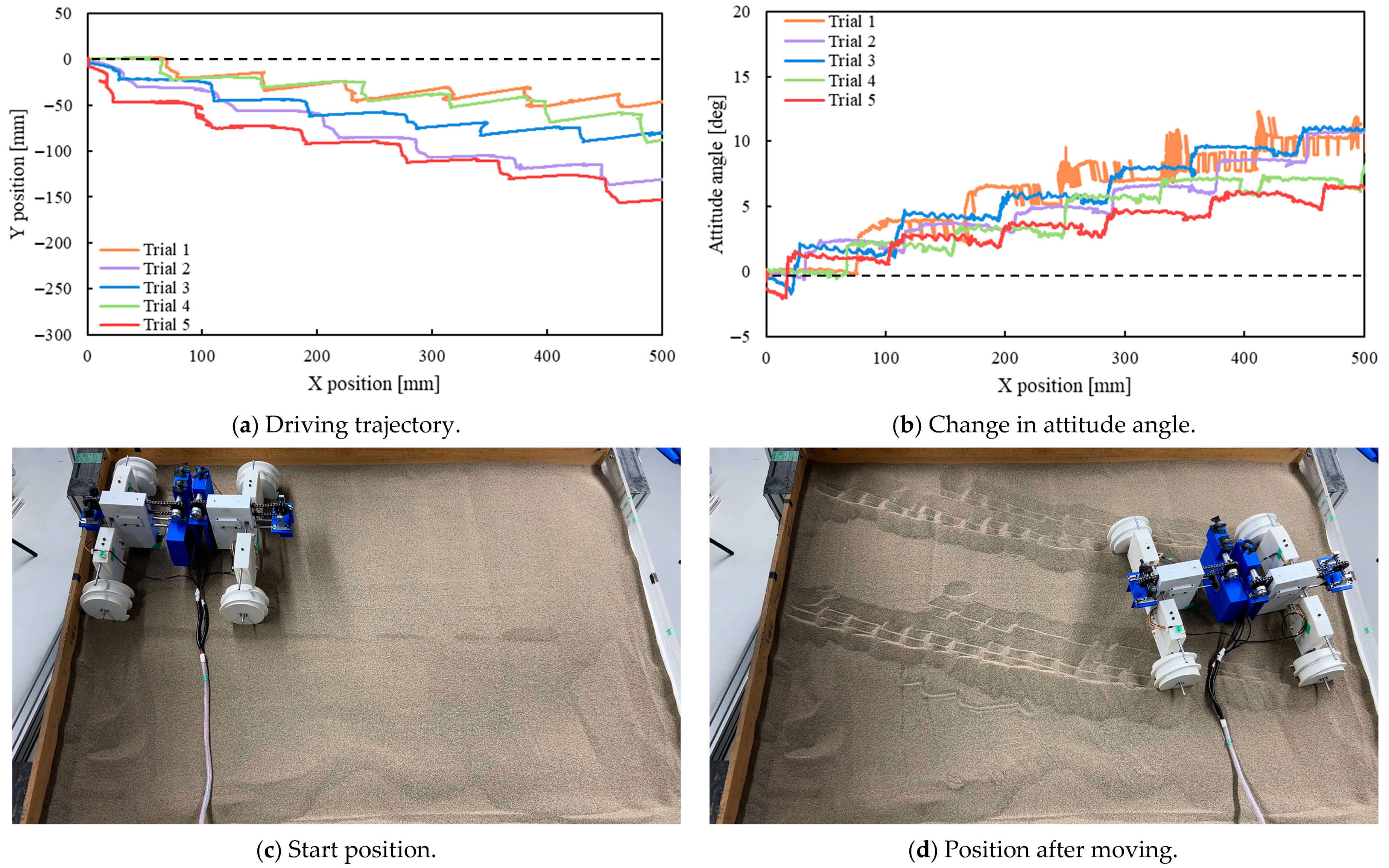
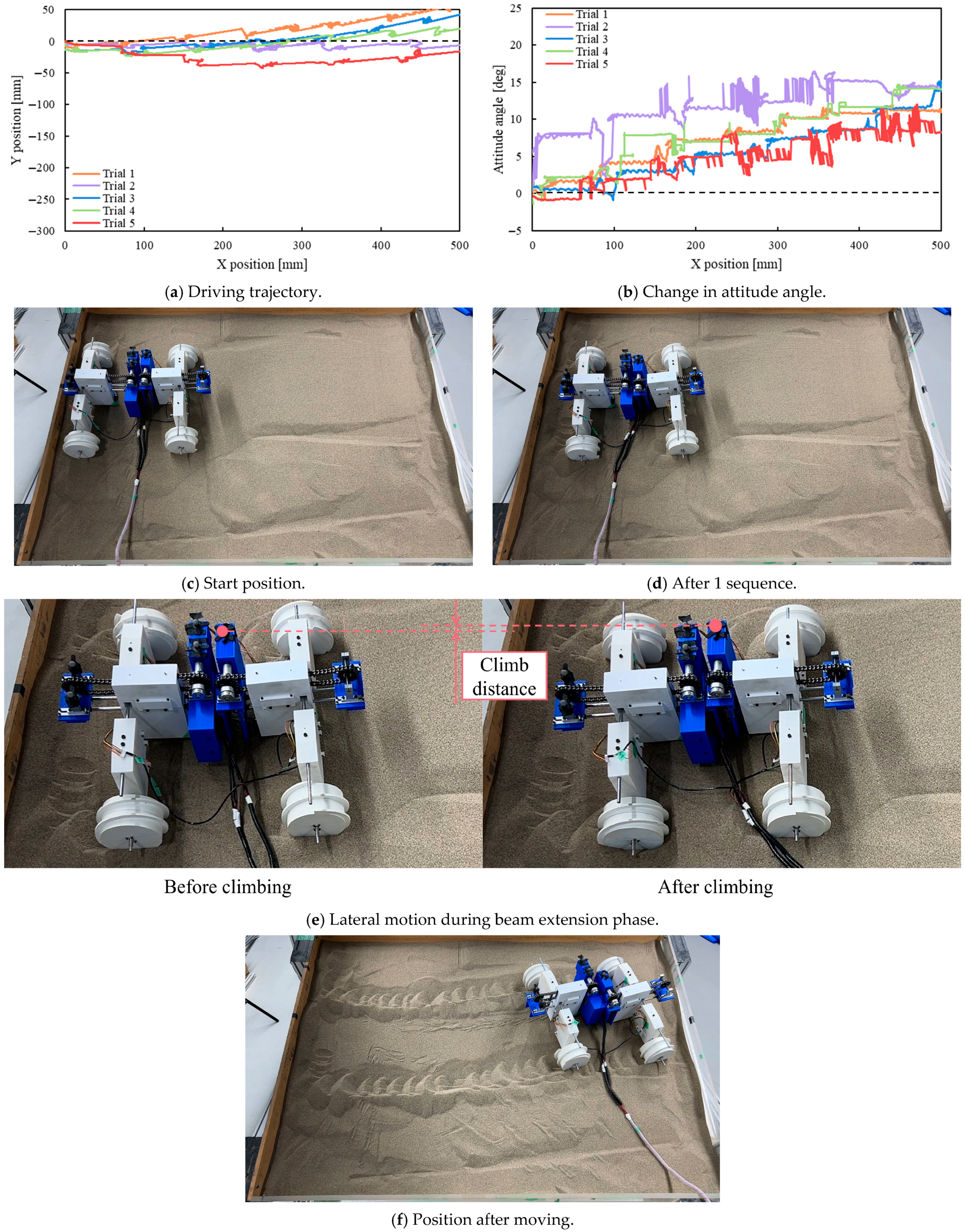
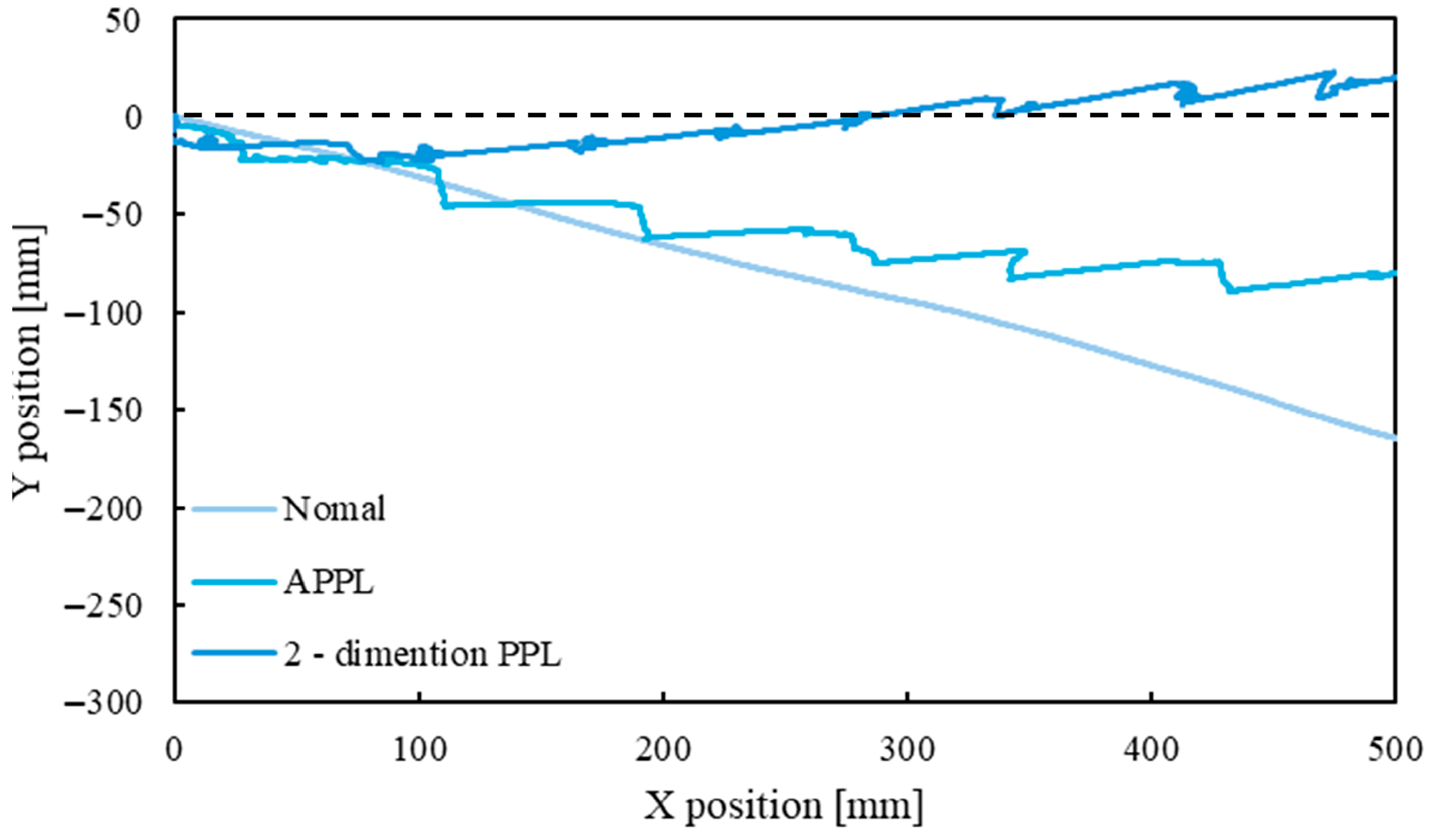
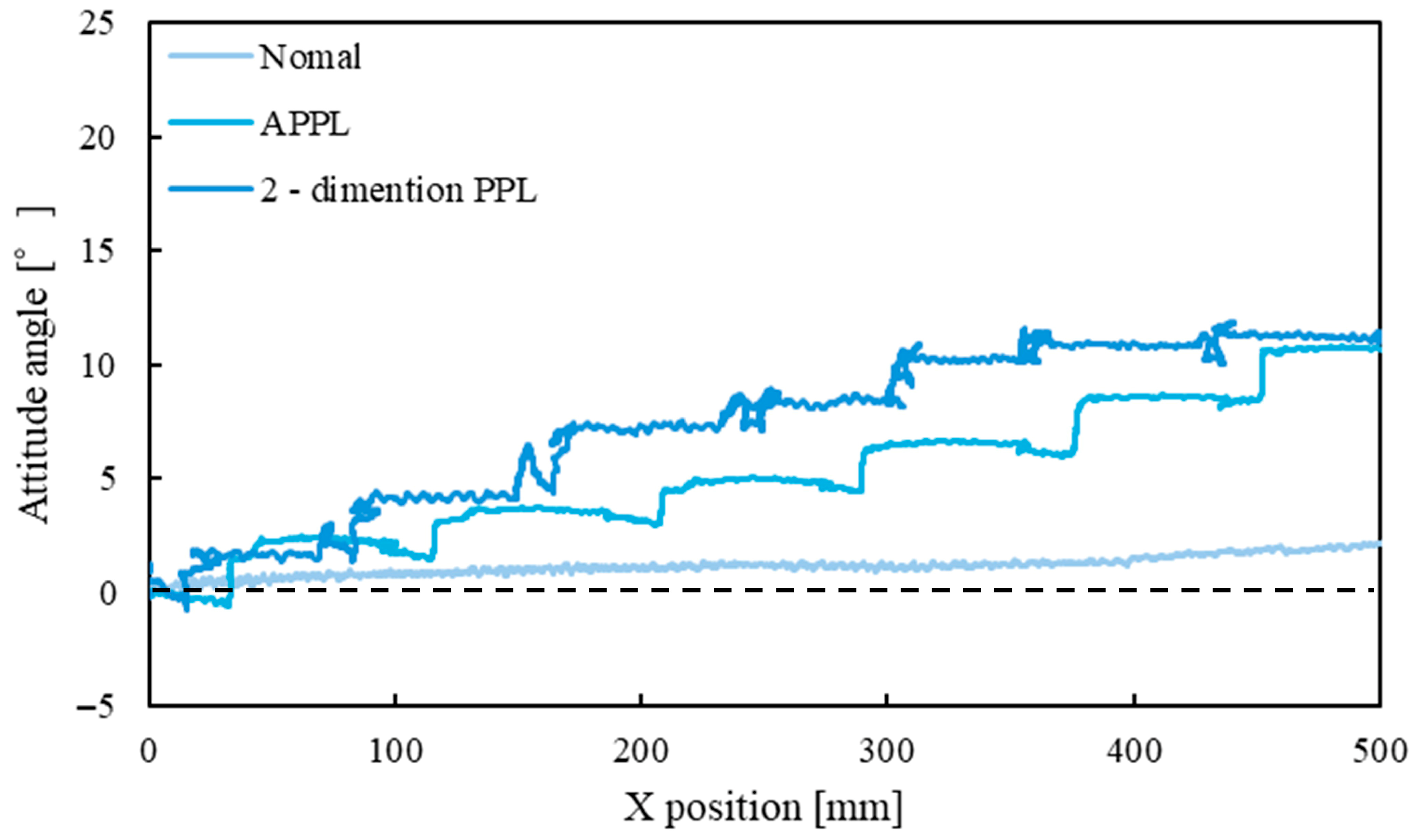
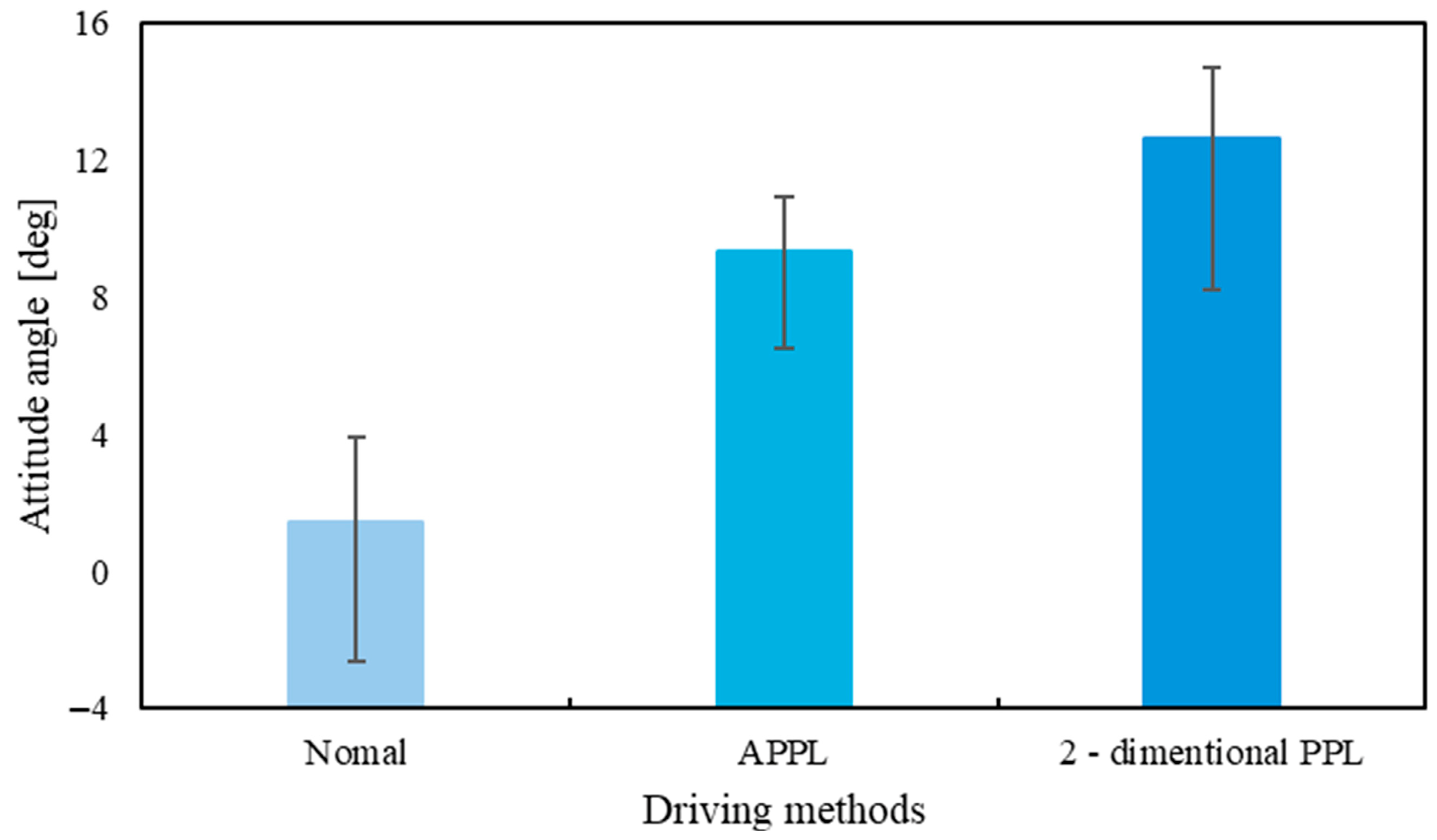
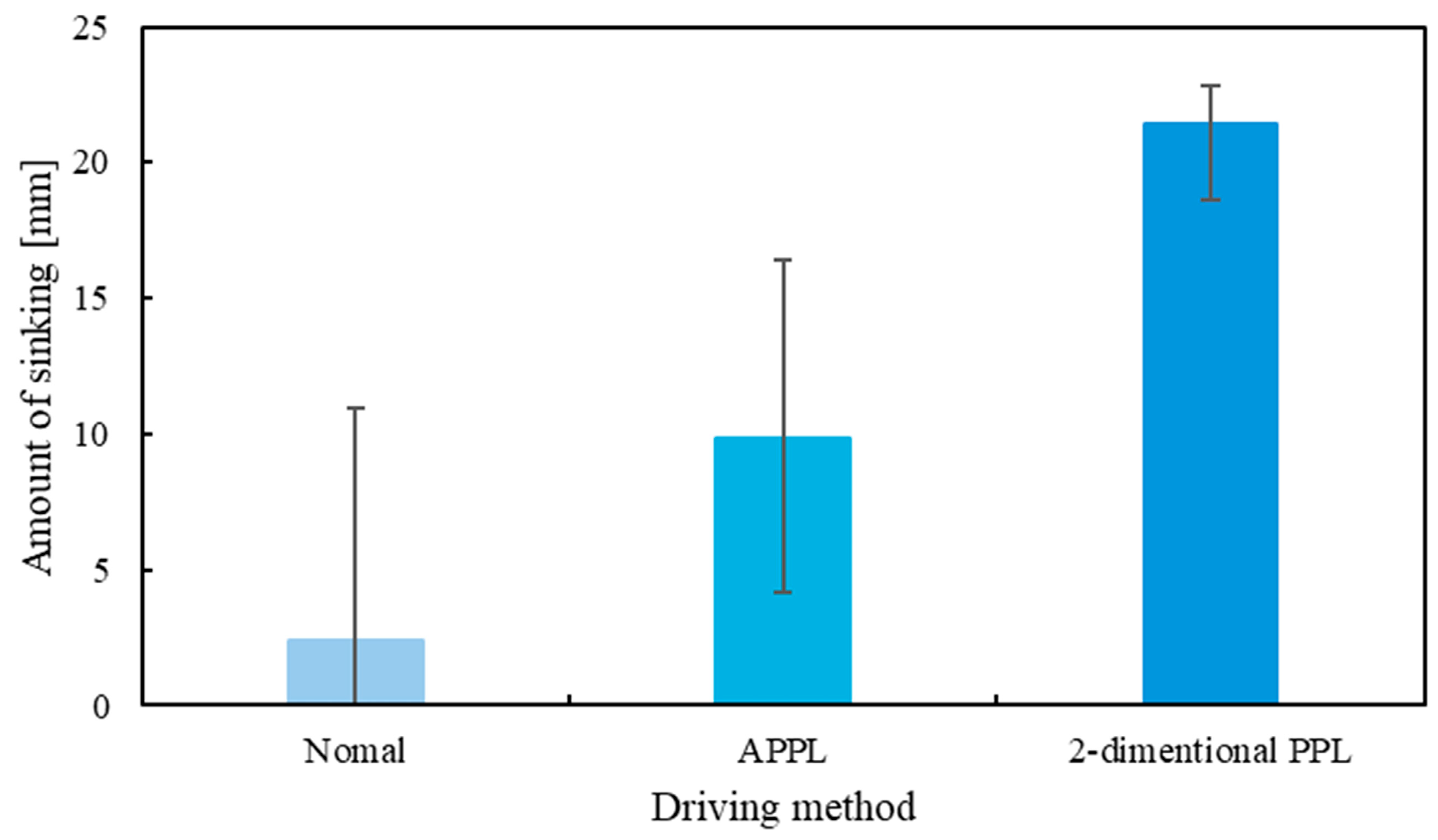
Figure 21, Figure 22 and Figure 23 show the driving trajectories, the changes in attitude angle, the start of driving, and the end of driving for each trial of the three driving methods. Especially, Figure 23c–f presents the sequence of driving from the start of traveling to the end of traveling by wheelbase extension/contraction and beam extension/contraction movement. Figure 23e shows a comparison of the rover’s position before and after beam extension/contraction. A clear lateral movement toward the uphill side of the slope can be observed. While the beam mechanism was designed to achieve a 10 mm lateral shift, the actual displacement measured during 2DPPL driving was approximately 6 mm. Figure 24 and Figure 25 show a comparison of the driving trajectories and changes in attitude angle during slope traversal for the three driving methods. The result that showed the median values of both the amount of lateral slip and the change in heading angle among the five trials was used as the representative result. Figure 26 presents the average change in attitude angle after the rover traveled 500 mm. The error bars indicate the maximum and minimum values. Figure 27 displays the maximum dynamic settlement observed during each trial, with the error bars defined in the same manner as in the previous figure. Among the three methods, normal driving exhibited the greatest amount of sideslip, whereas 2DPPL driving suppressed sideslip most effectively. Compared to normal driving, APPL driving reduced sideslip by approximately 50%. In addition, 2DPPL driving showed the largest dynamic settlement during travel.

5. Discussion

5.1. Discussion of Slope Traversal Experiment

The experimental results indicate that the normal driving method exhibited the greatest amount of sideslip, whereas the 2DPPL driving method was most effective in suppressing it. The APPL method reduced sideslip by approximately half compared to normal driving. This reduction is attributed to recovery movements, increased attitude angle, and enhanced sinkage, which collectively improved the rover’s traction and stability.
In the 2DPPL method, the rover demonstrated a lateral shift toward the uphill side following beam extension and contraction. Although the testbed was designed to enable 10 mm of lateral movement, the observed displacement was approximately 6 mm. This discrepancy suggests that sideslip occurred during beam movement, leading to a deviation from the intended trajectory.
Changes in attitude angle were also identified as a key factor in suppressing sideslip. In all driving methods, the rover maintained its attitude without tilting toward the downhill side. However, during APPL and 2DPPL driving, a noticeable tilt toward the uphill side was observed. This may be due to the screw-shaped wheels and the lateral soil displacement caused by wheelbase and beam extension/contraction. Specifically, since the wheels are designed as right-handed screws, soil tends to accumulate on the downhill side during rotation, resulting in an uphill moment that tilts the rover.
The most significant changes in attitude occurred during wheelbase operations. For example, when the front wheelbase extended, the front section of the rover slightly dropped, producing an uphill moment (see Figure 28). In the 2DPPL method, lateral movement combined with wheel rotation further contributed to this uphill tilt and may have caused slippage in the driving wheels.
The differences in sideslip between APPL and 2DPPL methods are also considered to result from variations in dynamic sinkage. Among the three methods, 2DPPL exhibited the greatest settlement. This deeper sinkage likely enhanced the wheel’s supporting force, thereby reducing sideslip. During beam movement, the wheels rotated laterally and sank further into the soft terrain, increasing traction and stabilizing motion.
Some variability was observed in the experimental results, particularly in measurements of sideslip and sinkage. This may be attributed to minor inconsistencies in the initial rover positioning and slight variations in ground compaction, despite efforts to level the testbed and confirm soil strength through vane shear testing. These factors may have influenced wheel–soil interaction and led to deviations from the ideal path. Nevertheless, overall trends and differences between the driving methods remained consistent across trials.

5.2. Implications for Planetary Exploration

While this study successfully demonstrated the effectiveness of the proposed mechanism under Earth gravity, several challenges must be addressed before applying it to actual planetary exploration missions. These challenges include adaptation to reduced gravity, compatibility with planetary regolith characteristics, mechanical durability, and energy efficiency evaluation.
On celestial bodies such as the Moon or Mars, lower gravitational acceleration reduces normal force on the wheels, leading to diminished traction. Additionally, planetary regolith often exhibits high particle angularity, low cohesion, and reduced friction compared to Silica Sand No. 5. These characteristics could increase the risk of terrain collapse during maneuvers requiring strong traction. However, the 2DPPL method—allowing lateral recovery without sharp turns—could reduce shear stress on the surface and mitigate these effects.
The current prototype lacks a suspension system and connects the left and right wheels rigidly, limiting its adaptability to rough or rocky terrain. This restricts terrain conformity on planetary surfaces. Moreover, the beam and wheelbase mechanisms require multiple actuators, presenting a significant challenge in energy-limited environments.
Future work should aim to simplify the mechanical structure, reduce the number of actuators, and improve adaptability to uneven terrain and extraterrestrial soil. Evaluating the system under simulated low-gravity conditions and with regolith analogs will also be critical in assessing its viability for real space missions.

6. Conclusions and Future Work

This study proposed a sideslip recovery method that moves the rover directly toward the uphill of the slope by integrating beam extension/contraction and Archimedean screw wheels. The effectiveness of the proposed method was validated through slope traversal experiments.
The main contributions of this study are as follows:
A two-dimensional Push-Pull Locomotion (2DPPL) method, which combines beam extension/contraction and Archimedean screw wheels with wheelbase extension/contraction, was proposed and experimentally shown to significantly suppress sideslip during slope traversal compared to both normal (wheel-only) and APPL driving.
The experiments also showed that the 2DPPL method effectively prevented a decrease in attitude angle. However, both the APPL and 2DPPL method resulted in unintended increases in the attitude angle.
It was confirmed that beam extension/contraction induced wheel sinkage during the recovery motion, which contributed to increased ground support.
From these findings, it was concluded that the proposed 2DPPL method using beam extension/contraction is effective in suppressing both sideslip and attitude angle drop during slope traversal.
The following issues remain as future work:
Optimization of recovery displacement and operation sequence.
Redesign of the beam extension and contraction mechanism.
Investigation of alternative screw wheel geometries.
Evaluation under reduced gravity conditions and with extraterrestrial regolith simulants.
First, it is expected that modifying the recovery displacement and operation sequence during beam extension and contraction will allow the rover to return to its pre-sideslip attitude. Additionally, a redesign of the beam mechanism is needed. One identified cause of unintended increases in attitude angle is the sliding section at the center of the chassis. In future designs, mechanically linking the split center section of the rover could simplify the lateral motion by allowing simultaneous lifting of the front and rear axles. This may eliminate the need for sequential lifting steps, thereby reducing the time and complexity of the recovery motion. This redesign would also reduce that number of motion phases, thereby shortening the overall operation time. Next, experimental results showed that the amount of sinkage during lateral movement was greater than the actual lateral displacement. In other words, beam extension and contraction caused the wheels to sink in place. It is considered that improving the lateral movement efficiency—by modifying the wheel geometry or adjusting the pitch of the ball screw—will lead to more effective traversal performance. Finally, evaluation under reduced gravity conditions and extraterrestrial regolith simulants is essential to assess the feasibility of the proposed method in realistic planetary environments. These efforts will contribute to the development of more robust and adaptive locomotion systems for future planetary exploration missions.

Author Contributions

Conceptualization, K.S.; methodology, D.F. and K.I.; formal analysis, K.S.; resources, K.S.; data curation, K.S.; writing—original draft preparation, K.S.; writing—review and editing, D.F. and K.I.; visualization, K.S.; funding acquisition, K.I. All authors have read and agreed to the published version of the manuscript.

Funding

This research was funded by JSPS KAKENHI grant number JP24K07409.

Data Availability Statement

The raw data supporting the conclusions of this article will be made available by the authors on request.

Conflicts of Interest

The authors declare no conflicts of interest.

Nomenclature

ModulusUnitName of parameters
a 0 , a 1 -Bottom area of soil wedge A
b mmWidth of wheel
B ° Lead angle
c kN/m2Soil cohesion
D mmDiameter of wheel
F v NNet driving force
F x NDriving force
F x u NDriving force of upper wheel
F x l NDriving force of 
F y NTotal ground reaction force
F y NTotal ground reaction force (normal driving)
F y NTotal ground reaction force (APPL)
F y NTotal ground reaction force (4WAPPL)
F y l NGround reaction force (uphill)
F y l NGround reaction force (uphill, dynamic)
F y t NForce acting parallel to slope
F y u NGround reaction force (downhill)
F y u NGround reaction force (downhill, dynamic)
F ω NTotal resistance force
F ω 1 NShear force acting on the underside of the wheel
F ω 2 NResistive force from soil deformation by the wheel
F ω 3 NLateral friction between wheel sidewall and soil
h mmSinkage
j x mShear displacement
k c N/mn+1Pressure-sinkage modulus
k x mShear deformation modulus
k ϕ N/mn+2Pressure-sinkage modulus
L b mmBeam length
L h mmHeight of lug
L w mmWidth of lug
L w b mmWheelbase length
M NWeight
n -Slip ratio
P mmPitch
r mmWheel radius
s -Slip ratio
V w mm/sWheel driving velocity
θ ° Wheel angle
θ f ° Wheel contact angle
θ m ° Angle of the maximum normal stress
θ r ° Wheel exit angle
σ θ N/m2Normal stress
τ θ N/m2Shear stress
ω rad/sAngular velocity

References

  1. Marshall, S.; Douglas, C.; Nicole, H.; Erin, M.; Jonathan, K.; Nate, M.; Kandyce, G. The Artemis Program: An Overview of NASA’s Activities to Return Humans to the Moon. In Proceedings of the 2020 IEEE Aerospace Conference, Big Sky, MT, USA, 7–14 March 2020; pp. 1–7. [Google Scholar] [CrossRef]
  2. Takayuki, I.; Seisuke, F.; Kazuki, K.; Hiroyuki, K.; Keiki, T.; Hirohisa, K.; Shujiro, S.; Shinichiro, S. Vision-based navigation and obstacle detection flight results in SLIM lunar landing. Acta Astronaut. 2025, 226, 772–781. [Google Scholar] [CrossRef]
  3. Stefano, C.; Chit, H.Y.; Yuichi, T.; Naoko, O.; Yasuhiro, K. Mission analysis for the Martian Moons Explorer (MMX) mission. Acta Astronaut. 2018, 146, 409–417. [Google Scholar] [CrossRef]
  4. Christopher, D.K.H.; Tanja, B.; Elisabeth, M.H.; Keyron, H.L.; Lisa, E.M.; Dabid, L.S.; Sandra, S.; Justin, I.S.; Benjamin, P.W.; Meenakshi, W.; et al. Sampling Mars: Geologic context and preliminary characterization of samples collected by the NASA Mars 2020 Perseverance Rover Mission. PNAS 2025, 122, e2404255121. [Google Scholar] [CrossRef]
  5. Arvidson, R.E.; Ashley, J.W.; Bell, J.F., III; Chojnacki, M.; Cohen, J.; Economou, T.E.; Farrand, W.H.; Fergason, R.; Fleischer, I.; Geissler, P.; et al. Wolff. Opportunity Mars Rover mission: Overview and selected results from Purgatory ripple to traverses to Endeavour crater. J. Geophys. Res. Planets 2011, 116, E00F15. [Google Scholar] [CrossRef]
  6. David, W.; Scott, M.; Krzysztof, S.; Dominic, J.; David, K.; James, T. Design and field experimentation of a prototype Lunar prospector. Int. J. Robot. Res. 2010, 29, 1550–1564. [Google Scholar] [CrossRef]
  7. Wiebke, B.; Leon, D.; Amrita, S.; Mehmed, Y.; Manuel, M.; Frank, K. Development strategies for multi-robot teams in context of planetary exploration. In Proceedings of the 2024 International Conference on Space Robotics (iSpaRo), Luxembourg, 24–27 June 2024; pp. 64–69. [Google Scholar] [CrossRef]
  8. Daisuke, F.; Naoki, T.; Tetsuya, O.; Kojiro, I. Analysis of a resistance force for the locked-wheel of push-pull locomotion rovers using large subsidence. J. TerraMech. 2021, 94, 1–12. [Google Scholar] [CrossRef]
  9. Kohei, I.; Kojiro, I. Proposal of a Planetary Exploration Rover with a Wheel using Sinking Performance for Crossing Slope. J. Robot. Soc. Jpn. 2021, 39, 958–965. (In Japanese) [Google Scholar] [CrossRef]
  10. Tatsuhiko, S.; Kojiro, I.; Daisuke, F. Study on the suppression of running skidding during slope contour movement using active subsidence on a steer angled wheel. Teramechanics 2023, 43, 41–46. (In Japanese) [Google Scholar]
  11. Bekker, M.G. Off-The-Road-Locomotion; University of Michigan Press: Ann Arbor, MI, USA, 1960. [Google Scholar]
  12. Bekker, M.G. Introduction to Terrain-Vehicle Systems; University of Michigan Press: Ann Arbor, MI, USA, 1969. [Google Scholar]
  13. Wong, J.Y. Theory of Ground Vehicles, 4th ed.; John Wiley & Sons: Hoboken, NJ, USA, 2008. [Google Scholar]
  14. Genya, I.; Akiko, M.; Keiji, N.; Kazuya, Y. Terramechanics-based model for steering maneuvers of planetary exploration rovers on loose soil. J. Field Robot. 2007, 24, 233–250. [Google Scholar] [CrossRef]
  15. Wong, J.Y.; Reece, A.R. Prediction of rigid wheels performance based on analysis of soil-wheel stresses, Part I. performance of driven rigid wheels. J. Terramech. 1967, 4, 81–98. [Google Scholar] [CrossRef]
  16. Hiroshi, T.; Yutaka, S. Analysis on the Resistive Forces acting on the Bucket of Power Shovel in the Excavating Task of Piled Fragment Rocks. J. Appl. Mech. 2004, 7, 787–796. [Google Scholar] [CrossRef]
  17. Kenji, N.; Masatsugu, O.; Takashi, K.; Satoshi, T. Terramechanics-based Propulsive Characteristics of Mobile Robot Driven by Archimedean Screw Mechanism on Soft Soil. In Proceedings of the 2010 IEEE/RSJ International Conference on Intelligent Robots and Systems, Taipei, Taiwan, 18–22 October 2010; pp. 4946–4951. [Google Scholar] [CrossRef]
  18. Noriaki, M. Study on Development Locomotion Performance based on Terramechanics for Wheeled Rover on Soft Ground. Ph.D. Thesis, The Graduate University for Advanced Studies, SOKENDAI, Kanagawa, Japan, 2013. (In Japanese). [Google Scholar]
  19. Wong, J. Mechanics of Vehicle-Terrain Interaction: Terramechanics. In Theory of Ground Vehicles, 5th ed.; John Wiley & Sons: Hoboken, NJ, USA, 2022; pp. 77–219. [Google Scholar] [CrossRef]
Figure 1. Push-pull Locomotion.
Aerospace 12 00699 g001
Figure 2. Motion of Advanced Push-pull Locomotion.
Aerospace 12 00699 g002
Figure 3. Motion of 4-Wheel Advanced Push-pull Locomotion.
Aerospace 12 00699 g003
Figure 4. Rover sideslip during slope traversal.
Aerospace 12 00699 g004
Figure 5. Beam length and wheelbase length.
Aerospace 12 00699 g005
Figure 6. Wheel-soil interaction model.
Aerospace 12 00699 g006
Figure 7. Force model of the wheel pushing soil mass.
Aerospace 12 00699 g007
Figure 8. Forces acting on the stationary rover.
Aerospace 12 00699 g008
Figure 9. Forces acting on normal driving.
Aerospace 12 00699 g009
Figure 10. Forces acting on wheelbase extension and contraction.
Aerospace 12 00699 g010
Figure 11. Forces acting on 4-Wheel Independent Wheelbase Extension and Contraction.
Aerospace 12 00699 g011
Figure 12. Beam extension and contraction method.
Aerospace 12 00699 g012
Figure 13. Sand moving using Archimedean screw.
Aerospace 12 00699 g013
Figure 14. Testbed.
Figure 14. Testbed.
Aerospace 12 00699 g014
Figure 15. Archimedean screw wheel.
Aerospace 12 00699 g015
Figure 16. Overall view of the beam extension/contraction mechanism.
Aerospace 12 00699 g016
Figure 17. Cross-sectional view of wheel section.
Aerospace 12 00699 g017
Figure 18. Cross-sectional view of body section.
Aerospace 12 00699 g018
Figure 19. Experimental environment of the crossing slope experiment.
Aerospace 12 00699 g019
Figure 20. Motion of two-dimensional PPL.
Aerospace 12 00699 g020
Figure 21. Result of normal driving (Slope for traveling across = 20°).
Aerospace 12 00699 g021
Figure 22. Result of APPL driving (Slope for traveling across = 20°).
Aerospace 12 00699 g022
Figure 23. Result of two-dimensional driving (Slope for traveling across = 20°).
Aerospace 12 00699 g023
Figure 24. Comparison of skidding by driving method.
Aerospace 12 00699 g024
Figure 25. Comparison of attitude angle by driving method.
Aerospace 12 00699 g025
Figure 26. Amount of change in attitude angle.
Aerospace 12 00699 g026
Figure 27. Amount of sinking.
Aerospace 12 00699 g027
Figure 28. Causes of attitude angle changes by wheelbase extension.
Aerospace 12 00699 g028
Table 1. Parameters of testbed.
ModulusValueUnitName of Parameters
L w b (max)640mmMaximum wheelbase length
L w b (min)560mmMinimum wheelbase length
L b (max)560mmMaximum beam length
L b (min)480mmMinimum beam length
-565 × 690 × 285mmRover width, length, and height
M120.5NWeight
Table 2. Parameters of the screw wheel.
ModulusValueUnitParameter
D 140mmDiameter of wheel
b 80mmWidth of wheel
L h 12.5mmHeight of lug
L w 5mmWidth of lug
P 40mmPitch
Β 4.6 ° Lead Angle
Table 3. Experiment settings for the crossing experiment.
DescriptionValue
Motion capture systemOptiTrack
SoftwareMotive 2.2.0
Analysis softwareSKYCOM 2.2.2
Motive cameraPrime 13 (Acuity Inc., Tokyo, Japan)
Calibration wandCW-500 (Acuity Inc., Tokyo, Japan)
Calibration SquareCS-200 (Acuity Inc., Tokyo, Japan)
Table 4. Soil properties of silica sand No. 5.
DescriptionUnitValue
Bulk densityg/cm31.29–1.31
Angle of repose ° 33
Internal friction angle ° 22.3 [18]
CohesionN/m3761.8
Shear deformation modulusm0.001–0.025 [19]
Mean particle sizemm 0.59
Table 5. Experimental conditions.
ItemUnitValue
Soil-Silica sand No. 5
Slope angle ° 20
Driving methods-Normal, APPL, 2DPPL
Traveling distancemm500
Trial-5
Disclaimer/Publisher’s Note: The statements, opinions and data contained in all publications are solely those of the individual author(s) and contributor(s) and not of MDPI and/or the editor(s). MDPI and/or the editor(s) disclaim responsibility for any injury to people or property resulting from any ideas, methods, instructions or products referred to in the content.