Article

Investigation of the Effect of Vortex Generators on Flow Separation in a Supersonic Compressor Cascade

Northwestern Polytechnical University, Xi’an 710072, China
*
Author to whom correspondence should be addressed.
Aerospace 2025, 12(8), 692; https://doi.org/10.3390/aerospace12080692 (registering DOI)
Submission received: 28 May 2025 / Revised: 30 July 2025 / Accepted: 31 July 2025 / Published: 31 July 2025
(This article belongs to the Special Issue Instability and Transition of Compressible Flows)

Abstract

The interaction between a shock wave and a boundary layer promotes corner separation and prevents performance enhancement in a supersonic compressor cascade. Different vortex generator (VG) designs are presented to control corner separation in a supersonic compressor cascade, including endwall VGs (EVG), suction surface VGs (SVG), and combined endwall and suction surface VGs (E-SVGs). It is demonstrated that EVG and coupled E-SVGs reduce losses in the supersonic compressor cascade. For an optimal EVG, the total loss is reduced by 24.6% and the endwall loss is reduced by 33.6%. The coupled E-SVG better controls corner separation and reduces endwall losses by 56.9%. The suppression mechanism is that vortices alter the direction of the separated flow, allowing it to overcome the chordwise pressure gradient. Moreover, the VGs change the shock structure near the endwall. For the EVG, clockwise vortices are effective in controlling corner separation due to their minor effect on the shock structure near the endwall. However, anticlockwise vortices are not suitable for controlling corner separation in the supersonic compressor because they increase the shock strength induced by the VG. The control mechanism of the coupled E-SVG on corner separation is also discussed.

1. Introduction

There is a clear trend in modern aero-engines toward improving their thrust-to-weight ratio [1]. Therefore, as a critical component of an aero-engine, the compressor is required to have a high pressure ratio, high efficiency, and a low stage number [2,3]. For traditional compressors/fans, as tip velocity increases, a shock wave arises inside the blade passages of transonic/supersonic compressors. These shock waves can produce a high adverse pressure gradient, which can enhance interactions between the shock wave and the boundary layer. As a result, flow separation may occur inside the compressor, which is detrimental to its efficiency [4,5].
Numerous studies have focused on flow mechanisms in supersonic compressors [6,7]. In 1988, Tweedt et al. [8] experimentally investigated a supersonic compressor cascade with an inlet Mach number ranging from 1.23 to 1.71. They revealed the structure of the shock wave and the influence of the static pressure ratio and axial velocity density ratio (AVDR) on supersonic compressor performances. Schreiber et al. [9] performed an experimental investigation on the interaction between shock waves and turbulent boundary layers. For an inlet Mach number of 1.5, a strong boundary-layer separation was induced by the interaction because of a severe adverse pressure gradient due to the shock wave. Shock losses were investigated by Bloch et al. [10], who demonstrated that boundary-layer separation occurred near stall. Moreover, separation occurred near the corner region between the suction surface and the endwall due to the interaction between the shock wave and the boundary layer [10]. Corner separation is one of the reasons for losses in supersonic compressors [11]; thus, it is important to adopt a proper flow control method to inhibit corner separation and enhance compressor performance [12].
Numerous flow control methods have been proposed for compressors to suppress corner separation [13,14,15,16,17,18]. Active flow control methods include boundary-layer suction [14], air injection [15], and plasma actuation [16]. However, these techniques require external energy input and have not been practically exploited in real applications. Conversely, passive flow control techniques, such as the bowed blade [17], have been extensively investigated and demonstrated to effectively suppress flow separation. The vortex generator (VG), initially applied to outer flow, is also an effective way to control corner separation [18].
VGs have been utilized in compressors to control flow separation in recent years [19,20,21]. Generally, a VG can produce a strong vortex, which alters the direction of the boundary-layer cross-flow near the endwall and enhances the momentum transport between the main flow and the boundary layer. Therefore, flow separation can be controlled by a VG [19,20]. A VG was utilized on the suction surface of compressors to control boundary-layer separation [21,22]. Şahin [21] investigated the effect of suction surface VGs on boundary-layer separation. The results showed that to control flow separation, VGs on the suction surface should cover at least the central 40% of the span of the compressor cascade. Titchener et al. [22] proposed the use of VGs for supersonic inlets. They concluded that using VGs in the mid-span region of the compressor cascade can delay flow separation. However, corner separation became more severe. Moreover, various studies [23,24] have revealed that VGs can reduce the total pressure losses near the endwall by suppressing secondary flows. Fu et al. [25] investigated the effect of a VG’s height and angle of attack on cross-flows, showing that controlling cross-flows can be achieved by increasing the height and the angle of attack of the VG. For corner separation, Hu et al. [26] demonstrated that a VG can reduce it by reducing endwall cross-flow. A study by Hergt et al. [27] showed that a VG can reduce total pressure losses by up to 9% by diminishing corner separation. Cao et al. [28,29] also investigated the effect of an endwall VG on corner separation in a tandem cascade. The results showed that the VG can change the direction of the separation flow, which escapes from the streamwise adverse pressure gradient. Total pressure losses were reduced by up to 33.7% after controlling corner separation.
The literature survey above demonstrates that VGs has been widely investigated to inhibit flow separation in compressors. In a supersonic compressor cascade, corner separation is more severe because of the interaction between shock waves and the boundary layer. However, only suction surface VGs have been utilized in supersonic compressors to control boundary-layer separation so far, whereas the application of VGs to control corner separation in supersonic compressor cascades has not yet been demonstrated. The reviewed studies have demonstrated that VGs are an efficient means to control corner separation in subsonic compressors. However, it remains unclear whether VGs can still control corner separation when a shock wave is present. In this study, the effectiveness of VGs for corner separation suppression was investigated to improve the performance of a supersonic compressor cascade. The effect mechanism of VGs on shock wave and corner separation was also revealed.

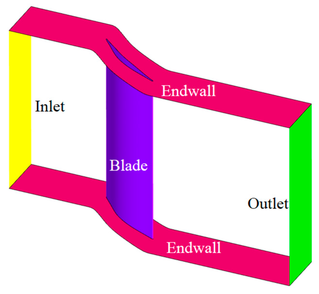
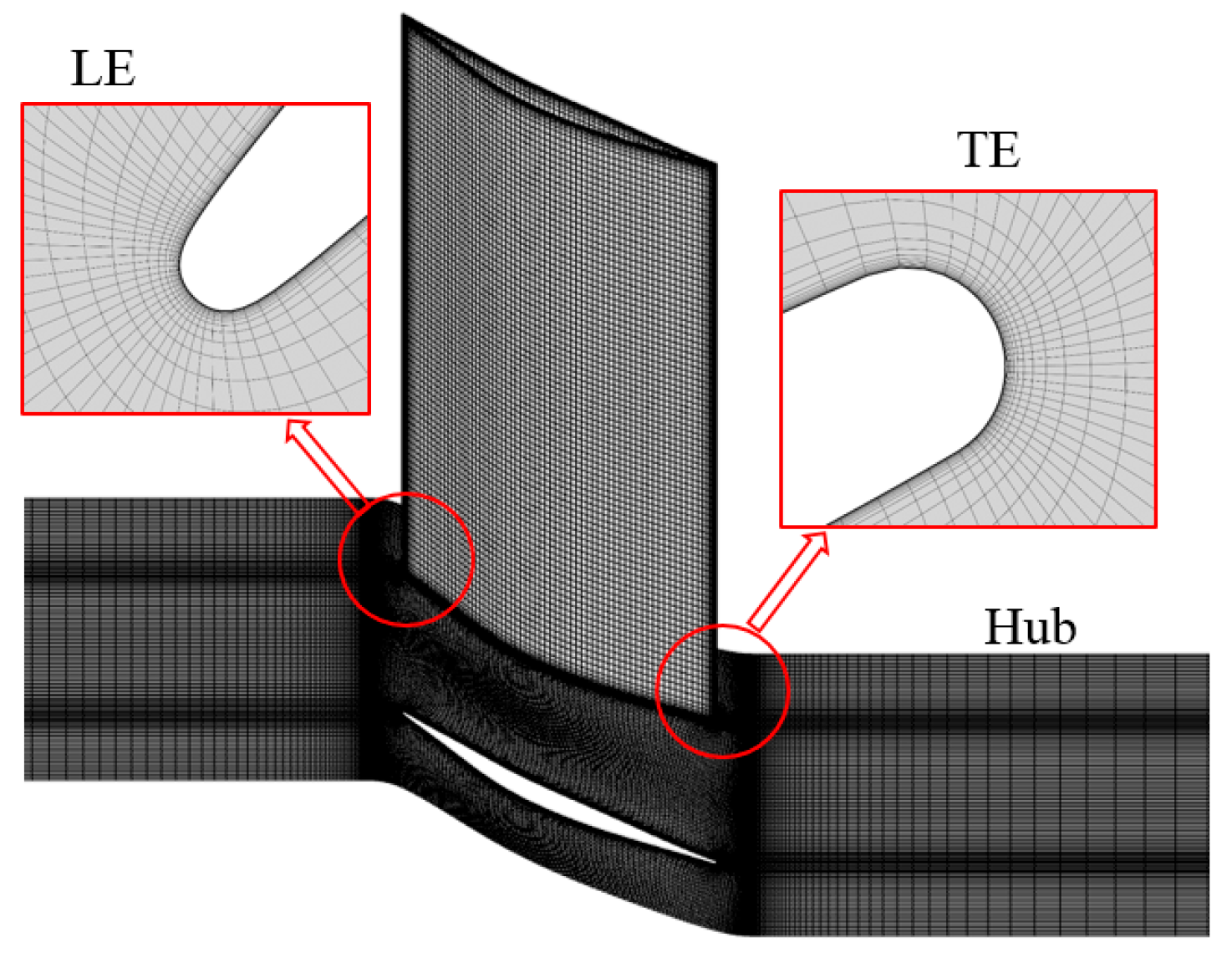
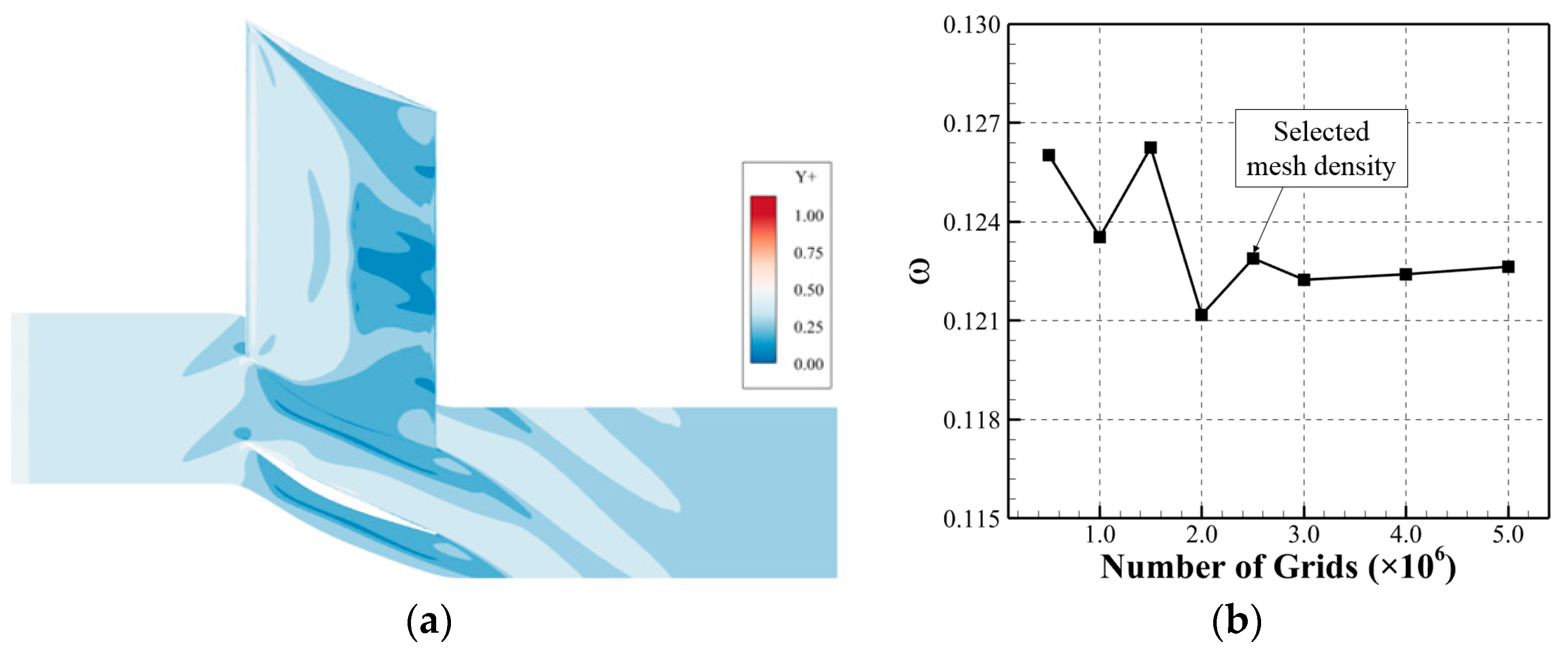
2. Geometrical and Aerodynamic Parameters

A particular supersonic compressor cascade was designed to investigate the effect of a VG on flow separation with a shock wave. The detailed geometry of the supersonic compressor is shown in Figure 1, while its geometric and aerodynamic parameters are listed in Table 1. The inlet Mach number is 1.05.

3. Geometrical and Aerodynamic Parameters

The numerical simulations were carried out based on the concept of a periodic flow field. Therefore, a single blade passage was adopted as the computational domain, as shown in Figure 2, and a translational periodic boundary condition was used for simplification. The inlet surface was located at −130% of the axial chord, while the outlet surface was located at 300% of the axial chord.
A structured mesh was created for the supersonic compressor cascade, as shown in Figure 3. The meshes near the blade leading edge (LE) and trailing edge (TE) are also shown in enlarged views. To capture the fine details of the flow field near the wall surface, the mesh near the wall surface (blade and endwall) was refined. An O-type mesh was also used around the blade surface to improve mesh quality. For this structural mesh, the Y+ value near the wall surface, shown in Figure 4a, was around 1 and met the requirements of the numerical method adopted in this study.
Steady simulations were employed by using a three-dimensional (3D) RANS solver. The SST k-ω model was selected to model turbulence. Total pressure, total temperature and velocity angle were specified at the inlet surface, while the average static pressure was presented at the outlet surface. No-slip wall conditions were presented for the blade and endwall surfaces.
In this study, a computational fluid dynamics (CFD) solver employing three-dimensional (3D) Reynolds-averaged Navier–Stokes (RANS) equations was utilized to perform a steady simulation.
The governing equations are as follows:
Conservation of mass:
ρ t + ρ V = 0 ,
Conservation of momentum:
ρ d V d t = p + τ i j + ρ R ,
Conservation of energy:
ρ d e d t + p V = λ T + V τ i j + ρ q ,
The viscous stress tensor τ i j is defined as
τ i j = μ + μ t V + V T 2 3 V ,
where μ is the dynamic viscosity and μt is the turbulent viscosity. T is the static temperature. λ is the heat conduction coefficient, which is defined by Equation (5), where Cp is the specific heat at constant pressure, Pr is the Prandtl number, and Prt is the turbulent Prandtl number.
λ = C p ( μ Pr + μ t Pr t ) ,
The system is closed using an equation of state:
p = ρ R T ,
The total pressure coefficient is defined as follows:
ω = P t 1 P t 2 P t 1 P 1 ,
where ω represents the total pressure loss coefficient, Pt1 is the total pressure at the inlet, P1 is the static pressure at the inlet, and Pt2 is the total pressure at the outlet (the axial section 50% downstream from the blade TE). Note that in Figure 8b and the subsequent loss coefficient contours, Pt2 corresponds to the local total pressure. From the mesh independence analysis shown in Figure 4b, it can be concluded that the total pressure loss coefficient exhibited minimal changes beyond a mesh size of 2.5 million, and therefore this mesh size was selected.
The numerically simulated shock wave structure for the supersonic compressor cascade was compared with the experimental results in Figure 5 (with an inlet Mach number of 1.05), where it can be seen that the two structures were exactly the same. This successfully validated the numerical model. The experiment was conducted by the author’s research group.

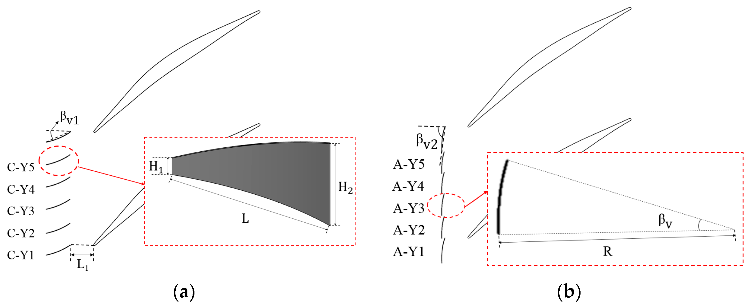
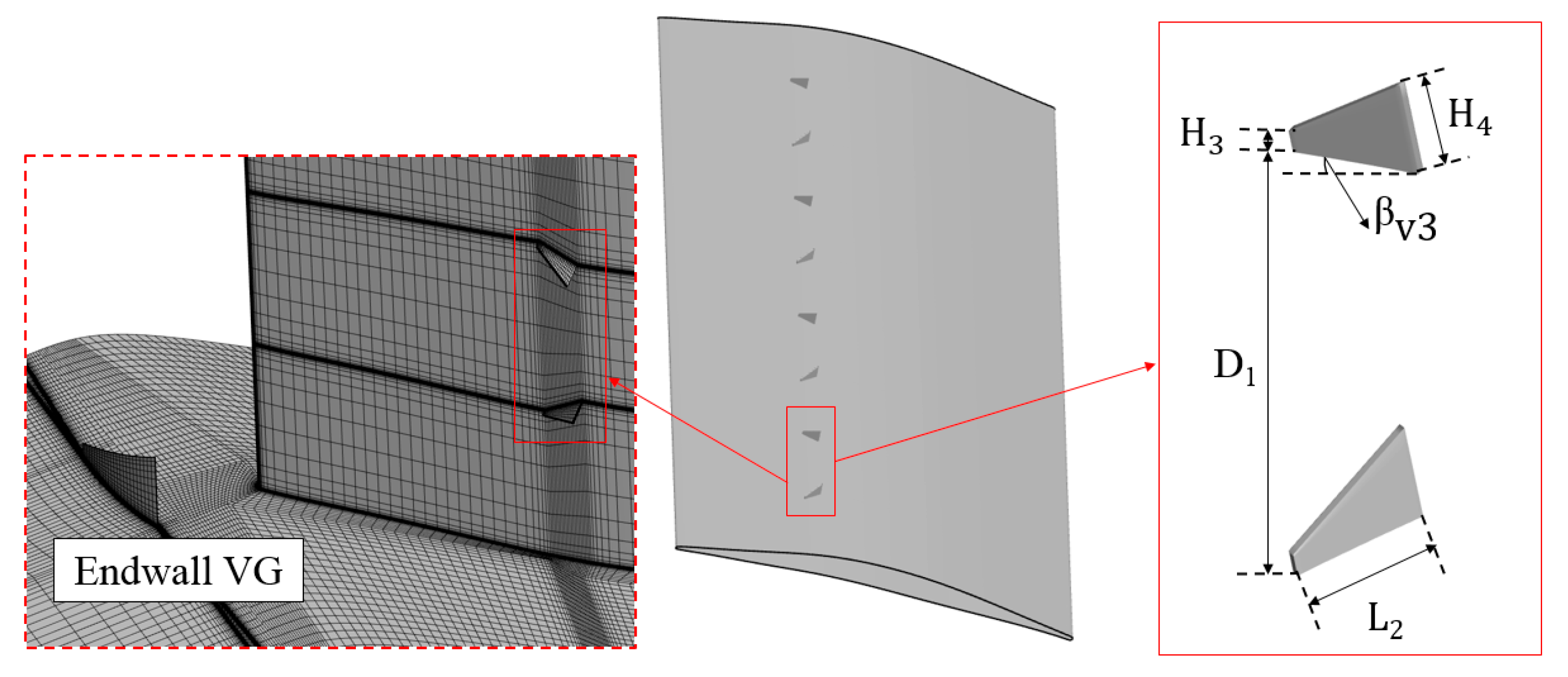
4. Design of Vortex Generator

To reduce corner separation in the supersonic compressor cascade, two types of VGs were designed to be added to either the endwall or the suction surface. The design method for the VGs and their flow fields was investigated in Ref. [29]. The two different VG designs are shown in Figure 6 and Figure 7, respectively. Because the corner separation in the supersonic compressor cascade is much more severe than the boundary-layer separation, the dimensions of the endwall VG (EVG) were larger than those of the suction surface VG (SVG). The detailed geometrical parameters of the two types of VGs are listed in Table 2. The VGs shown in Figure 6a,b can induce vortices rotating in different directions. The vortices induced by the EVG shown in Figure 6a are clockwise and denoted as “C”, while those induced by the EVG shown in Figure 6b are anticlockwise and denoted as “A”. A structured mesh for the compressor cascade with VGs was also created, which is also shown in Figure 7, with mesh refinement near VGs.
The cross-section of the EVG was a part of a circle, which proved to be an effective geometry for generating suitable vortices [29], and the radius of curvature, as shown in Figure 6b, was 21.5 mm, while the βV was 20°. The cross-section of the SVG was a line. The angle between the VG and the main flow was, in both cases, 30°. To determine the optimal designs, five different pitchwise locations were investigated for the EVGs. The distance between two EVGs was 1/5 of the pitch of the supersonic compressor cascade. The EVGs were denoted as Y1, Y2, Y3, Y4, and Y5, respectively. For SVGs, eight VGs were set on the suction surface, located at 30% of the axial chord. The distance between the leading edges of two SVGs was 1/8 of the blade height. The design employing SVGs was denoted as “S-VOR”, while that with coupled C-Y1 and SVGs was denoted as “S-C-Y1”.

5. Effect of Vortex Generator on the Corner Separation of the Supersonic Compressor Cascade

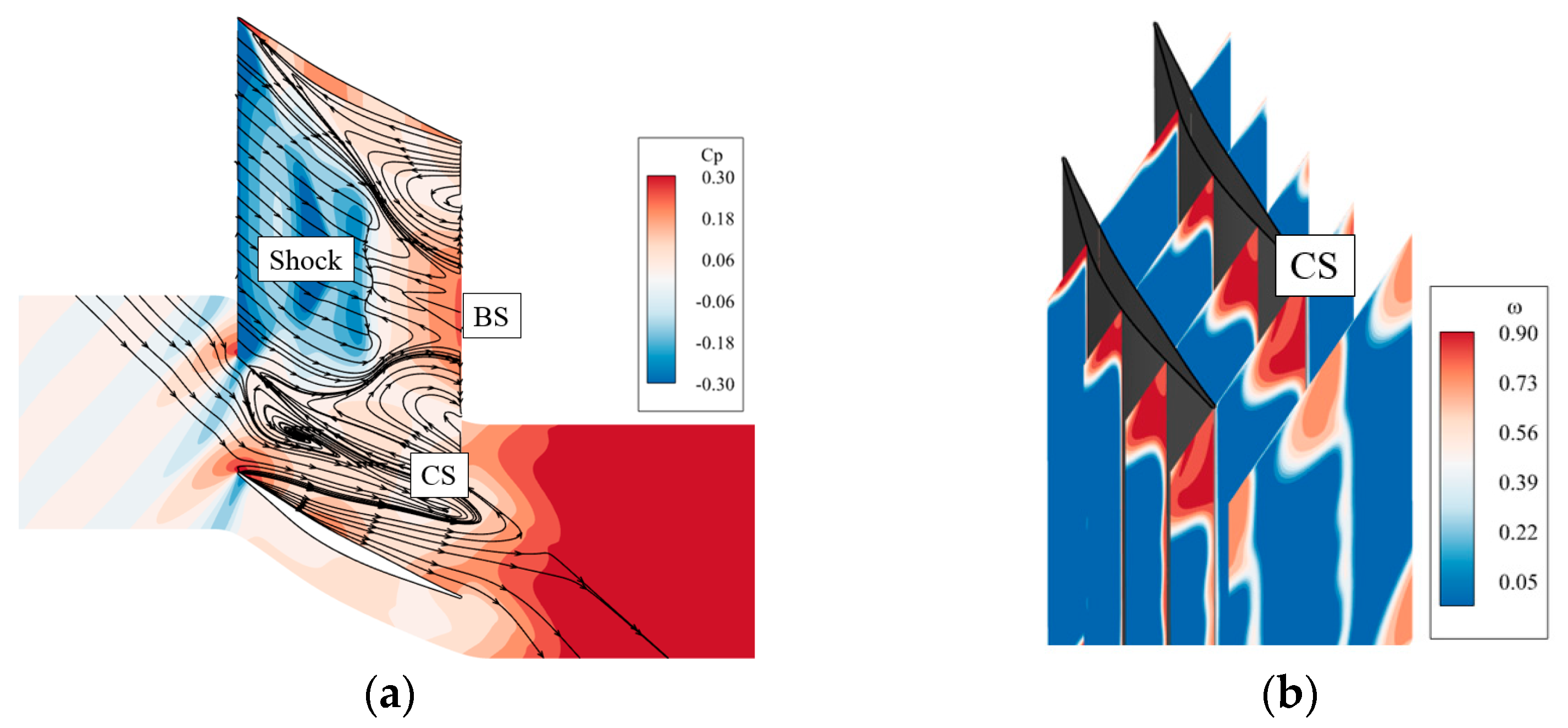
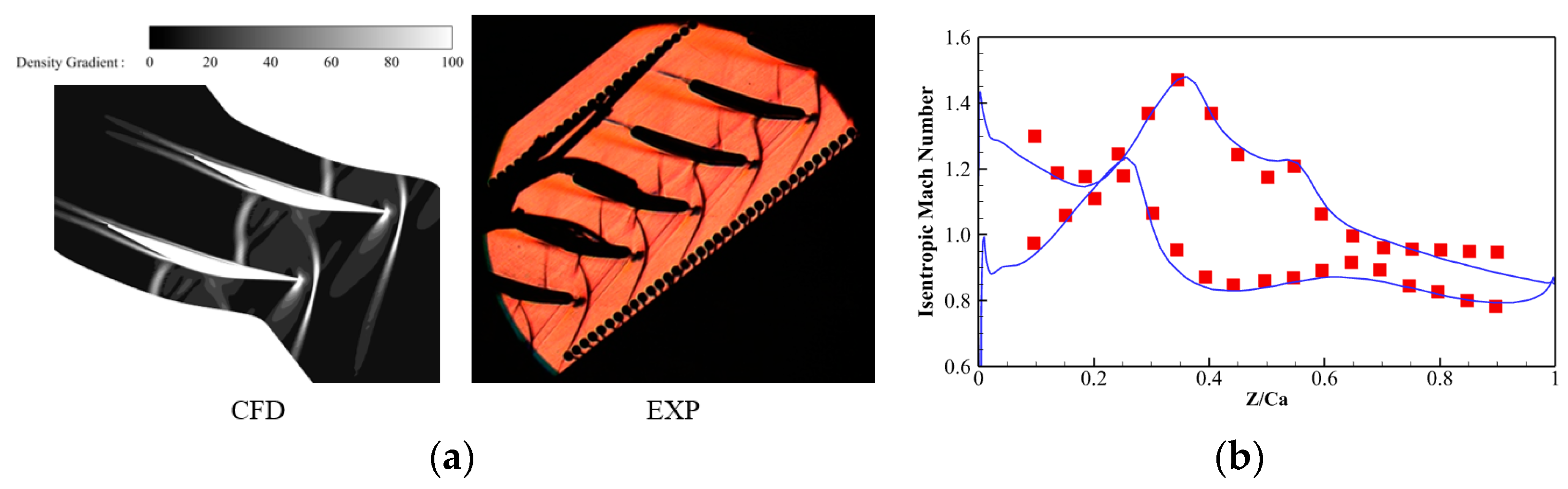
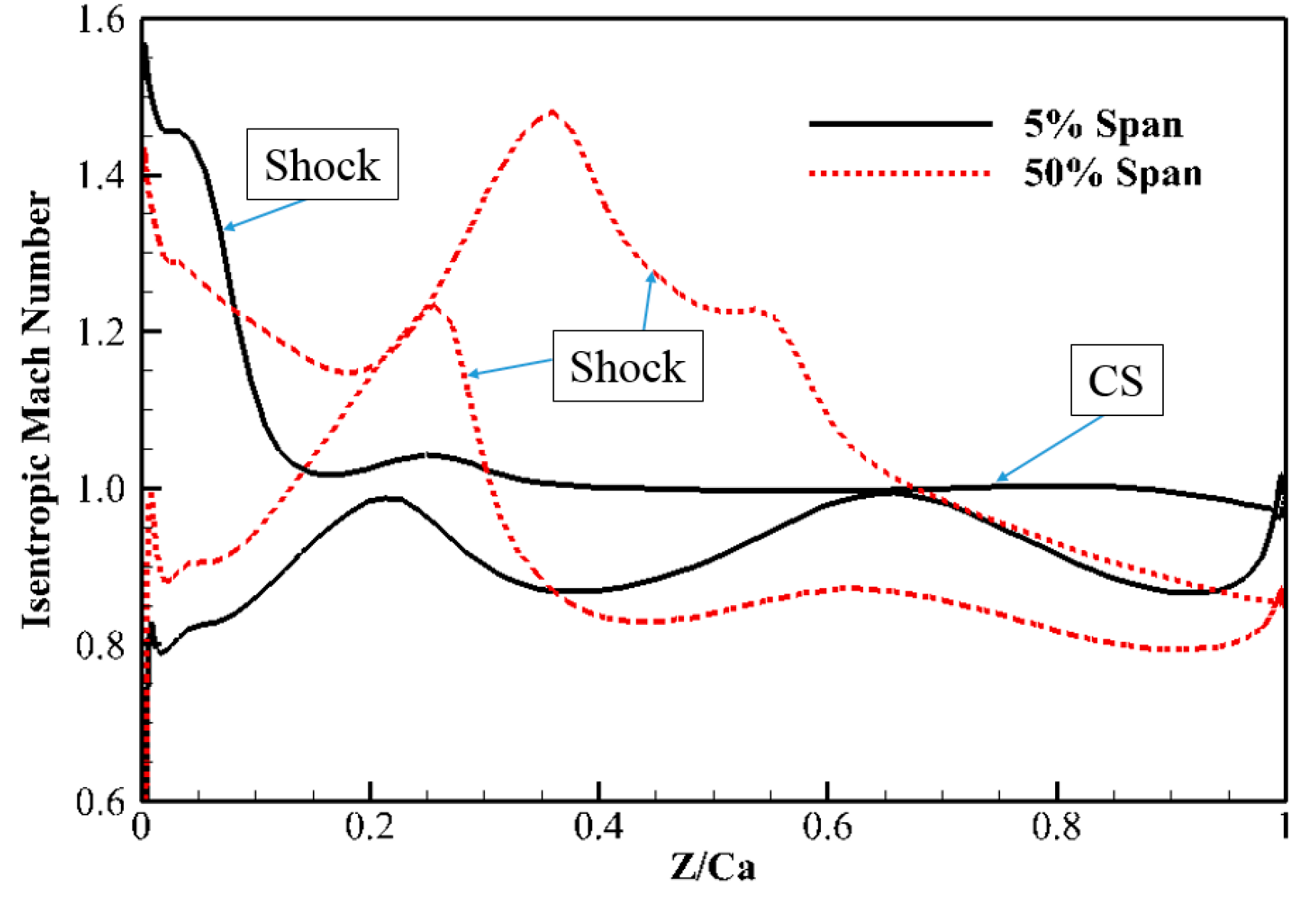
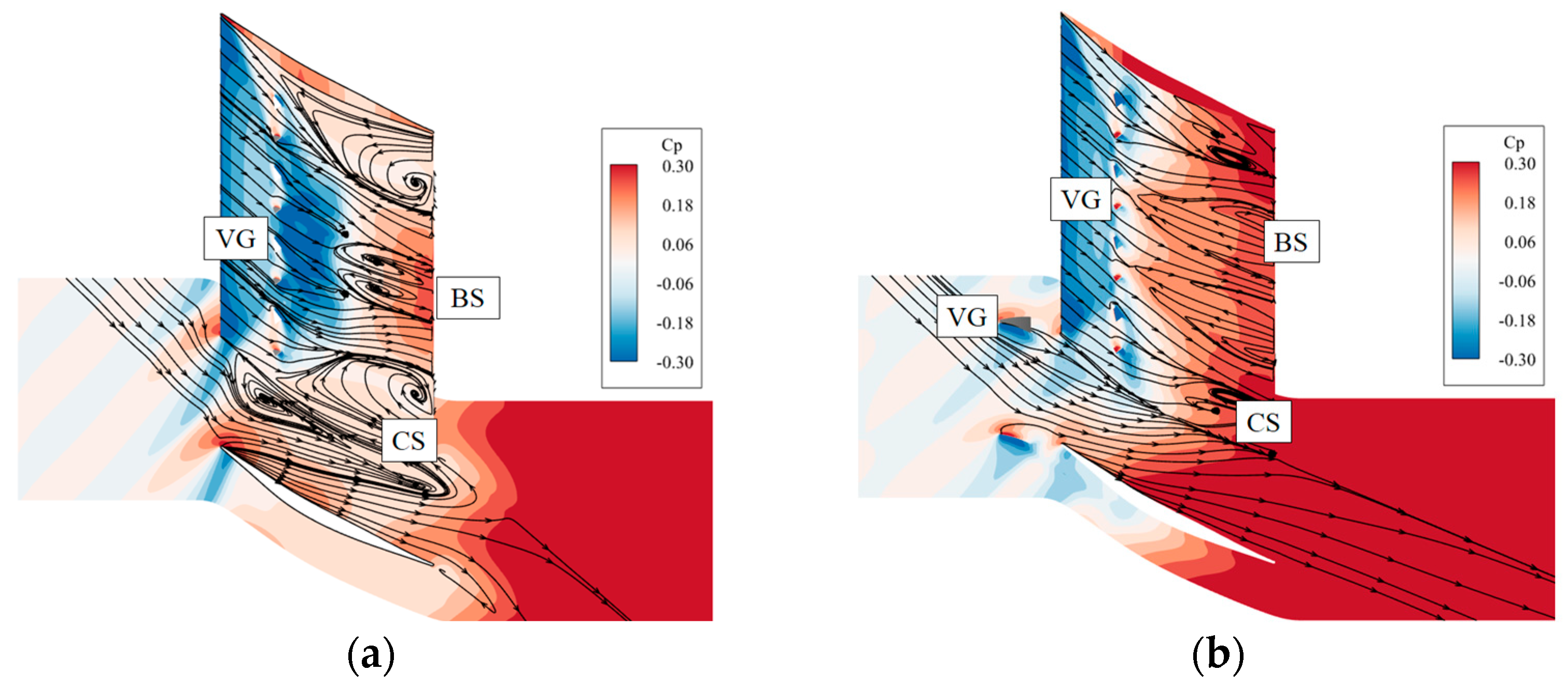
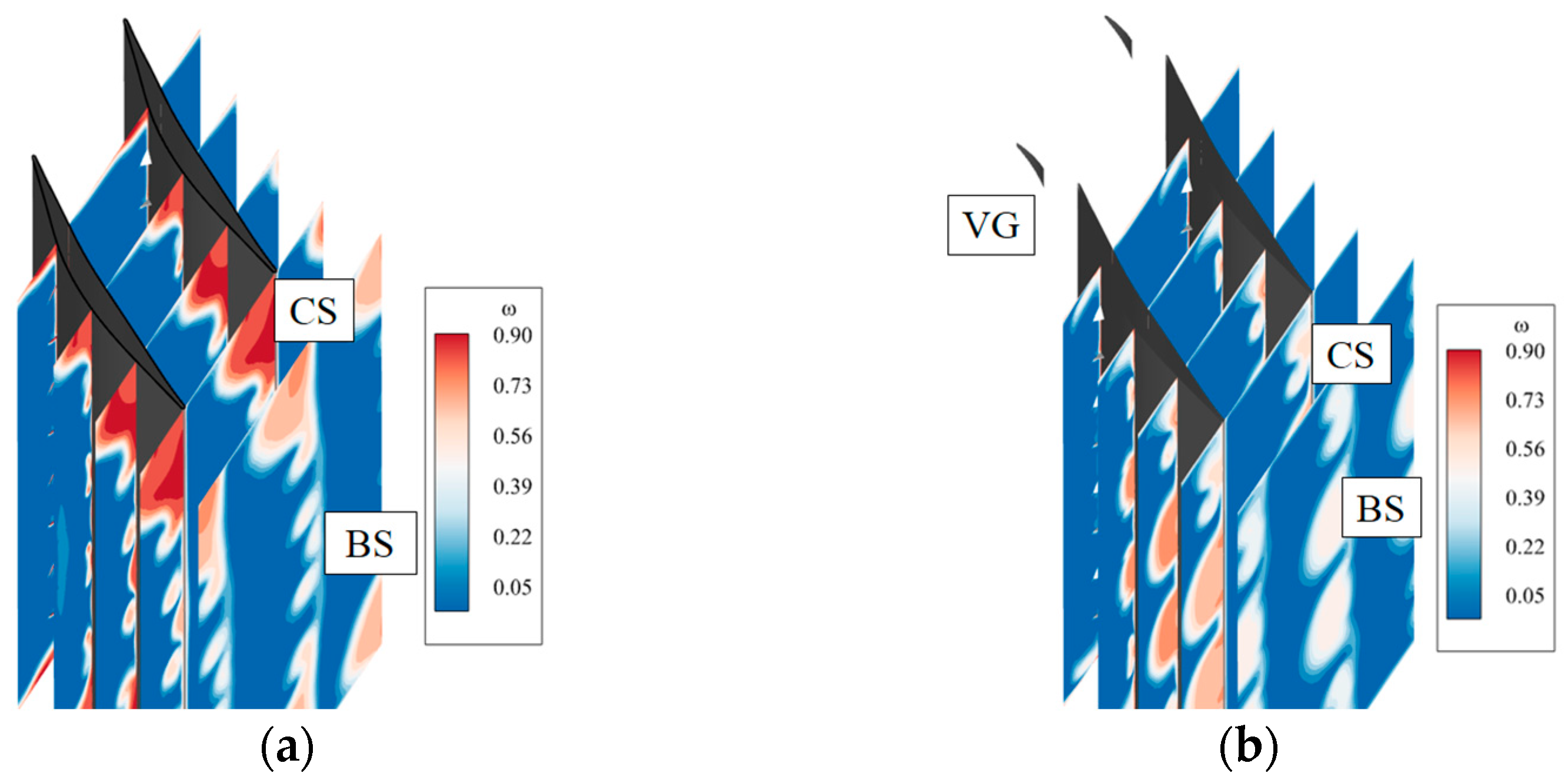
5.1. Flow Fields of Baseline Supersonic Compressor Cascade

The flow field of the baseline supersonic compressor cascade was first investigated. The static pressure coefficient, Cp, was defined as follows:
C p = ( P P 1 ) 1 2 ρ 1 V 1 2 ,
where P is local static pressure, ρ1 is the density at the inlet surface, and V1 is the velocity at the inlet surface. Figure 8a shows the static pressure coefficient contours and limiting streamlines on the suction surface and the endwall.
Figure 8. Flow field of the baseline compressor cascade: (a) static pressure coefficient contour and limiting streamlines at suction surface and endwall; (b) loss coefficient contours at different axial sections.
Aerospace 12 00692 g008
From limiting streamlines, it can be deduced that there was a severe reversed flow at the endwall/suction surface corner, indicating that corner separation occurred inside the blade passage of the supersonic compressor cascade [14]. At mid-span, reversed flow also occurred near the TE of the compressor cascade, revealing that boundary-layer separation occurred. In connection with the Cp distribution, it can be concluded that the reversed flow developed just behind the shock wave, evident not only at mid-span but also near the endwall. This indicates that the flow separation was caused by the severe adverse pressure gradient produced by the shock wave. Hence, the shock wave was the main reason for the corner and boundary-layer separations in the supersonic compressor cascade.
The loss coefficients at different axial sections of the baseline supersonic compressor cascade are shown in Figure 8b. It can be seen that the high-loss region was co-located with the corner separation. The high-loss region at mid-span was much smaller than that near the endwall. This demonstrates that corner separation is the main reason behind the losses in the supersonic compressor cascade. Therefore, to reduce losses and improve the performance of the supersonic compressor cascade, it is necessary to control corner separation.
Figure 9 shows the isentropic Mach number distributions at mid-span (50% span) and near the endwall (5% span). At mid-span, a shock is located at about 40% of the axial chord on the suction surface. At the pressure surface, a shock can also be seen, indicating that a passage shock wave occurs within the blade passage. Flow separation is unclear at mid-span. However, at 5% span, corner separation extends from about 20% to 100% of the axial chord. Compared to mid-span, the shock wave at 5% span was located upstream, and the strength of the shock wave near the endwall was larger than that at mid-span. Moreover, corner separation was located just behind the shock wave, which agreed with the conclusions drawn from Figure 8a that the shock was the main reason for the corner separation.
From the analyses presented in this section, it can be concluded that both corner separation and boundary separation were promoted by the interaction between the shock wave and boundary layer. Corner separation was the main reason for the losses in the supersonic compressor. Therefore, different VG designs are proposed in the following sections to control corner separation and improve the performance of the supersonic compressor cascade.

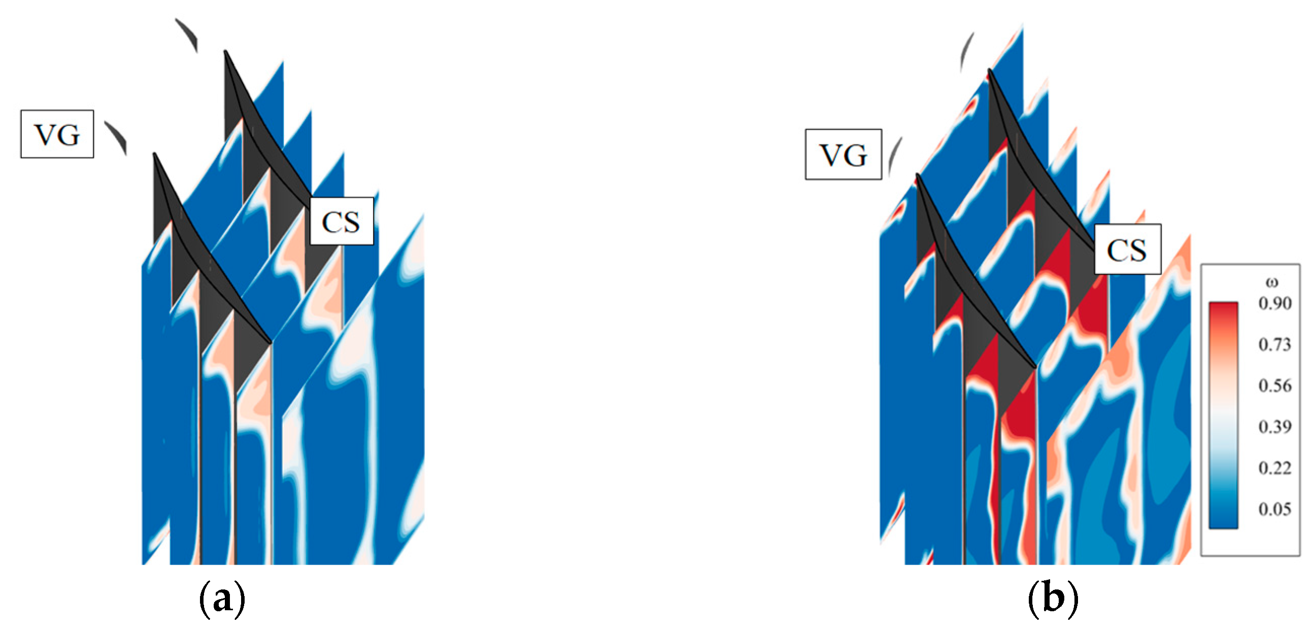
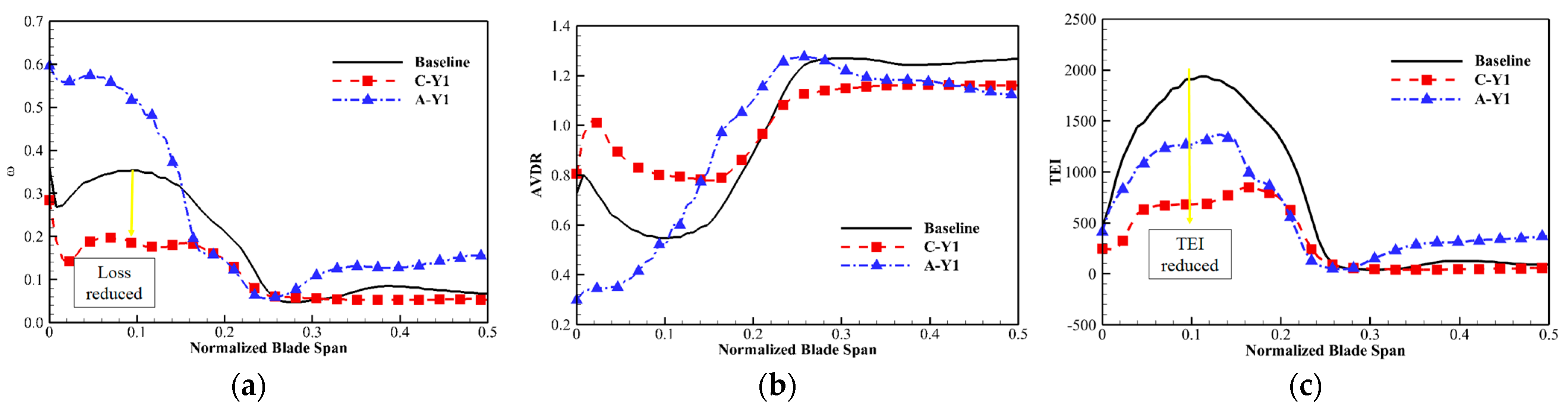
5.2. Effect of Endwall Vortex Generator on the Flow Field of the Supersonic Compressor Cascade

The EVG was demonstrated to be an effective way of controlling corner separation in a subsonic compressor cascade [28,29]. In this section, different EVG schemes were tried to investigate the effect of EVGs on the corner separation in a supersonic compressor cascade. A comparison of loss coefficients for different EVG schemes is shown in Figure 10a. In the figure, “C” refers to the schemes producing clockwise vortices, while I52 means that the inlet flow angle was 52°. It can be seen that scheme C-I52 reduced the total pressure loss coefficients at all pitchwise positions. The optimal scheme was C-Y1, which reduced losses by 24.6% compared to the baseline compressor cascade. However, the losses in scheme A-I52 increased, indicating that it was not suitable for controlling flow separation in the supersonic compressor cascade. Thus, scheme C-Y1 was selected for further investigations.
Figure 10b shows a comparison of the loss coefficients between the baseline supersonic compressor cascade and that with scheme C-Y1 with different inflow angles. It can be seen that scheme C-Y1 reduces the loss coefficients for different inlet flow angles. For the baseline cascade, the loss coefficient increases with the increase in inlet flow angle. However, for scheme C-Y1, it was first reduced and then increased with the increase in inlet flow angle. The loss coefficient reached its minimum at an inlet flow angle of 52°. The results also demonstrate that the EVG is an effective way to reduce the loss coefficient in a supersonic compressor cascade. The mechanism of the reduction in the loss coefficient is explained in the following sections.
Figure 11 shows the change in the loss coefficient after utilizing an EVG compared to the baseline cascade. The high-loss region and the values of the loss coefficient of scheme C-Y1 were reduced significantly at different axial positions, indicating that utilizing the EVG can reduce losses due to corner separation. For scheme A-Y1, the high-loss region of corner separation was reduced, indicating that even this scheme reduced the corner separation. However, a new loss region appeared because of the vortices induced by the EVGs. As a result, the total loss coefficient of scheme A-Y1 increased. Moreover, the loss coefficient at mid-span for scheme A-Y1 also increased.
Schemes C-Y1 and A-Y1 were compared with the baseline supersonic compressor cascade to reveal the mechanism of the EVG’s effect on corner separation. Figure 12 shows the static pressure coefficient contours and limiting streamlines on the suction surface and endwall for different EVG schemes. From the limiting streamlines of scheme C-Y1 in Figure 12a, it can be concluded that the onset of reversed flow at the corner region was significantly delayed. Moreover, the reversed flow at the endwall nearly disappeared. These observations indicate that scheme C-Y1 reduced corner separation. Compared to the baseline cascade, the reversed flow disappeared at mid-span, indicating that boundary-layer flow separation was also reduced. From the Cp distribution, it can be concluded that the static pressure increased after utilizing the EVG, indicating that after the reduction in corner separation, the diffusion capacity of the supersonic compressor cascade increased. Because of the increase in static pressure at the TE, the shock waves near mid-span shifted upstream and the interaction between the shock waves and boundary layer reduced. As a result, the boundary-layer separation at mid-span declined.
In Figure 12b, it can be seen that corner separation still existed. Compared to the baseline cascade, the onset of corner separation was also delayed. However, the reversed flow region near the hub expanded. These results indicate that scheme A-Y1 delayed corner separation, but the boundary-layer separation at mid-span barely changed. Although corner separation was delayed, the loss coefficient of the compressor cascade increased. A comparison of the Cp distributions demonstrates that the use of the EVG changed the shock wave structure near the hub, which may be one of the reasons for the changes in the flow field.
To explore the effect of the EVG on the shock wave structure, the Mach number distributions and a comparison of the isentropic Mach number distributions at different blade positions are shown in Figure 13 and Figure 14, separately. In Figure 13a, two shocks at 5% span in the baseline cascade can be seen: one of them is extended ahead of the blade LE, whereas the other is a channel shock wave. After the channel shock, there was a low-momentum region, which resulted from corner separation. In Figure 13b, compared to the baseline cascade, the low-momentum region of scheme C-Y1 was reduced. Moreover, the shock was affected by the EVG and vortices it induced. It can be seen that the EVG separated the extended shock wave and it regenerated on its own surface. However, the strength of the shock wave barely changed. The EVG scheme A-Y1 enhanced the extended shock. Inside the blade passage, the channel shock wave was also separated by the vortices induced by the EVG, which were also affected by the shock wave. Figure 13c indicates that the momentum of the induced vortices was significantly smaller after the shock. Hence, a new loss was induced by the vortices. From Figure 13, it can be concluded that the structure of EVG had a significant effect on the structure of the shock wave and that scheme C-Y1 was suitable for the supersonic compressor cascade.
Figure 14 shows a comparison of isentropic Mach number distributions at different blade positions. At the blade mid-span, the shock wave evidently changed after utilizing the EVG. The shock in the baseline cascade was located at about 40% of the axial chord, but after utilizing the EVG in scheme C-Y1, corner separation was reduced, causing an increment in static pressure at the TE of the supersonic compressor cascade. As a result, the channel shock wave moved upstream and its strength was reduced. Hence, the boundary-layer separation caused by the interaction between the boundary layer and the shock diminished, resulting in a reduction in losses at the blade mid-span. For scheme A-Y1, the shock wave moved downstream and its strength increased. This was due to the reduced static pressure at the TE causing an increase in shock wave strength. At 5% span, the strength of the shock wave of cascades C-Y1 and A-Y1 was reduced because of the effect of the EVGs. As a result, the onset of corner separation was delayed.
Figure 15a shows the loss coefficient distribution along the blade span at 150% of the axial chord. Coupled with the flow field above, it can be concluded that the high-loss region in the baseline cascade was located between 0 and 25% of the blade span. After utilizing the EVG in scheme C-Y1, the endwall losses reduced significantly. However, even though the corner separation in scheme A-Y1 was reduced, the losses between 0 and about 15% of the blade span increased, which was caused by the EVG. At mid-span, the losses of scheme C-Y1 barely changed, while those of scheme A-Y1 increased.
To better describe the mechanism of the EVG’s action on the flow field in the supersonic compressor cascade, the AVDR is defined as follows:
A V D R = ρ 2 V z 2 ρ 1 V z 1 ,
where ρ1 and Vz1 are the density and axial velocity at the cascade inlet and ρ2 and Vz2 are the density and axial velocity at 150% of the axial chord.
The AVDR distribution along the blade span at 150% of the axial chord is shown in Figure 15b. The suppression of corner separation by scheme C-Y1 was demonstrated by increasing the AVDR from 0 to about 20% of the blade span. At mid-span, the AVDR declined because of the suppressed corner separation. However, suppressing the boundary-layer separation increased the AVDR of the compressor cascade. Hence, the AVDR had little effect on the boundary-layer separation at mid-span, and its reduction was due to the smaller interactions between the shock waves and boundary layer. For scheme A-Y1, the reduction in AVDR confirmed the increased flow separation. The AVDR from about 10% to 27% of the axial chord increased, indicating that scheme A-Y1 reduced corner separation. The turbulence kinetic energy (TEI) distribution along the blade span at 150% of the axial chord is shown in Figure 15c. At baseline, the TEI is largest from 0 to 0.25 in relation to blade span, which is a result of corner separation. By utilizing scheme C-Y1 and scheme A-Y1, the TEIs are both reduced due to the effect of the endwall vortex.

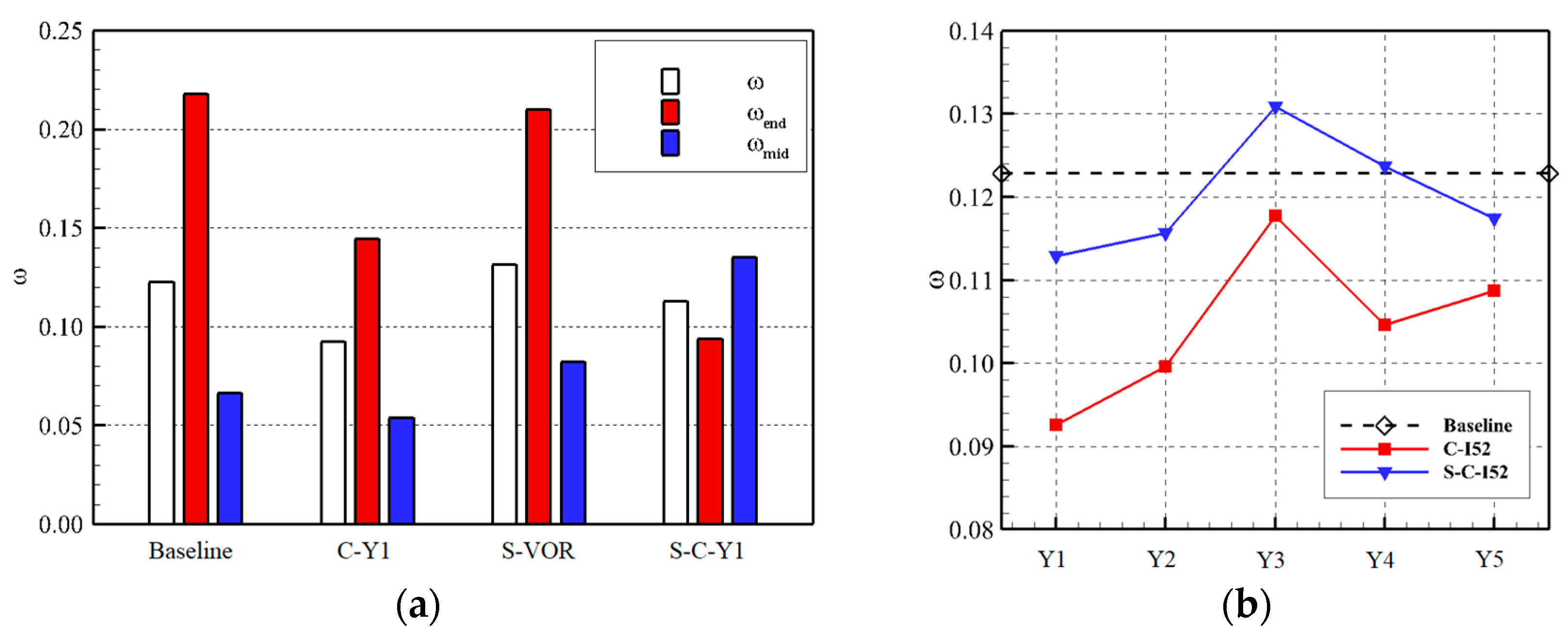
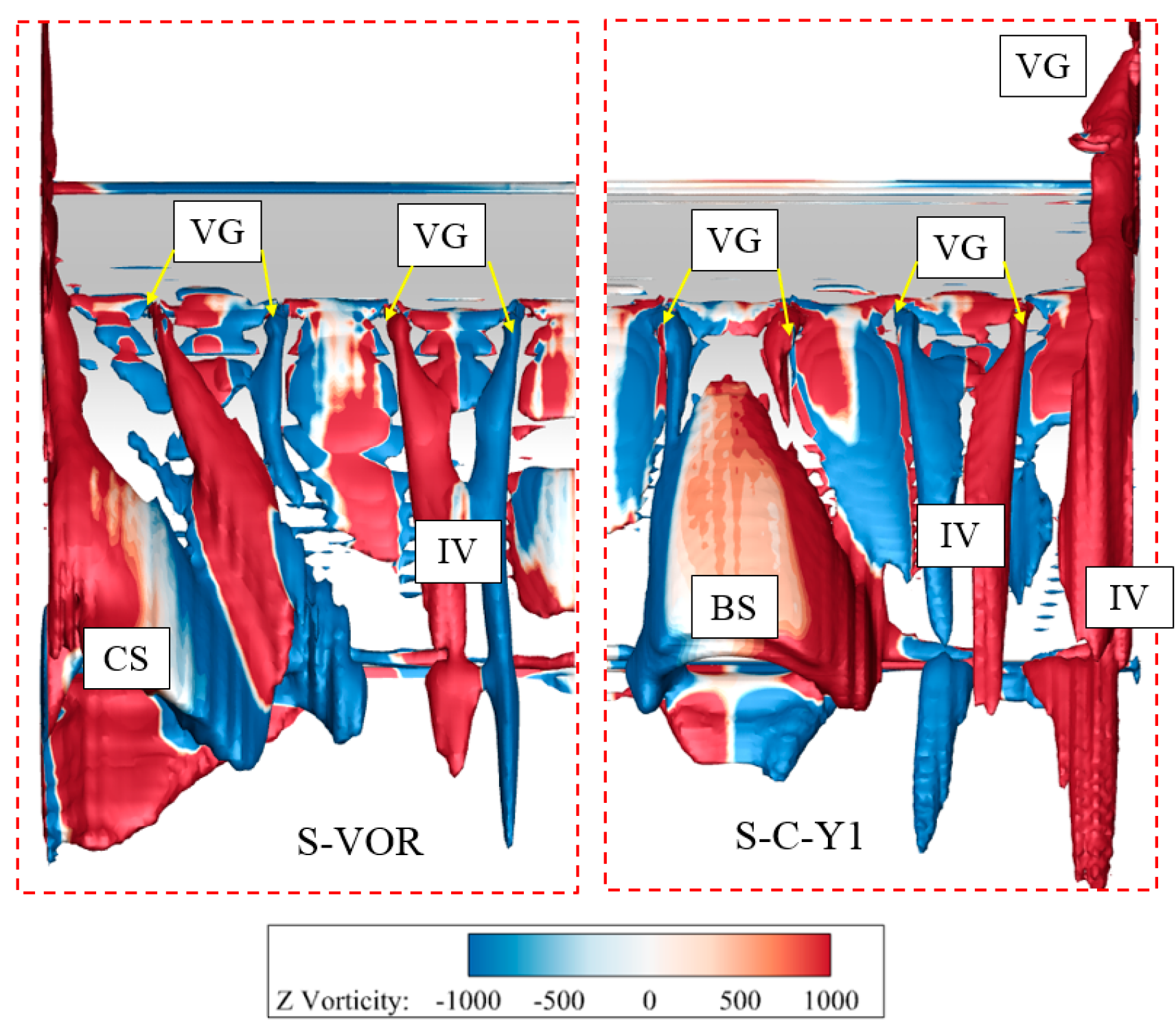
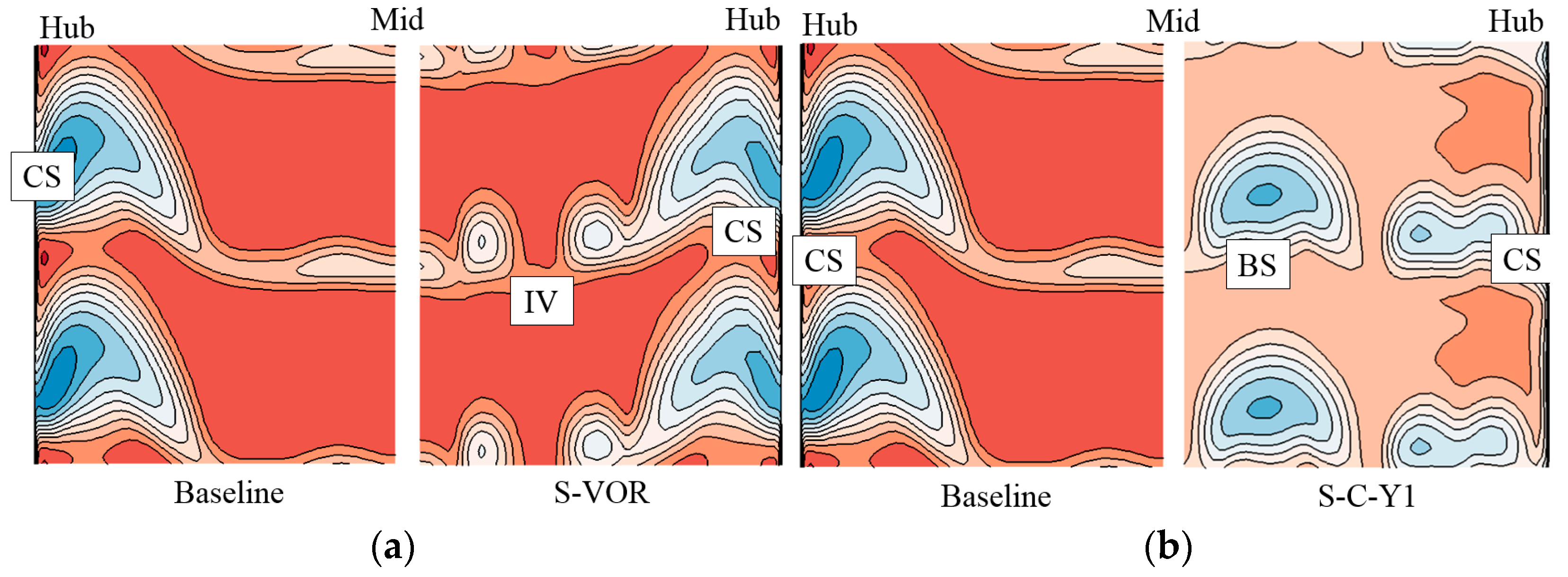
5.3. Effect of Endwall Vortex Generator Coupled with Suction Surface Vortex Generators on the Flow Field of the Supersonic Compressor Cascade

Corner separation results from secondary flow near the endwall and boundary-layer separation on the suction surface [11]. To further reduce the corner separation in the supersonic compressor, a coupled E-SVG was designed and its performance was simulated. The endwall loss (ωend) and mid-span loss (ωmid) were defined as follows:
ω e n d = P t 1 P t 2 ( 0 % 25 % ) P t 1 P 1 ,
ω m i d = P t 1 P t 2 ( 25 % 75 % ) P t 1 P 1
where Pt2(0%–25%) is the mass-weighted average value of the total pressure from 0% to 25% of the blade span and Pt2(25%–75%) is the mass-weighted average value of the total pressure from 25% to 75% of the blade span.
The loss coefficients are compared in Figure 16a. It can be seen that scheme C-Y1 achieved the minimum total pressure loss coefficient, which was reduced by 24.6% compared to the baseline cascade. At mid-span, scheme C-Y1 also achieved a minimum, i.e., a reduction by 18.9% compared to the baseline cascade. However, the minimum endwall loss was achieved by scheme S-C-Y1, i.e., the coupled E-SVG design. The endwall loss of this scheme was reduced by 56.9% compared to the baseline cascade, while the endwall loss using scheme C-Y1 was reduced by 33.6%. Thus, scheme S-C-Y1 had superior performance in controlling corner separation compared to schemes that utilized either EVGs or an SVG only. The separation suppression mechanism is discussed in the following section.
The loss coefficients of the supersonic compressor cascade with different suction schemes are shown in Figure 16b. The loss coefficient of scheme S-C-I52 was higher than that of C-I52. However, the trends of the changes in the loss coefficient with the changing pitchwise location of the EVG were the same for the two schemes. The minimum loss coefficients were achieved at location Y1 for both schemes. The minimum loss of scheme S-C-I52 was reduced by 8.2% compared to the baseline cascade.
Figure 17 shows the static pressure coefficient contours and limiting streamlines on the suction surface and the endwall. Compared to the baseline cascade, the spanwise region of the corner separation of scheme S-VOR was reduced. Moreover, the reversed flow region at mid-span was also reduced, indicating that the SVGs suppressed corner and boundary-layer separations. The mechanism behind these changes was that vortices produced by the VG increased the momentum transfer between the boundary layer and the main stream [19]. As shown in Figure 17b, the reversed flow region near the blade suction surface of scheme S-C-Y1 increased compared to the baseline cascade. However, the corner separation was reduced significantly. Compared to scheme C-Y1, the corner separation region of scheme S-C-Y1 was much smaller, indicating that the coupled E-SVG further reduced the corner separation.
The distribution of Cp shown in Figure 17 and that of the isentropic Mach number shown in Figure 18 demonstrate that for scheme S-C-Y1, the shock strength near LE was reduced compared to the other schemes. From about 10% to 35% of the axial chord, the isentropic Mach number increased due to the effect of the SVG, and at about 40% of the axial chord, there was a new shock wave. Hence, the adverse pressure gradient was reduced, which is beneficial for controlling corner separation.
Figure 19 shows the loss coefficient distribution at different axial positions. Compared to the baseline cascade, the corner separation of scheme S-VOR barely changed, indicating that the suction vortices had little effect on corner separation. However, the high-loss region of scheme S-C-Y1 reduced significantly, indicating that the coupled E-SVG exerted a superior controlling effect on corner separation. At mid-span, there were three high-loss regions for scheme S-VOR, caused by vortices which were induced by the SVGs. As for scheme S-C-Y1, the high-loss region near mid-span increased significantly. The existing literature points out that the structures of vortices and the boundary layer are highly influenced by adverse pressure gradients [19]. After the reduction in corner separation by scheme S-C-Y1, the static pressure at the TE of the compressor cascade increased, causing an increase in the adverse pressure gradient. As a result, vortices at the suction surface were distorted and losses near mid-span increased.
The loss coefficient, AVDR, and TEI distributions are shown in Figure 20. In Figure 20a, it can be seen that, compared to the baseline cascade, the losses in scheme S-VOR from 0 to 25% of the span hardly changed, indicating that the SVG had little effect on corner separation in this scheme. The losses in scheme C-Y1 were reduced. However, the losses from 0 to 25% of the blade span in scheme S-C-Y1 were much lower than those in scheme C-Y1. These results indicate that the coupled E-SVG scheme exhibited superior effectiveness in controlling corner separation. However, the losses from 25% to 50% of the span in scheme S-C-Y1 were the largest because of the distortion of suction vortices. The variation in AVDR and TEI also confirmed the suppression of corner separation.
Figure 21 shows the vortex structure in schemes S-VOR and S-C-Y1, where it can be observed that utilizing only the SVG produced little effect on the flow field near the hub. As a result, corner separation still occurred for scheme S-VOR. By utilizing the EVG, high momentum was injected into the low-momentum region and corner separation was reduced. It can be seen that the corner separation of scheme S-C-Y1 was suppressed. The results demonstrate that the coupled E-SVG near the hub region better suppressed corner separation. At mid-span, counter-rotating vortex pairs of scheme S-VOR suppressed boundary-layer separation. However, severe boundary-layer separation occurred in scheme S-C-Y1. After corner separation suppression, the AVDR near the endwall increased, causing a reduction in the AVDR at mid-span (see Figure 20b). Hence, the boundary-layer separation increased.
The Mach number distributions at 150% of the axial chord are shown in Figure 22. From Figure 22a, it can be seen that, compared to the baseline cascade, the low-momentum region near the hub barely changed. At mid-span, two low-momentum regions existed after utilizing the SVG. A high loss was induced by suction vortices. However, it can also be seen that the Mach numbers in the region between two vortices increased, indicating that suction vortices have the potential to reduce boundary-layer separation. In Figure 22b, it can be seen that the low momentum near the corner region for scheme S-C-Y1 was significantly reduced compared to the baseline cascade. However, the low-momentum region near mid-span increased.

6. Conclusions

Different VG designs, namely the EVG, SVG, and combined E-SVG, were investigated to suppress corner separation in a supersonic compressor cascade and improve its performance. The main conclusions drawn from this study are as follows:
(1)
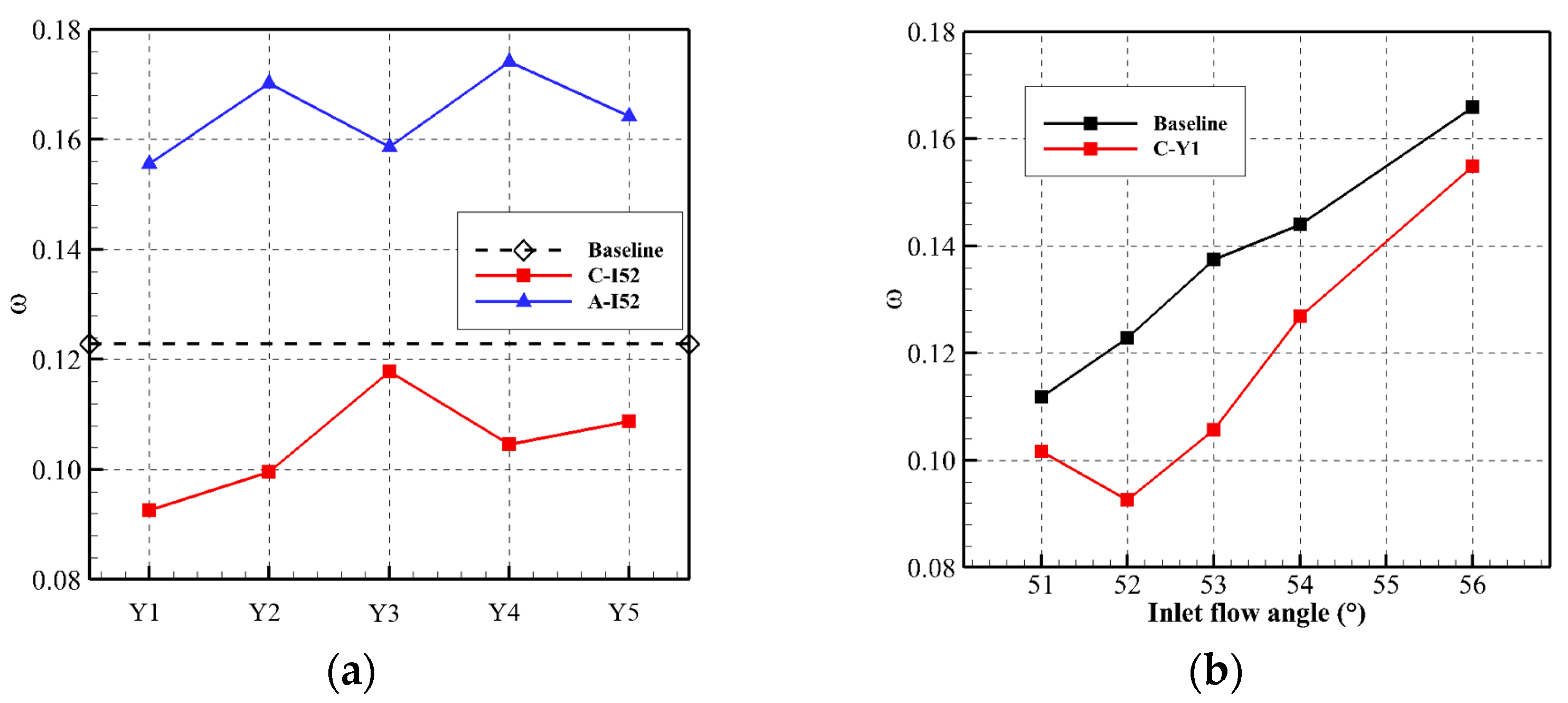
The VG significantly reduced corner separation in the supersonic compressor cascade. Total pressure losses were reduced by as much as 24.6%, while endwall losses decreased by 33.6%. The optimal EVG design placed them near the suction surface and produced clockwise vortices. The coupled E-SVG design better controlled corner separation compared to the EVG only, with the endwall losses of the coupled design reduced by up to 56.9%.
(2)
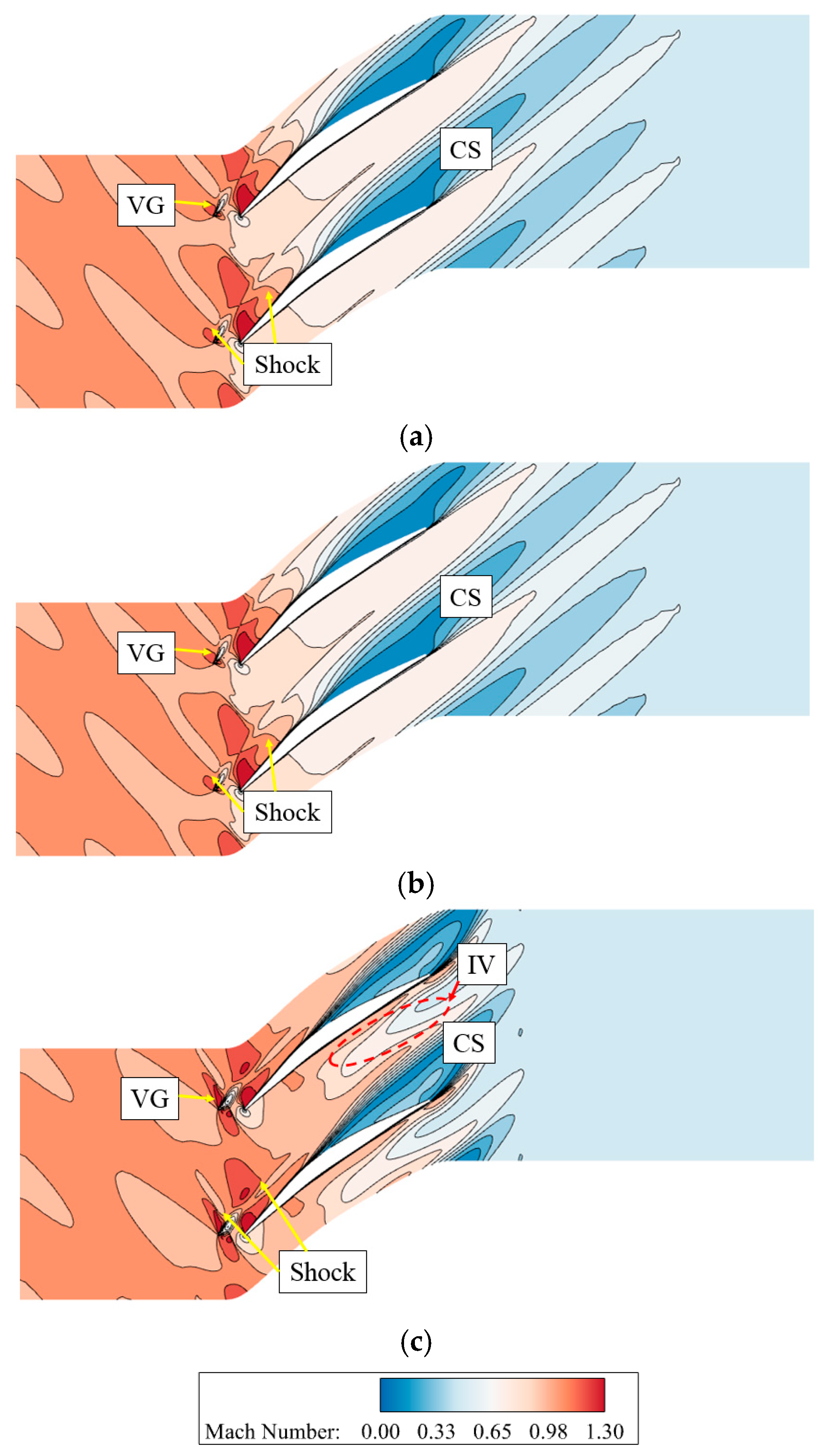
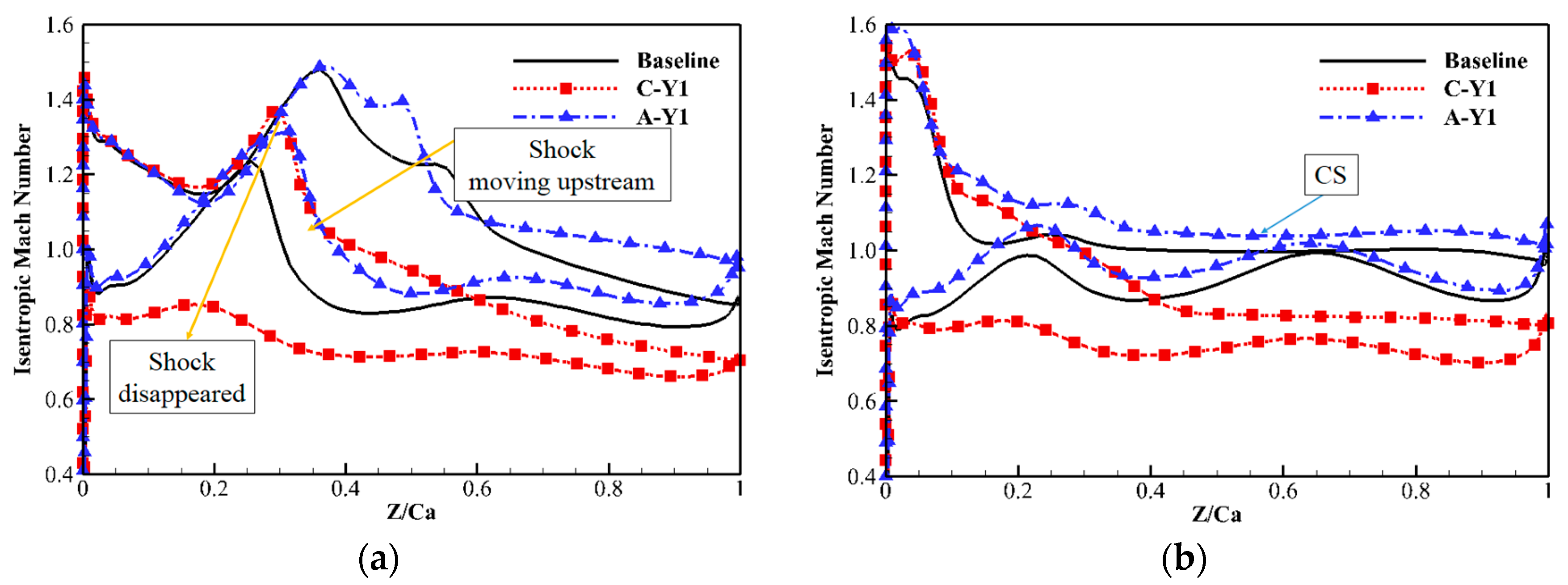
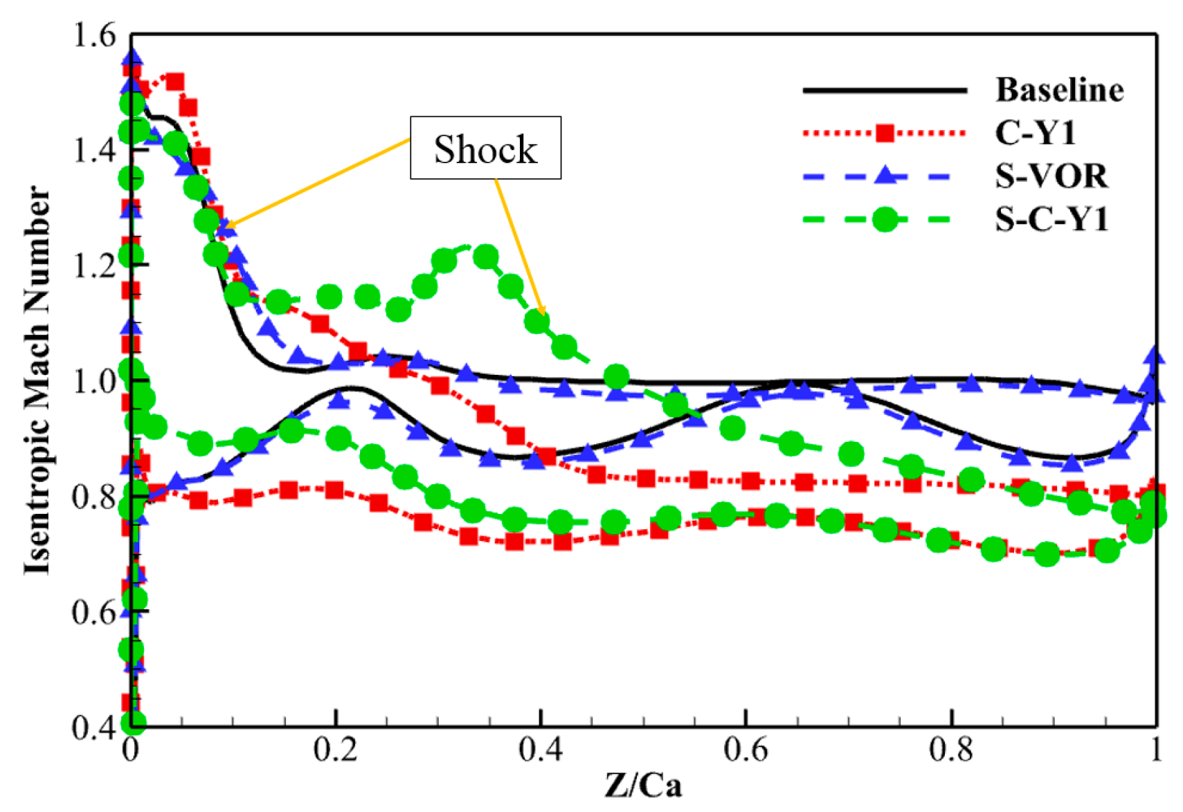
The EVG reduced corner separation by changing the direction of the separation flow. Both clockwise and anticlockwise vortices reduced the high-loss region caused by corner separation. However, anticlockwise vortices induced new losses, increasing the total pressure losses. With clockwise vortices, the VG reduced losses at all pitchwise locations. The optimal design employed a VG located near the suction surface. An analysis of the shock structure near the endwall concluded that the VG of design C-Y1 had little effect on the shock structure, which made it suitable to control corner separation in a supersonic compressor cascade.
(3)
The coupled E-SVG design also reduced the total pressure losses in the supersonic compressor cascade. However, losses at mid-span increased due to the variation in AVDR. The SVG changed the shock structure. The isentropic Mach number near the endwall was first reduced and then increased in front of the SVG, and a new shock appeared behind the SVG. The variation in shock reduced the adverse pressure gradient induced by the shock, which was also beneficial for controlling corner separation.
This investigation demonstrated that the VG can control corner separation even in a supersonic compressor cascade. The suitable shape of a VG was also determined. However, the investigation was carried out for a specific compressor blade profile and thus other blade profiles have to be investigated in future to validate the effectiveness of the VG for controlling corner separation in supersonic compressor cascades.

Author Contributions

Methodology, validation, formal analysis, investigation, data curation, writing—original draft preparation, visualization: X.G.; conceptualization, resources, writing—review and editing, funding acquisition, project administration: Z.C.; writing—review and editing: Q.G.; supervision: B.L. All authors have read and agreed to the published version of the manuscript.

Funding

This research was funded by the Innovation Foundation for Doctor Dissertation of Northwestern Polytechnical University, grant number CX2024062, the National Natural Science Foundation of China, grant number 51806174, and the National Science and Technology Major Project.

Data Availability Statement

Not applicable.

Acknowledgments

The authors would like to express their gratitude to EditSprings (https://www.editsprings.cn, accessed on 30 June 2025) for the expert linguistic services provided.

Conflicts of Interest

The authors declare no conflicts of interest.

Abbreviations

The following abbreviations are used in this manuscript:
βinInlet flow angle
βoutOutlet flow angle
βsStagger angle
ρDensity
ωTotal pressure loss coefficient
CChord of the compressor cascade
HHeight of the compressor cascade
PLocal static pressure
PtTotal pressure
tPitch of the compressor cascade
VzAxial velocity
AVDRAxial velocity density ratio
BSBoundary-layer separation
CSCorner separation
EVGEndwall vortex generator
E-SVGEndwall vortex generator coupled with suction surface vortex generator
IVVortex induced by vortex generator
LEBlade leading edge
SVGSuction surface vortex generator
TEBlade trailing edge
VGVortex generator

References

  1. Ma, Y.; Zhao, Q.; Zhang, K.; Xu, M.; Zhao, W. Analysis of Instantaneous Vibrational Energy Flow for an Aero-Engine Dual-Rotor–Support–Casing Coupling System. J. Eng. Gas. Turbines Power 2020, 142, 051011. [Google Scholar] [CrossRef]
  2. Shen, C.; Qiang, X.; Teng, J. Numerical and Experimental Investigation of an Axial Compressor Flow with Tandem Cascade. J. Therm. Sci. 2012, 21, 500–508. [Google Scholar] [CrossRef]
  3. Sun, S.; Hao, J.; Yang, J.; Zhou, L.; Ji, L. Impacts of Tandem Configurations on the Aerodynamic Performance of an Axial Supersonic Through-Flow Fan Cascade. J. Turbomach. 2022, 144, 041009. [Google Scholar] [CrossRef]
  4. Banjac, M.; Savanovic, T.; Petkovic, D.; Petrovic, M.V. A Comprehensive Analytical Shock Loss Model for Axial Compressor Cascades. J. Turbomach. 2022, 144, 091003. [Google Scholar] [CrossRef]
  5. Kusters, B.; Schreiber, H.A. Compressor Cascade Flow with Strong Shock-Wave/Boundary-Layer Interaction. AIAA J. 1998, 36, 2072–2078. [Google Scholar] [CrossRef]
  6. Prasad, A. Evolution of Upstream Propagating Shock Waves From a Transonic Compressor Rotor. J. Turbomach. 2003, 125, 133–140. [Google Scholar] [CrossRef]
  7. Li, Z.; Ju, Y.; Zhang, C. Parallel Large-Eddy Simulation of Subsonic and Transonic Flows with Transition in Compressor Cascade. J. Propuls. Power 2019, 35, 1163–1174. [Google Scholar] [CrossRef]
  8. Tweedt, D.L.; Schreiber, H.A.; Starken, H. Experimental Investigation of the Performance of a Supersonic Compressor Cascade. J. Turbomach. 1988, 110, 456–466. [Google Scholar] [CrossRef]
  9. Schreiber, H.A.; Starken, H. An investigation of a strong shock-wave turbulent boundary layer interaction in a supersonic compressor cascade. J. Turbomach. 1992, 114, 494–503. [Google Scholar] [CrossRef]
  10. Bloch, G.S.; Copenhaver, W.W.; O’Brien, W.F. A Shock loss model for supersonic compressor cascades. J. Turbomach. 1999, 121, 28–35. [Google Scholar] [CrossRef]
  11. Boudet, J.; Lévêque, E.; Touil, H. Unsteady Lattice Boltzmann Simulations of Corner Separation in a Compressor Cascade. J. Turbomach. 2022, 144, 011010. [Google Scholar] [CrossRef]
  12. Liu, Y.; Tang, Y.; Scillitoe, A.D.; Tucker, P.G. Modification of Shear Stress Transport Turbulence Model Using Helicity for Predicting Corner Separation Flow in a Linear Compressor Cascade. J. Turbomach. 2020, 142, 021004. [Google Scholar] [CrossRef]
  13. Ma, J.; Yang, G.; Zhou, L.; Ji, L.; Zhang, C. Effect of a Blade End Slot on Supersonic Compressor Cascade Hub-Corner Separation. Aerosp. Sci. Technol. 2021, 118, 107032. [Google Scholar] [CrossRef]
  14. Cao, Z.; Gao, X.; Zhang, T.; Liu, B. Flow Mechanism and Aspiration Strategies in an Ultra-Highly Loaded Supersonic Compressor Cascade. Aerosp. Sci. Technol. 2020, 104, 105989. [Google Scholar] [CrossRef]
  15. Cao, Z.; Gao, X.; Zhang, X.; Zhang, F.; Liu, B. Influence of Endwall Air Injection with Discrete Holes on Corner Separation of a Compressor Cascade. J. Therm. Sci. 2021, 30, 1684–1704. [Google Scholar] [CrossRef]
  16. Wang, Y.; Zhang, H.; Wu, Y.; Li, Y.; Zhu, Y. Supersonic Compressor Cascade Flow Control Using Plasma Actuation at Low Reynolds Number. Phys. Fluids 2022, 34, 027105. [Google Scholar] [CrossRef]
  17. Cao, Z.; Song, C.; Gao, X.; Zhang, X.; Liu, B. Computational Study on the Boundary Layer Suction Effects in the Supersonic Compressor Flow with a Bowed Blade. J. Therm. Sci. 2022, 31, 511–528. [Google Scholar] [CrossRef]
  18. Verma, S.B.; Manisankar, C. Separation and Flow Unsteadiness Control in a Compression Corner Induced Interaction Using Mechanical Vortex Generators: Effects of Vane Size and Inter-Device Spacing. Phys. Fluids 2022, 34, 096105. [Google Scholar] [CrossRef]
  19. Ma, S.; Chu, W.; Zhang, H.; Li, X.; Kuang, H. A Combined Application of Micro-Vortex Generator and Boundary Layer Suction in a High-Load Compressor Cascade. Chin. J. Aeronaut. 2019, 32, 1171–1183. [Google Scholar] [CrossRef]
  20. Ma, S.; Chu, W.; Zhang, H.; Yan, S.; Zhong, Y. Study of Combined Flow Control Strategies Based on a Quantitative Analysis in a High-Load Compressor Cascade. Aerosp. Sci. Technol. 2019, 93, 105346. [Google Scholar] [CrossRef]
  21. Şahin, F.C. Experimental Investigation on Flow Improvement in Compressor Cascades: Vortex Generators for Secondary Flow Improvement. Int. J. Energy Res. 2017, 41, 526–539. [Google Scholar] [CrossRef]
  22. Titchener, N.; Babinsky, H. Shock Wave/Boundary-Layer Interaction Control Using a Combination of Vortex Generators and Bleed. AIAA J. 2013, 51, 1221–1233. [Google Scholar] [CrossRef]
  23. Li, J.; Ji, L. Efficient Design Method for Applying Vortex Generators in Turbomachinery. J. Turbomach. 2019, 141, 081005. [Google Scholar] [CrossRef]
  24. Li, J.; Li, W.; Ji, L. Efficient Optimization Design of Vortex Generators in a Highly Loaded Compressor Stator. J. Eng. Gas. Turbines Power 2022, 144, 061002. [Google Scholar] [CrossRef]
  25. Fu, H.; Zhou, L.; Ji, L. Influence of Sub Boundary Layer Vortex Generator Height and Attack Angle on Cross-Flows in the Hub Region of Compressors. Chin. J. Aeronaut. 2022, 35, 30–44. [Google Scholar] [CrossRef]
  26. Hu, J.; Wang, R.; Huang, D. Flow Control Mechanisms of a Combined Approach Using Blade Slot and Vortex Generator in Compressor Cascade. Aerosp. Sci. Technol. 2018, 78, 320–331. [Google Scholar] [CrossRef]
  27. Hergt, A.; Meyer, R.; Engel, K. Effects of Vortex Generator Application on the Performance of a Compressor Cascade. J. Turbomach. 2013, 135, 021026. [Google Scholar] [CrossRef]
  28. Cao, Z.; Gao, X.; Song, C.; Zhang, X.; Zhang, F.; Liu, B. Performance Enhancing for a Highly Loaded Tandem Cascade by Endwall Incoming Vortex–Corner Separation Interaction. Proc. Inst. Mech. Eng. Part C J. Mech. Eng. Sci. 2021, 235, 6833–6846. [Google Scholar] [CrossRef]
  29. Cao, Z.; Gao, X.; Zhang, X.; Zhang, F.; Liu, B. Effect of Endwall Passage Vortex Generator on Corner Stall of a Tandem Compressor Cascade. Int. J. Heat. Fluid. Flow. 2022, 94, 108946. [Google Scholar] [CrossRef]
Figure 1. Geometry of baseline compressor cascade.
Aerospace 12 00692 g001
Figure 2. Computational domain of the supersonic compressor cascade.
Aerospace 12 00692 g002
Figure 3. Structured mesh of investigated compressor cascade.
Aerospace 12 00692 g003
Figure 4. Validation of mesh: (a) Y+ contour; (b) validation of mesh independence.
Aerospace 12 00692 g004
Figure 5. Comparison of experimental (EXP, conducted by the authors’ group) and numerical (CFD) results (50% blade span): (a) flow field; (b) isentropic Mach number distribution.
Aerospace 12 00692 g005
Figure 6. Definition of pitchwise locations of the endwall vortex generator: (a) clockwise vortex generator schemes; (b) anticlockwise vortex generator schemes.
Aerospace 12 00692 g006
Figure 7. Definition of the vortex generators on the suction surface of the supersonic compressor.
Aerospace 12 00692 g007
Figure 9. Isentropic Mach number distribution at mid-span (50% Span) and near endwall (5% Span).
Aerospace 12 00692 g009
Figure 10. Comparison of the total pressure loss coefficient of the supersonic compressor cascades (a) with different EVG schemes and (b) with different inlet flow angles.
Aerospace 12 00692 g010
Figure 11. Loss coefficient distribution at different axial sections: (a) scheme C-Y1; (b) scheme A-Y1.
Aerospace 12 00692 g011
Figure 12. Static pressure coefficient contours and limiting streamlines at suction surface and endwall: (a) scheme C-Y1; (b) scheme A-Y1.
Aerospace 12 00692 g012
Figure 13. Mach number distribution at 5% blade span: (a) baseline cascade; (b) scheme C-Y1; (c) scheme A-Y1.
Aerospace 12 00692 g013
Figure 14. Comparison of isentropic Mach number distribution at different blade spans: (a) 50% blade span; (b) 5% blade span.
Aerospace 12 00692 g014
Figure 15. Flow parameter distribution along blade span at 150% of the axial chord: (a) loss coefficient; (b) AVDR; (c) TEI.
Aerospace 12 00692 g015
Figure 16. Comparison of total pressure loss coefficient: (a) with different suction schemes; (b) with different positions.
Aerospace 12 00692 g016
Figure 17. Static pressure coefficient contour and limiting streamlines at suction surface and endwall: (a) S-VOR; (b) S-C-Y1.
Aerospace 12 00692 g017
Figure 18. Comparison of isentropic Mach number at 5% of the blade span.
Aerospace 12 00692 g018
Figure 19. Loss coefficient distribution at different axial sections: (a) S-VOR; (b) S-C-Y1.
Aerospace 12 00692 g019
Figure 20. Flow parameter distributions along blade span at 150% of the axial chord: (a) loss coefficient; (b) AVDR; (c) TEI.
Aerospace 12 00692 g020
Figure 21. Comparison of vortex structure (Q = 2 × 10⁶).
Aerospace 12 00692 g021
Figure 22. Comparison of Mach number at 150% of the axial chord: (a) comparison between baseline cascade and scheme S-VOR; (b) comparison between baseline cascade and scheme S-C-Y1.
Aerospace 12 00692 g022
Table 1. Geometrical and aerodynamic parameters.
ParametersValue
Chord (C)/m0.1
Solidity (C/t)1.815
Aspect ratio (H/C)1.9
Stagger angle (βS)/°38
Inlet flow angle (βin)/°49.8
Inlet flow Mach number (Ma1)1.05
Reynolds number (Re)2.0 × 10⁶
Table 2. Geometric parameters of VGs.
ParametersValue
D1 (mm)21.11
L (mm)6.8
L1 (mm)6.5
L2 (mm)4.5
H1 (mm)1.6
H2 (mm)4
H3 (mm)1
H4 (mm)3
βv1 (°)22
βv2 (°)82
βv3 (°)30
Disclaimer/Publisher’s Note: The statements, opinions and data contained in all publications are solely those of the individual author(s) and contributor(s) and not of MDPI and/or the editor(s). MDPI and/or the editor(s) disclaim responsibility for any injury to people or property resulting from any ideas, methods, instructions or products referred to in the content.

