
Comparative Study of Composite Delamination Under Quasi-Simultaneous Impacts


Abstract
1. Introduction
2. Materials and Methods
2.1. Materials
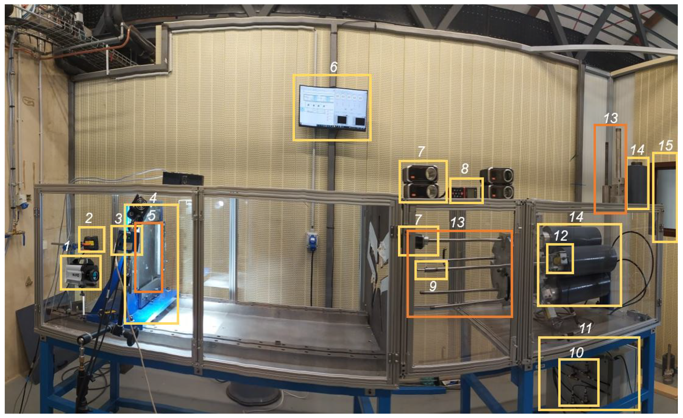
2.2. Methods
3. Results and Discussion
3.1. Effect of Distance Between Impacts
3.1.1. Mono-Impact Configurations
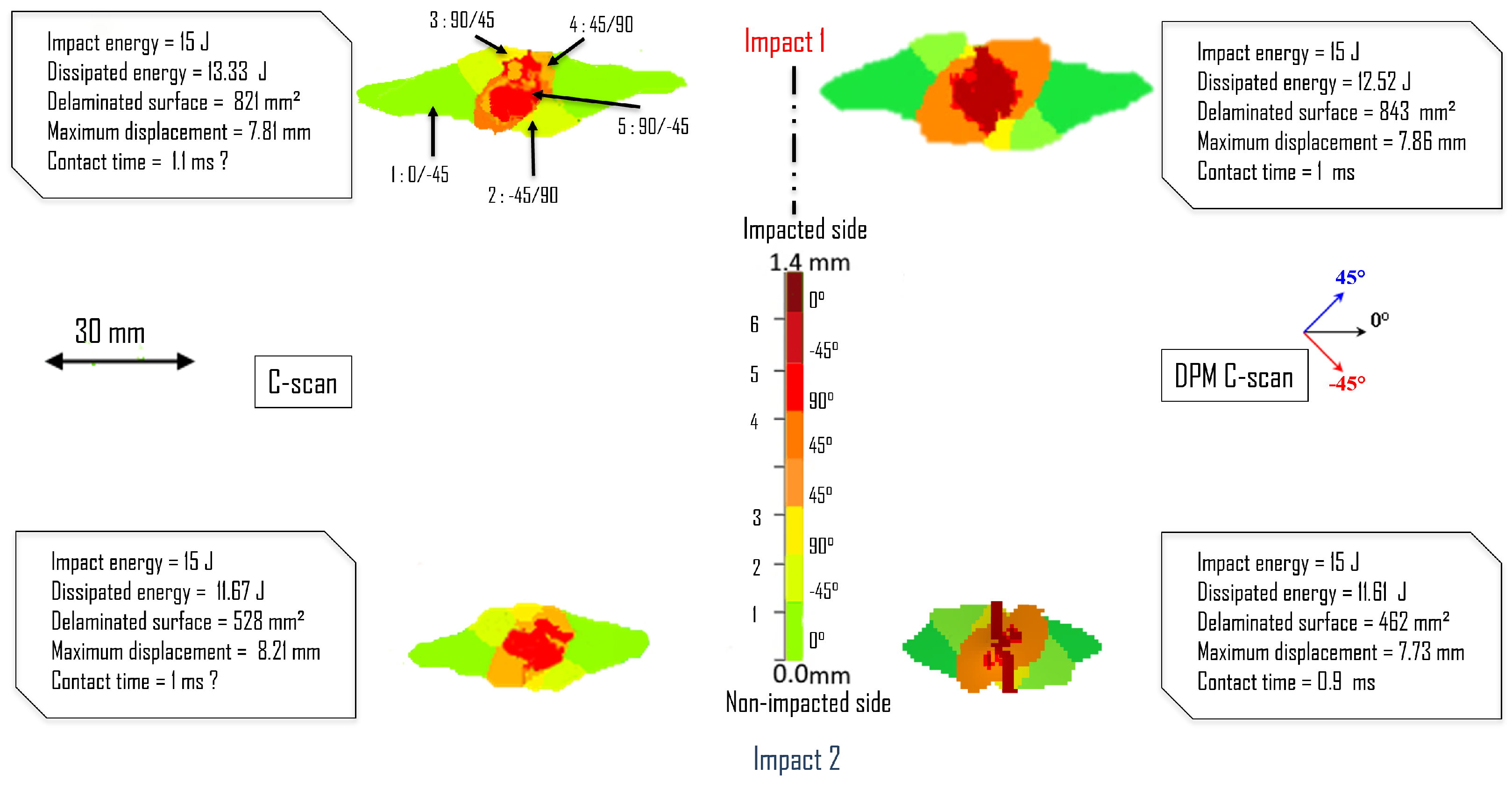
3.1.2. Configuration 15J/O/2
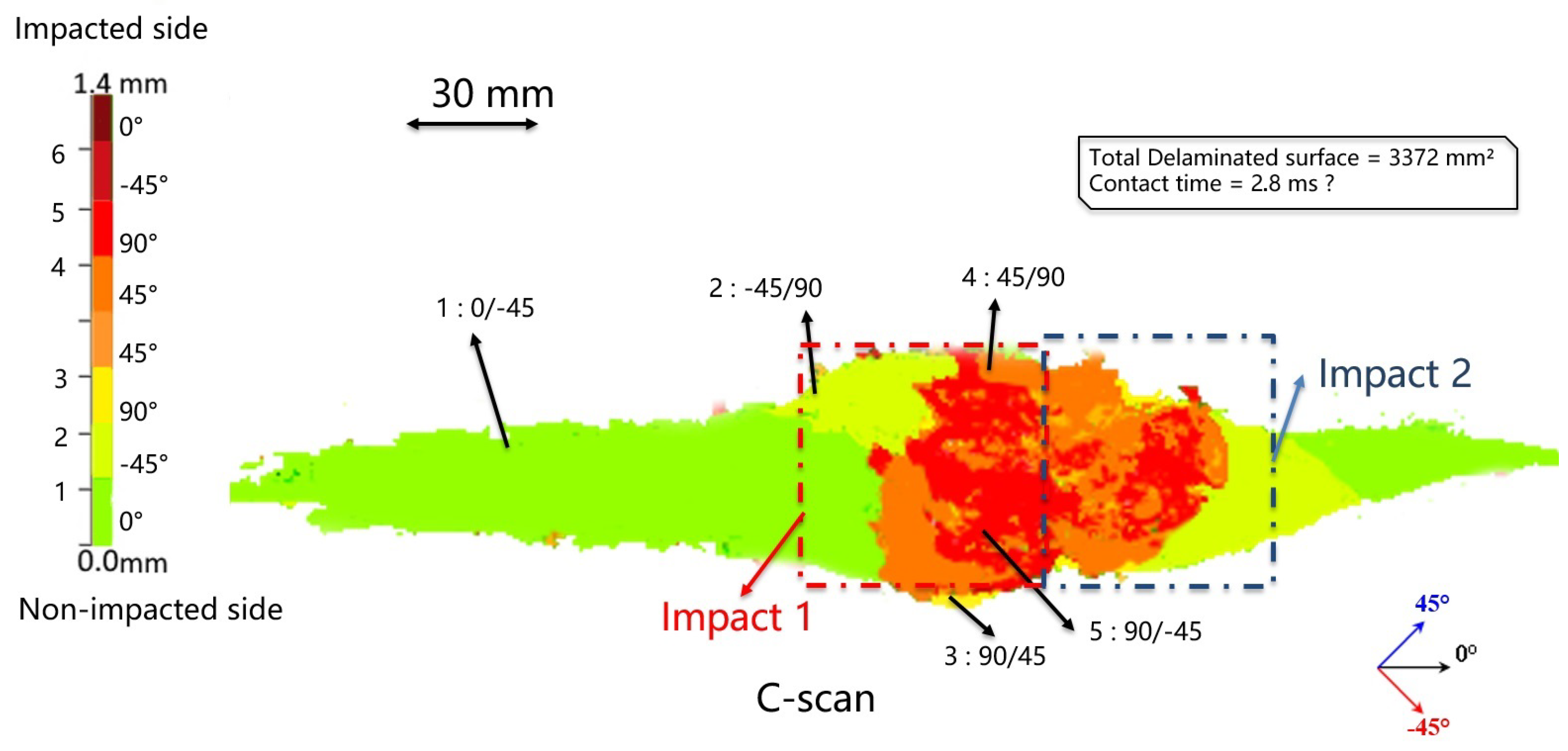
3.1.3. Configuration 15J/P/2

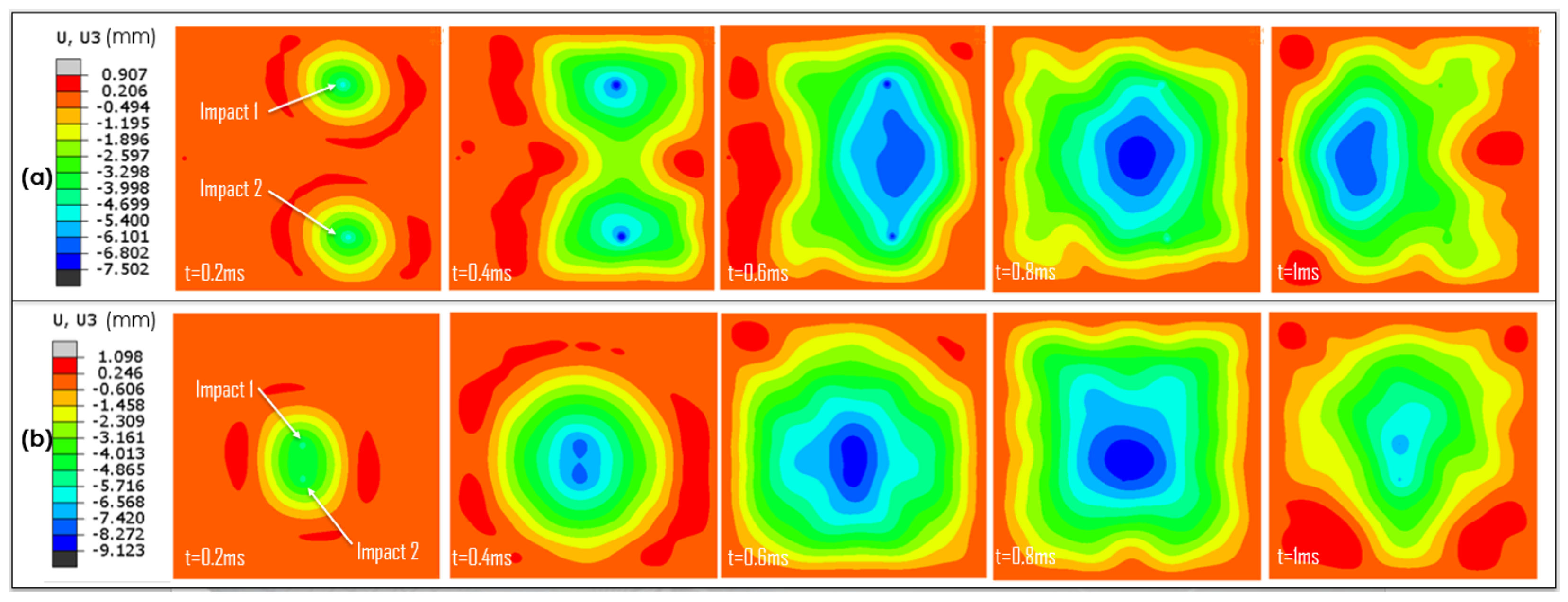

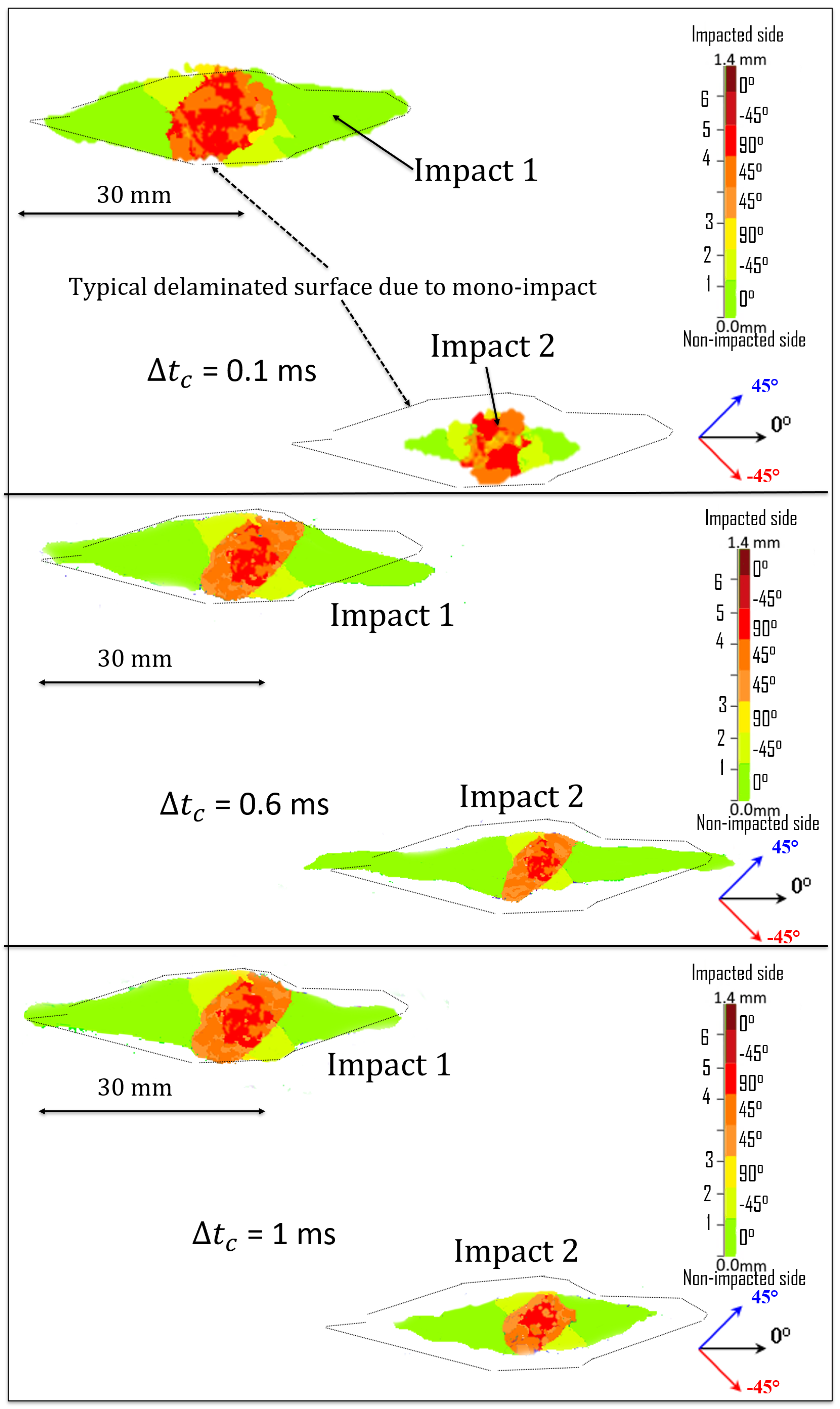
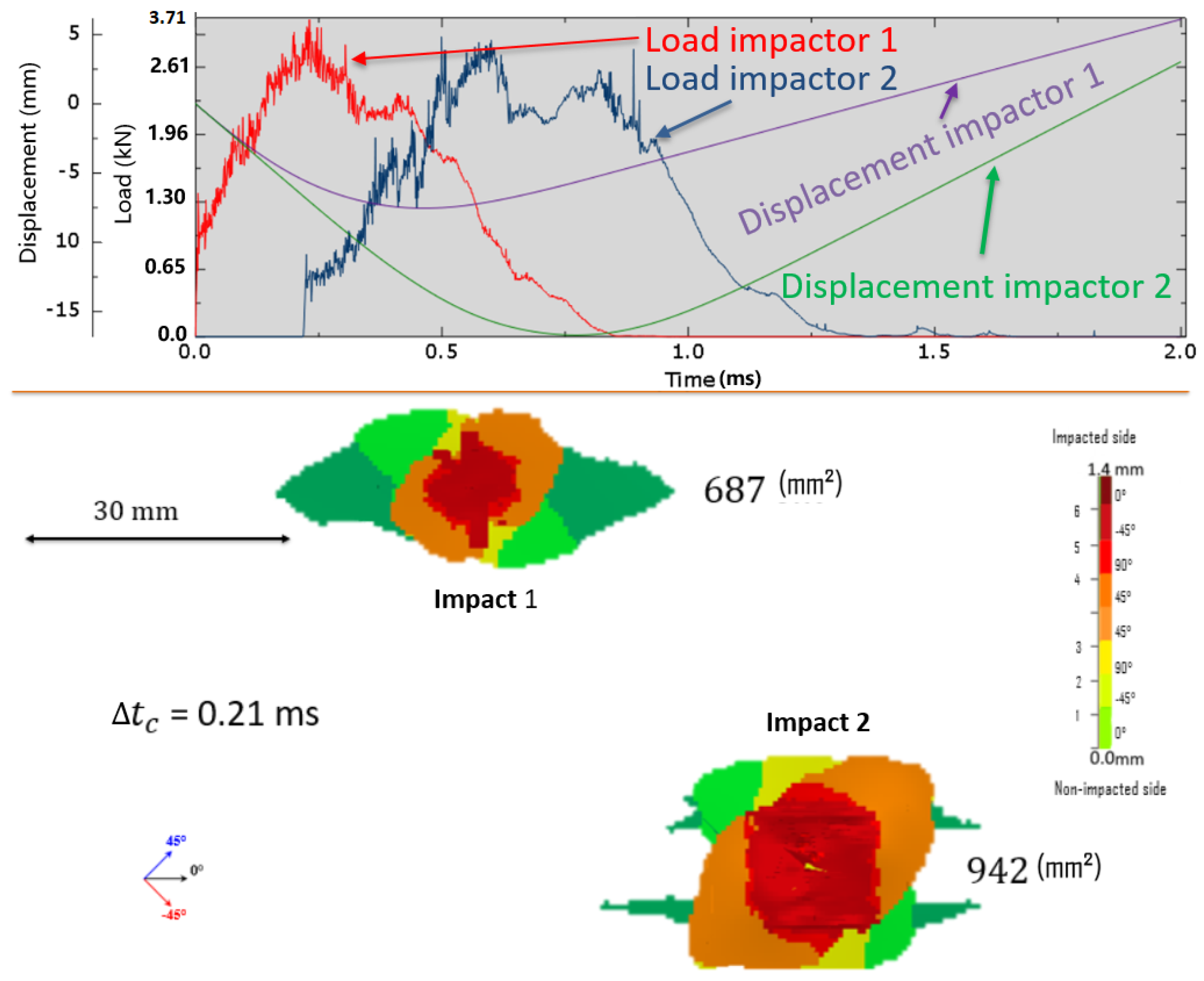
3.2. Simultaneous Impacts: Effect of Time Lag

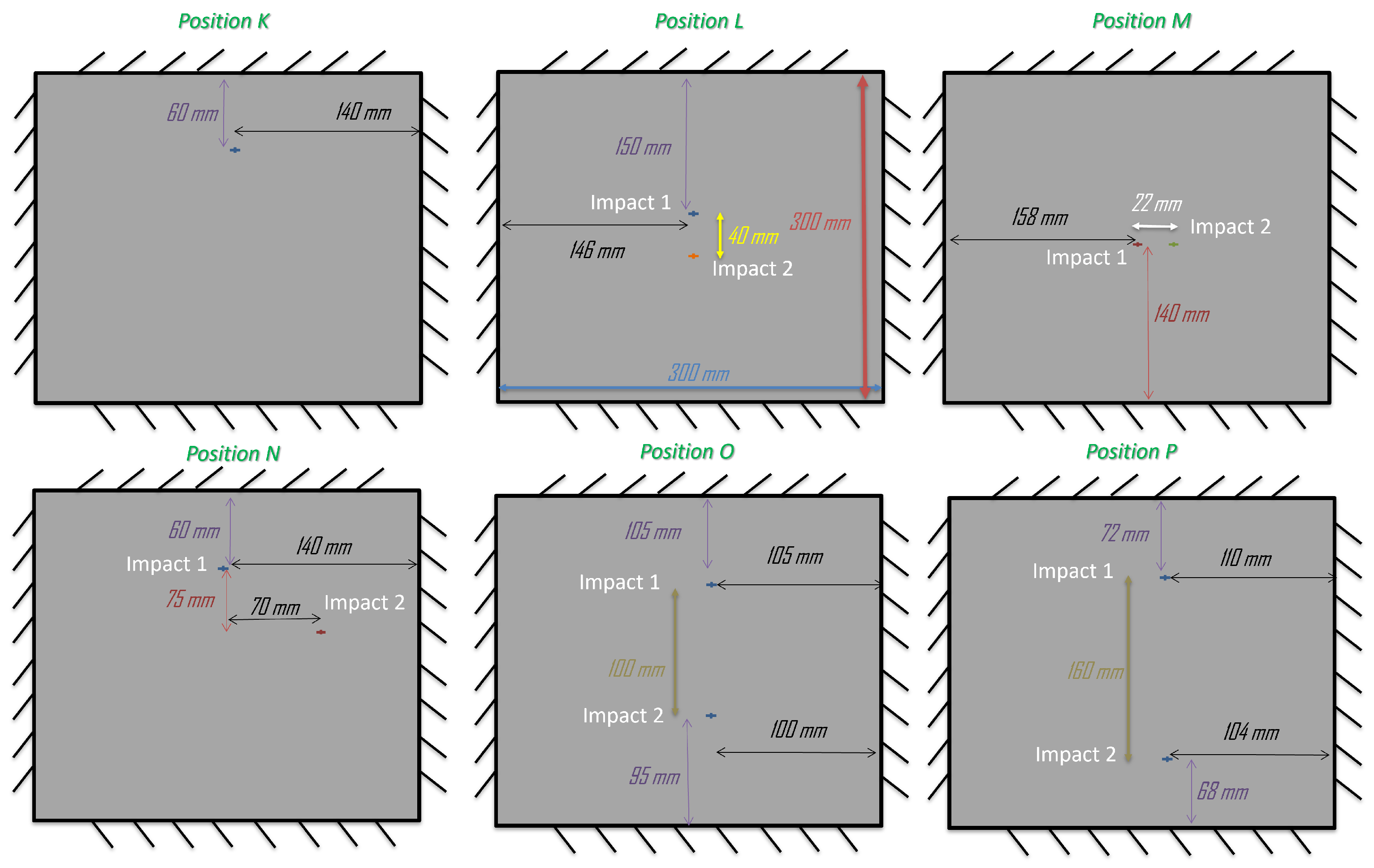
| Configuration | Figure Reference | Variables |
|---|---|---|
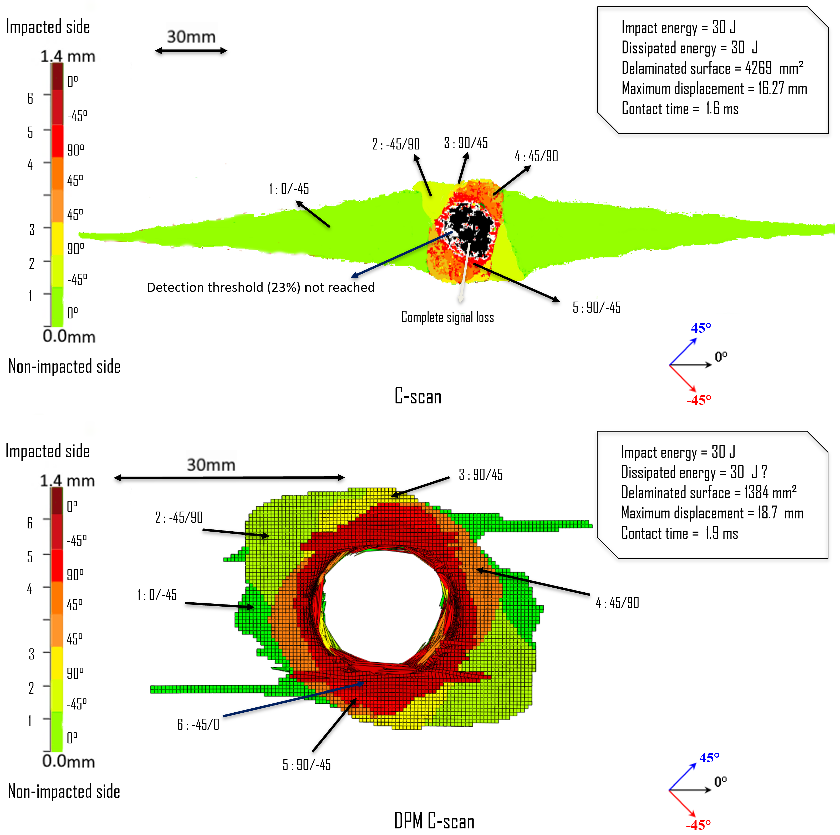
| 15J/K/1 | Figure 4 | Energy (single impact) |
| 30J/K/1 | Figure 5 | Energy (single impact) |
| 15J/L/2 | Figure 11 | Distance between 2 quasi-simultaneous impacts |
| 15J/M/2 | Figure 8 | Distance between 2 quasi-simultaneous impacts |
| 15J/N/2 | Figure 13 | Time lag between 2 quasi-simultaneous impacts |
| 15J/O/2 | Figure 7 | Distance between 2 quasi-simultaneous impacts |
| 15J/P/2 | Figure 9 | Distance between 2 quasi-simultaneous impacts |
3.3. Simultaneous Impacts: Effect of the Number of Impacts
Mono-Impact and Two Simultaneous Impacts
4. Conclusions
Author Contributions
Funding
Institutional Review Board Statement
Informed Consent Statement
Data Availability Statement
Acknowledgments
Conflicts of Interest
References
- Cesari, F.; Dal Re, V.; Minak, G.; Zucchelli, A. Damage and residual strength of laminated carbon–epoxy composite circular plates loaded at the centre. Compos. Part A Appl. Sci. Manuf. 2007, 38, 1163–1172. [Google Scholar] [CrossRef]
- Xiao-Yu, S.; Jian-Xin, T.; Zheng, H.; Xuan, G. A study on the failure mechanisms of composite laminates simultaneously impacted by two projectiles. Adv. Compos. Lett. 2018, 27, 96–106. [Google Scholar] [CrossRef]
- Abrate, S. Impact Engineering of Composite Structures; CISM International Centre for Mechanical Sciences: Udine, Italy, 2011; pp. 97–128. [Google Scholar]
- Wang, C.; Yew, C.H. Impact damage in composite laminates. Comput. Struct. 1990, 37, 967–982. [Google Scholar] [CrossRef]
- Davies, G.A.O.; Olsson, R. Impact on composite structures. Aeronaut. J. 2004, 108, 541–563. [Google Scholar] [CrossRef]
- Cantwell, W.J.; Worton, J. Comparison of the low and high velocity impact response of CFRP. Compos. J. 1989, 20, 545–551. [Google Scholar] [CrossRef]
- Mokhtar, H.B. Contribution to the Study of Impact Damage on Composite Laminates: The Effect of Hygrothermal Ageing and Preloading. Ph.D Thesis, University of Burgundy, Dijon, France, 2012; pp. 78–85. [Google Scholar]
- Amouzou, A.S.E.; Sicot, O.; Chettah, A.; Aivazzadeh, S. Experimental characterization of composite laminates under low-velocity multi-impact loading. J. Compos. Mater. 2019, 53, 2391–2405. [Google Scholar] [CrossRef]
- Amaro, A.; Reis, P.; Moura, M.; Neto, M. Influence of multi-impacts on GRP composite laminates. Compos. Part B 2013, 52, 93–99. [Google Scholar] [CrossRef]
- Bartus, S. Simultaneous and Sequential Multi-Site Impact Response of Composite Laminates. Ph.D. Thesis, University of Alabama at Birmingham, Birmingham, Alabama, 2006; p. 49. [Google Scholar]
- Sultan, M.T.H.; Basri, S.; Rafie, A.S.M.; Mustapha, F.; Majid, D.L.; Ajir, M.R. High velocity impact damage analysis for glass epoxy laminated plates. Adv. Mater. Res. 2012, 399–401, 2318–2328. [Google Scholar] [CrossRef]
- Rohrbach, Z.J.; Buresh, T.R.; Madsen, M.J. Modeling the exit velocity of a compressed air cannon. Am. J. Phys. 2012, 80, 24–26. [Google Scholar] [CrossRef]
- Woojin, S.; Jihoon, K.; Kyeong, S.J.; Thi, T.G.L.; Jeonglae, K.; Dong, H.K.; Hyoungsoon, L.; Jaiyoung, R. Parametric study of a projectile launched by a compressed air cannon. J. Mech. Sci. Technol. 2023, 37, 5913–5933. [Google Scholar] [CrossRef]
- Paredes-Gordillo, M.A.; Ivańez, I.; Garía-Castillo, S.K. Numerical study of the simultaneous multiple impact phenomenon on CFRP plates. Compos. Struct. 2023, 320, 117194. [Google Scholar] [CrossRef]
- Rezasefat, M.; Beligni, A.; Sbarufatti, C.; Amico, S.C.; Manes, A. Experimental and Numerical Study of the Influence of Pre-Existing Impact Damage on the Low-Velocity Impact Response of CFRP Panels. Materials 2023, 16, 914. [Google Scholar] [CrossRef]
- Kueh, A.B.H.; Sabah, S.H.A.; Qader, D.N.; Drahman, S.H.; Amran, M. Single and Repetitive Low-Velocity Impact Responses of Sandwich Composite Structures with Different Skin and Core Considerations: A Review. Case Stud. Constr. Mater. 2023, 18, e01908. [Google Scholar] [CrossRef]
- Huo, L.; Kassapoglou, C.; Alderliesten, R.C. Influence of Neighbouring Damage on Delamination Growth in Multiple Indented Composites. Mater. Des. 2023, 227, 111723. [Google Scholar] [CrossRef]
- Deka, L.J.; Bartus, S.D.; Vaidya, U.K. Multi-Site Impact Response of S2-Glass/Epoxy Composite Laminates. Compos. Sci. Technol. 2009, 69, 725–735. [Google Scholar] [CrossRef]
- Vaidya, U.K.; Deka, L.J. Single and Multisite Impact Response of S2-Glass/Epoxy Balsa Wood Core Sandwich Composites. In Major Accomplishments in Composite Materials and Sandwich Structures; Springer: Dordrecht, The Netherlands, 2009; pp. 541–569. [Google Scholar]
- Garzon-Hernandez, S.; Garcia-Gonzalez, D.; Arias, A. Multi-Impact Mechanical Behaviour of Short Fibre Reinforced Composites. Compos. Struct. 2018, 202, 241–252. [Google Scholar] [CrossRef]
- Jackson, M.; Shukla, A. Performance of sandwich composites subjected to sequential impact and air blast loading. Compos. Part B 2011, 42, 155–166. [Google Scholar] [CrossRef]
- Deka, L.J.; Bartus, S.D.; Vaidya, U.K. Numerical modeling of simultaneous and sequential multi-site impact response of S-2 glass/epoxy composite laminates. In Composites & Polycon; American Composites Manufacturers Association: Tampa, FL, USA, 2007. [Google Scholar]
- Hall, Z.E.C.; Liu, J.; Brooks, R.A.; Liu, H.; Dear, J.P. Impact testing on the pristine and repaired composite materials for aerostructures. Appl. Mech. 2023, 4, 421–444. [Google Scholar] [CrossRef]
- Safri, S.N.A.; Sultan, M.T.H.; Yidris, N.; Mustapha, F. Low velocity and high velocity impact test on composite materials—A review. Int. J. Eng. Sci. 2014, 3, 50–60. [Google Scholar]
- Costa, U.O.; Nascimento, L.F.C.; Garcia, J.M.; Bezerra, W.B.A.; Monteiro, S.N. Evaluation of Izod impact and bend properties of epoxy composites reinforced with mallow fibers. J. Mater. Res. Technol. 2020, 9, 373–382. [Google Scholar] [CrossRef]
- Hufenbach, W.; Ibraim, F.M.; Langkamp, A.; Böhm, R.; Hornig, A. Charpy impact tests on composite structures—An experimental and numerical investigation. Compos. Sci. Technol. 2008, 68, 2391–2400. [Google Scholar] [CrossRef]
- Sfarra, S.; Ibarra-Castanedo, C.; Santulli, C.; Paoletti, A.; Paoletti, D.; Sarasini, F.; Bendada, A.; Maldague, X. Falling weight impacted glass and basalt fibre woven composites inspected using non-destructive techniques. Compos. Part B Eng. 2013, 45, 601–608. [Google Scholar] [CrossRef]
- VanderKlok, A.; Stamm, A.; Dorer, J.; Eryi, H.; Auvenshine, M.; Pereira, J.M.; Xiao, X. An experimental investigation into the high velocity impact responses of S2-glass/SC15 epoxy composite panels with a gas gun. Int. J. Impact Eng. 2018, 111, 244–254. [Google Scholar] [CrossRef]
- Deconinck, P. Étude du Comportement à L’Impact de MatéRiaux Composites RenforcéS par Tufting. Ph.D Dissertation, University of Lorraine, Nancy, France, 2014; pp. 13–16. [Google Scholar]
- Gama, B.A.; Lopatnikov, S.L.; Gillespie, J.W., Jr. Hopkinson bar experimental technique: A critical review. Appl. Mech. Rev. 2004, 57, 223–250. [Google Scholar] [CrossRef]
- Lamberson, L. Investigations of high-performance fiberglass impact using a combustionless two-stage light-gas gun. Procedia Eng. 2015, 103, 341–348. [Google Scholar] [CrossRef]
- Zhou, H.; Jing, K.; Xie, S.; Feng, Z.; Wang, H. Experiment of high-speed cumulative impact of carbon fiber plate based on air cannon. Sci. Technol. Compos. Mater. 2023, 40, 29–35. [Google Scholar]
- Soufri, A.; Chettah, A.; Piezel, B.; Bouvet, C. A newly developed compressed air cannon test bench designed for multi-impact analysis of composite structures. Appl. Mech. 2024, 5, 997–1010. [Google Scholar] [CrossRef]
- Soufri, A. Multi-Impact Behavior of Composite Structures: Experimental and Numerical Approach. Ph.D. Thesis, University of Burgundy, Dijon, France, 2023. [Google Scholar]
- Gurit. SE 84LV: Epoxy-Based Prepreg Curing at Low Temperature (SE84LV-25-0519). 2007. Available online: https://www.gurit.com/ (accessed on 8 December 2024).
- Ravi, C.; Nistal, A.; Falzon, B.G.; Hawkins, S.C. Mode I Interlaminar Fracture Toughness of Carbon Nanotube Web-Modified Polymer Composites. In Proceedings of the 21st International Conference on Composite Materials (ICCM21), Xi’an, China, 20–25 August 2017. [Google Scholar]
- Falzon, B.G.; Hawkins, S.C.; Huynh, C.P.; Radjef, R.; Brown, C. An investigation of Mode I and Mode II fracture toughness enhancement using aligned carbon nanotubes forests at the crack interface. Compos. Struct. 2013, 106, 65–73. [Google Scholar] [CrossRef]
- Leonardo, S.D.; Nistal, A.; Catalanotti, G.; Hawkins, S.C.; Falzon, B.G. Mode I interlaminar fracture toughness of thin-ply laminates with CNT webs at the crack interface. Compos. Struct. 2019, 225, 111178. [Google Scholar] [CrossRef]
- Bouvet, C.; Castanie, B.; Bizeul, M.; Barrau, J.J. Low velocity impact modelling in laminate composite panels with discrete interface elements. Int. J. Solids Struct. 2009, 46, 3820–3836. [Google Scholar] [CrossRef]


| (Volumetric mass density) | |
| = 134,000 MPa | (Tensile Young’s modulus) |
| = 121,000 MPa | (Compressive Young’s modulus) |
| = 8300 MPa | (Transverse Young’s modulus) |
| (Poisson’s ratio) | |
| = 5200 MPa | (Shear modulus in the plane) |
| (Shear modulus through thickness) | |
| = 40 MPa | (Transverse failure stress in traction) |
| = 90 MPa | (Shear failure stress) |
| = 200 MPa | (Crushing stress) |
| = 0.0185 | (Tensile fiber failure strain) |
| (Compressive fiber failure strain) | |
| = 0.25 N/mm | (Delamination mode I fracture toughness) |
| = 1 N/mm | (Delamination mode II fracture toughness) |
| (Compression reinforcement coefficient) | |
| = 60 N/mm | (Tensile fiber fracture toughness) |
| = 10 N/mm | (Compressive fiber fracture toughness) |
| = 1,000,000 MPa/mm | (Matrix cracking interface stiffness) |
Disclaimer/Publisher’s Note: The statements, opinions and data contained in all publications are solely those of the individual author(s) and contributor(s) and not of MDPI and/or the editor(s). MDPI and/or the editor(s) disclaim responsibility for any injury to people or property resulting from any ideas, methods, instructions or products referred to in the content. |
© 2025 by the authors. Licensee MDPI, Basel, Switzerland. This article is an open access article distributed under the terms and conditions of the Creative Commons Attribution (CC BY) license (https://creativecommons.org/licenses/by/4.0/).
Share and Cite
Soufri, A.; Chettah, A.; Bouvet, C. Comparative Study of Composite Delamination Under Quasi-Simultaneous Impacts. Aerospace 2025, 12, 669. https://doi.org/10.3390/aerospace12080669
Soufri A, Chettah A, Bouvet C. Comparative Study of Composite Delamination Under Quasi-Simultaneous Impacts. Aerospace. 2025; 12(8):669. https://doi.org/10.3390/aerospace12080669
Chicago/Turabian StyleSoufri, Ayoub, Ameur Chettah, and Christophe Bouvet. 2025. "Comparative Study of Composite Delamination Under Quasi-Simultaneous Impacts" Aerospace 12, no. 8: 669. https://doi.org/10.3390/aerospace12080669
APA StyleSoufri, A., Chettah, A., & Bouvet, C. (2025). Comparative Study of Composite Delamination Under Quasi-Simultaneous Impacts. Aerospace, 12(8), 669. https://doi.org/10.3390/aerospace12080669