1. Introduction
With the increasingly frequent development of ocean resources, aircraft are increasingly utilized in maritime defense operations. Helicopters, due to their flexibility, hovering capability, low-altitude flight characteristics, and relative ease of operation, are widely employed in maritime patrol and rescue missions. However, the significant increase in helicopter maritime missions has led to a corresponding rise in the number of helicopter malfunctions. According to incomplete statistical data from the European helicopter accident database [
1], 46 helicopter water accidents occurred between 1997 and 2006, resulting in numerous casualties. Among these, 33 were attributed to structural or flotation failures that caused rapid sinking after ditching, while 5 floated initially but later capsized due to insufficient static stability. As time has progressed, helicopter water ditching accidents have significantly increased; from 2005 to 2022, the National Transportation Safety Board (NTSB) [
2] reported 237 cases of helicopter water ditching. The accident analysis emphasized that, to ensure passenger safety, helicopters must possess sufficient flotation and anti-roll capabilities to provide sufficient time for rescue operations.
Helicopter water emergency ditching behavior can be subdivided into four major consecutive phases, as follows [
3]: approach, impact, landing, and flotation, as detailed by Lindenau [
4]. During the flotation phase, a helicopter’s lateral stability refers to its ability to return to its original equilibrium position after being tilted [
5]. If the helicopter gradually tilts from its equilibrium position with a very small angular velocity, the relationship curve between the helicopter’s tilt angle and the recovery torque is defined as the static-stability recovery torque curve, commonly referred to as the static-stability curve. Research in this area primarily focuses on the calculation and analysis of factors influencing restoring torque. Numerous scholars have investigated this issue through experimental studies and numerical simulations.
Experimental investigations into helicopter flotation have been established and developed over an extended period. Scaled models, typically based on the Froude similarity principle, are commonly employed to reduce the high costs associated with full-scale testing [
6]. Early work by Kidwell and Crago [
7] in 1954 involved model experiments examining the effects of structural selection and scaling ratio on helicopter water ditching and floating performance. Based on their findings, they proposed initial requirements and an experimental process for model production applicable to helicopter water ditching and floating characteristics research. Subsequently, in 1968, they [
8] conducted a study on the floating characteristics of the Bell 206A helicopter in severe sea conditions through model experiments based on existing experimental methods. The results indicated that even under severe breaking-wave conditions, the helicopter maintained stable flotation without capsizing. Wilson [
9] presented forced ditching and floating tests conducted by Westland Airlines on a 1:10 scale model of the EH101 civil helicopter, confirming that the aircraft equipped with flotation airbags exhibited good floating performance. This experiment involved simulating 2/3 of the calibrated thrust on the helicopter, thus bringing the test conditions closer to real-world scenarios. Harry Muttery [
10] conducted forced ditching and floating tests on a 1:12 scaled model of the V-22 Osprey tilt rotor aircraft. The results showed that the V-22 exhibited good static stability, with its maximum static-stability moment occurring at a heeling angle of approximately 48°. In recent years, with the development of helicopter anti-wind and wave evaluation technology [
11], flotation tests have increasingly focused on assessing static stability in calm water. In 2008, a 1:5 scale helicopter model with flotation airbags was tested to statistically analyze the ditching overload and pressure at different velocities and postures [
12]. Subsequently, the same model was utilized, and a floating experiment was carried out to study lateral stability [
13]. Furthermore, in 2016, this team [
14] developed a model of the civil helicopter AC313 to investigate the dynamic response under different sea conditions and initial postures in calm water. The experimental process and steps were described in detail, and the results were analyzed and compared with Russian data. Based on these findings, experimental capabilities were demonstrated, and technological references were provided for further study. Finally, in 2018, the civil helicopter AC313 was employed for testing, with a model scale of 1:8, to study the helicopter’s lateral stability after ditching [
15].
The stability of a helicopter floating on water, as investigated in the aforementioned experiments, primarily involves two key aspects [
16], as follows: the static equilibrium attitude and the static-stability curve. The static equilibrium attitude [
17] evaluates whether the helicopter can maintain balance on the water surface in calm water and whether the waterline position remains below the cabin door to ensure passenger safety. The static-stability curve [
18] is primarily used to assess the sea state levels the helicopter can endure without capsizing. As the static equilibrium attitude represents a special case within the broader concept of static stability, this paper focuses on a correlational study of the static-stability curve.
Currently, two widely used methods for calculating the floating characteristics of helicopters in calm water are the drainage volume method and the fluid-structure interaction (FSI) method [
19]. The drainage volume method [
20], commonly used in ship theory, essentially determines that an object reaches a static equilibrium attitude when the mass of the displaced water equals the mass of the object, and the center of buoyancy aligns vertically with the center of gravity. Similarly, the static-stability curve is derived by examining the volume of water displaced at different lateral angles, where the resulting buoyancy force balances gravity, and deviations occur only in the vertical and lateral directions between the center of buoyancy and the center of gravity. As such, this method is limited to calculating the static floating characteristics of a single rigid body in water. Given the structural complexity of helicopters, which typically rely on multiple flotation airbags, this approach tends to overestimate static stability. The FSI method [
21] treats the problem dynamically, simulating the helicopter’s movement from an initial position to a final equilibrium state under the influence of gravity and hydrodynamic forces. However, due to the need to calculate the interaction between the water and the helicopter, as well as the deformation of the airbag under external forces, the required computational resources are substantial, often requiring several months to calculate a single state, which does not meet the time constraints of actual design.
Wang [
13] used the drainage volume method to generate the static-stability curve of the AC313 helicopter equipped with flotation airbags and compared the results with experimental data, showing good agreement. However, the drainage volume method does not account for factors such as flexible body deformation or relative displacement between multiple components. These limitations significantly reduce its applicability to the static-stability calculation of helicopters equipped with flotation airbags, and accurate results can only be expected in a few special designs.
With advancements in numerical computing software and hardware, the arbitrary Lagrangian–Eulerian (ALE) method has increasingly been applied to simulate helicopter flotation on water [
22]. The core principle of this method is to describe the flow field characteristics during the flotation process using the ALE framework, simulate the interaction between the helicopter and the water surface through penalty function-based coupling constraints, and apply the explicit dynamics method to model the static floating behavior. Ma [
23] and Wang [
24] investigated this method and conducted experimental validation. The results demonstrated that the helicopter’s motion responses were in good agreement with experimental data. However, the numerical simulations were computationally intensive, with a single static state often requiring more than 50 h to compute.
In order to reduce the consumption of computing resources, many scholars have conducted extensive research. Luo [
25] proposed the element point method, which divides the floating body into numerous small elements represented by physical quantities. This method calculates the static moment on a certain axis through the points to assess stability, without considering the flexibility of the airbag, and it has achieved great results. In the closely related field of airships, Liu [
26] performed stress analysis and simulations of airship airbags by applying gradient pressure, with the simulation results showing good agreement with experimental data.
In summary, the study of lateral static stability of helicopters equipped with flexible flotation airbags currently faces several challenges: (1) limited research addressing lateral static stability while accounting for airbag flexibility; (2) a lack of efficient and accurate calculation methods for assessing the lateral static stability of helicopter flotation; (3) inadequate analysis of the mechanisms by which neglecting airbag flexibility affects lateral static stability.
Therefore, this paper proposes an equivalent pressure method to enable efficient and high-precision calculation of the static stability of helicopters floating on water. By comparing the results with those obtained from the ALE method and the drainage volume method, it was found that the primary sources of error in lateral static-stability calculations are airbag flexibility and relative displacement. To address these findings, this study further investigates the changes in airbag displacement at different roll angles and the variations in the helicopter’s lateral static-stability curve under different internal airbag pressures. The remainder of this paper is organized as follows.
Section 2 introduces the fundamental principles of the three computational methods used in this study, along with a theoretical error analysis concerning the definition of hydrostatic pressure.
Section 3 presents the modeling of the helicopter, airbag, and connecting straps, and outlines the calculation settings and procedures for both the drainage volume method and the gradient pressure method. In
Section 4, this paper validates the present numerical model, including both rigid and flexible results. In
Section 5, this paper presents and discusses the numerical results. In
Section 6, this paper presents the conclusions.
2. Numerical Model
The section first introduces fundamental principles of the fluid-structure coupling method, the drainage volume method, and the gradient pressure method employed in this paper. It then elaborates on the control volume approach used to simulate the inflation behavior of flexible airbags in helicopters. Finally, the primary error sources and estimation of the gradient pressure method are presented.
2.1. Fluid–Solid Coupling Method
The arbitrary Lagrangian–Eulerian (ALE) algorithm combines the advantages of the Lagrangian method and the Eulerian method to effectively track the motion of the boundary of the material structure, and can also make the internal grid elements independent of the physical entity. The governing equations in the
X-direction can be written as follows [
27]:
where
denotes the material density,
t denotes time,
v denotes the velocity of matter,
u denotes the velocity of mesh,
X denotes the material point,
denotes the Euler coordinates of
X in the
i direction,
denotes the Cauchy stress tensor,
b denotes the specific body force, and
E denotes the specific total energy.
The boundary conditions employed in the numerical model are partially the material surfaces (out-of-plane, in-plane, and bending restraints). The material surfaces defined in the ALE formulation are as follows: (a) no particles can cross them, and (b) stresses must be continuous across the surfaces. The elements of the water domain were given the null hydrodynamic material type, which allowed a new equation of state to be specified. The Grüneisen equation of state with a cubic shock velocity–particle velocity relationship is applied in our numerical model, and it defines pressure as follows [
27]:
where
E is the internal energy per initial volume,
C is the intercept of the
curve.
,
, and
are the coefficients of the slope of the
curve,
is the Grüneisen gamma, and
is the first-order volume correction to
. The edges of the water block were defined as non-reflecting boundaries, allowing the water block to be relatively small in size.
The governing equations are numerically solved by LS-DYNA. The termination time of the explicit process and the initial time step increment are defined by the user based on the processing time. This time step size is then automatically adjusted throughout the transient analysis based on the deformation and stress state of each structural element [
28]. In order to track the solid–liquid interface between the flow field and structure in the ALE method and calculate the contact force, this paper adopts the penalty function calculation method in LS-DYNA. By applying penalty forces to the fluid and solid surfaces in contact, the coupling between ALE and FEM is achieved.
2.2. Drainage Volume Method
The drainage volume method is a recognized static-stability analysis method in the field of naval architecture. It determines stability by solving equilibrium equations based on the displaced water volume.
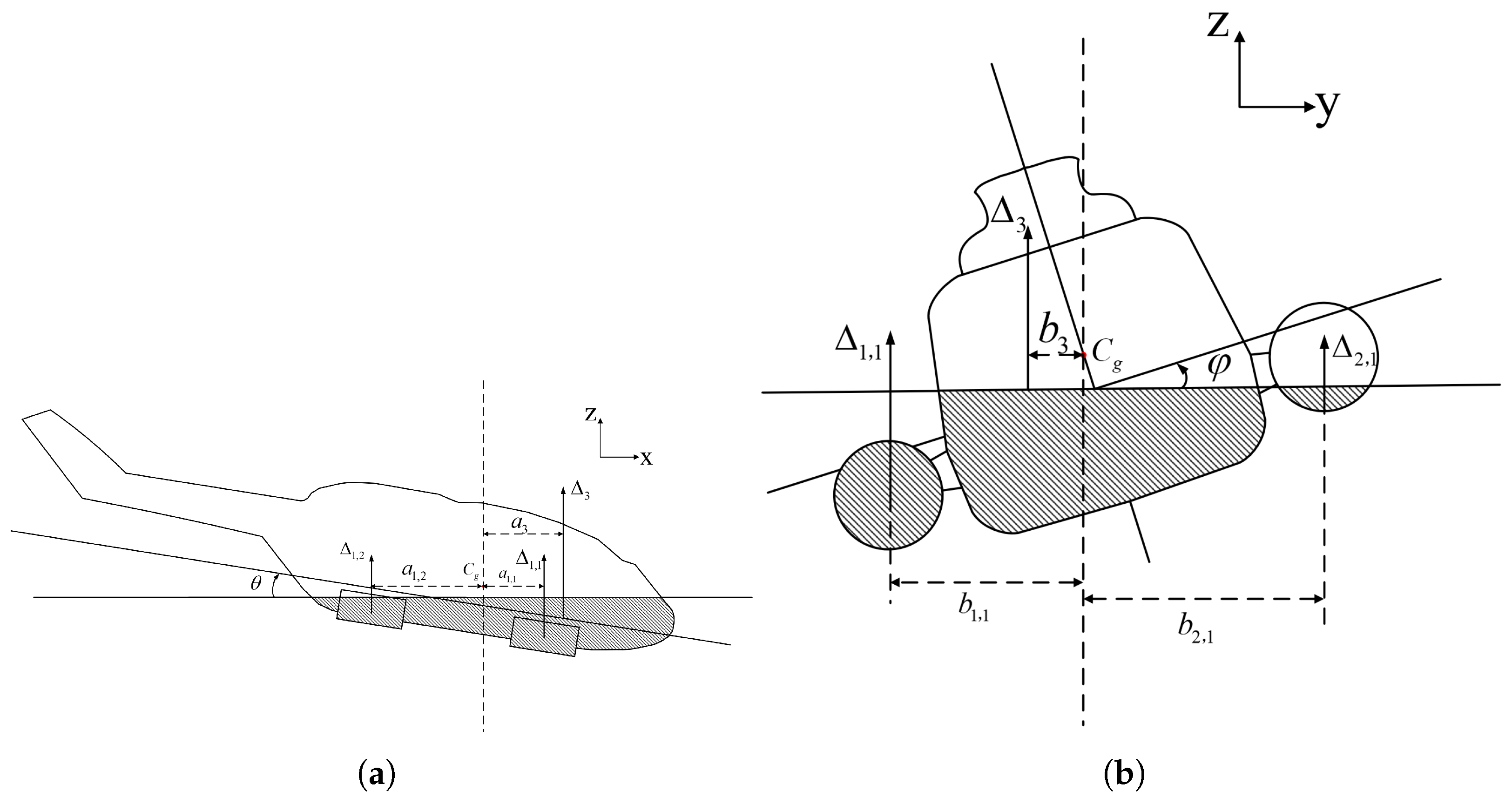
This method assumes that the helicopter, airbags, and connecting straps are all rigid bodies, and the analysis is primarily based on their geometric shape, overall center of mass, and gravitational force. In this paper, for a helicopter equipped with four airbags, where the flexibility and displacement of the airbags are neglected, the equation can be expressed as follows:
where
denotes the drainage volume of the helicopter or each airbag,
a and
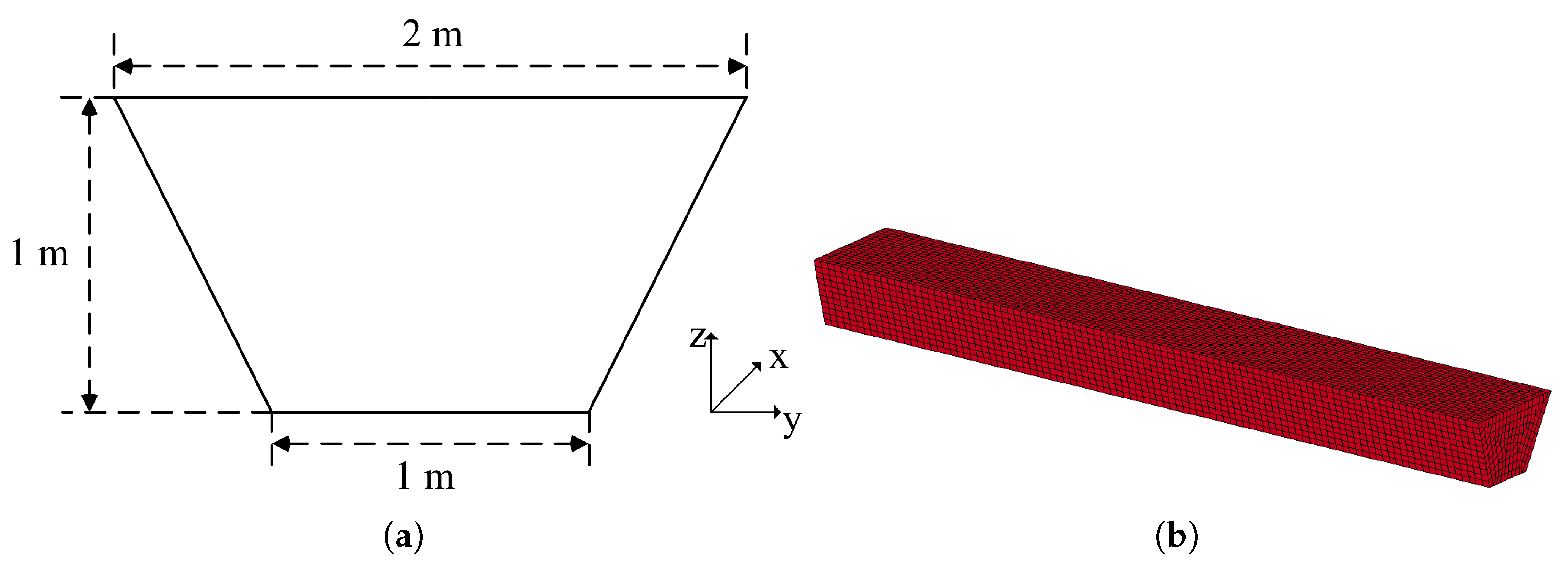
b represent, respectively, the displacement between the centroid of each drainage volume and the mass center of the helicopter. As shown in
Figure 1,
is the mass center of the helicopter,
is the trim angle that satisfies Equation (
6),
is the heel angle, the subscripts mean different parts, where ‘3’ refers to the helicopter, ‘
’ refers to the right airbag in
Figure 1a and the left in
Figure 1b, and so on; ‘
’ to ‘
’ are the other airbags.
To evaluate the lateral static stability of a helicopter equipped with airbags, the system must satisfy the buoyancy balance equation, i.e., Equation (
5), and the longitudinal balance equation, i.e., Equation (
6), at a certain lateral inclination angle,
. Thus, the problem of determining lateral static stability reduces to solving for the drainage volume.
2.3. Gradient Pressure Method
This method assumes that each element is subjected to a uniform water pressure. The helicopter is modeled as a rigid body and its mass is distributed at the centroid position, whereas the airbags and connecting straps are modeled as flexible bodies. Both the airbags and connecting straps are considered isotropic and composed of linear elastic material, and the airbags are subjected to uniform internal pressure from the inflation gas. The contact between airbags, connecting straps, and the helicopter adopts a penalty function algorithm, which assumes that the direct contact between different components is modeled as a spring connection between contact nodes, and simulates the contact force through contact stiffness and penetration. Based on these assumptions, the fundamental theory of this method is described as follows:
Due to the limitations of the drainage volume method, particularly its assumption of rigid airbags and the absence of airbag displacement, this article integrates the finite element method (FEM), formulating the equilibrium equation by representing the drainage volume as a gradient pressure.
When employing dynamic methods to evaluate the static floating characteristics of helicopters in water, the primary goal is to determine the final equilibrium state, characterized by force balance and a stationary configuration. Therefore, a detailed analysis of the motion process from the initial state to the final stationary state is unnecessary. In particular, it is not essential to consider the impact of the helicopter on the water throughout the entire process. Consequently, the surrounding water can be represented as a height-dependent pressure field applied to the helicopter’s surface.
The node number definition and normal direction on these elements are depicted in
Figure 2. Let the helicopter and airbag unit node numbers be defined as
to
; the normal direction of the element,
, is perpendicular to the surface of the element, and the direction satisfies the right-hand helix rule from
to
. The surface pressure of this element can be written as follows:
where
is the average value of the vertical coordinates of
to
. Thus, the motion of the element can be written as follows:
where
m is the total mass of the helicopter and airbag,
is the area of element
i,
,
, and
are three-dimensional unit vectors of the global coordinate system,
,
, and
are the rotational inertias of the helicopter in three directions, and
is the constraint torque.
and
are the combined force and vector of the pressure on the element. Assuming that the center of gravity of the helicopter is
,
and
can be described as follows:
To determine the heeling moment of the helicopter at a certain heeling angle, the helicopter is rotated and constrained at that angle, then by setting the left term of the equation of motion to 0, the heeling moment is obtained as the constraint torque at the given angle.
Analysis of the equation of motion presented in the previous section reveals the absence of a damping term. At this point, there is no damping term in the dynamic equation, and it is known that the initial state of the helicopter may not exactly be its final equilibrium state. If each initial value is not 0, the final calculation result will inevitably not converge, and the displacement in all three directions will exhibit periodic motion, making it difficult to obtain the final calculation result. Therefore, it is necessary to introduce damping forces in three directions to quickly converge the results without altering the final equilibrium calculation. Accordingly, this article adds an additional pressure related to velocity to each static pressure term on the element. The magnitude of this pressure is linearly related to the velocity, and the direction is opposite to that of the velocity. Therefore, the pressure on each unit is assumed to be as follows:
where
is the specified pressure-damping term,
is the velocity vector of the element, and
c is the additional damping coefficient.
The value of
c determines the time required for the system to reach its final equilibrium state, and an appropriate value can significantly reduce the computational complexity of the entire mathematical model. In this paper,
c is defined by estimating the critical damping coefficient of the entire system. The effects of different damping values on the calculation time of the system will be discussed in the following section. The critical damping coefficient can be expressed as follows:
2.4. Internal Pressure of Airbags
During the floating stability balance process of a helicopter, the external pressure applied to the airbag varies with the helicopter’s position, resulting in a change in the internal air pressure. To accurately characterize the change in airbag volume, this article uses the equivalent pressure method to standardize the external pressure of the airbag and, on the basis of knowing all node positions of the current airbag, uses the control volume method to calculate the internal pressure of the airbag, thus establishing the helicopter’s finite element equation system. The model then finds the position, deformation, and internal and external pressures at the subsequent time step.
For a single inflatable airbag, the volume can be written as follows [
29]:
Due to the sealed nature of the airbag within the floating system, its internal gas mass does not change, meaning that the internal pressure of the airbag is only related to its own volume. Therefore, through the ideal gas state equation and Green’s formula, the internal pressure of the airbag can be written as follows:
where
is the internal pressure of the airbag,
is the mass of the internal gas, which is determined by the initial internal pressure of the airbag;
T is the temperature of the internal gas—in this article, without considering thermal transformation, the gas temperature is constant;
is the average x-coordinate of all nodes on element
i.
The deformation of the airbag itself is influenced by three external forces, which have been previously specified. The airbag is modeled using shell elements and an isotropic linear elastic model [
30], so the final position changes of each node of the airbag relative to the center of gravity of the helicopter can be obtained based on the deformation coordination equation.
2.5. Error Analysis of Gradient Pressure Method
The static pressure on the element in this article is based on the assumption of uniform pressure, which is slightly inconsistent with the actual situation and may cause certain calculation errors.
Under the actual gradient pressure, the magnitude of the combined pressure on element i and the center of action in the vertical direction are as follows:
Under uniformly distributed pressure and gradient pressure, the coordinates and centroid positions of the center of action in the other two directions are the same, and the direction of the combined force of pressure is opposite to the direction of , so it is not necessary to compare.
When taking the uniformly distributed pressure, the combined force of pressure on element i and the center of action in the vertical direction are as follows:
Calculate the error caused by pressure on each element:
The value of
is as follows:
In grid partitioning, the element size is usually very small, meaning that the vertical coordinate difference between adjacent nodes is small. Therefore, if the element partitioning is reasonable, nodes with vertical coordinate positions that are nearly 0 are excluded, , and as the grid density increases and decreases, the results become more accurate.
At the same time, the formula for observing the center of pressure action is similar to the resultant force formula, so the error calculation steps are the same as above, and will not be elaborated on in this article.
3. Computational Setup for Helicopter Lateral Floating Stability
This section first presents the models and detailed parameters of the helicopter, airbags, and connecting straps utilized in this study. Next, the calculation process and implementation of the drainage volume method are briefly described. Finally, the mesh division, material properties, and calculation settings for the helicopter, airbags, and connecting straps under the gradient pressure method are introduced.
3.1. The Configuration of Parameters of the Helicopter
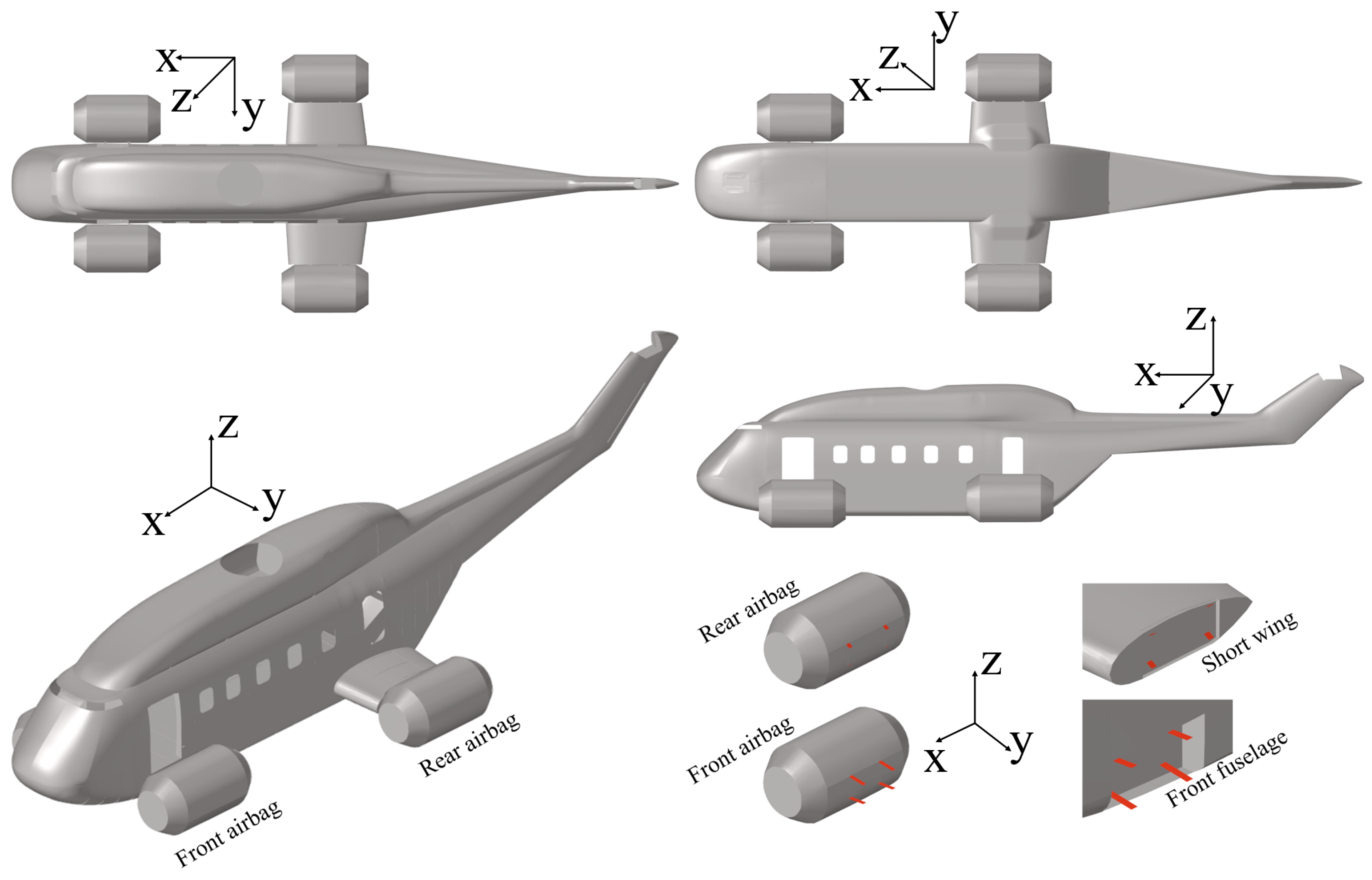
Figure 3 shows the model of the helicopter. The configuration of the helicopter system used in this study is the same as that in Wang et al. [
13] and Chen et al. [
15]. As shown in
Figure 3, the helicopter system includes the helicopter itself, four airbags, and sixteen connecting straps, and the rotor wing is ignored during the floating process.
Since the helicopter rotor does not contact the water during the floating process, and the helicopter is in an unpowered state, the rotor assembly is omitted to reduce redundant calculations. For the helicopter model, it is considered a rigid body throughout the entire calculation process. According to the lateral stability calculation, three degrees of freedom of the helicopter model are constrained during the floating process, including the translation of the y-direction (slide shift), the rotation of the z-direction (yaw), and the rotation of the x-direction (heel or roll). The 1:5 scale model is 3.74 m in the x-direction, 0.92 m in the spanwise direction, 0.56 m in the z-direction, and 103.73 kg in weight. With the head position as the coordinate origin, the center of gravity is (1.3209 m, 0.0021 m, 0.2123 m), and the corresponding moment of inertia at the center of gravity can be written as follows: , , , , , . For the airbags, each airbag is identically 0.494 m in the x-direction, 0.25 m in the y- and z-directions, and 0.0022 m in thickness. The connection straps at the front fuselage are 0.096 m in length, 0.075 m in width, and 0.002 m in thickness.
3.2. Computational Setup for the Drainage Volume Method
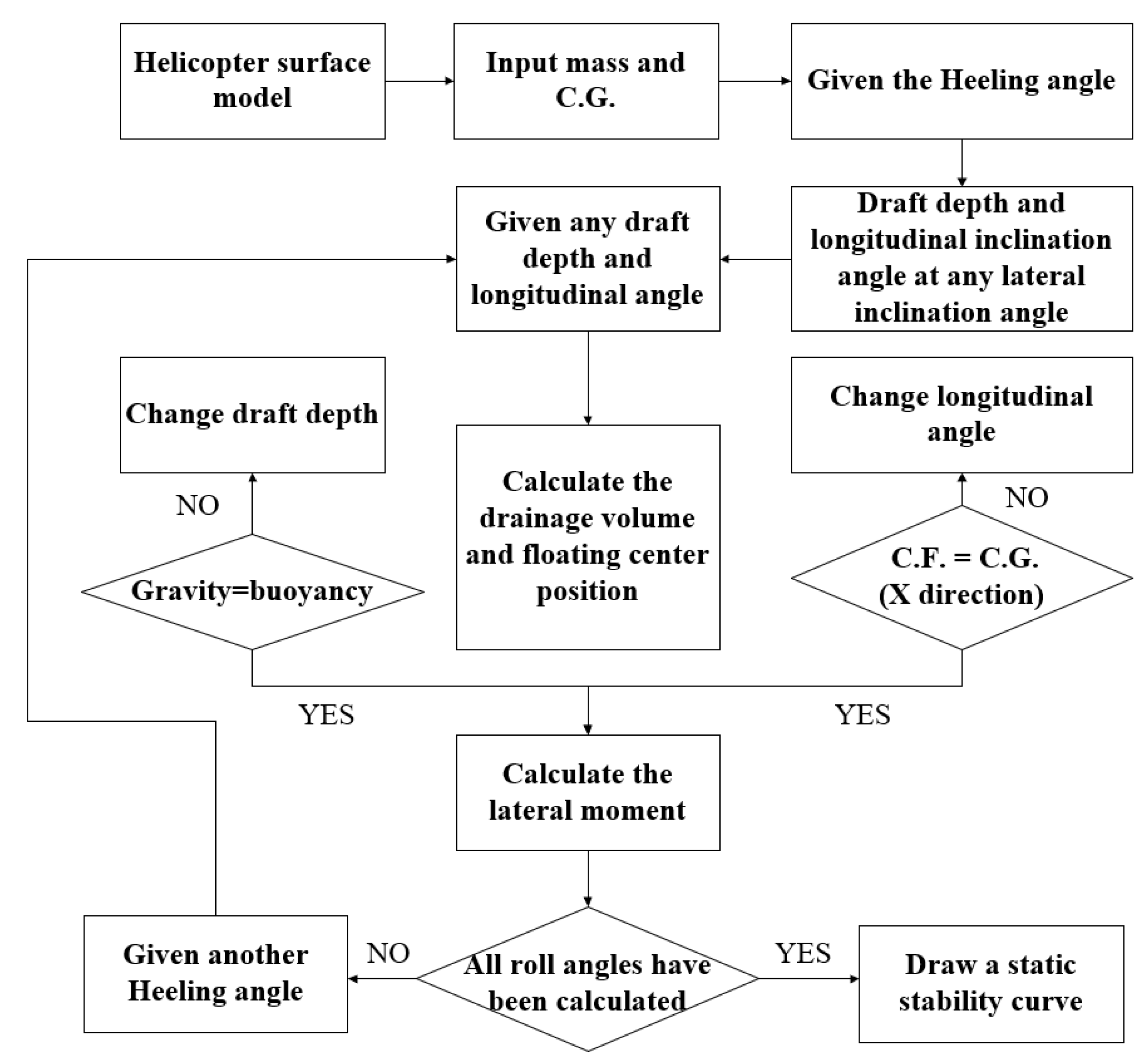
Solving for lateral static stability requires the helicopter’s buoyancy and gravity to be equal at a given lateral angle, and the longitudinal moment to be zero [
31]. Therefore, as shown in
Figure 4, the calculation process using the drainage volume method is as follows: First, the helicopter surface model is rotated to a specified lateral angle. Next, the waterline height and current longitudinal angle are defined. Then, the helicopter model is intersected with the waterline surface, constructing a closed surface representing the submerged portion. Finally, the submerged volume and centroid position are determined through surface area analysis. In this study, the helicopter model is imported into CATIA software and controlled using Visual Basic (VB). CATIA’s volume and centroid calculation module is then utilized to determine the immersed volume and centroid position. Therefore, throughout the solution process, the helicopter reaches equilibrium at the lateral angle [
32].
3.3. Computational Setup for the Gradient Pressure Method
This paper assigns the pressure to each element of the helicopter and airbags in LS-DYNA through MATLAB-24.1.0.2537033. The former defines the pressure, while the latter realizes the deformation of the entire structure and the calculation of helicopter motion.
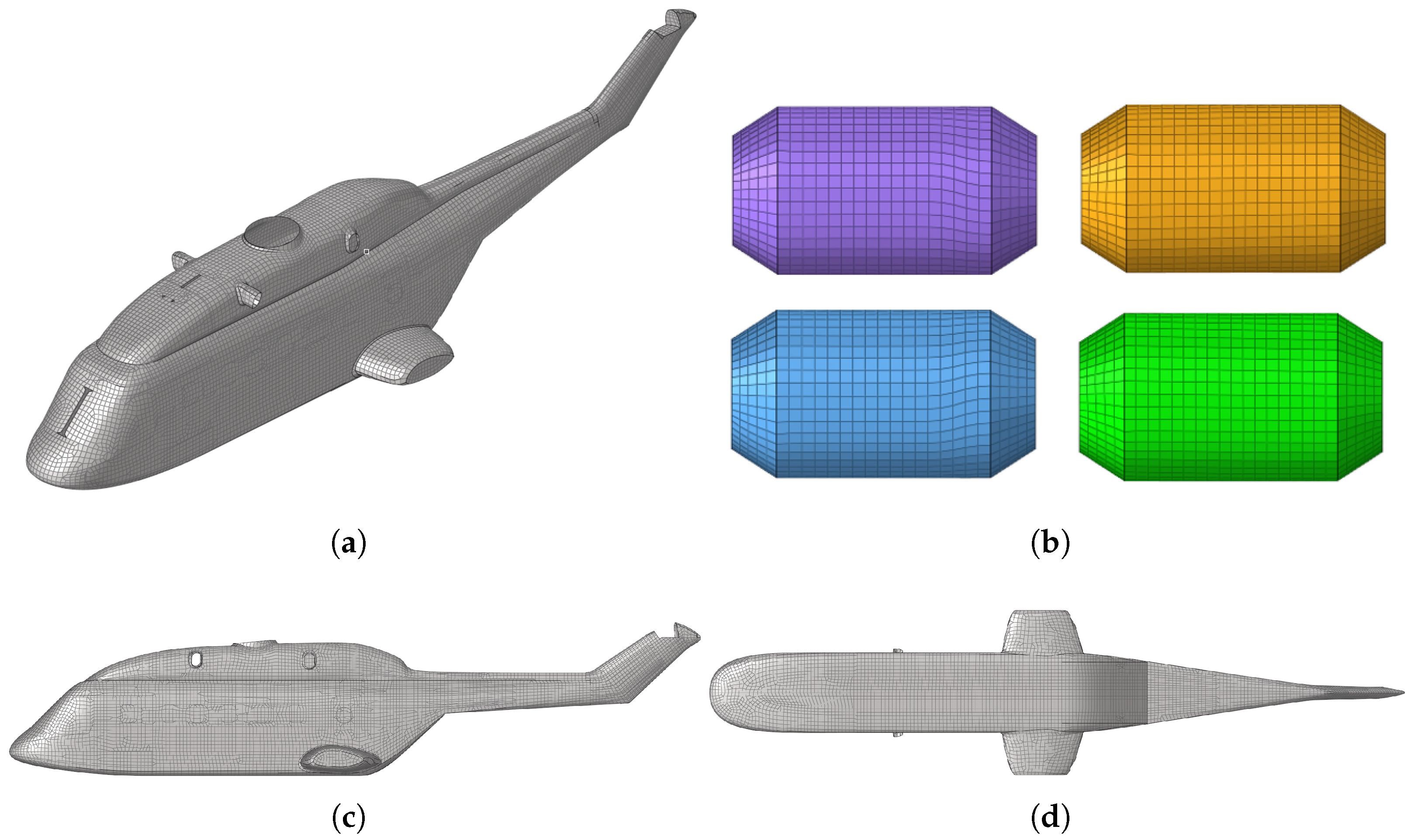
Figure 5 shows the mesh of the helicopter, airbags, and connecting straps.
As illustrated in the figure above, the helicopter airbags, connecting straps, and body are defined as different components, with each component defining a common node connection and mutual contact to achieve force transfer between different components.
Figure 3 shows a schematic diagram of the connection between the front and rear nacelles of the helicopter and the connecting straps. Each nacelle is connected to the airbags through four connection straps of the same size, and each connection strap is connected to the nacelle through a common node method.
To align with engineering practice, the helicopter is assumed to undergo negligible deformation during the floating process. Therefore, a rigid body model is used, assuming aluminum material properties, and * PART is used in the LS-DYNA INERTIA keyword, defined by assigning mass, moment of inertia, and initial velocity. The airbag and helicopter are treated as flexible units, with Kevlar 29 materials used for the airbag and polyester materials used for the connecting belt. Both materials are assumed to behave as isotropic and linear elastic solids, neglecting failure and plastic deformation effects.
Since the helicopter, airbags, and connecting straps are defined as different components, and each component is defined as a single part, it is necessary to define relevant contacts between different parts to prevent penetration. Due to the fact that the airbags, helicopters, and connecting belts in this study are all described through shell elements, there may be differences in the thickness of the elements between the parts in contact. Therefore, surface-to-surface contact is implemented using a penalty function method. Based on qualitative analysis, it can be concluded that contact only occurs between the helicopter and the four airbags, between the four connecting belts and each airbag and the helicopter, and between each nacelle and its four connecting straps.
In this article, the calculation requires adding a pressure of a certain magnitude to each element, with the pressure direction perpendicular to the surface of the element and pointing towards the inside of the helicopter, which is done by the ‘*DEFINE CURVE FUNCTION TITLE’ and ‘*LOAD SHELL ELEMENT ID’ commands of LS-DYNA. The node information is programmed and implemented using MATLAB. The specific process is as follows: (1) Check all elements’ normal vectors of the model so that they all point outward and export the k file required to generate Ls-DYNA. (2) Search for the element domain and node domain in the k file, generate a node matrix containing elements and corresponding nodes that meet the right-hand rule to make the normal direction of the element point outward. The first column of the matrix is the element number, and the second to fifth columns are the node numbers. (3) Define the function through Equation (
11), where
is given by cross-multiplication of node vectors, and each function number corresponds to the element number. (4) Write the function and corresponding unit number in a certain format in the k file through the MATLAB write command.
5. Results and Discussion
This section first studied the artificial damping parameters of a pure rigid body under the equivalent pressure method and compared the calculated results of the helicopter with those of the displacement volume method. The results were close, providing a basis for the rapid calculation of the static stability of helicopters considering flexible airbags using the equivalent pressure method. Next, numerical simulation and analysis were conducted on the helicopter model with flexible airbags. The calculated results were compared with the fluid structure coupling method and experimental results, and the results were similar. However, compared with the drainage volume method, there were significant differences. Therefore, the mechanism of how the flexibility of the airbags and connecting straps affects the lateral static stability of the helicopter was analyzed from the waterline cloud map and the airbag displacement cloud map, respectively. In response to the above findings, the influence of different initial internal pressures of airbags on the lateral static stability of the helicopter was finally studied.
5.1. Lateral Static-Stability Results for the Rigid Model
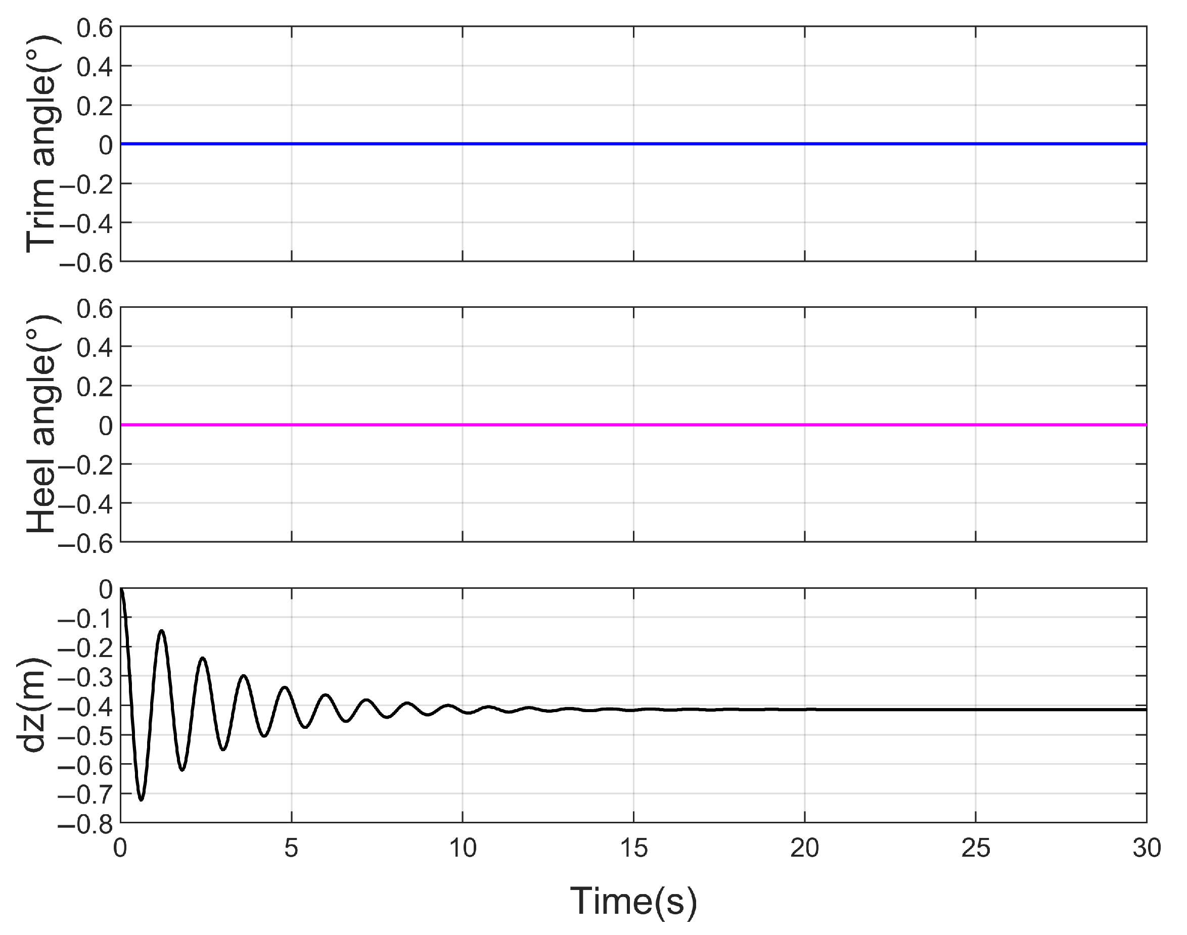
For a helicopter model that neglects the flexibility of airbags and connecting straps, the static stability is calculated using the gradient pressure method. The results are then compared with those obtained using the drainage volume method, and the influence of the damping coefficient is analyzed in terms of its effect on the accuracy and computational efficiency of the gradient pressure method. Subsequently, each airbag and connecting strap is modeled as a rigid body in LS-DYNA, with masses of 1.521 kg and 0.003 kg, respectively. Taking a 30-degree lateral inclination as an example,
Figure 11 presents the variations in the helicopter’s center of gravity height and heeling moment under different damping conditions.
As shown in
Figure 11, the vertical displacement and heeling moment curves of the helicopter vary significantly under different damping coefficients; however, the final steady-state remains consistent and aligns with theoretical expectations. When the damping coefficient is 0, the helicopter exhibits sustained periodic motion and never reaches a stationary state. With a damping coefficient of 6000, the helicopter system exhibits underdamped motion and reaches a stationary state after approximately four oscillations around the final equilibrium position. A damping coefficient of 22,574 corresponds to critical damping, while a value of 100,000 results in an overdamped system that takes about 25 s to stabilize. Therefore, this study employs the critical damping value for the overall system to define the damping for each element, ensuring both computational efficiency and accuracy.
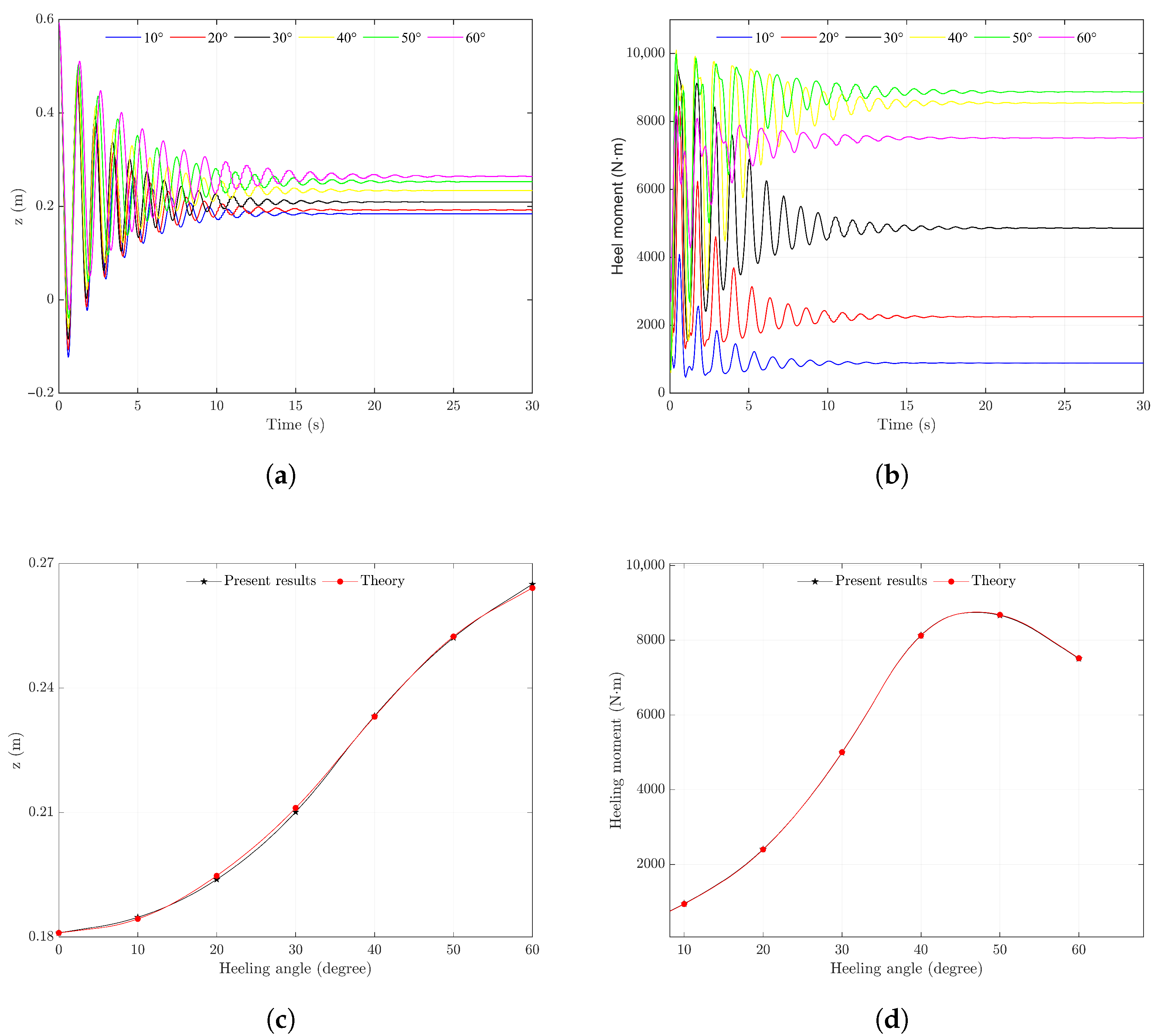
Based on the preceding research, the optimal artificial damping value for efficient computation was established. The study then proceeded to analyze the static-stability curves of a purely rigid helicopter at various roll angles. The results, presented in
Figure 12, show that the calculations obtained using the drainage volume method and gradient pressure method are in close agreement.
Analysis of the curve reveals that within a heeling angle range of to , the relationship between the heeling angle and heeling moment is approximately linear, indicating a proportional correlation. This behavior aligns with the heeling moment expression for small angles in classical ship theory. The reason is that when the helicopter undergoes a slight tilt in a free-floating state, the deformation and displacement of the airbags and connecting straps can be neglected. Under these conditions, the vertical displacement of the helicopter’s center of mass relative to the waterline is minimal, and the center of buoyancy, center of mass, and metacentric point approximately form a right triangle. Consequently, the lateral distance between the buoyancy center and the center of mass can be approximated as
In the heeling angle range of to , the static-stability moment of the helicopter gradually increases with the heeling angle. This is attributed to the geometric configuration of the helicopter, which is wider at the bottom and narrower at the top. As the heeling angle increases, the centroid of the displaced volume (i.e., the center of buoyancy) shifts further to one side relative to the helicopter’s center of mass. Since the buoyant force remains constant across different heeling angles, the increasing lateral separation between the buoyancy center and the center of mass leads to a corresponding increase in the restoring heeling moment.
When the heeling angle exceeds , the static-stability moment of the helicopter gradually decreases with increasing heeling angle. At this stage, the center of mass of the helicopter moves closer to the water surface, and the waterline rises accordingly. As a result, the centroid of the displaced volume gradually approaches the geometric center of the helicopter and moves closer to the center of mass. Consequently, the lateral arm between the buoyant force and the gravitational force decreases, leading to a reduction in the static-stability moment.
As the roll angle reaches a certain critical value, the static-stability moment of the helicopter becomes zero. This occurs because of the helicopter’s geometric configuration—narrow at both the bottom and the top. As the heeling angle approaches , the centroid of the displaced volume inevitably shifts to the opposite side of the center of mass. This causes the lever arm of the buoyant force to reverse direction, resulting in a negative static-stability moment.
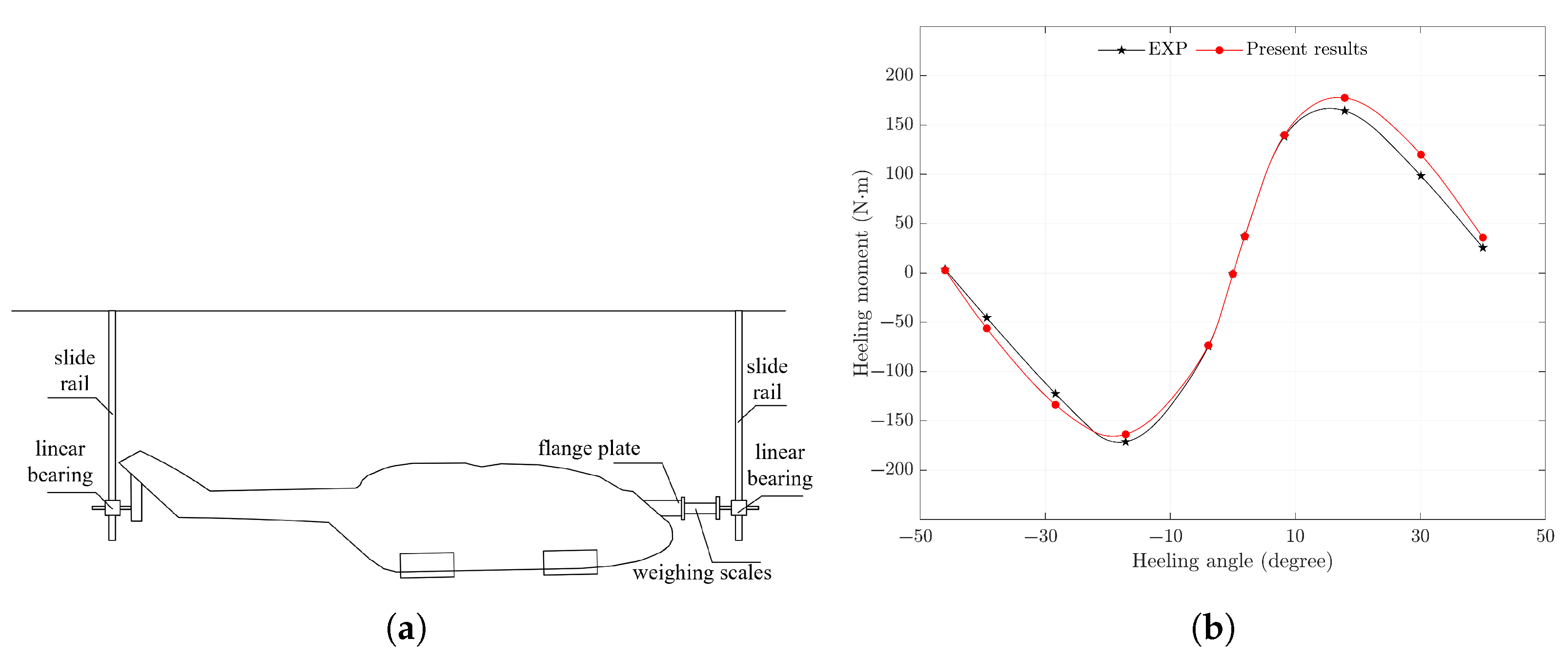
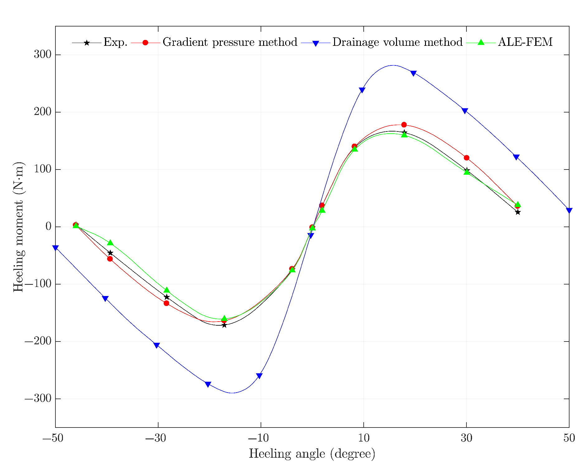
5.2. Lateral Static-Stability Results for the Flexible Model
For a helicopter model incorporating flexible airbags and connecting straps, the lateral static stability was analyzed using the gradient pressure method. The calculated results were then compared with those obtained from the arbitrary Lagrangian–Eulerian (ALE) method, experimental data, and the drainage volume method to validate the accuracy of the Gradient pressure method. Additionally, the discrepancies in the static-stability results were examined, with particular attention given to the influence of airbag and connecting-strap flexibility.
Based on existing experimental data, this study calculated the heeling moments at heeling angles of
,
,
,
,
,
,
,
,
,
, and
.
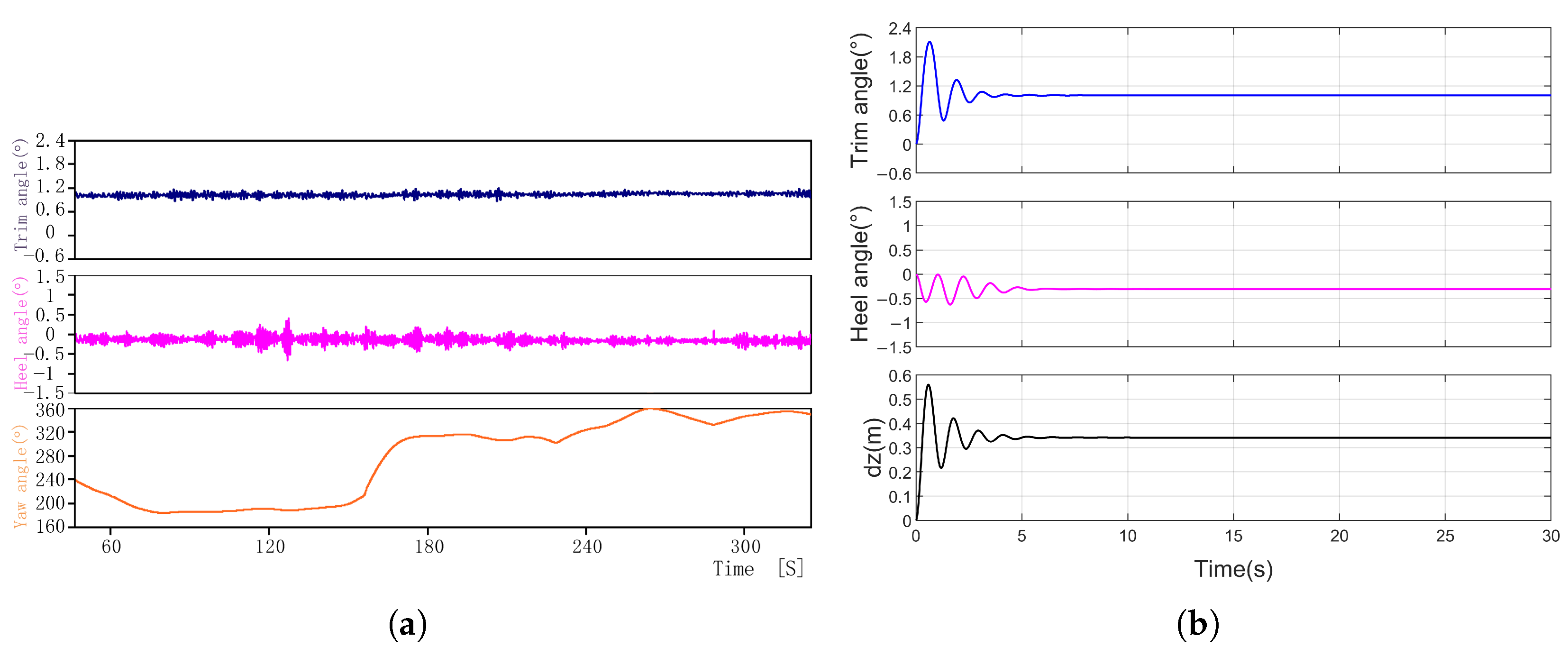
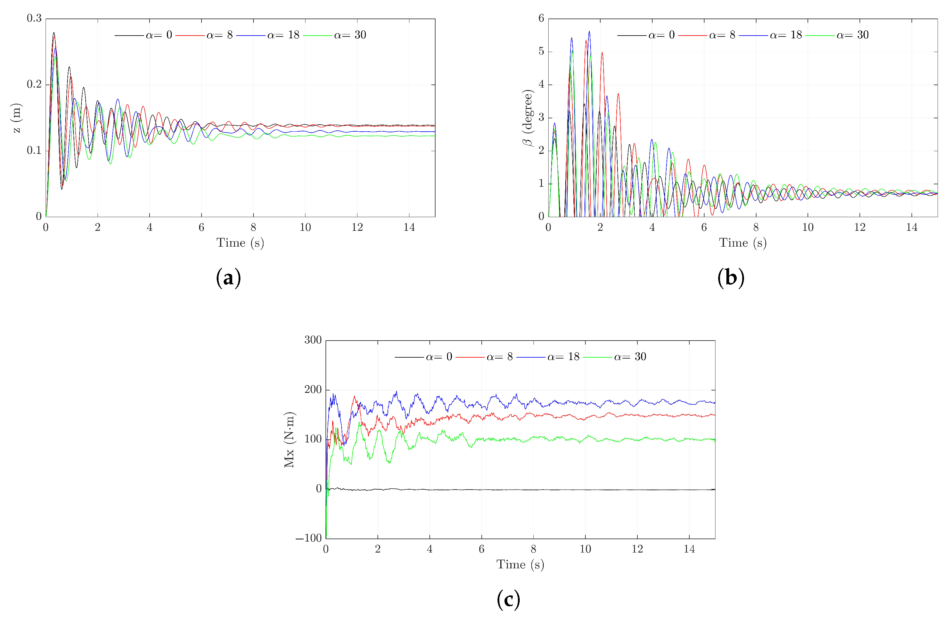
Figure 13 presents the time history results of the helicopter at
,
,
, and
. The observation results indicate that the helicopter reaches equilibrium at approximately 12 s. As the heeling angle increases, the height of the helicopter’s center of gravity above the water surface decreases. However, regardless of the heeling angle, the presence of short wings causes the helicopter’s center of gravity to remain positioned farther aft relative to the centroid. As the heeling angle increases, the longitudinal (x-direction) distance between the center of gravity and the centroid remains relatively constant. Therefore, as shown in
Figure 12, when the helicopter reaches equilibrium, its pitch angle is positive and is approximately the same across different heeling angles.
Figure 14 shows the heeling moment at different heel angles. Similar to the static-stability curve of the pure rigid model discussed in the previous section, the helicopter’s lateral static-stability moment is not zero at a heeling angle of
due to a
offset between the center of mass and the centroid in the y-direction. Within the small heeling angle range, the curve obtained using the drainage volume method closely resembles the static-stability results of the pure rigid model, displaying a proportional relationship between the heeling moment and heeling angle. In contrast, the results from the experiment, ALE-FEM simulation, and the gradient pressure method deviate from linearity in this range. This difference arises because even under small heeling angles, the airbags possess vertical and rotational degrees of freedom relative to the helicopter. Consequently, after the system reaches equilibrium, the airbags tend to maintain a near-horizontal posture, resulting in vertical displacements, drainage volumes, and buoyancy centers similar to those at the
roll angle. As a result, the heeling moments differ from those predicted by the rigid-body-based drainage volume method. Additionally, the helicopter reaches a zero heeling moment at lower heeling angles in the experiment, ALE-FEM, and gradient pressure method compared to the drainage volume method. Due to the vertical and lateral degrees of freedom, the airbags are able to move closer to the helicopter’s body. For a given buoyant force, this reduces the moment arm provided by the airbags. Therefore, compared to the rigid model, the effective width of the system’s lower structure is significantly reduced, and the overall buoyancy center coincides with the system’s center of gravity in the y-direction at smaller roll angles.
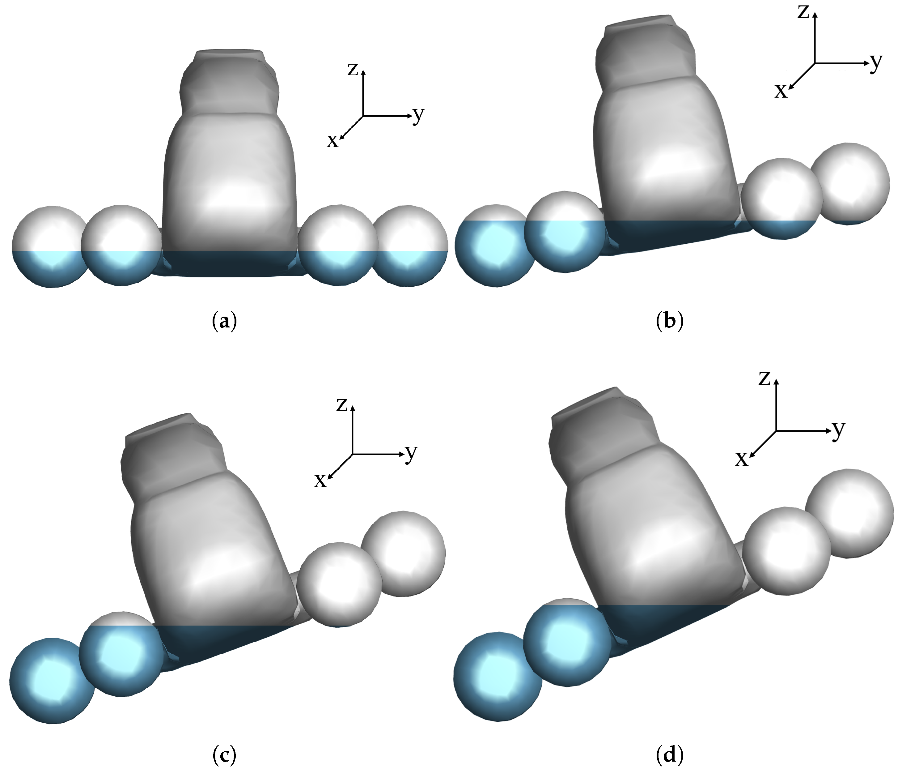
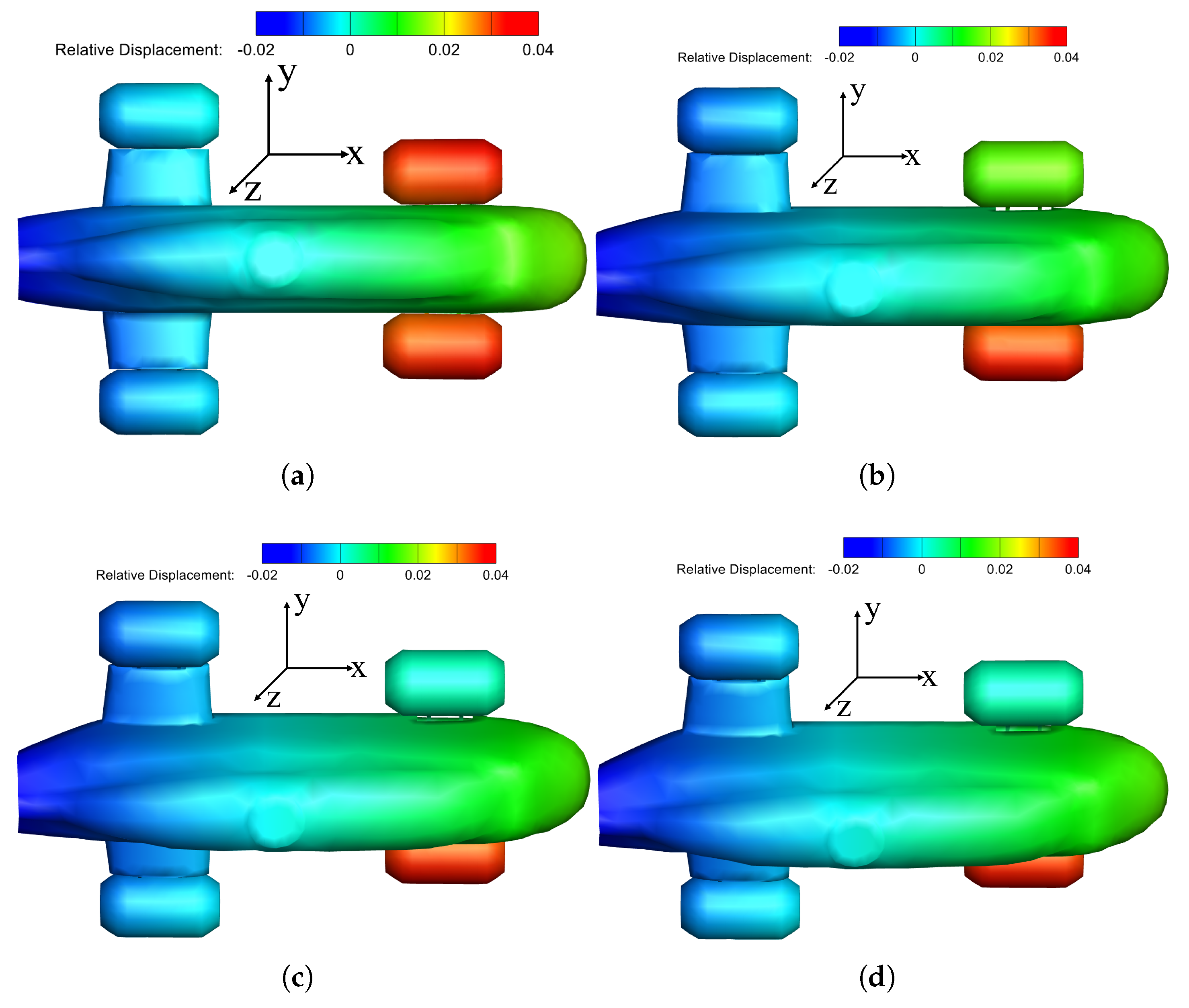
Figure 15 shows the waterline heights at different heeling angles. The gray area indicates the portions of the helicopter and airbags located above the waterline, which are fully exposed to the air, while the blue area represents the portions below the waterline, which are completely submerged in water. Specifically, airbag 4 becomes fully submerged at the heeling angles of
and
. Each airbag has a volume of 0.0242
, contributing approximately one-quarter of the helicopter’s total buoyant force. As the heeling angle increases from
to
, the y-direction distances from airbag 2 and airbag 4 to the helicopter’s center of gravity change from 0.3423 m and 0.5706 m to 0.3177 m and 0.5196 m, respectively. These changes alter the static-stability moments generated by airbags 2 and 4, resulting in a reduction in overall stability.
Figure 16 shows the cloud map of the z-direction displacement of the relative center of gravity of nodes when the helicopter is in a stable state. At a heel angle of
, all four experience vertical upward buoyancy forces from the water. As shown in
Figure 16, when the heel angle increases above
, airbags 1 and 2 exhibit different relative displacement. Since airbag 1 is no longer subjected to buoyant force from the water, it sinks under its own weight.
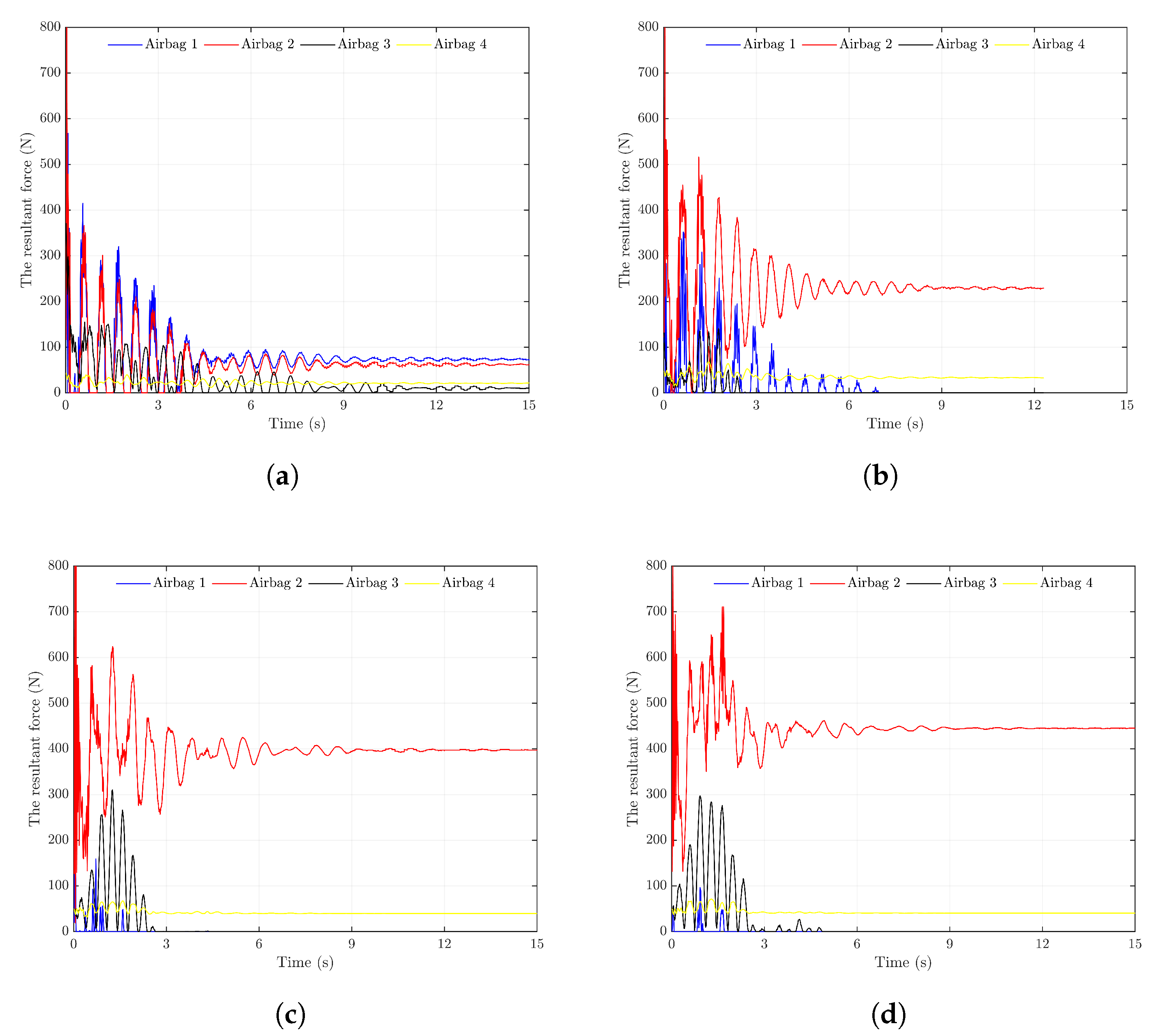
Figure 17 presents the time history of the contact force between the helicopter and each airbag at heeling angles of
,
,
, and
. Based on the results shown in
Figure 16, the following observations can be made: When the heeling angle is
, due to the geometric symmetry of the helicopter system, the contact forces on airbags 1 and 2 (located at the front of the helicopter) are similar, as are those on airbags 3 and 4 (located at the rear). Furthermore, because the front airbags are embedded within the fuselage while the rear airbags are mounted on short wings, the contact area between the front airbags and the fuselage is larger than that of the rear airbags. As a result, the front airbags experience significantly greater contact forces than the rear ones.
When the heeling angle is , airbags 1 and 3, which are positioned on the lifted side of the helicopter, are raised above the water surface. Due to the small mass of each airbag (approximately 0.71 kg), the contact forces between these two airbags and the helicopter are primarily attributable to their own weight. Consequently, as the floating system reaches equilibrium, the contact forces from airbags 1 and 3 tend toward zero. On the opposite side, airbags 2 and 4 move downward. Subjected to the weight of the helicopter, the drainage volumes of these airbags increase, resulting in greater buoyant forces and thus larger contact forces. Additionally, since airbag 2 is positioned farther from the helicopter’s roll axis than airbag 4, it becomes more deeply submerged. As a result, the contact force from airbag 2 is significantly greater than that of airbag 4. Therefore, compared to the heel condition, the contact forces between the helicopter and airbags 2 and 4 increase noticeably when the heeling angle is .
When the heeling angles reach
and
, the relative positions of each airbag with respect to the helicopter are similar to those observed at
. Consequently, the resulting contact forces between each airbag and the helicopter also exhibit patterns similar to those at the
heeling angle. By examining the contact force variation curves in
Figure 17a–d, it can be seen that as the heeling angle increases, the drainage volume of the submerged airbags increases correspondingly. This leads to a gradual rise in the contact forces exerted by airbags 2 and 4 on the helicopter. Therefore, in the design of helicopter flotation systems, it is essential to account for the deformation of airbags under large contact forces at high heeling angles and to ensure the airbags’ structural safety under such conditions.
In summary, based on the preceding analysis and experiment results, it is evident that the flexibility of airbags and connecting straps must be considered when calculating the lateral static stability of a helicopter equipped with floating systems. Ignoring these effects leads to an overestimation of the static stability. The reasons for this overestimation are as follows:
- (1)
Flexible deformation of airbags. Under the influence of water pressure and contact force from the fuselage, the airbags undergo compression, which reduces their volume. This, in turn, decreases the amount of water displaced on both sides of the helicopter, leading to a reduction in static stability. Therefore, if airbag flexibility is not accounted for, the resulting lateral static stability will be overestimated.
- (2)
Flexible deformation of connecting straps. The airbags are connected to the helicopter via multiple connecting straps, and an initial gap exists between the airbags and the fuselage. When the flexibility of the connecting belts is considered, the airbags move upward relative to the fuselage due to water pressure, reducing airbag displacement and increasing the fuselage’s immersion. This shift results in decreased static stability. Furthermore, the relative movement of the airbags toward the fuselage closes the initial gap, causing the centroid of the displaced water volume of the airbag to move closer to the fuselage, further reducing static stability. Therefore, neglecting the flexibility of the connecting straps leads to an overestimation of lateral static stability.
5.3. Effects of Airbag Internal Pressure on Lateral Static Stability
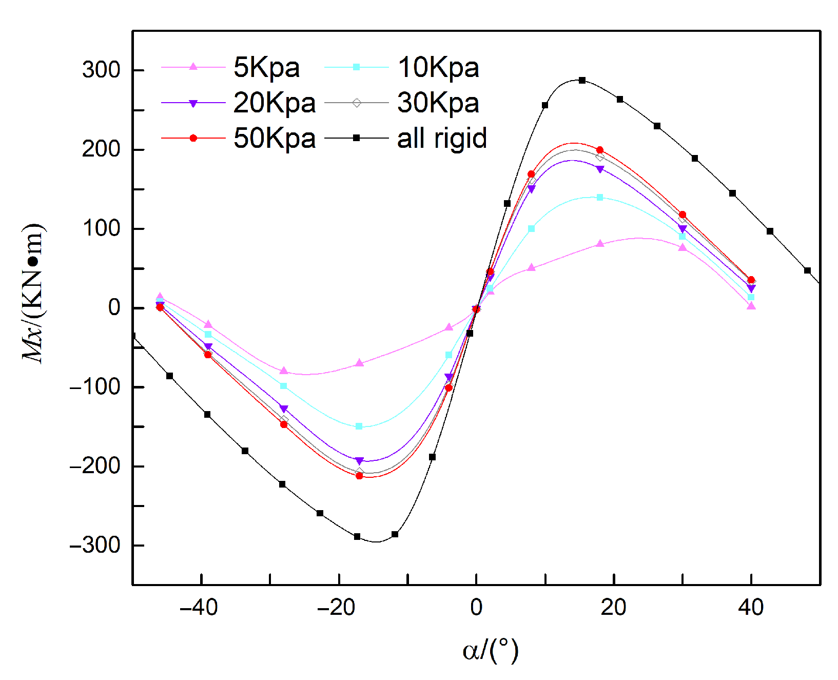
Based on the above conclusions, the variation in lateral static stability of helicopters, which is caused by the flexibility of airbags and connecting straps, is primarily attributed to the elastic behavior of the airbags themselves, specifically the influence of the airbag’s internal pressure. In this section, 5 kPa, 10 kPa, 20 kPa, 30 kPa, and 50 kPa (relative to standard atmospheric pressure) are selected as parameters of airbag internal pressure to analyze the impact of airbag deformation on the lateral static stability of the helicopter.
As shown in
Figure 18, this paper calculates the static-stability curves of the airbag under internal pressures of 5 kPa, 10 kPa, 20 kPa, 30 kPa, and 50 kPa.
It can be observed that as the internal pressure of the airbag increases, the lateral static stability of the helicopter improves, and the heeling angle corresponding to the maximum heeling moment tends to decrease. When the internal pressure of the airbag is 5 kPa, the airbag undergoes significant deformation, resulting in reduced static stability. In contrast, when the internal pressure of the airbag is 30 kPa and 50 kPa, the static-stability results of the helicopter are similar, indicating that airbag deformation becomes negligible beyond 30 kPa. Furthermore, by comparing the results at 50 kPa with those of the rigid-body model, it is evident that whether the flexibility of the connection straps is considered has a substantial impact on the calculated lateral static stability of this helicopter model.


