Article

A Novel Shape Memory Alloy Actuated Bearing Active Preload System (SMA-BAPS) for Space Spindles

1
Beijing Institute of Control Engineering, Beijing 100190, China
2
School of Energy and Power Engineering, Beihang University, Beijing 100191, China
3
Beijing Key Laboratory of Aero Engine Structure and Strength, Beijing 100191, China
*
Author to whom correspondence should be addressed.
Aerospace 2025, 12(7), 637; https://doi.org/10.3390/aerospace12070637
Submission received: 29 May 2025 / Revised: 6 July 2025 / Accepted: 14 July 2025 / Published: 17 July 2025
(This article belongs to the Section Astronautics & Space Science)

Abstract

In this study, a novel shape memory alloy actuated bearing active preload system (SMA-BAPS) was proposed and experimentally demonstrated. SMA actuators placed in a single or antagonistic configuration were employed to drive the screw pair and thus fulfill one-way or bidirectional preload adjustment. Moreover, the self-locking screw pair was used to maintain the bearing preload without external energy input. To determine the parameters of screw pair and SMA actuators, a detailed design process was conducted based on analytical models of the proposed system. Finally, a screw pair with a lead of 3 mm and SMA actuators with a diameter of 0.5 mm and a length of 130 mm were adopted. Prototype tests were conducted to validate and evaluate the performance of the preload adjustment with the SMA-BAPS. The resistive torque and the natural frequency of spindles were recorded to represent the preload level of the bearing. Through the performance tests, the SMA-BAPS induced a maximum 47% variation in the resistive torque and a 20% variation in the spindle’s natural frequency. The response time of the SMA-BAPS was less than 5 s when the heating current of 5 A was applied on the SMA actuator. This design highlighted the compact size, quick response, as well as the bidirectional preload adjustment, representing its potential use in aerospace mechanisms and advanced motors.

1. Introduction

Bearing performances have a significant influence on the stiffness and the rotary accuracy of space spindles [1,2,3,4,5]. When assembled, the paired bearings are preloaded to eliminate clearance as well as to provide a defined stiffness for the spindle. Ordinarily, a sufficiently high preload is employed to protect the paired bearings from offloading or hammering during launch [6]. However, with the applied bearing preload, a highly resistive torque is induced during on-orbit operation, resulting in a low bearing life and high consumption. In order to adjust the bearing preload on orbit and improve the performances of space spindles, bearing preload adjustment technologies for space spindles must be developed.
For high-speed spindles on the ground, researchers have developed many preload adjustment systems based on hydraulic [7,8] or pneumatic [9] devices, electromagnetic actuators [10,11], piezoelectric actuators [12,13,14], and centrifugal forces [15,16]. However, these systems cannot be integrated into space spindles due to large sizes, complicated structures, susceptibility, and high cost. In recent years, a few studies on the specialized preload adjustment systems for space spindles have been conducted. Lewis et al. [6,17,18] designed and qualified a bearing active preload system (BAPS) that aims at preload adjustment on-orbit. The key component of their BAPS was a monolithic structure driven by a shape memory alloy (SMA) plate actuator. Owing to the bistable characteristic, the BAPS they proposed represented good practicability and reliability, but the hollow-out design lowered the axial stiffness of spindles. Florian et al. [19] and Thomas et al. [20] utilized a circle array of SMA rods to unload the bearing preload and carried out a full qualification test sequence. The response time of the unloading mechanism was quite long as a result of the heat conduction of the overall structure. Moreover, low-temperature grinding must be adopted to machine the SMA rods to the desired length. Compared to SMA plates or rods, SMA wire actuators show the characteristics of quick response and flexibility. Furthermore, bidirectional actuation could be achieved by antagonistic SMA wire actuators, and this extends the capability of previous studies, which only allowed for the one-way preload adjustment.
As described above, there is a need for a specialized BAPS with the characteristics of two-way preload adjustment and quick response. The present study proposes a novel SMA-BAPS, which could be applied in hard preload spindles as well as other aerospace mechanisms. Single or antagonistic SMA wires are employed to actuate the self-locking screw pair, contributing to the compact and easily integrated structure as well as the quick, bidirectional, and efficient actuation response. Then, lumped models of the proposed SMA-BAPS configuration are established to analyze and estimate the capability of preload adjustment, the self-locking of screw pairs, and the actuation process of SMAs. Moreover, the design parameters are determined based on the analytical model. Finally, the prototype of the SMA-BAPS is fabricated and tested. Qualification experiments are developed to evaluate the performance of the preload adjustment. A maximum 47% variation in resistive torque and a nearly 20% variation in natural frequency are observed through the preload adjustment. The response time of the preload adjustment is less than 5 s with the electric current of 5 A for the SMA wire actuator.
The novelty and the contributions are summarized as follows: (a) A novel mechanism configuration is proposed to fulfill the bidirectional and quick preload adjustment. (b) The analytical model of SMA-BAPS is established and the detailed design process is conducted. (c) A prototype of the proposed SMA-BAPS is developed and the performance of preload adjustment is qualified and evaluated.
The remainder of this paper is organized as follows. In Section 2, the concept of design and the operation principle of the proposed SMA-BAPS are provided. Then Section 3 gives the modeling work that quantifies the preload adjustment ability as well as the design process of the screw pair and the SMA actuator. Experimental investigations that describe the performance of the proposed system are presented in Section 4. Finally, a conclusion is drawn in Section 5.

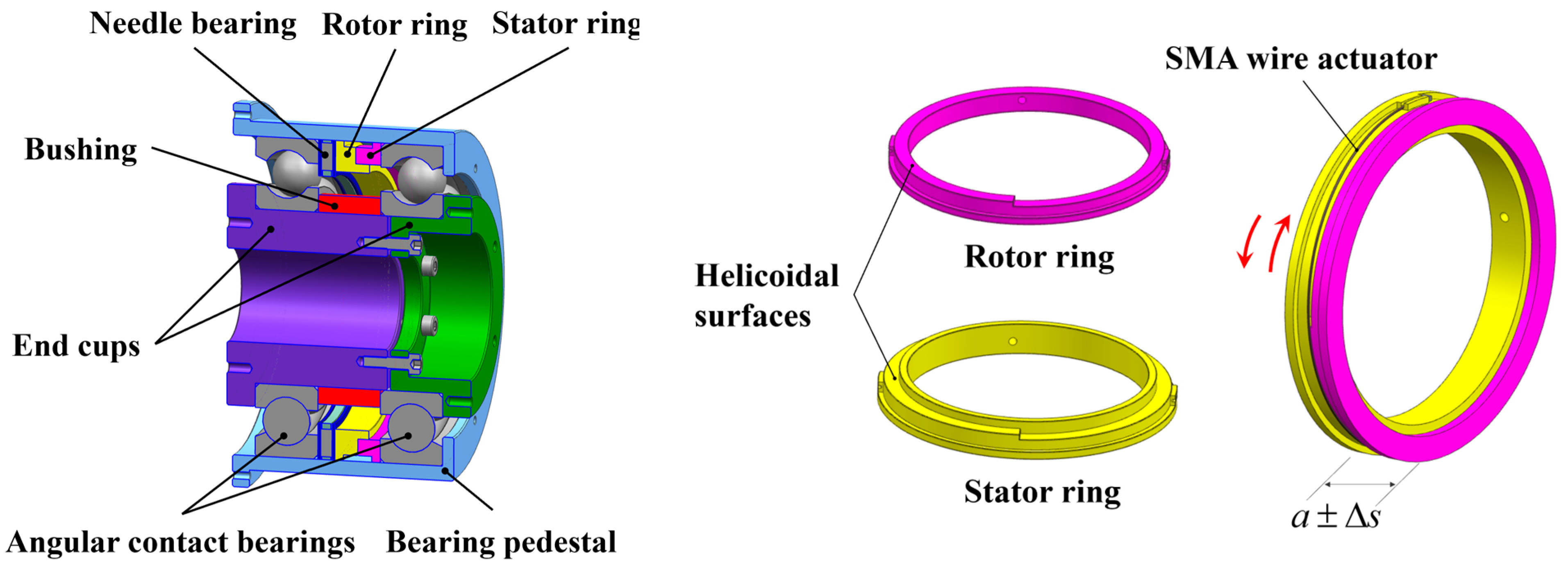
2. Concept Configuration and Operation Principle

Figure 1 shows the schematic diagram of the SMA-BAPS. A screw pair composed of a rotor ring and a stator ring is placed between the outer rings of the paired bearings. As the rotor ring is driven to rotate, the axial length of the screw pair is changed, as illustrated in Figure 1. Moreover, a needle roller thrust bearing is placed next to the rotor ring to reduce rotational friction. In order to actuate the rotation of the rotor ring, SMA wire actuators are wrapped around the outer of the screw pair and enclosed by a PTFE capillary tube to ensure insulation during electric heating, as shown in Figure 2. SMA actuators are placed in a single or antagonistic configuration to achieve one-way or reciprocated motion. The end of the SMA wire actuator is electrically insulated through a Polyimide shim. A cylindrical bearing housing is employed to support the paired bearings and the screw pair. There are two symmetrically distributed square holes at the bearing housing, which are used to lead out the conducting wire of the SMA actuator as well as check the rotation of the rotor ring. When tightening the bolts between the two end caps, a pressure load is applied to the inner rings of the paired bearings. One part of the pressure load undertaken through the balls acts as the bearing preload, while the other part is transmitted by a bushing. The end faces of the bushing are grinded precisely to control the axial length of the bushing, as mentioned in [6,21].
The operation principle of the SMA-BAPS is described as follows. When the system is assembled, the bearing preload is applied through the screw pair and the screw pair maintains the preload due to the self-locking of the helicoidal surfaces. Under this condition, the environment temperature should be less than the transformation start temperature (As) of the SMA. Obviously, the thermal control techniques are required to maintain the spindle temperature in practical applications. As a different preload state is needed, the SMA wire actuator is electrically activated to rotate the rotor ring. Thus, the screw pair is axially displaced by tens of microns, and the bearing preload is adjusted.

3. Design of SMA-BAPS

The design process of the SMA-BAPS is illustrated in Figure 3. First, the angular contact ball bearing used in the spindles resolves the adjustment range of the bearing preload. Then the screw pair is designed, and the need for driving force and displacement are thus determined. Moreover, the geometric parameters of the SMA wire actuator are designed. Considering the response time and power supply, the electrical parameters of SMA are selected finally.

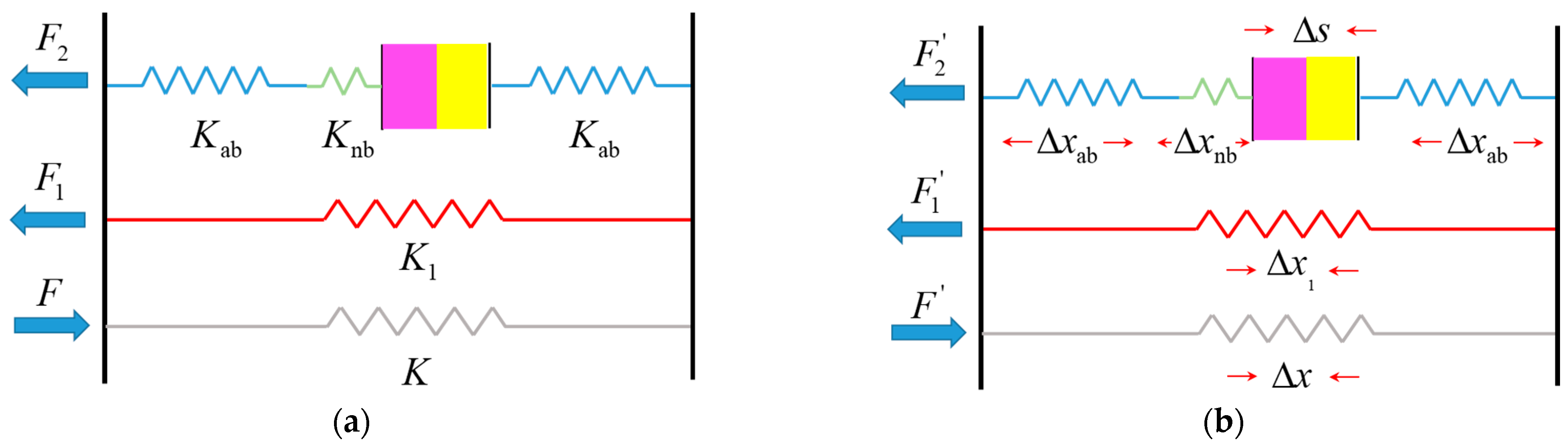
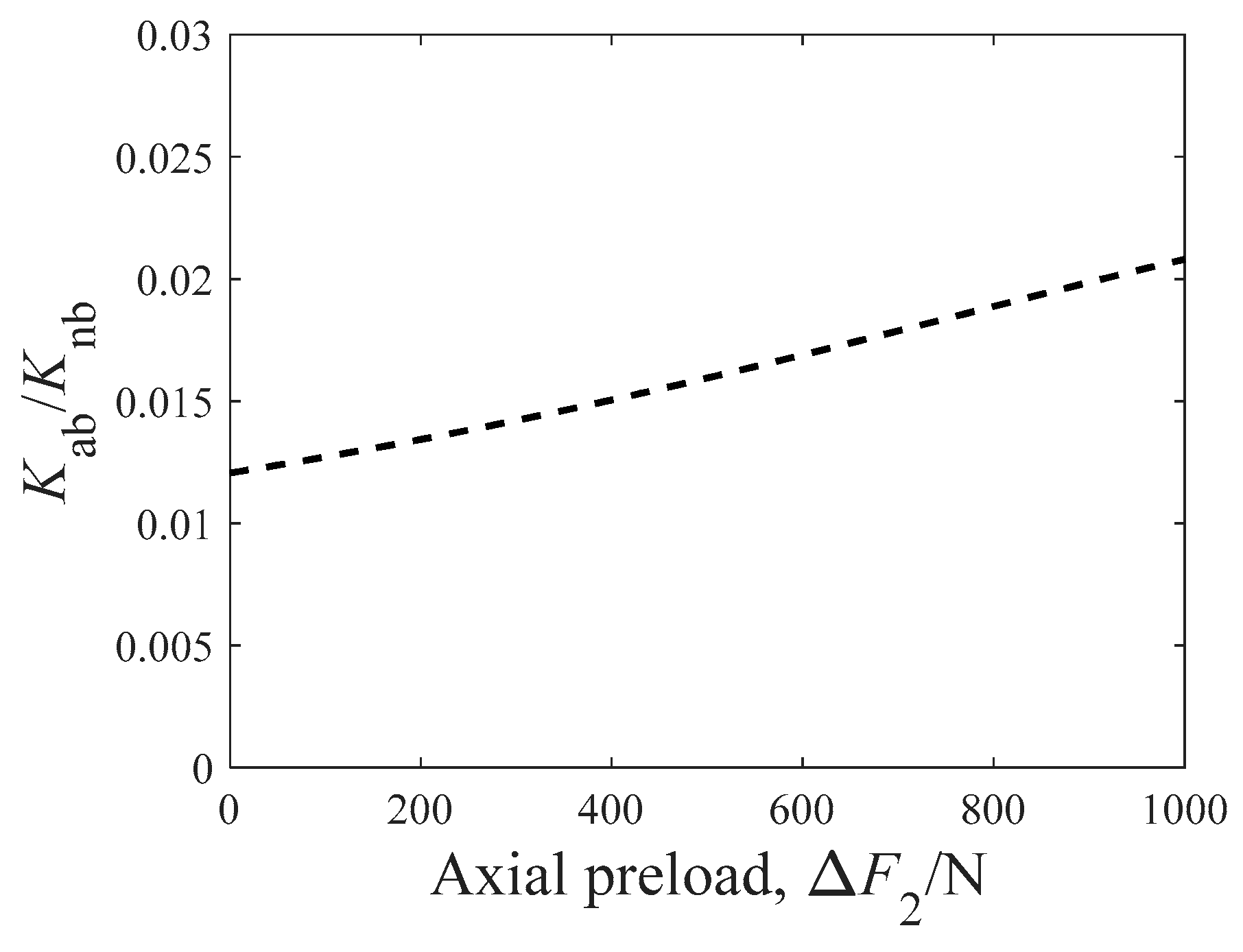
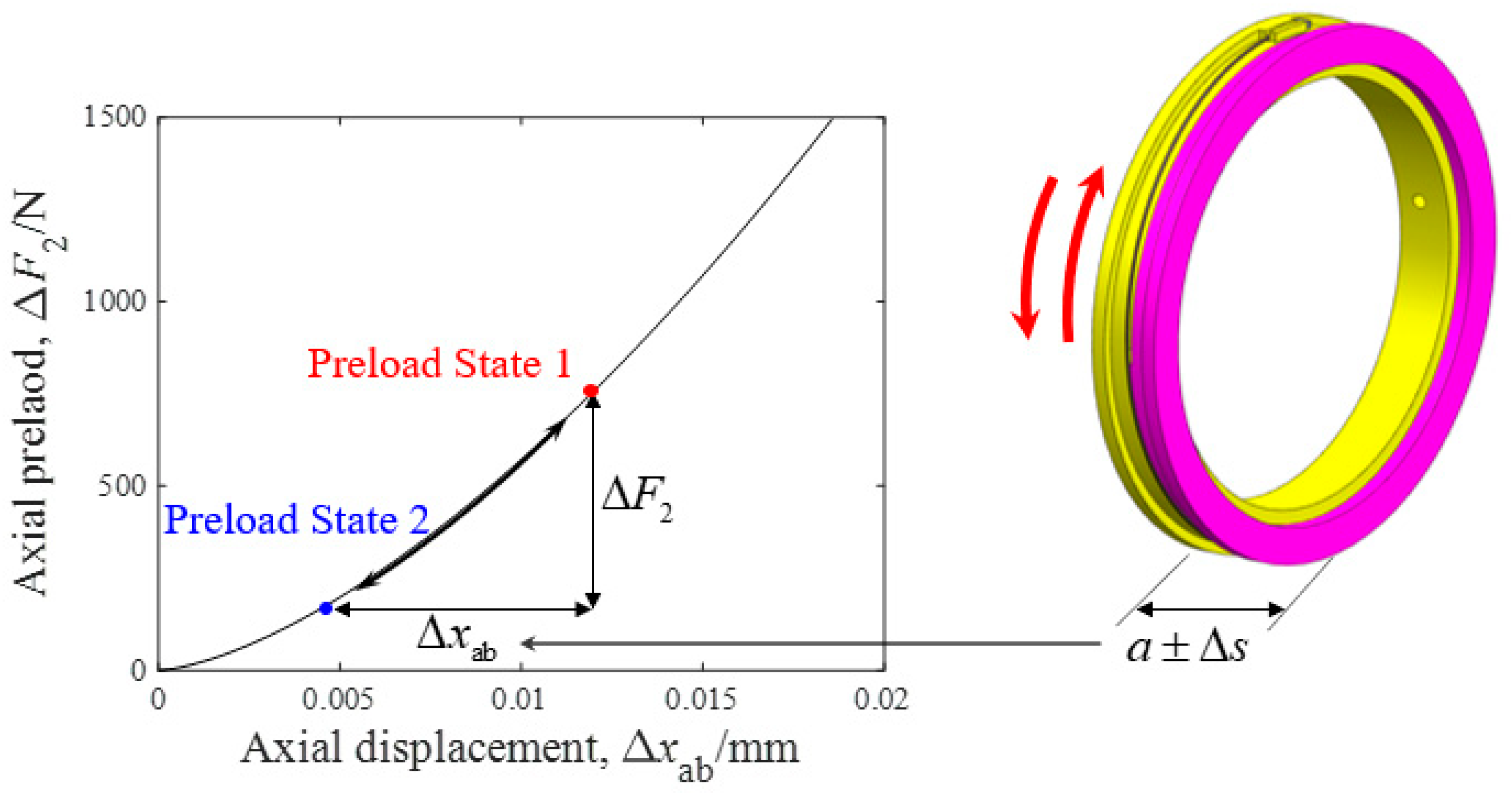
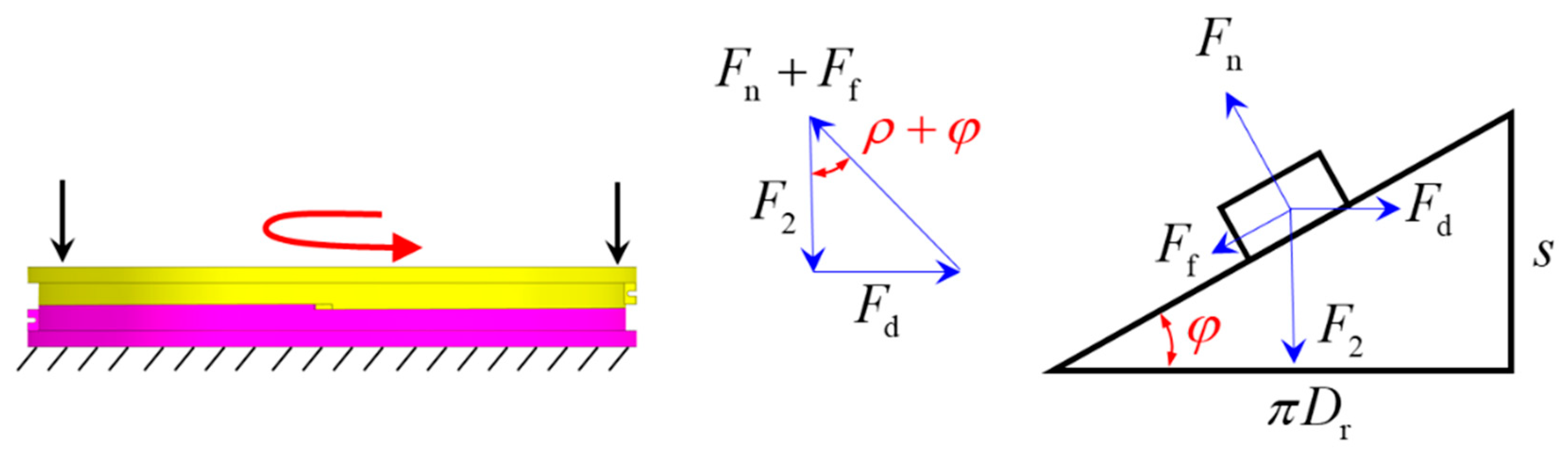
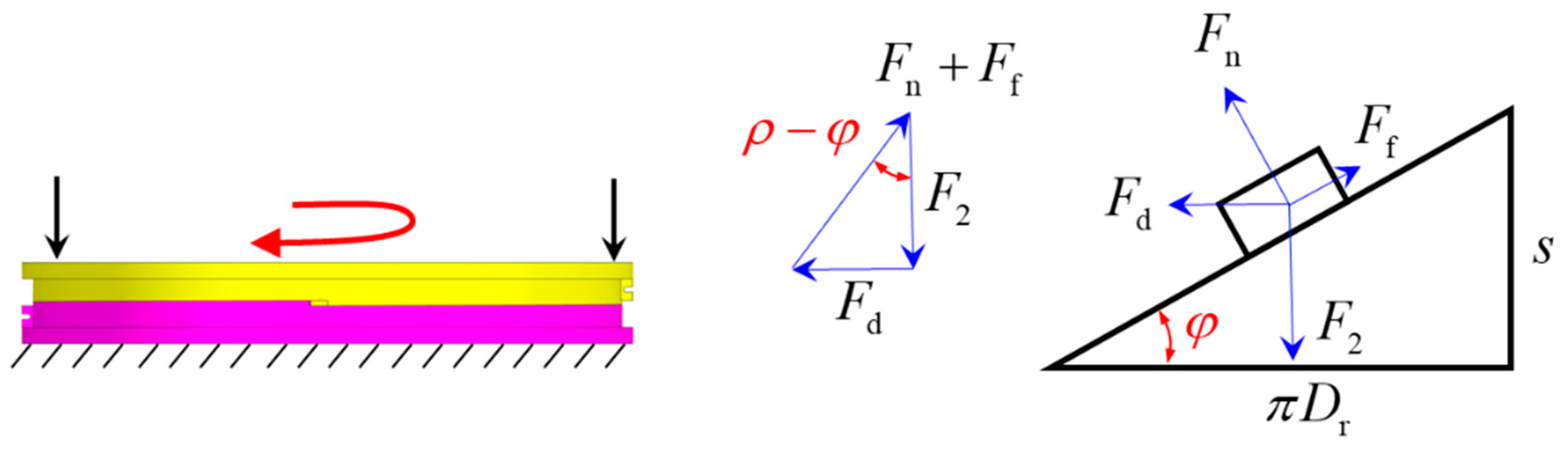
3.1. Preload Adjustment Analysis

Figure 4 shows an analytical model that describes component deformation in the SMA-BAPS. F, F1, and F2 are the compressive load generated by the bolts, the load transmitted by the bushing, and the bearing preload, respectively. Assuming that the length variation in the screw pair is small, the stiffness of the components of SMA-BAPS is constant. Then F, F1, and F2 are rewritten as follows:
F = F K Δ x F 1 = F 1 + K 1 Δ x 1 F 2 = F 2 K ab Δ x ab = F 2 K nb Δ x nb
where K, K1, Kab, and Knb are the stiffness of the bolts, the bushing, the angular contact ball bearing, and the needle roller thrust bearing, respectively. Moreover, assuming that Δs is the length variation in the screw pair, the deformation variation in the angular contact ball bearing is formulated as follows:
Δ x ab = Δ s K ab K + K 1 + K ab K nb + 2
Obviously, Δxab determines the range of the bearing preload adjustment. To evaluate the variation in the bearing preload with a given Δs, the stiffness expressions (K, K1, Kab, and Knb) are analyzed in the following.
According to the Hertz contact theory [1,2], the axial displacement δa of the angular contact ball bearing is derived from the normal displacement δn, which is given by the following:
δ a = δ n sin α + ( f i + f o 1 ) D w 1 ( sin α sin α 0 )
Using Equation (3), the axial stiffness characteristic of the angular contact ball bearing is calculated. In this paper, the 7212ACTA ball bearing is used in the BAPS and the parameters of the bearing are listed in Table 1.
The axial stiffness characteristic of the needle roller thrust bearing is calculated as [1] follows:
ζ a = 2 × 3.84 × 10 5 ( F a / Z 2 ) 0.9 l 0.8
where ζ a represents the axial displacement of the needle roller thrust bearing, and Fa is the load applied on the thrust bearing. The related parameters are listed in Table 2.
With Equations (3) and (4), Kab/Knb is calculated and shown in Figure 5. As the bearing preload varies from 0 N to 1000 N, the following relationship of Kab/Knb is further achieved:
K ab K nb < 0.02
So, the term Kab/Knb in Equation (2) is neglected in the modeling process. As for the stiffness of the bolts and the stiffness of the bushing, which are denoted as K and K1, they are evaluated through the methods described in previous studies [22,23,24]. Obviously, the order of magnitude of K and K1 is the same as the stiffness of the surface contact, while Kab is the stiffness of the point contact. Thus, K and K1 are much higher than Kab. As a result, Equation (2) is further simplified as follows:
Δ x ab = Δ s 2
Equation (6) implies that the deformation variation in the angular contact ball bearing is fully determined by the length variation in the screw pair, as shown in Figure 6.

3.2. Design of Screw Pair

Composed of the rotor ring and the stator ring, the screw pair acts as the key component for the preload adjustment. In order to undertake the bearing preload without sliding, the screw pair should meet the requirements for self-locking. As illustrated in Figure 7, the critical self-locking condition of the helicoidal surface is formulated as follows:
s < s c = π μ D r
where μ is the friction coefficient of the helicoidal surface and Dr is the outer diameter of the screw pair. According to Equation (7), sc is the maximum lead of the helicoidal surface under which the screw pair maintains the axial preload. Based on the bearing dimension, Dr is designed as 106 mm and a typical value of μ is selected as 0.15 in the design process. Considering Equation (7), two screw pairs with leads of 2 mm and 3 mm are fabricated. It is found that the screw pair with the lead of 3 mm expresses a high margin for preload adjustment. As a result, the lead of the screw pair is chosen as 3 mm and the processed screw pair is shown in Figure 8.
As the rotor ring is driven to rotate, the friction coefficient of the needle roller thrust bearing (typically by 0.01, oil-lubricated) is much lower than that of the helicoidal surface. Consequently, the resistance is mainly caused by the friction on the helicoidal surface. As illustrated in Figure 9 and Figure 10, the driving force Fd that rotates the screw pair is formulated as follows:
Uploading :   F d = F 2 tan ( ρ + φ )
Unloading :   F d = F 2 tan ( ρ φ )
With Equations (8) and (9), the required driving force to rotate the screw pair is evaluated, which further determines the diameter of the SMA wire actuator.
The processed screw pair was tested through the specific process, as demonstrated in Figure 11. First, the screw pair (lubricated by SKF LGHB2 grease) as well as the needle roller thrust bearing (oil-lubricated) were compressed axially in a tensile tester. As the axial load was varied from 100 to 700 N, the maximum driving force needed to unload the rotor ring was recorded through a tensometer. The test result is shown in Figure 11b and the maximum driving force was found to be linear with the axial load. Combing the test result with Equation (9), the friction coefficient for the processed screw pair was calculated as 0.12.

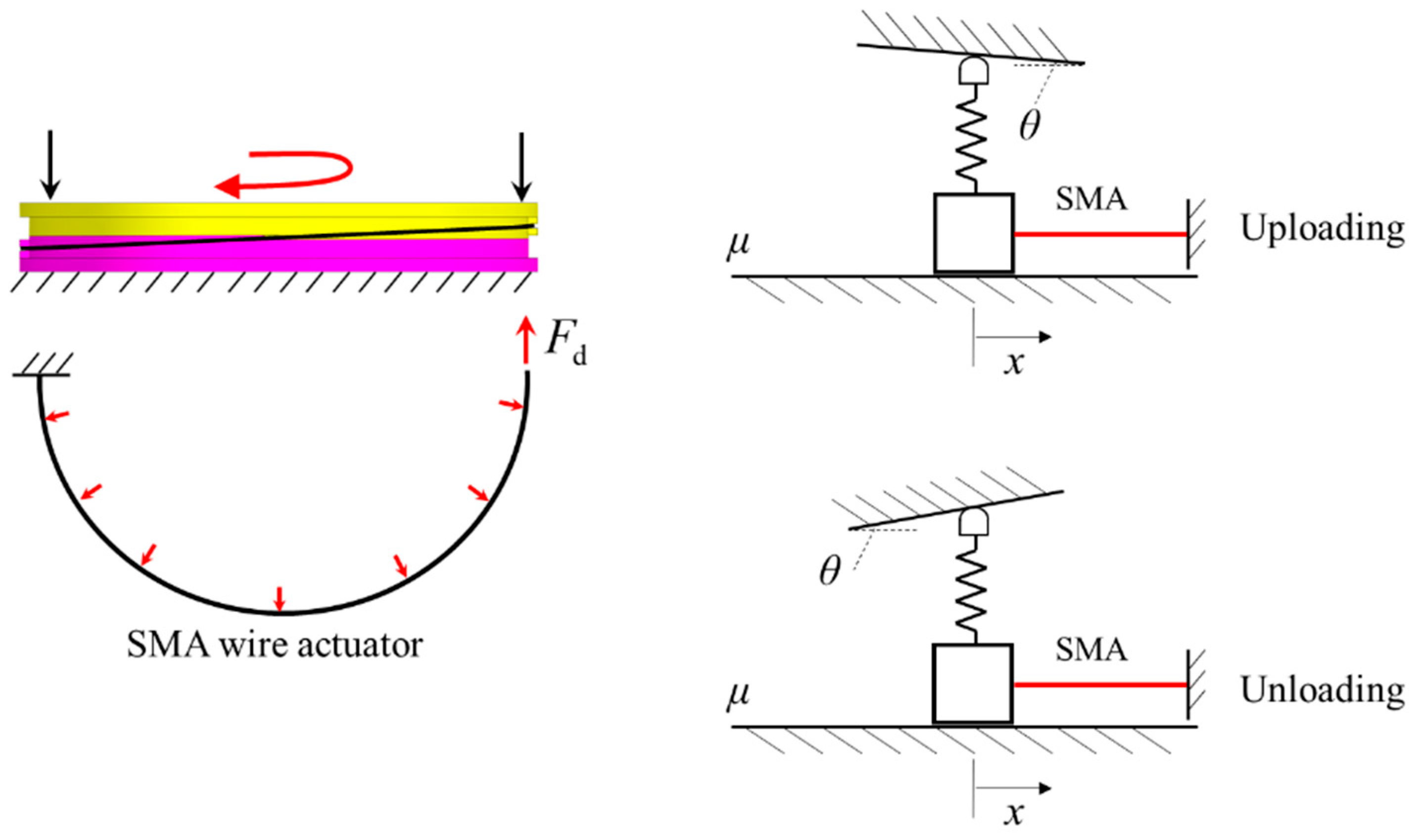
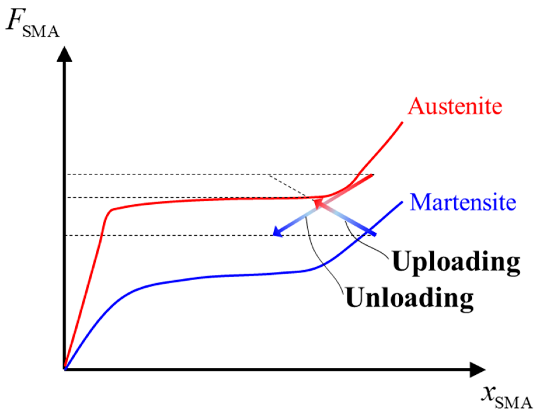
3.3. Design of SMA Actuator

SMA wire actuators are adopted to drive the screw pair in this study. When designing SMA actuators, three points must be considered. First, the output force of SMA actuator should be greater than the friction force of the screw pair. Second, the stroke of the SMA actuator is designed sufficiently to rotate the screw pair to the desired position. Third, the SMA is heated above the transformation start temperature to induce martensite transformation and generate force and stroke. In this section, single and antagonistic SMA actuators are both considered. The actuation path and the time–temperature response of SMA wire actuators are modeled to design the diameter, the length, and electrical heating parameters of SMA actuators.

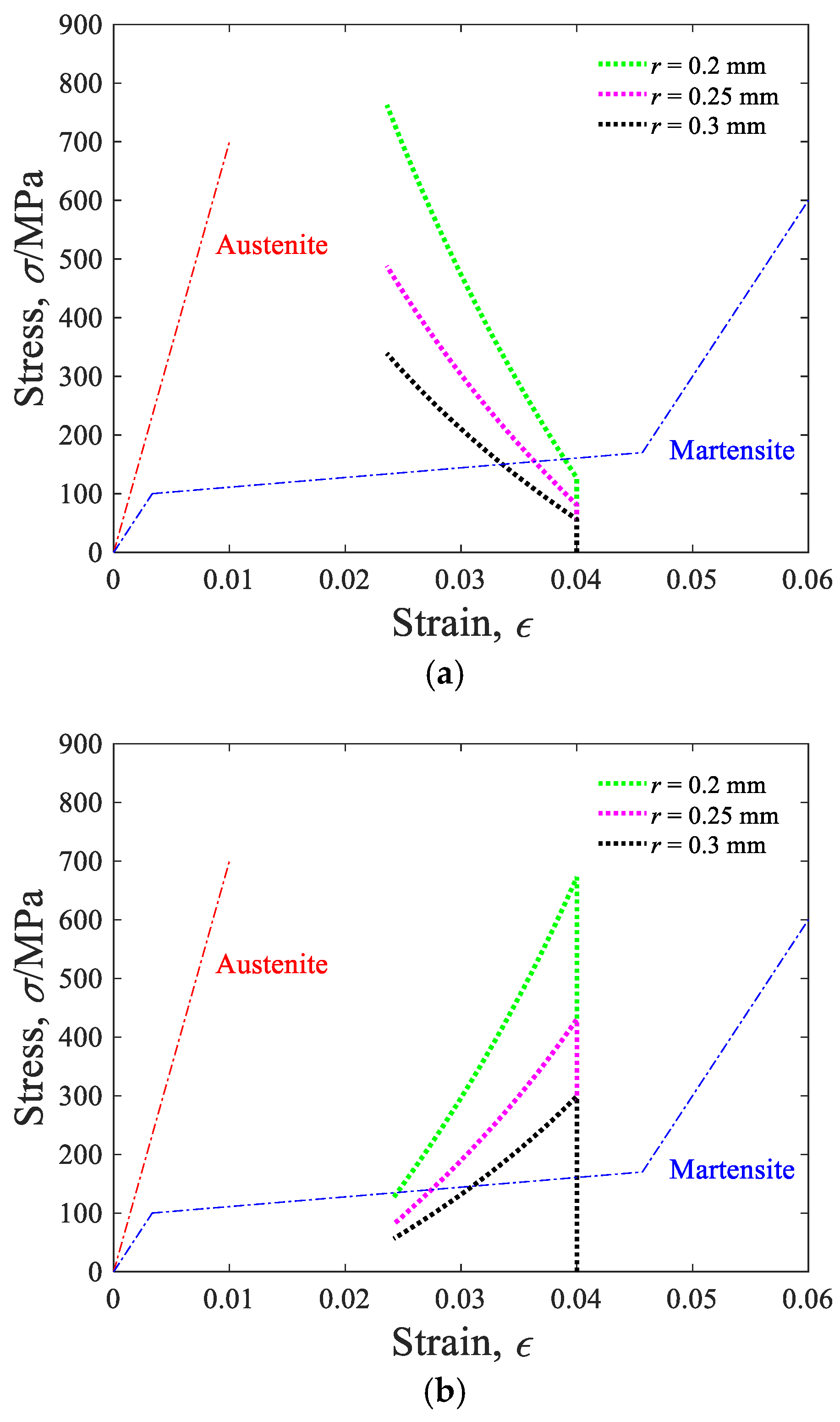
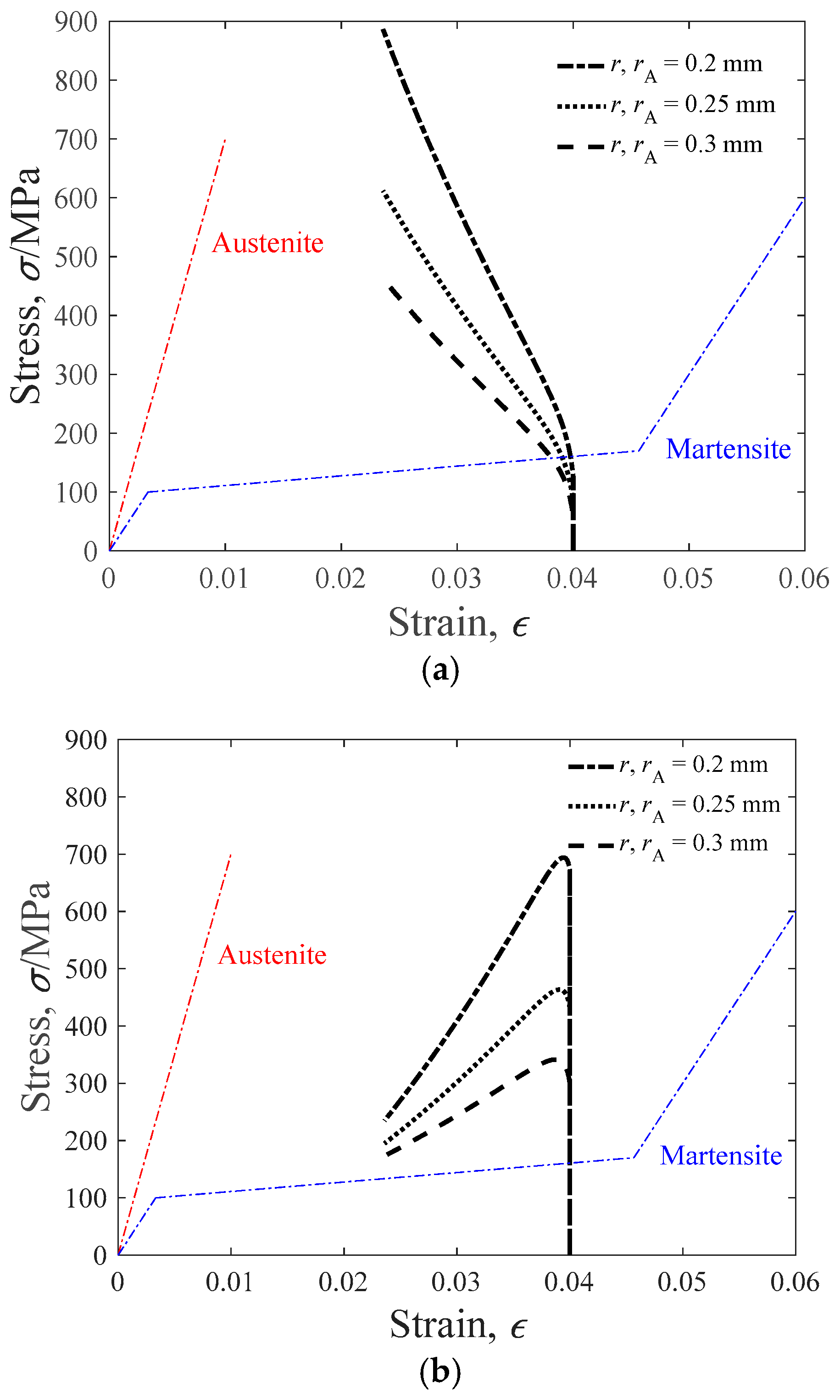
3.3.1. Determination of SMA Radius and Length

First, the actuation process of single arranged SMA actuators is considered. As shown in Figure 12, the spring and the bevel are adopted to simulate the characteristic of the bearing preload. The driving force of SMA wire is zero before actuating and then increases monotonously when applying a current on the SMA. As the driving force of the SMA reaches the critical friction, the slider starts to move right, which elongates/compresses the spring and thus adjusts the bearing preload. During the unloading and uploading process, the friction force of the screw pair decreases and increases, respectively, as the SMA actuator contracts.
As described above, the actuation of the SMA is divided into two steps. In the first step, the driving force of the SMA is less than the critical friction of the screw pair, and the slider remains stationary. As a result, the SMA actuator is completely constrained and the strain of the SMA is kept as constant. Then the driving force of the SMA reaches the critical force and the slider starts to move. The strain of the SMA is recovered as a result of martensite transformation. By combining Equations (8) and (9) with the bearing stiffness, the stress and the strain of the SMA actuator in the second step should be as follows:
Uploading :   π r 2 d σ d ε = L s tan ( ρ + φ ) 2 π D r d F 2 d s = L s tan ( ρ + φ ) K ab 2 π D r
Unloading :   π r 2 d σ d ε = L s tan ( ρ φ ) 2 π D r d F 2 d s = L s tan ( ρ φ ) K ab 2 π D r
where r is the radius of the SMA actuator, L is the length of the SMA actuator, and Kab is the stiffness of bearing that could be derived from Equations (6)–(9) in Section 3.1.
With Equations (10) and (11), the actuation path of SMA actuators with a variable radius is calculated, as shown in Figure 13. The preload adjusted range is from 100 N to 600 N and the reverse. The parameters of the SMA-actuated system are listed in Table 3. Before actuating, the initial strain of the SMA is assumed as the maximum transformation stain εL, and the initial stress is 0. It is found that the maximum stress occurs in the uploading process, which is 762 MPa, 488 MPa, and 339 MPa, with the radius of 0.2 mm, 0.25 mm, and 0.3 mm. With a larger radius, the stress level of the SMA actuator is relatively low when adjusting the bearing preload, and a high force margin can be achieved. However, a larger radius may result in a slow response and high energy consumption. As shown in Figure 14, the recovery strain of the SMA is dominated by the length of the SMA. When the length is equal to 100 mm, 130 mm, and 160 mm, the recovery strain is 0.0164, 0.0126, and 0.0102, respectively.
When SMA actuators are placed in an antagonistic configuration, reciprocal motion could be fulfilled. The resistance of the actuated SMA is composed of the friction and the tensile force of the biased SMA wire. It could be concluded that the antagonistic configuration changes the stress level of the actuated SMA actuator. As a result, Equations (10) and (11) are rewritten as follows:
Uploading :   π r 2 d σ d ε = L s tan ( ρ + φ ) K ab 2 π D r π r A 2 d σ A d ε
Unloading :   π r 2 d σ d ε = L s tan ( ρ φ ) K ab 2 π D r π r A 2 d σ A d ε
where rA and σA represent the diameter and stress of the biased SMA actuator. The stress and strain of the biased SMA are zero before actuating. The actuation paths of the uploading and unloading processes are shown in Figure 15. Compared with Figure 13, the maximum stress of the antagonistic SMA actuator increases by 120 MPa. Under high stress, the actuation performance of the SMA degrades because of the accumulation of plastic strain. According to the above, commercially available binary Ni49.8Ti50.2 (at. %) alloy wires with a diameter of 0.5 mm and length of 130 mm are used in this investigation (marketed by Grikin Advanced Materials Co., Ltd., Shenyang, China)

3.3.2. Electrical Parameter Design
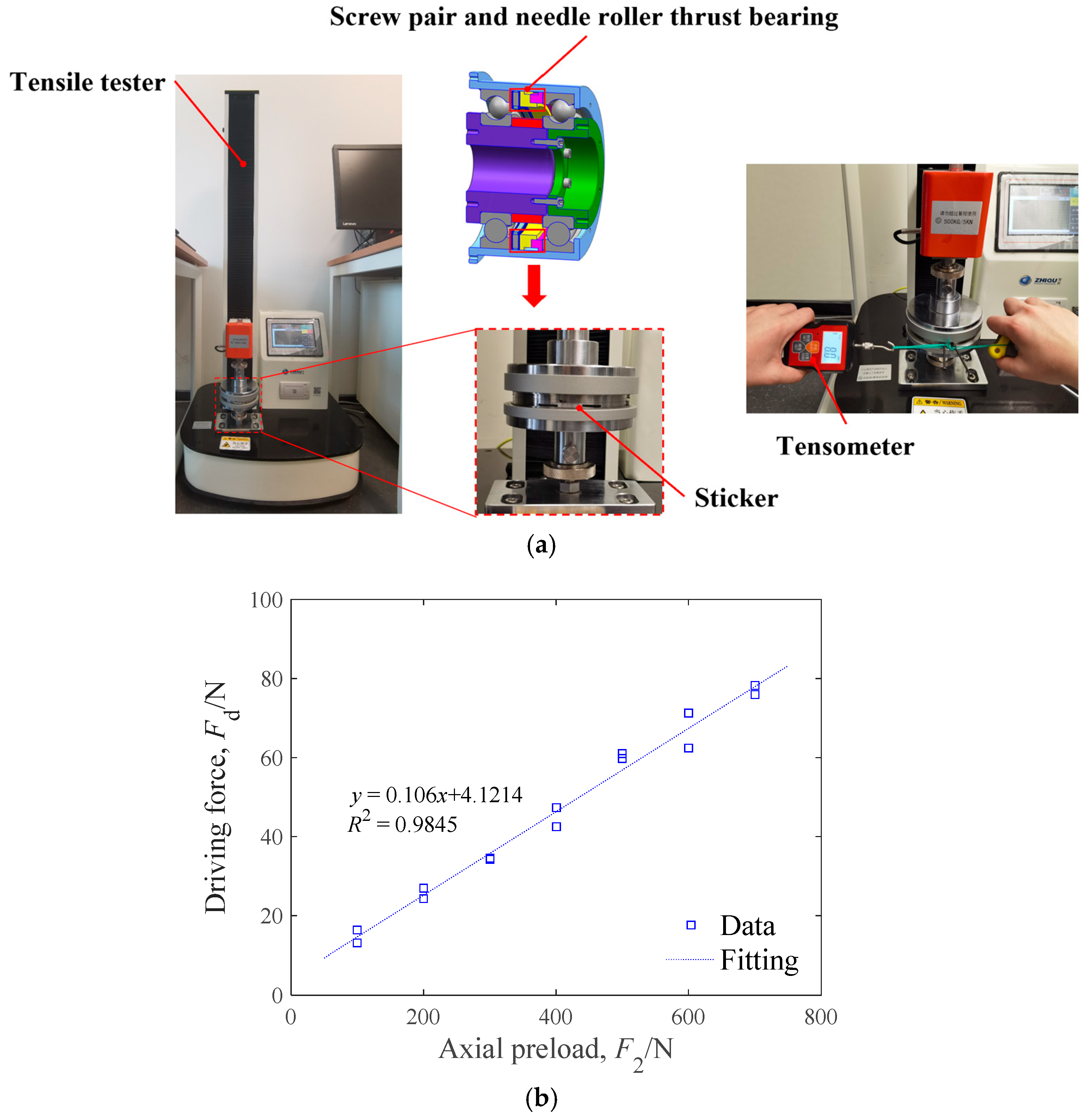
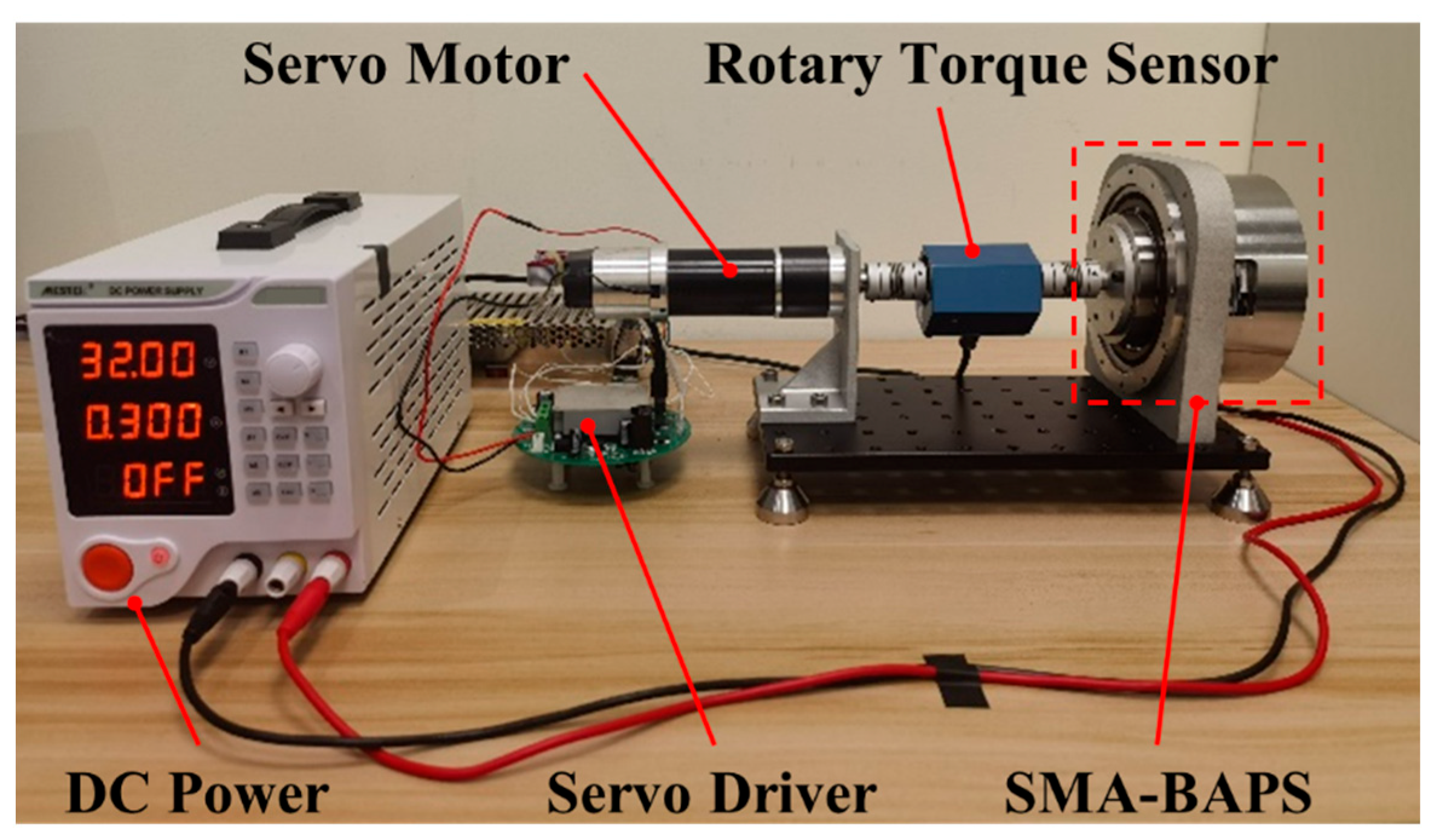
Joule heating is commonly used to heat the SMA above the transformation start temperature As and induce the reverse martensite transformation. Due to energy conservation, the Joule heat converts into three parts: the internal energy of the SMA and PTFE capillary tube, the latent heat, and the convective heat loss. To determine the electrical parameters (applied current and heating time), the energy conservation model is established for the SMA wire actuator, which is represented by [25,26] the following:
I 2 R Δ t = m 1 c p 1 ( T max T 0 ) + m 2 c p 2 ( T max T 0 ) + m 1 λ + h A sf ( T max T 0 ) Δ t
The calculation parameters of the above equation are listed in Table 4. The maximum heating temperature Tmax is assumed as 140 °C, which implies that the martensite transformation is complete. Figure 16 demonstrates the curve of the applied current I and heating time Δt. To acquire an actuation response of less than 5 s, the applied current and heating time are designed as 5 A and 3 s, respectively.

4. Prototype Tests

According to the design scheme stated above, the prototype of the SMA-BAPS was fabricated and assembled. The overall dimension of the prototype was Φ132 × 72 mm. The total mass was 2.5 kg, while the mass of the actuated part for preload adjustment, which was composed of the screw pair, the SMA wire actuator, and the needle roller thrust bearing, was 0.5 kg. To evaluate the performance of preload adjustment, two prototype tests were conducted. The preload level was featured by two parameters of the spindle: the resistive torque under stable running as well as the natural frequency of spindle axial mode.

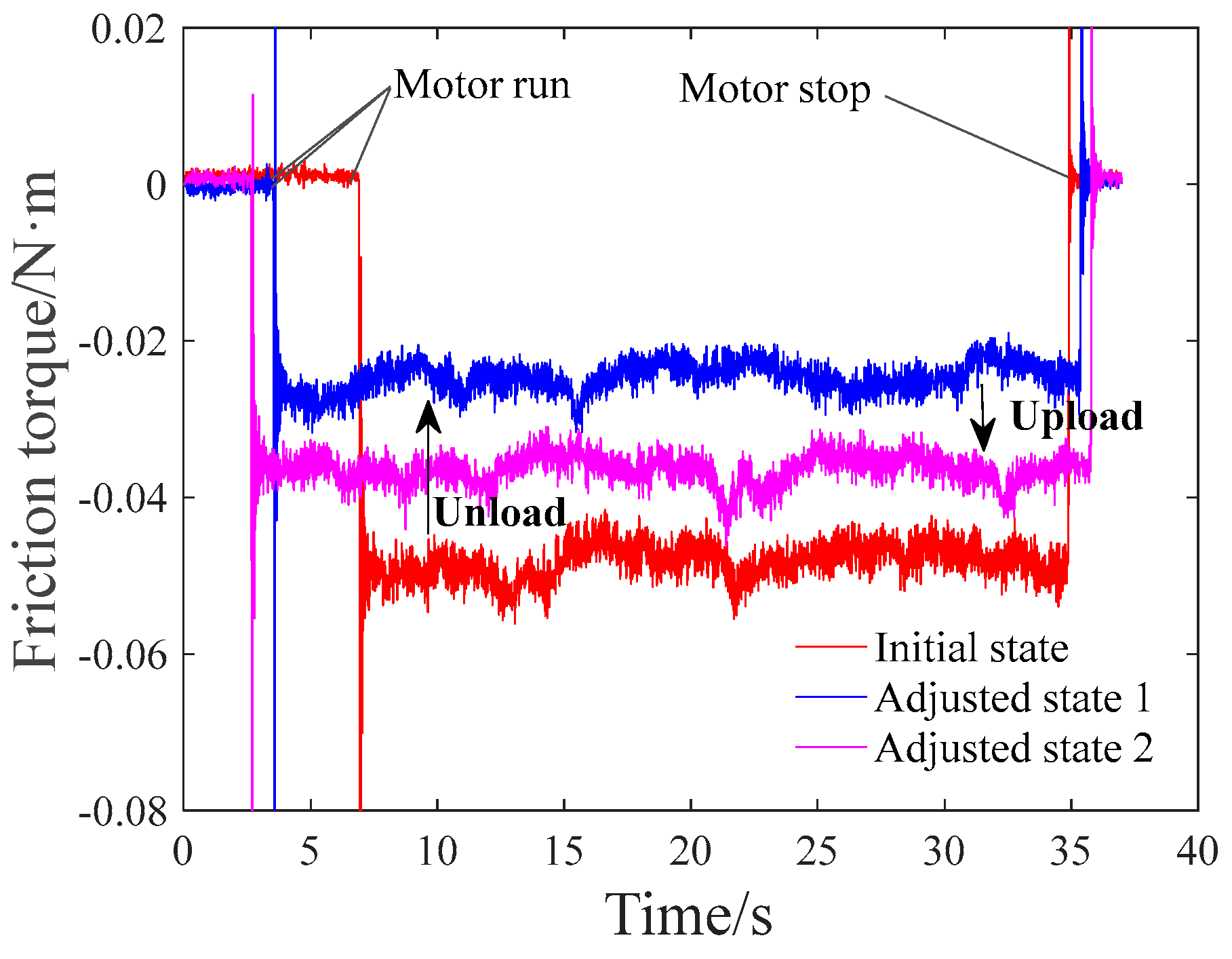
4.1. Resistive Torque Test

As the bearing is running at a low speed and there is only axial preload on the spindle, the relationship between the bearing preload F2 and the resistive torque Mf is described by [1] the following:
M f = f c d m F 2
where fc and dm are constant parameters of the bearing. Equation (15) implies that the resistive torque is proportional to the bearing preload. As a result, the resistive torque test was conducted to evaluate the preload level of the spindle before and after preload adjustment.
The experimental bench for the resistive torque test is shown in Figure 17. A DC servo motor was employed to drive the spindle, while a rotary torque sensor recorded the resistive torque under stable running. The rotating speed of the motor was set to 12.5 rpm through a servo driver. Moreover, DC power was used to apply current on the SMA wire and thus adjust the bearing preload. With the proposed SMA-BAPS, the resistive torque of the spindle under a variable bearing preload was recorded and analyzed. Three groups of experiments were conducted, which were the single uploading configuration, the single unloading configuration, and the antagonistic configuration. For the antagonistic configuration, the BAPS was preloaded to a high load level initially. Then, the unloading SMA wire was actuated to unload the bearing preload. Afterwards, the uploading SMA wire was electrically heated, which caused the increase in the bearing preload.
The results of the resistive torque test for single actuation are demonstrated In Figure 18. Under the uploading condition, the mean resistive torque varied from 0.027 to 0.037 N·m. According to Equation (15), this implied a 37% increase in the bearing preload. Moreover, the mean resistive torque varied from 0.047 to 0.025 N·m under the unloading condition, which was equivalent to a 46.8% decrease in the bearing preload. Obviously, the adjusted range of the bearing preload under the unloading configuration was higher than the uploading range. This could be explained by the loading path of the SMA wire actuator, as shown in Figure 19. The resistive friction increased as the SMA was actuated under the uploading case, while the resistive force decreased under the unloading case. During the uploading configuration, the maximum actuation force of the SMA was restricted by the load–displacement curve of the Austenite phase. As the displacement of the SMA wire was recovered, the maximum actuation force was reduced, implying the descent in the actuation capacity for the SMA.
The recorded results of resistive torque for bidirectional actuation are shown in Figure 20. With the proposed SMA-BAPS, it was validated that the resistive torque was successively adjusted to a low-preload state and a high-preload state. As the unloading SMA worked, the resistive torque of the spindle dropped from 0.045 N·m to 0.026 N·m. Then, due to the controlled actuation of the uploading SMA, the resistive torque increased from 0.026 N·m to 0.037 N·m. Similarly to the results of the single configuration, the variation range of the uploading case was lower than that of the unloading case.

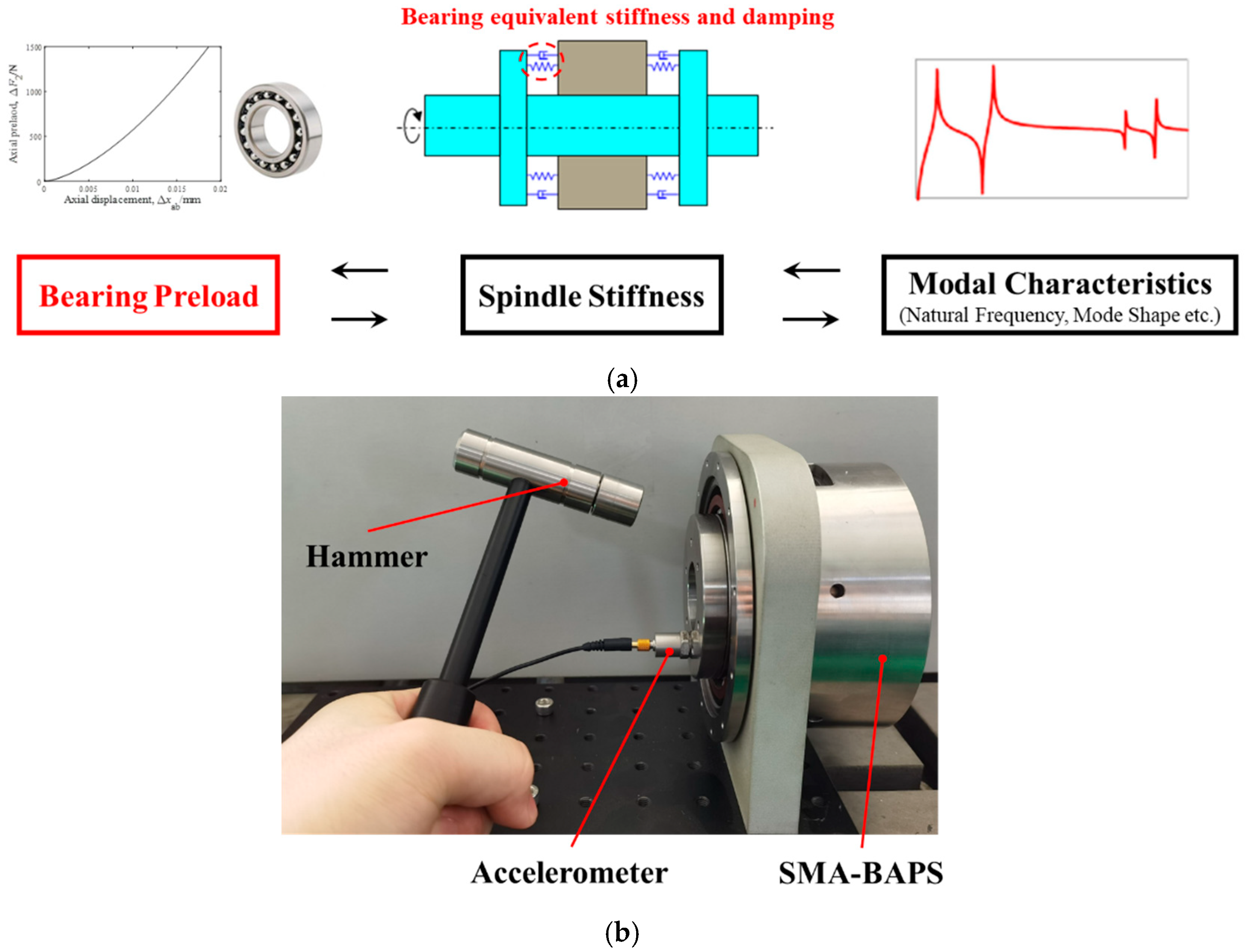
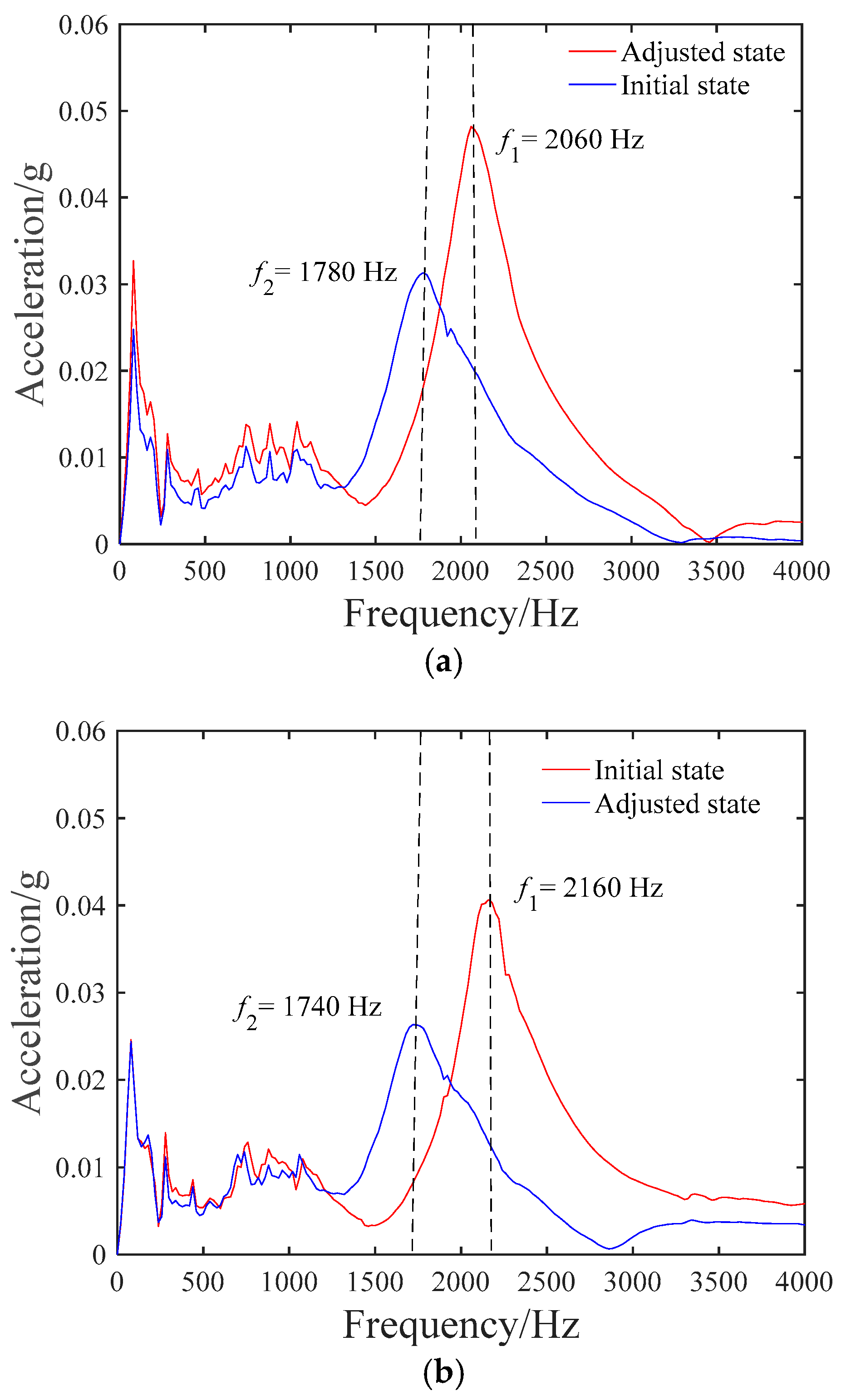
4.2. Modal Impact Test

As illustrated in Figure 6, a basic characteristic of ball bearing is that the axial stiffness increases with the bearing preload, which could be explained through the Hertz theory (Equations (6)–(9) in Section 3.1). Moreover, this implies that the axial stiffness of the spindle determines the modal parameters of the mechanical system, as shown in Figure 21a. Numerous experimental works have indicated that the preload level significantly affects the dynamic characteristics of the spindle [14,27,28]. As a result, a modal impact test was developed in this study to further validate the performance of the preload adjustment.
The test instrument is described in Figure 21b. The housing of the BAPS was fixed on the ground, while an impulse hammer was employed to apply the impact in the axial direction of the spindle. Simultaneously, a uniaxial accelerometer was attached on the flange end of the spindle, which measured the axial acceleration magnitude of the shaft. The modal test was conducted under the uploading configuration and the unloading configuration. For each configuration of preload adjustment, the accelerated response magnitude of the initial state and the adjusted state were both recorded and processed.
The acceleration magnitude spectra of the modal impact test are illustrated in Figure 22. The low-amplitude peak occurring below 1500 Hz corresponded to the casing mode that was beyond the interest of this paper. Through the uploading configuration of the SMA-BAPS, the preload-dependent mode of the axial motion occurred at 1780 Hz and 2060 Hz. It was indicated that the natural frequency of the spindle increased after the uploading configuration, which implied the rise in the axial stiffness and the bearing preload. Reversely, the natural frequency of the spindle decreased from 2160 Hz to 1740 Hz during the unloading configuration. This represented that the variation range of the bearing preload for the uploading configuration was lower than that of the uploading configuration, which has been demonstrated in the resistive torque test. Moreover, the accelerated magnitude under natural frequency increased with the bearing preload, which coincided with the load-independent damping model of Gunduz’s investigation [28].

4.3. Discussion

Prototype tests of the SMA-BAPS have shown that this mechanism was capable of inducing both the uploading and unloading of the bearing preload. According to the actual situation, two experimental methods for preload evaluation could be employed. The resistive torque test could be easily conducted on the single spindle while the modal test was suitable for the overall structure. However, the two experiments conducted cannot reflect the preload level accurately. The calibration was needed to link the preload with the testing parameters (restive torque and natural frequency, etc.). Moreover, the uploading amplitude was nearly half of the unloading amplitude, which was determined by the maximum actuation force of the SMA wire. In other words, uploading bearing the preload using the SMA wire was harder than the unloading process of releasing the strain energy of the bearing. Consequently, for the uploading configuration, a larger radius of the SMA wire was needed to acquire the same adjustment range of the bearing preload as in the unloading case. The potential applications of the proposed SMA-BAPS are aerospace mechanisms and advanced motors, where size and reliability are major concerns. However, the proposed prototype only fulfilled the bidirectional switch of two preload states. As for future work, extended modeling and experiments are being prepared to achieve the multiple preload states. One key point is the control strategy of the antagonistic SMA actuators considering the friction of the screw pair.

5. Conclusions

Based on the SMA actuator and the screw pair, a novel SMA-actuated bearing active preload system (SMA-BAPS) was introduced and experimentally demonstrated. Due to the self-locking characteristic of the screw pair, the proposed BAPS was able to maintain the high preload as it was assembled. Then preload adjustment could be performed through the actuation of the SMA wire actuator. Based on the lumped model of the SMA-BAPS, the axial length variation in the screw pair was fully undertaken via the deformation of the paired bearings. The detailed design flow to determine the lead of the screw pair as well as the SMA parameters was also presented. According to the test results, the established BAPS induced a 47% reduction and a 37% rise in the resistive torque, with a response time of less than 5 s. Moreover, the natural frequency of the spindle varied obviously throughout the uploading and unloading configurations of the SMA-BAPS. Compared with the unloading configuration, it was found that the uploading configuration showed a lower range of preload adjustment. Consequently, a larger radius of the SMA wire was needed to acquire the same adjustment range of the bearing preload. Further research will mainly focus on the control of the antagonistic SMA actuators to achieve multiple preload adjustments.

Author Contributions

Conceptualization, Y.Z. (Yuhang Zhang); Methodology, X.Z.; Validation, X.Z.; Formal analysis, J.J.; Investigation, J.J.; Resources, Q.Z., Y.Z. (Yuanzi Zhou) and R.S.; Writing—original draft, Y.Z. (Yuhang Zhang). All authors have read and agreed to the published version of the manuscript.

Funding

This work was supported by the Foundation of National Key Laboratory of Space Intelligent Control (Grant No. 2023-JCJQ-LB-006-01), National Natural Science Foundation of China (Grant No. 52105048 and No. 52272357), and Young Elite Scientists Sponsorship Program by CAST (Grant No. YESS20200183).

Data Availability Statement

The data that support the findings of this study are available from the corresponding author upon reasonable request.

Conflicts of Interest

The authors declare that they have no known competing financial interests or personal relationships that could have appeared to influence the work reported in this paper.

References

  1. Harris, T.A.; Kotzalas, M.N. Advanced Concepts of Bearing Technology: Rolling Bearing Analysis, 5th ed.; Taylor & Francis: Boca Raton, FL, USA, 2006. [Google Scholar]
  2. Roberts, E.W. Space Tribology Handbook, 4th ed.; ESR Technology: Warrington, UK, 2007. [Google Scholar]
  3. Hwang, Y.-K.; Lee, C.-M. A review on the preload technology of the rolling bearing for the spindle of machine tools. Int. J. Precis. Eng. Manuf. 2010, 11, 491–498. [Google Scholar] [CrossRef]
  4. Lee, C.; Woo, W.; Kim, D. The latest preload technology of machine tool spindles: A review. Int. J. Precis. Eng. Manuf. 2017, 18, 1669–1679. [Google Scholar] [CrossRef]
  5. Li, T.; Kolar, P.; Li, X.; Wu, J. Research development of preload technology on angular contact ball bearing of high speed spindle: A review. Int. J. Precis. Eng. Manuf. 2020, 21, 1163–1185. [Google Scholar] [CrossRef]
  6. Lewis, S.D.; Humphries, M.E. An introduction to bearing active preload systems—Technology and performance benefits. In Proceedings of the 11th European Space Mechanisms and Tribology Symposium, Lucerne, Switzerland, 21–23 September 2005. [Google Scholar]
  7. Jiang, S.; Mao, H. Investigation of variable optimum preload for a machine tool spindle. Int. J. Mach. Tools Manuf. 2010, 50, 19–28. [Google Scholar] [CrossRef]
  8. Zhang, Y.; Li, X.; Hong, J.; Wang, S.; Li, B.; Sun, Y.; Zheng, S. Rotation Accuracy Analysis of Spindle Under Variable Preload. In Proceedings of the ASME 2017 International Mechanical Engineering Congress and Exposition, Volume 4A: Dynamics, Vibration, and Control, Tampa, FL, USA, 3–9 November 2017. [Google Scholar]
  9. Zverv, I.; Pyoun, Y.; Lee, K.; Kim, J.; Jo, I.; Combs, A. An elastic deformation model of high speed spindles built into ball bearings. J. Mater. Process. Technol. 2005, 170, 570–578. [Google Scholar] [CrossRef]
  10. Hwang, Y.; Lee, C. Development of a newly structured variable preload control device for a spindle rolling bearing by using an electromagnet. Int. J. Mach. Tools Manuf. 2010, 50, 253–259. [Google Scholar] [CrossRef]
  11. Hwang, Y.; Park, I.; Paik, K.; Lee, C. Development of a variable preload spindle by using an electromagnetic actuator. Int. J. Precis. Eng. Manuf. 2014, 15, 201–207. [Google Scholar] [CrossRef]
  12. Tsutsui, S.; Aoyama, T.; Inasaki, I. Development of a spindle system with an adjustable preload mechanism using a piezoelectric actuator. JSME Int. J. 1988, 31, 593–597. [Google Scholar] [CrossRef]
  13. Chen, J.; Chen, K. Bearing load analysis and control of a motorized high speed spindle. Int. J. Mach. Tools Manuf. 2005, 45, 1487–1493. [Google Scholar] [CrossRef]
  14. Hu, G.; Zhang, D.; Gao, W.; Chen, Y.; Liu, T.; Tian, Y. Study on variable pressure/position preload spindle-bearing system by using piezoelectric actuators under close-loop control. Int. J. Mach. Tools Manuf. 2018, 125, 68–88. [Google Scholar] [CrossRef]
  15. Hwang, Y.; Lee, C. Development of automatic variable preload device for spindle bearing by using centrifugal force. Int. J. Mach. Tools Manuf. 2009, 49, 781–787. [Google Scholar] [CrossRef]
  16. Razban, M.; Movahhedy, M.R. A speed-dependent variable preload system for high speed spindles. Precis. Eng. 2015, 40, 182–188. [Google Scholar] [CrossRef]
  17. Lewis, S.D.; Humphries, M.E. Development, pre-qualification and application of an active bearing preload system. In Proceedings of the 38th Aerospace Mechanisms Symposium, Williamsburg, VA, USA, 17–19 May 2006. [Google Scholar]
  18. Lewis, S.D.; Munro, G.; Humphries, M.E.; Székely, G. Development of an adjustable bearing preload enabled-optical terminal. In Proceedings of the 13th European Space Mechanisms and Tribology Symposium, Vienna, Austria, 23–25 September 2009. [Google Scholar]
  19. Florian, S.; Yann, M.; Thomas, A.; Jean-Bernard, M. Discharge component for pair of bearings using shape memory actuators. In Proceedings of the 18th European Space Mechanisms and Tribology Symposium, Munich, Germany, 18–20 September 2019. [Google Scholar]
  20. Thomas, A.; Yann, M.; Florian, S. Unloading mechanism using shape memory alloy actuators for ball bearings—Space qualification tests sequence. In Proceedings of the 2019 PEGASUS Student Conference, Glasgow, UK, 10–12 April 2019. [Google Scholar]
  21. Videira, E.; Lebreton, C.; Lewis, S.D.; Gaillard, L. Design, assembly and preloading of ball bearings for space applications—Lessons learned and guidelines for future success. In Proceedings of the 15th European Space Mechanisms and Tribology Symposium, Noordwijk, The Netherlands, 25–27 September 2013. [Google Scholar]
  22. El-Latlf, A.K.A.; Ziada, H.H. Stiffness of bolted joints. J. Eng. Appl. Sci. 1981, 1, 17–27. [Google Scholar]
  23. Wileman, J.; Choudhury, M.; Green, I. Computation of member stiffness in bolted connections. Trans. ASME 1991, 113, 432–437. [Google Scholar] [CrossRef]
  24. Zhang, D.; Gao, S.; Xu, X. A new computational method for threaded connection stiffness. Adv. Mech. Eng. 2016, 8, 1–9. [Google Scholar] [CrossRef]
  25. Meier, H.; Oelschlaeger, L. Numerical thermomechanical modelling of shape memory alloy wires. Mater. Sci. Eng. A 2004, 378, 484–489. [Google Scholar] [CrossRef]
  26. Jani, J.M.; Huang, S.; Leary, M.; Subic, A. Numerical modeling of shape memory alloy linear actuator. Comput. Mech. 2015, 56, 443–461. [Google Scholar] [CrossRef]
  27. Gunduz, A.; Dreyer, J.T.; Singh, R. Effects of preloads on vibration transmission through double row angular contact ball bearings. In Proceedings of the ASME 2011 International Design Engineering Technical Conferences & Computers and Information in Engineering Conference, Washington, DC, USA, 28–31 August 2011. [Google Scholar]
  28. Gunduz, A.; Dreyer, J.T.; Singh, R. Effect of bearing preloads on the modal characteristics of a shaft-bearing assembly: Experiments on double row angular contact ball bearings. Mech. Syst. Signal Process. 2012, 31, 176–195. [Google Scholar] [CrossRef]
Figure 1. Schematic diagram of the SMA-BAPS.
Aerospace 12 00637 g001
Figure 2. SMA wire actuator enclosed by PTFE tube.
Aerospace 12 00637 g002
Figure 3. Design flow of the SMA-BAPS.
Aerospace 12 00637 g003
Figure 4. Analytical model of the SMA-BAPS ((a) before preload adjustment, (b) after preload adjustment).
Aerospace 12 00637 g004
Figure 5. The relationship between Kab and Knb.
Aerospace 12 00637 g005
Figure 6. Mechanism of bearing preload adjustment with the proposed screw pair.
Aerospace 12 00637 g006
Figure 7. Self-locking state of the screw pair under axial preload (φ = atan[s/(πDr)]—the rising angle, ρ = atanμ—the equivalent friction angle, F2—bearing preload, Ff—friction force on the helicoidal surface, and Fn—normal force on the helicoidal surface).
Aerospace 12 00637 g007
Figure 8. Processed screw pair with the lead of 3 mm.
Aerospace 12 00637 g008
Figure 9. Uploading model of the screw pair.
Aerospace 12 00637 g009
Figure 10. Unloading model of the screw pair.
Aerospace 12 00637 g010
Figure 11. Test of the processed screw pair ((a) test bench, (b) test result).
Aerospace 12 00637 g011
Figure 12. Simplified model of the SMA wire actuator.
Aerospace 12 00637 g012
Figure 13. Stress–strain actuation path of single arranged SMA actuator with fixed length L = 100 mm ((a) uploading, (b) unloading).
Aerospace 12 00637 g013
Figure 14. Stress–strain actuation path of single arranged SMA actuator with fixed radius r = 0.25 mm ((a) uploading, (b) unloading).
Aerospace 12 00637 g014
Figure 15. Stress–strain actuation path of antagonistic arranged SMA actuator with fixed length L = 100 mm ((a) uploading, (b) unloading).
Aerospace 12 00637 g015
Figure 16. Relationship between applied current and heating time when Tmax is 140 °C.
Aerospace 12 00637 g016
Figure 17. Test bench for resistive torque measurement.
Aerospace 12 00637 g017
Figure 18. Results of resistive torque test ((a) uploading, (b) unloading).
Aerospace 12 00637 g018
Figure 19. Loading path of SMA wire actuator under uploading and unloading configuation.
Aerospace 12 00637 g019
Figure 20. Results of resistive torque test.
Aerospace 12 00637 g020
Figure 21. Schimtic of modal impact test ((a) test principle, (b) experimental setup).
Aerospace 12 00637 g021
Figure 22. Results of modal test ((a) uploading, (b) unloading).
Aerospace 12 00637 g022
Table 1. Parameters of the angular contact ball bearing (7212ACTA).
d1 (mm)D1 (mm)α0 (°)fifoDw1 (mm)Z1
Inner diameterOuter diameterInitial contact angleInner groove curvatureOuter groove curvatureDiameter of ballNumber of balls
60110250.5250.53514.2815
Table 2. Parameters of the needle roller thrust bearing (AXK85110).
d2 (mm)D2 (mm)l (mm)Dw2 (mm)Z2
Inner diameterOuter diameterLength of the contact lineDiameter of needleNumber of needles
851109.2446
Table 3. Parameters of the actuation path calculation.
ParametersValues
s (mm)3
μ0.15
Dr (mm)106
EM (GPa)30
EA (GPa)70
εL0.04
σs (MPa)100
σf (MPa)170
Table 4. Parameters of the energy conservation model for SMA wire actuator.
ParametersValues
R (Ω)0.6
cp1 (J·(kg °C)−1)836.8
cp2 (J·(kg °C)−1)1030
m1 (kg)1.6 × 10⁻⁴
m2 (kg)7.4 × 10⁻⁵
Tmax (°C)140
T0 (°C)25
λ (J·kg−1)24,184
h (J·(m2·°C·s)−1)39.2
Disclaimer/Publisher’s Note: The statements, opinions and data contained in all publications are solely those of the individual author(s) and contributor(s) and not of MDPI and/or the editor(s). MDPI and/or the editor(s) disclaim responsibility for any injury to people or property resulting from any ideas, methods, instructions or products referred to in the content.

