Article

Analysis of Vibration Characteristics of Angular Contact Ball Bearings in Aviation Engines Under Changing Conditions

by
Yanfang Dong
1,2,3,*,
Zibo Yan
1,
Jianyong Sun
4,
Wei Yu
1,
Hai Zhang
3,
Wenbo Zhou
1 and
Jihao Jin
1
1
School of Mechatronics Engineering, Henan University of Science and Technology, Luoyang 471003, China
2
Collaborative Innovation Center of Machinery Equipment Advanced Manufacturing of Henan Province, Luoyang 471003, China
3
Suzhou Bearing Factory Co., Ltd., Suzhou 215000, China
4
Luoyang Bearing Research Institute Co., Ltd., Luoyang 471039, China
*
Author to whom correspondence should be addressed.
Aerospace 2025, 12(7), 623; https://doi.org/10.3390/aerospace12070623
Submission received: 11 June 2025 / Revised: 4 July 2025 / Accepted: 9 July 2025 / Published: 11 July 2025

Abstract

This paper addresses the vibration characteristics of angular contact ball bearings in aircraft engines under variable load conditions. Based on multibody dynamics theory, a dynamic model of the bearing was established. Vibration data under actual operating conditions were obtained using an experimental test platform. This study systematically investigated the influence of rotational speed, axial load, and radial load on the vibration acceleration level of the bearing outer ring. Through a comparison of simulation and experimental data (with an error rate below 10%), the reliability of the model was validated. The results indicate that the bearing vibration acceleration level exhibits a nonlinear increasing relationship with rotational speed. An increase in radial load significantly amplifies the amplitude of acceleration-level fluctuations, while appropriately increasing axial load can reduce bearing vibration intensity. Under variable load coupling conditions, the dynamic interaction between axial and radial forces results in complex nonlinear vibration responses, with a 2 s acceleration time achieving the optimal balance between vibration suppression and efficiency (steady-state average of 70.4 dB). Additionally, the morphological characteristics of the cage center-of-gravity trajectory (such as trajectory disorder and poor smoothness) are closely related to vibration characteristics, revealing the critical role of dynamic load changes in bearing stability. The research results provide a theoretical basis for optimizing the operating conditions, vibration control, and reliability design of aircraft engine bearings.

1. Introduction

Aviation engines serve as the core power units of modern aircraft, and their reliability directly impacts flight safety and operational efficiency. Within the complex rotor systems of engines, angular contact ball bearings play a critical role in supporting the rotor, transmitting loads, and ensuring motion precision. Statistics indicate that approximately 30% of mechanical failures in aviation engines are directly related to the bearing system. And traditional vibration analysis methods based on steady-state assumptions are no longer sufficient to meet the fault warning and health management requirements of modern aviation engines [1,2,3].
The vibration characteristics of angular contact ball bearings essentially stem from their complex multi-physics field coupling mechanisms. Lourari A et al. [4] developed a new method based on CEEMDAN (Complete Ensemble Empirical Mode Decomposition with Adaptive Noise) vibration signal decomposition and SBS (Sequential Backward Selection) feature selection, enabling high-precision classification of bearing fault states, which is suitable for bearing vibration fault-state monitoring in industrial applications. Yu A et al. [5] found that under variable load conditions, load sequence and interactions significantly affect the vibration fatigue life of rolling bearings, and an improved nonlinear damage model provides more accurate life assessment. Pang X et al. [6] found that a rigid–flexible coupled model significantly reduces bearing vibration (reducing rotational error by 67–76% and stabilizing acceleration) compared to a purely rigid model, and reducing the friction coefficient can decrease roller force by 50–76%, providing a basis for vibration reduction design in wind turbine bearings. Hamadache M et al. [7] proposed a fault diagnosis method based on rotor speed signals (RSB-BFD) as an alternative to vibration monitoring, which precisely identifies bearing faults through an improved PCA (Principal Component Analysis) algorithm, offering the advantages of low cost and high applicability. Wang X B et al. [8] addressed the limitation of vibration monitoring in hub motor bearings by innovatively proposing an electrical signal decoupling diagnosis method—by combining stator current load demodulation normalization with order tracking–STFT (Short-Time Fourier Transform) time–frequency analysis and adaptive CNN (Convolutional Neural Network) classification—achieving high-precision detection of inner- and outer-ring wear under variable load conditions, with accuracy surpassing traditional vibration-based methods. Han Q et al. [9] found that local slippage in cylindrical roller bearings exhibits periodic changes, and increases in radial load, bending moment, or time-varying load amplitude all suppress roller slippage speed; the sliding frequency under time-varying loads is a combination of the inner-ring frequency and track speed, revealing nonlinear vibration mechanisms. Yu A et al. [5] found that variable load sequences and their interactions significantly affect the vibration fatigue life of rolling bearings. An improved nonlinear damage model validated across six materials can more accurately predict damage accumulation and life, providing a basis for bearing condition monitoring.
In addition, Zhao W et al. [10] proposed a bearing vibration diagnosis method based on compressed sensing and a multi-scale CNN. They used semi-tensor product compressed sensing to solve the bottleneck of vibration data storage and transmission, and utilized a multi-scale inverted residual CNN to accurately extract variable load fault features, achieving high-precision identification of bearing faults across different operating conditions. Moshrefzadeh A et al. [11] addressed the issue of confusion in bearing vibration features under variable operating conditions by innovatively adopted spectral amplitude modulation (SAM) to extract load-invariant features, based on envelope spectrum pulse quantization cyclostationarity, combined with SVM/kNN (Support Vector Machine/k-Nearest Neighbors) to achieve cross-condition diagnosis; three test benches validated the high detection rate for local and distributed defects. Fang B et al. [12] proposed a new method for modeling the stiffness matrix of ball bearings, revealing the influence of speed/load/structural parameters on stiffness, with stiffness changes directly correlated with the vibration characteristics of the bearing–rotor system, providing a critical basis for vibration reduction design. Fan H et al. [13] proposed a bearing diagnostic method based on vibration signal grayscale images and CNN–adaptive batch normalization. Average accuracies of 98.7% across 13 variable load operating conditions and 99.0% under unknown conditions were achieved. Tu W et al. [14] found that the cage of cylindrical roller bearings is prone to unstable vibration under variable speed conditions, particularly during the initial acceleration phase and final deceleration phase. Appropriately increasing angular acceleration can enhance stability, but excessive fluctuations exacerbate vibration, with the outer-ring guiding force being the key vibration suppression factor. Wang B et al. [15] found that the vibration stability of double-row tapered roller bearings in high-speed trains under variable speed conditions is influenced by the coupling of fault location and acceleration—inner-ring faults pose greater risks at low accelerations, while outer-ring faults dominate at high accelerations. And in actual operation, inner-ring faults require greater attention.
Extreme operating conditions can cause bearing vibration characteristics to exhibit significant nonlinear and transient features. Under variable load conditions, the nonlinear vibration system of bearings (including Hertzian contact deformation, cage clearance, and time-varying oil film stiffness) triggers complex dynamic responses when there are sudden changes in speed, load, or temperature. Sudden changes in rolling-element spin can excite subharmonic resonance, while lubrication transients cause friction excitation steps. Traditional steady-state models simplify such coupling effects, resulting in vibration peak prediction errors exceeding 40% [16,17,18,19]. Therefore, establishing a variable-operating-condition dynamic model to reveal the multi-parameter coupled vibration mechanism has become a key challenge in enhancing aviation engine safety.
This article explores the subject through four sections: bearing dynamic modeling, experimental testing, variable-operating-condition vibration characteristic analysis, and model validation. It focuses on the mechanisms by which rotational speed and load influence vibration acceleration levels and proposes an analysis of the correlation between the center-of-mass trajectory of the cage and vibration characteristics.

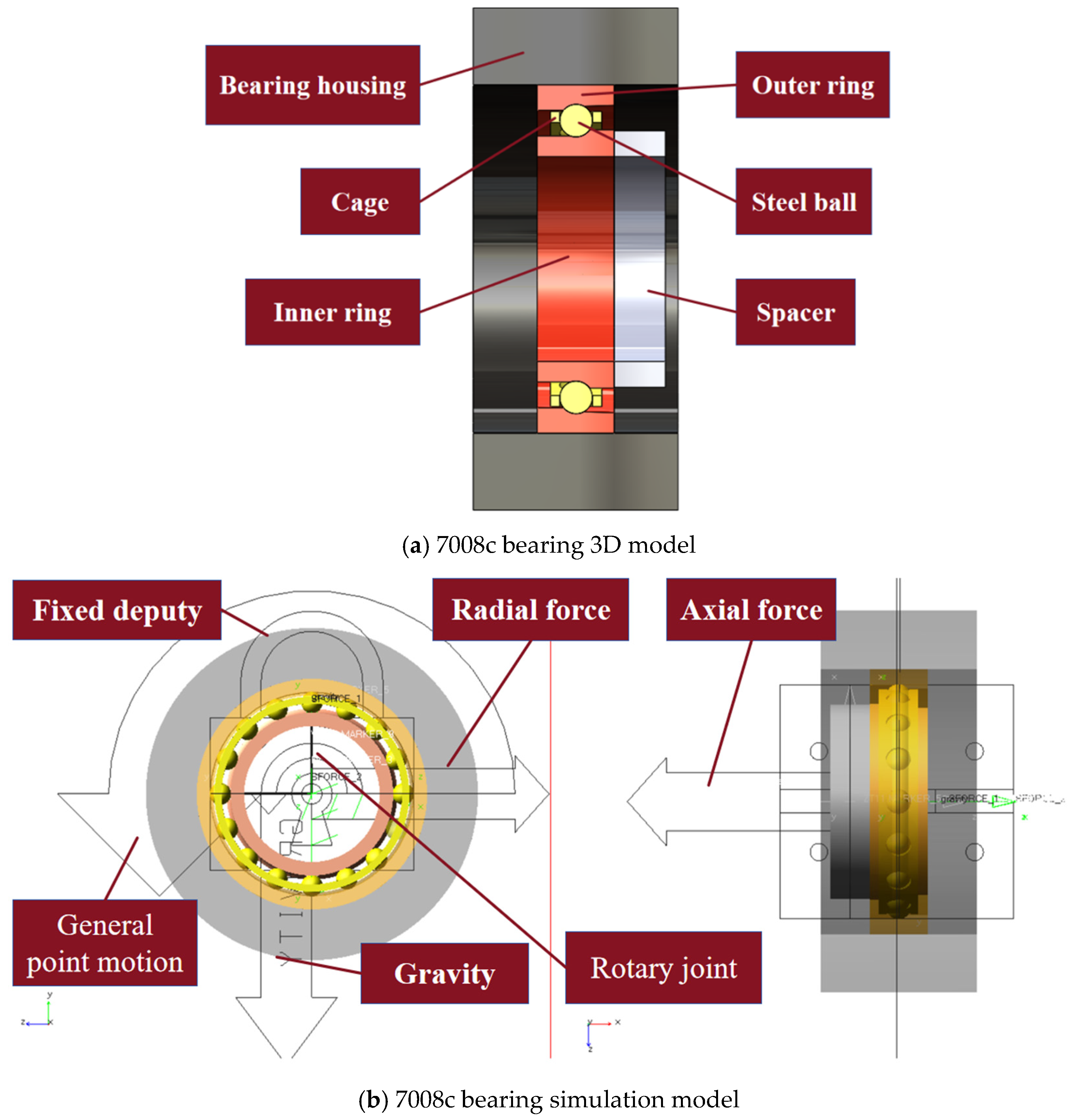
2. Simulation Model Construction

To perform dynamic simulation calculations for the 7008C bearing [20], the first step is to convert the established 3D model of the 7008C bearing into a parasolid file and import it into ADAMS 2019.0228 simulation software. In the global coordinate system, constraints are set for the model: the bearing housing is set as a fixed joint to provide stable support, and the outer ring of the bearing is restricted via the General point motion command to limit its rotational and translational degrees of freedom around the axial axis. The remaining degrees of freedom are unrestricted to allow vibration under load. The inner ring is set as a rotating joint to simulate its rotational motion, and the cage is set as a planar joint to restrict its movement to the YOZ plane. To track the dynamic behavior of the cage, a center-of-mass trajectory monitoring module is added to the model, which uses ADAMS/PostProcessor to record its motion trajectory parameters in real time. Additionally, rigid–rigid collision contacts are set between the rollers and the inner ring, outer ring, and cage to simulate the contact relationship between the rolling elements and the inner and outer rings. Rigid–rigid collision contacts are also set between the outer ring and the bearing housing, and between the inner ring and the shaft sleeve. Regarding load application, axial loads are applied to the wide flange of the outer ring, while radial loads are applied to the inner ring. The inner ring of the bearing is adjacent to the installation spacer, which is set as a fixed pair to provide axial positioning.
In ADAMS, for constant load conditions, loads can be applied by directly assigning fixed values through the force property dialogue box. For variable load conditions, where loads and rotational speed exhibit nonlinear changes over time, a step function can be used to establish the mapping relationship between loads and time. Through the above settings, the model accurately reflects the actual operating state of the bearing, thereby obtaining vibration data for the outer ring. The 3D and simulation models of the 7008C bearing are shown in Figure 1.
Based on Hertz contact theory, contact collisions can be equivalently modeled as a nonlinear spring–damper system, with contact forces estimated using the impact function method. The impact function method uses the impact function to calculate the collision force, which consists of two components: elastic force and damping force. This method is of significant importance in the dynamics of mechanical systems, particularly in the design of rolling bearings, such as the 7008C bearing, where it can optimize the distribution of contact forces, enhance load-carrying capacity, and extend service life. Through a combination of Hertz’s theory with the impact function method, the contact characteristics of bearings under different operating conditions can be analyzed more accurately, providing a theoretical basis for performance optimization.
F i m p a c t = 0 , q > q 0 k ( q q 0 ) e c m a x ( d q / d t ) t e p ( q , q 0 d , ) , x 0
where q0 is the initial distance between the two colliding objects; q is the actual distance between the two objects during the collision process; dq/dt is the rate of change in the distance between the two objects over time, i.e., the collision velocity; k is the stiffness coefficient; e is the collision exponent, with point contact set to 1.5; cmax is the maximum damping coefficient N/(mm·s−1), typically taken as 0.1% to 1% of the equivalent stiffness; and d is the penetration depth, with d = 0.1, which determines when the damping force reaches its maximum. To prevent discontinuities in the damping force during the collision process, a step function is introduced, specifically step (x, x0, h0, x1, h1).
In ball bearings, the contact between the ring and the ball is point contact, and the contact stiffness coefficient is calculated using the following formula:
K = π k ¯ e E R m 4.5 n 3
In the formula, E represents the equivalent total modulus, E represents the elastic modulus of the rolling element, K ¯ e represents the contact ellipticity, and m and n represent the first-class elliptic curve integral and second-class elliptic curve integral, respectively.
The Coulomb model is used to calculate the friction between the contact elements. The specific expression for the friction coefficient is
μ v = s i g n ( v ) μ d ; | v | > μ d s t e p ( | v | , v d , μ d , v s , μ s ) s i g n ( v ) ; v s | v | μ d s t e p ( v , v s , μ s , v s , μ s ) ; v s < v < v s
In the expression, sign is a symbolic function that determines the positive or negative value of the coefficient of kinetic friction; vs is the relative sliding velocity between the two contacting objects; ud is the coefficient of kinetic friction between the two objects; vd is the kinetic sliding velocity; and us is the coefficient of static friction between the two objects, which is the static sliding velocity.
All parameters and equations above are based on reference [21]. Considering the convergence speed and accuracy of the simulation model, the GSTIFF variable step-size integration algorithm is used for solution.

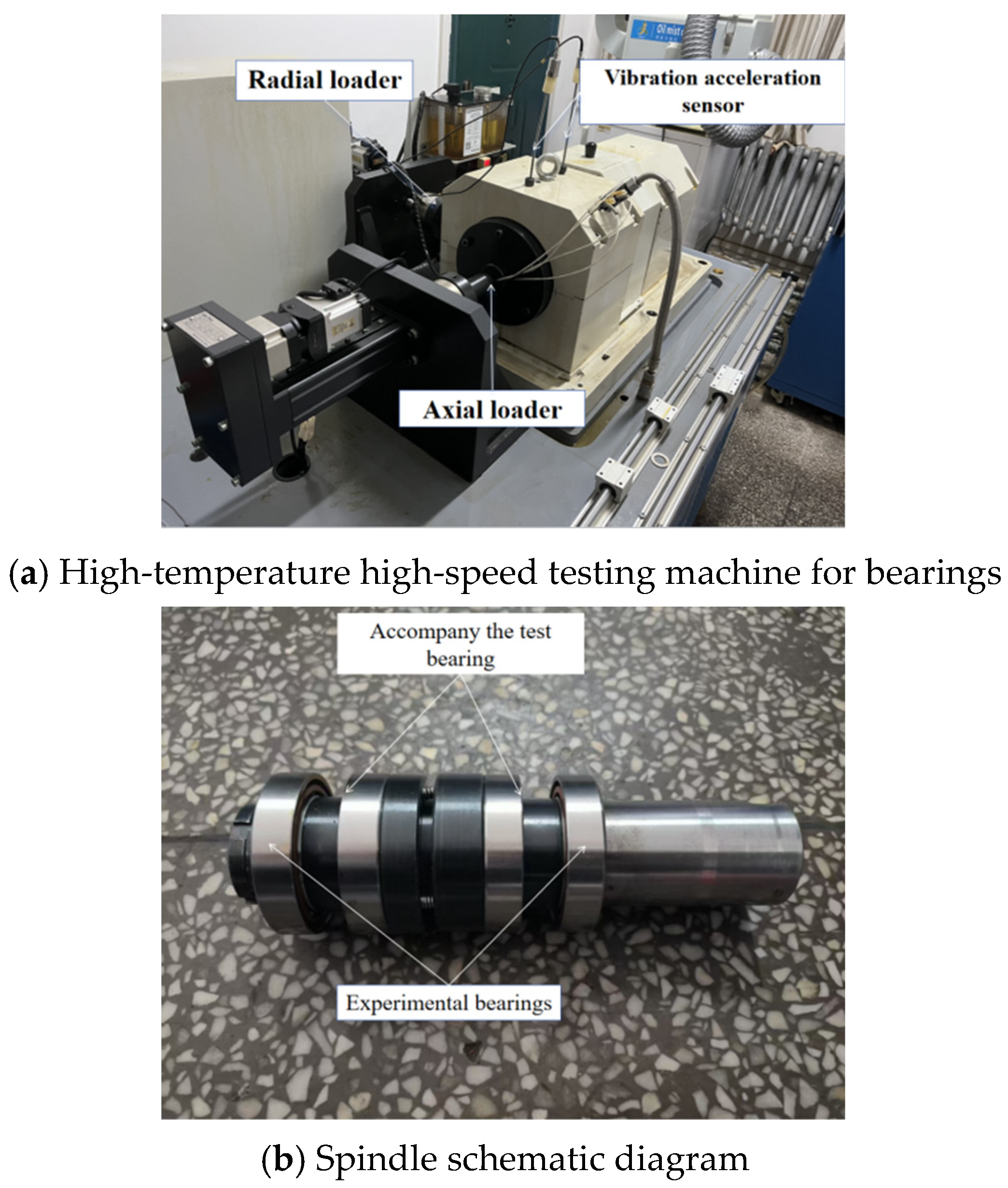
3. Testing Equipment and Testing Systems

This paper is based on the SYJ-GWGS20-60 high-temperature, high-speed bearing life testing machine for bearing vibration testing. The testing machine mainly consists of a main shaft system, a base, and axial and radial loading mechanisms. The main shaft system of the testing machine adopts a horizontal structure, which is convenient for disassembling and assembling bearings. The drive system is controlled by an electric spindle, which can achieve stepless speed regulation. The test bearings selected are the 7008C/P4 angular contact ball bearings from the Bearing Research Institute, with a recommended axial preload of 65–300 N. Under conditions of constant speed, constant load, proper installation, and adequate lubrication, these bearings can simultaneously withstand high axial and radial loads. The main body and spindle system of the test machine are shown in Figure 2.
The specific technical parameters of the SYJ-GWGS20-60 high-temperature, high-speed bearing life testing machine are shown in Table 1.
In the operating environment of aircraft engine bearings, variable load conditions are a common operating state. However, due to their complexity and dynamic nature, experimental simulation is challenging. As a result, simulation analysis has become an important tool for studying the vibration characteristics of bearings under variable load conditions. Under variable load conditions, factors such as rotational speed, axial force, radial force, and oil temperature all significantly influence the vibration of the bearing outer ring. Among these, changes in rotational speed cause dynamic variations in centrifugal force and vibration frequency, while fluctuations in axial and radial forces directly affect the load distribution and contact stress of the bearing, thereby altering its vibration characteristics. Since variable load conditions are difficult to directly simulate through experiments, the establishment and validation of simulation models are particularly important. Therefore, simulation models are calibrated using experimental data from constant load conditions (such as vibration characteristics under different loads and speeds) to ensure their predictive accuracy under variable load conditions. Through a comparison of simulation results with experimental data, the accuracy of the model can be verified, and the extent of influence of various factors on bearing vibration under variable load conditions can be further analyzed.

4. Analysis and Discussion of Results

The vibration data of angular contact ball bearings is evaluated using time-domain indicators such as the vibration acceleration level, which can effectively reflect the intensity and dynamic characteristics of vibration signals. Therefore, it has been introduced as a key indicator for evaluating the stability of bearing vibration signals.

4.1. Vibration Acceleration Level

The vibration acceleration level is an important parameter for measuring the intensity of bearing vibration. It reflects the magnitude of acceleration in the vibration signal and its spectral characteristics. This parameter is commonly used to evaluate bearing vibration data, primarily because the acceleration level comprehensively reflects the dynamic characteristics of vibration, including amplitude and frequency components, thereby enabling a more accurate assessment of the bearing’s health status. Its advantages include high sensitivity, enabling the detection of even minor vibration changes, making it suitable for early fault detection; additionally, the acceleration level metric combines amplitude and frequency information, facilitating spectral analysis and fault diagnosis.
The formula for the bearing vibration acceleration level is typically used to assess the vibration levels generated by bearings during operation. The vibration acceleration level is usually expressed in decibels (dB), with the calculation formula as follows:
L = 20 log 10 ( a a 0 )
where a is the root mean square value of the measured vibration acceleration value, with units of meters per second squared (m/s2); and a0 is the reference acceleration value, typically taken as 10−3, with units of meters per second squared (m/s2). This formula converts the actual measured vibration acceleration value to a logarithmic scale, enabling more intuitive comparison and analysis of bearing vibration signals under different operating conditions.

4.2. Deviation Ratio of the Vortex Radius of the Center of Gravity of the Cage

Vortex phenomena often occur when bearings are operating at high speeds. To more clearly describe the degree of instability caused by vortex phenomena in the cage, the cage center-of-gravity vortex radius deviation ratio is proposed based on the evaluation criteria of GHAISAS et al. The cage center-of-gravity vortex radius deviation ratio σr is defined as
σ r = 1 r m n 1 i = 1 n r i r m 2
In the formula, rm is the average distance between the center of gravity of the cage and the initial position, mm; and ri is the distance between the center of gravity of the cage and the initial position at time i, mm. The smaller the vortex radius deviation ratio, the better the stability of the cage operation.

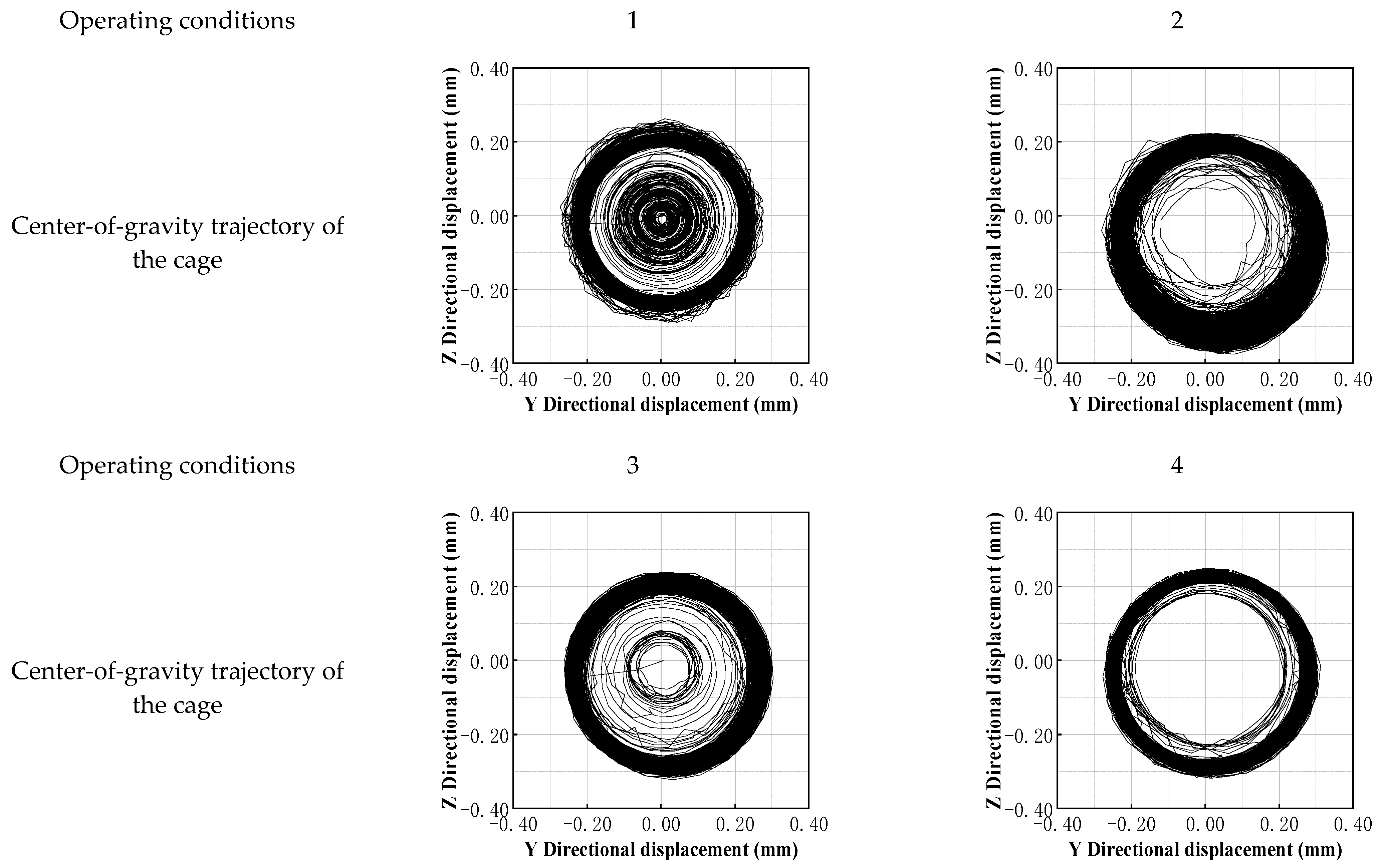
4.3. Vibration Characteristics of Bearings Under Changing Conditions

Under variable operating conditions, the vibration characteristics of bearings exhibit significant dynamic changes, with vibration signals exhibiting amplitude-modulated and frequency-modulated characteristics that are highly influenced by changes in rotational speed. These characteristics result in a more complex frequency spectrum for the vibration signals, including fundamental frequencies and their harmonics, accompanied by modulation phenomena. These characteristics indicate that under variable speed conditions, the vibration characteristics of bearings are not only related to speed changes but also closely associated with their internal structural parameters and operating environment. Therefore, to conduct an in-depth study of the vibration characteristics of bearings under variable operating conditions, it is essential to establish an accurate simulation model and validate the data. Based on the aforementioned characteristics, this section will further analyze the vibration behavior and underlying patterns of bearings under variable operating conditions using the dynamic simulation software Adams. All results in this chapter are derived from the dynamic simulation software.

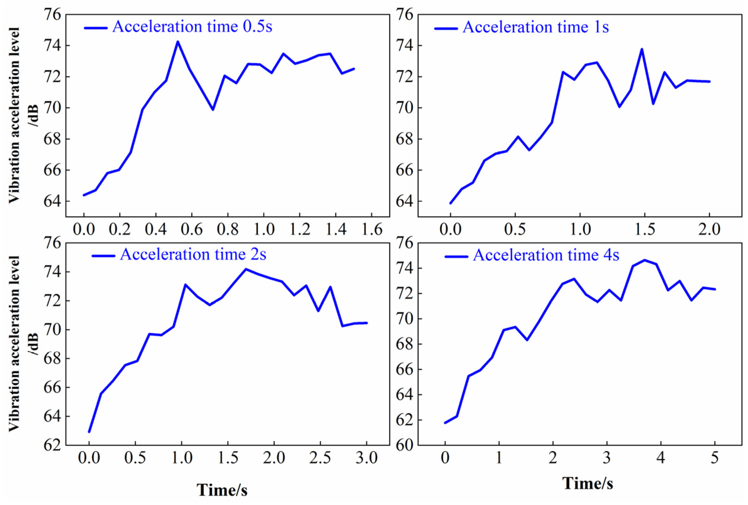
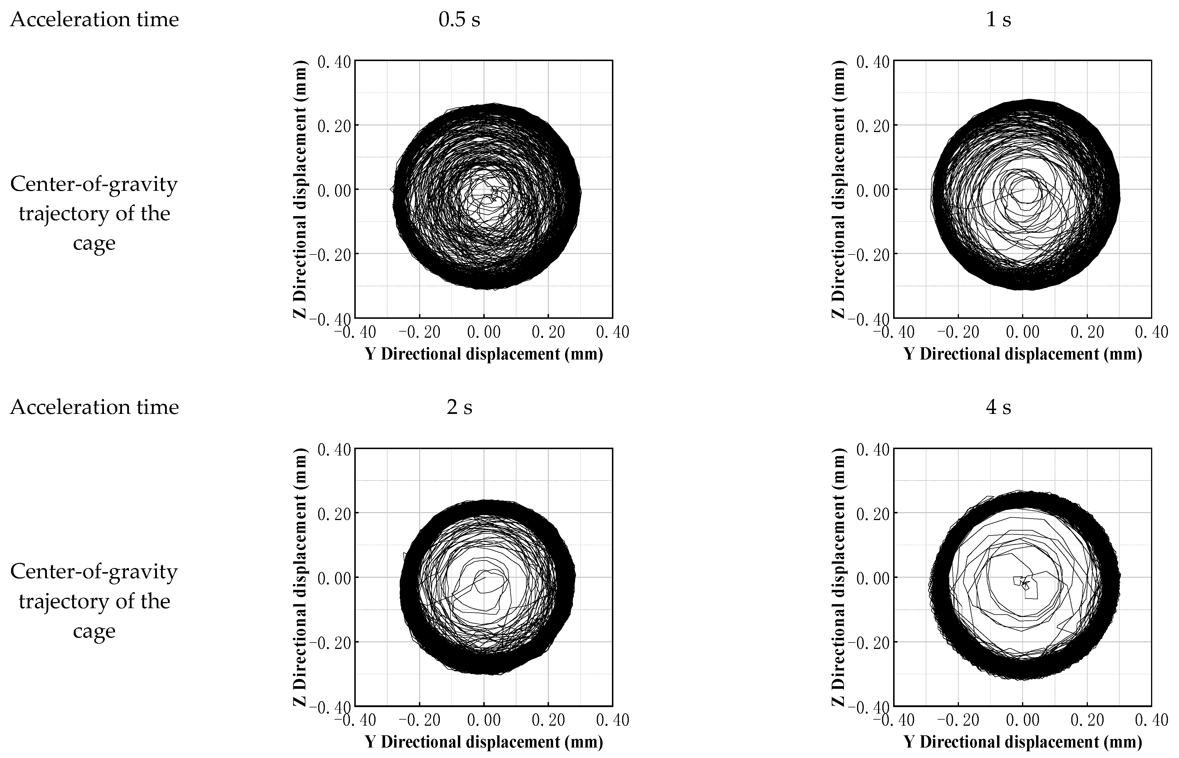
4.3.1. Effect of Acceleration Time on Vibration Characteristics

The acceleration process of angular contact ball bearings in aircraft engines during the startup phase has a significant impact on vibration characteristics, directly affecting system reliability and lifespan. This paper sets four acceleration times of 0.5 s, 1 s, 2 s, and 4 s to analyze the vibration response patterns of the bearing as it accelerates from rest to 10,000 rpm (followed by stable operation for 1 s), with an axial load of 200 N, a radial load of 300 N, and lubricating oil at room temperature. This enables a comprehensive evaluation of the dynamic response and performance of the bearing during different speed transition processes. This research helps reveal the influence patterns of acceleration time on bearing vibration characteristics, particularly the generation patterns of nonlinear vibrations.
Figure 3 shows the vibration characteristics of angular contact ball bearings in aircraft engines under different acceleration times (0.5 s, 1 s, 2 s, and 4 s). In tests where the bearing acceleration time was gradually extended from 0.5 s to 4 s, the changes in vibration acceleration levels showed a nonlinear relationship, first decreasing and then stabilizing or slightly increasing, rather than strictly decreasing monotonically. This reveals the nonlinear influence of acceleration strategies on vibration responses, enabling the development of targeted optimization strategies based on these findings.
The results indicate that a 2 s acceleration time achieves the optimal balance between vibration suppression and efficiency. Short acceleration times (0.5 s to 1 s) result in severe vibration (maximum vibration level of 74.3, 73.8 dB) due to inertial impact and poor lubrication, with significant residual transient energy. Long acceleration times (4 s), while reducing transient impact, cause high-frequency noise due to heat accumulation and boundary lubrication friction, causing the steady-state vibration average to rise back to 72.3 dB. Medium-speed acceleration (2 s) achieves the lowest steady-state average (70.4 dB) and a pure spectrum by fully establishing the lubrication film and avoiding critical speeds, confirming it as the optimal operating condition. This study also identified abnormal vibration peaks (e.g., 74.3 dB at 0.5 s and 74.6 dB at 4 s).

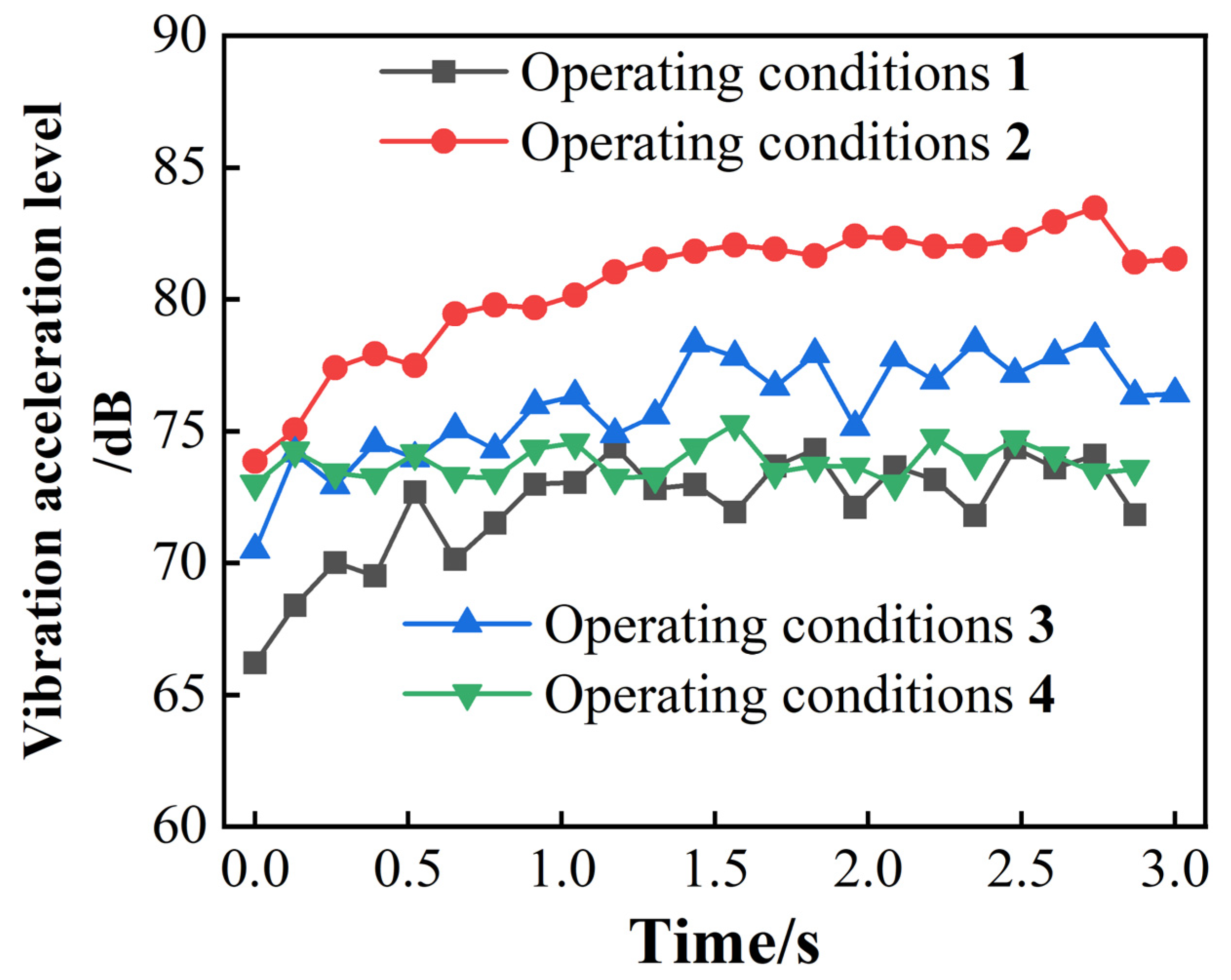
4.3.2. Dynamic Characteristic Analysis of Bearings Under Variable Load Conditions

Variable load conditions are another important area of research in bearing operation, especially in actual operation, where bearings may need to withstand impact loads or be rapidly loaded to target loads in a short period of time. Through a comparison of vibration data under different load conditions, the impact of load changes on bearing dynamic characteristics can be further analyzed, providing theoretical support for the performance evaluation and fault prediction of bearings under complex operating conditions.
To comprehensively assess the impact of axial and radial forces on bearing vibration, this study designed four typical operating conditions (Table 2), comprising axial force-dominated, radial force-dominated, axial–radial coupled, and high-load synchronous load conditions. As shown in Figure 3, a 2 s acceleration time achieves the optimal balance between vibration suppression and efficiency. Therefore, the load increase time for the four typical operating conditions is also set to 2 s. The remaining operating conditions include a rotational speed of 10,000 r/min and lubricating oil at room temperature. These conditions simulate the complex load variations that may be encountered in actual engineering applications, aiming to reveal the patterns of change in vibration acceleration levels under different load conditions and their underlying mechanisms. Through simulation analysis, the independent effects of axial and radial forces on bearing vibration, as well as the complex vibration characteristics under coupled effects, can be clearly observed. The results are shown in Figure 4 below.
The vibration characteristics of the four operating conditions in Figure 4 differ significantly. Under varying axial forces (50–500 N), the vibration acceleration level increased from 66.2 dB to 74.4 dB, with relatively small fluctuations (±2 dB), but the data for the last second is missing, making the trend incomplete. Under varying radial forces (100–1000 N), the vibration level increase is the largest (+9.7 dB), with a peak of 83.5 dB, and overall fluctuations are severe (±2.5 dB), indicating that radial force changes have a higher sensitivity to vibration. Under the dual-variable-force condition (axial and radial forces increasing synchronously from 200 N to 800 N), the vibration level fluctuated irregularly between 70.5 and 78.5 dB without increasing with force values, exhibiting the worst stability; meanwhile, under the constant force (1000 N) condition, the vibration level ranged from 72.9 to 75.3 dB with the smallest fluctuation (±1.2 dB), demonstrating the best stability.
The dynamic changes in radial force have a significantly greater impact on vibration than axial force, possibly due to the bearing structure being more sensitive to radial loads. The abnormal fluctuations in the dual-variable-force condition suggest a coupling effect between axial and radial forces, which may induce nonlinear vibration or resonance, necessitating further verification of the force interaction mechanism. Under constant high force values (1000 N), vibration is minimal and stable, indicating that the system tends toward equilibrium under steady-state loads, with more uniform energy dissipation, thereby reducing vibration responses caused by dynamic excitation.
To reduce vibration, priority should be given to controlling the dynamic range of radial forces, avoiding rapid adjustments to minimize fluctuations; in dual-force conditions, resonance frequencies should be identified through experiments or simulations, and force values should be optimized to avoid coupling effects. Additionally, in bearing operating conditions, high radial force conditions should be avoided. In summary, in practical applications, it is necessary to comprehensively consider the dynamic changes in axial and radial forces and their coupling effects to achieve the objective of optimizing bearing performance and reliability.

4.4. Analysis of the Correlation Between the Center-of-Gravity Trajectory of the Cage and Bearing Vibration

As a guide component for rolling elements, the stability of the center-of-gravity trajectory of the cage directly affects the dynamic characteristics of the bearing. Through a comparative analysis of the center-of-gravity trajectory of the cage under different acceleration times (as shown in Figure 5), it was found that its morphological characteristics are significantly correlated with the vibration acceleration level.
Figure 5 shows that acceleration time has a decisive influence on the shape and vibration characteristics of the cage center-of-gravity trajectory (e.g., the trajectory is disordered at 0.5 s acceleration and less smooth at 4 s acceleration), while dynamic load changes also play a key role in bearing stability. In the actual operation of aircraft engines, instantaneous load fluctuations (such as stepwise increases in axial force or radial–axial coupled sweeping frequencies) can further disrupt the stability of the cage center-of-mass trajectory by altering the distribution of contact stress, the coordination of rolling-element motion, and lubrication conditions. Such disruptions not only amplify the nonlinear response of vibration acceleration levels but may also induce potential risks such as rolling-element collision disorder and localized wear.
To elucidate the regulatory mechanism of load in the trajectory of the cage center of gravity, based on four typical operating conditions (axial force-dominant, radial force-dominant, coupled type, and equal-amplitude synchronous type), combined with simulation data, the dynamic evolution law of the cage center-of-gravity trajectory during variable load conditions is analyzed (as shown in Figure 6), elucidating the bidirectional effect of dynamic loads on vibration suppression and bearing stability, and providing theoretical support for load optimization strategies under complex operating conditions.
Figure 6 shows that during the operation of rolling bearings, different types of loads result in distinct mechanisms of trajectory evolution, which significantly impact bearing performance and reliability. In axial force-dominated conditions, the stepwise increase in axial load disrupts the symmetrical loading of the cage, leading to uneven distribution of contact stress and causing trajectory disruption. Additionally, the hysteresis effect of the lubricating oil film exacerbates friction-induced vibrations between the rolling elements and the cage, causing high-frequency oscillations in the trajectory. In contrast, in radial force-dominated conditions, as radial loads increase, the contact area of the rolling elements concentrates toward the load direction, and lateral compression causes the center of mass of the cage to shift, resulting in a significant increase in the circularity error of the trajectory. Furthermore, the increased centrifugal force effect further disrupts the coordination of motion, and the fluctuations in vibration acceleration levels are generally consistent.
In axial–radial coupled conditions, the cage center-of-mass trajectory is nearly circular but accompanied by local fluctuations. The dynamic changes in axial and radial forces trigger frequent adjustments in the contact stress distribution, causing the contact state between the rolling elements and raceway to continuously change. This results in asymmetric loads disrupting the coordination of rolling-element motion, with partial slippage or collisions affecting cage stability. By the closed-loop control of the center-of-mass trajectory (e.g., an ideal circular ring), vibration peaks can be suppressed, and the risk of rolling-element disorder reduced, thereby achieving dynamic stability optimization. In contrast, the constant-amplitude synchronous operating condition exhibits entirely different characteristics: under constant high loads, the contact stress distribution is uniform, the circularity error of the trajectory is minimal, and the vibration acceleration level is stable. This demonstrates the superiority of angular contact ball bearings as aviation bearings and validates the decisive role of load symmetry in motion stability.
The above analysis provides a simple examination of the bearing cage center-of-mass trajectory. However, directly comparing the morphology of the cage center-of-mass trajectory is insufficient for quantitatively assessing bearing cage stability. Introducing the center-of-mass vortex radius deviation ratio as a quantitative metric allows for an objective characterization of the degree of cage motion instability, significantly enhancing the reliability and comparability of conclusions, as shown in Figure 7.
Testing bearing performance under different acceleration times revealed the following results: The eccentricity ratios of the cage center of mass for acceleration times of 0.5 s, 1 s, 2 s, and 4 s were 0.22043, 0.15927, 0.096197, and 0.116197, respectively. Among these, the acceleration time of 2 s resulted in the smallest eccentricity ratio (0.096197). Additionally, the overall vibration acceleration level of the bearing also reached its relatively lowest level under the 2 s condition. This indicates that the stability of cage motion (minimum vortex deviation ratio) and the bearing’s overall low vibration performance (minimum vibration acceleration level) are optimal under the 2 s acceleration condition, and their trends are consistent.
Comparing bearing performance under four load conditions yielded the following results: In the axial force-dominated condition (Condition 1), the stepwise increase in axial force may cause changes in internal preload or fluctuations in raceway contact conditions, which can suppress overall vibration (low acceleration level) but may lead to uneven force distribution on the cage, resulting in a disordered center-of-mass trajectory (maximum deviation ratio of 0.45686). In the radial force-dominated condition (Condition 2), the significantly increasing radial force directly induces radial vibration in the bearing (highest acceleration level), but the load direction remains relatively stable, so the cage movement offset is relatively controllable (deviation ratio of 0.13858 is acceptable). In the axial–radial equal-amplitude synchronous type (Condition 4), the system is most stable due to constant load and coupled balance, resulting in minimal vibration fluctuations and the best cage trajectory circularity (deviation ratio of 0.097843, the smallest). The coupled type (Condition 3) may induce a wide-frequency response during dynamic sweep testing.
The above research provides an important basis for the performance evaluation and reliability design of bearings under different conditions.

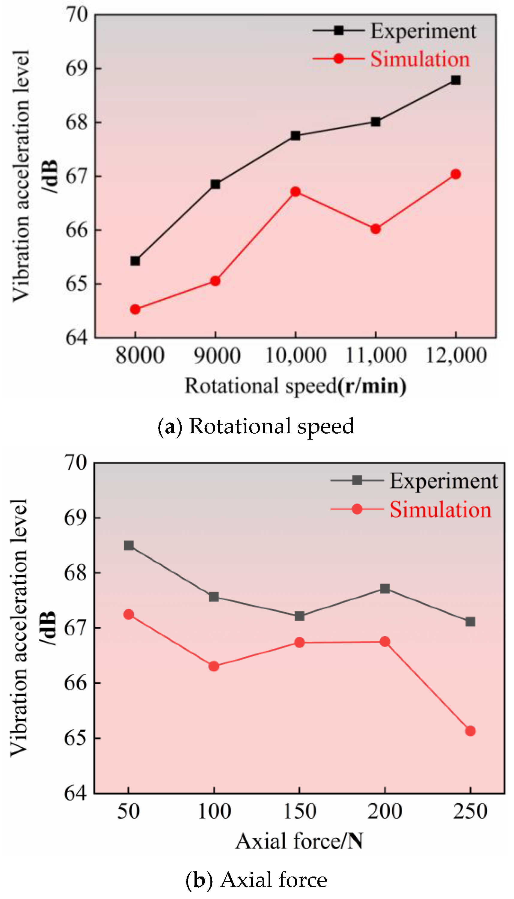
5. Simulation and Experimental Data Verification

The vibration characteristics of angular contact ball bearings in aircraft engines under varying operating conditions directly affect their service life and reliability. Previously, by establishing a multi-physics coupled dynamic simulation model, we systematically analyzed the vibration response patterns under four typical operating conditions: axial force and radial force stepwise increase, dynamic sweep frequency, and high-frequency small-amplitude vibration. Additionally, we investigated the transient vibration evolution characteristics of the bearing from rest to rated speed under different acceleration times (0.5 s, 1 s, 2 s, 4 s), revealing the nonlinear mechanisms of load–vibration transmission and resonance risks. However, the accuracy of the simulation model must be validated through experimental comparison. To this end, this study established a vibration test apparatus for angular contact ball bearings and conducted simulation and experimental comparison analyses of steady-state vibration acceleration levels under different operating conditions (Figure 8).
In this experimental section, a total of 15 operating conditions (as shown in Table 3) were designed, including different speeds, radial loads, and axial loads, comprehensively covering the vibration characteristics of bearings under variable operating conditions to ensure the comprehensiveness and reliability of the experimental data. The experimental and simulation results are outlined below.
As shown in Figure 8, in ADAMS simulation software, the operating state of the bearing under constant load conditions was simulated, and the vibration acceleration simulation data of the bearing under steady-state conditions were obtained. At the same time, experimental tests were conducted under the same operating conditions, and the actual vibration acceleration data during operation were recorded. The simulation results were compared with the experimental data after vibration acceleration level processing, indicating that the two have good consistency, thereby verifying the validity and accuracy of the simulation model.
As shown in Figure 8, changes in radial force have the greatest impact on bearing vibration intensity. When the radial force increases from 300 N to 700 N, the vibration acceleration level significantly increases, with a large change amplitude. In contrast, changes in axial force and rotational speed have a relatively smaller impact on the vibration acceleration level. The influence of axial force on bearing vibration intensity exhibits a nonlinear characteristic. Changes in axial force primarily affect vibration acceleration levels through factors such as shaft alignment, bearing operating conditions, and shaft bending. At low axial force levels, increasing axial force helps reduce vibration; however, beyond a certain threshold, other factors may cause vibration to increase until the axial force becomes sufficiently large to reduce vibration again. Therefore, when the rotational speed and radial force are constant, there exists an optimal range of axial force that minimizes bearing vibration intensity. Changes in rotational speed also have a relatively small effect on vibration acceleration levels, but as rotational speed increases, vibration acceleration levels generally show an upward trend. Although experimental data did not directly include the center-of-mass trajectory of the cage, the overall bearing vibration signals in the simulation highly matched the experimental vibration signals, indirectly verifying the reliability of the center-of-mass trajectory model.
It is worth noting that appropriate axial force can reduce bearing vibration, while radial force and rotational speed both increase bearing vibration intensity, with radial force having the greatest impact. Therefore, in daily machine operations, it is advisable to avoid excessive radial force whenever possible, while also reasonably controlling axial force and rotational speed to optimize bearing performance and reduce vibration.

6. Conclusions

This study reveals the pivotal role of transient process control in enhancing bearing stability, particularly the fundamental impact of the time scale of the startup process on stability. The research indicates that an appropriate acceleration time is critical for balancing the effective formation of the bearing lubrication film and the dissipation of inertial forces, thereby effectively avoiding critical speed disturbances and suppressing nonlinear vibrations. Further analysis indicates that the dynamic changes in radial forces are the dominant factor in system vibrations. Compared to axial forces, fluctuations in radial forces have a more sensitive impact on vibration intensity and stability, and are more likely to trigger severe fluctuations. Additionally, the coupled interaction between axial and radial forces significantly exacerbates the system’s nonlinear response and resonance risks. In terms of steady-state operation, the symmetrical load condition under constant high load exhibits optimal performance, where contact stress distribution is uniform, system energy dissipation is balanced, and vibration fluctuations are minimal. Therefore, in practical applications, prioritizing the suppression of sudden changes in radial forces is critical, and optimizing the matching of axial forces can synergistically enhance the overall stability of the bearing.

Author Contributions

Conceptualization, Y.D. and Z.Y.; methodology, Y.D.; software, Y.D.; validation, Y.D., Z.Y., J.S. and J.J.; formal analysis, Y.D.; investigation, Y.D.; resources, Y.D. and W.Y.; data curation, Y.D. and H.Z.; writing—original draft preparation, Y.D.; writing—review and editing, Y.D.; visualization, Y.D. and W.Z.; supervision, Y.D.; project administration, Y.D.; funding acquisition, Z.Y. All authors have read and agreed to the published version of the manuscript.

Funding

This research was funded by the National Natural Science Foundation of China Young Scientist Program (52205096) and the Open Fund Project of the National Key Laboratory of Interface Science and Technology for Advanced Equipment, Tsinghua University (SKLTKF24B09).

Data Availability Statement

Restrictions apply to the datasets: The datasets presented in this article are not readily available because the data are part of an ongoing study. Requests to access the datasets should be directed to xiaoqidong104@163.com.

Conflicts of Interest

Authors Dong Yanfang and Zhang Hai were employed by the company Suzhou Bearing Factory Co., Ltd. And author Sun Jianyong was employed by the company Luoyang Bearing Research Institute Co., Ltd. The remaining authors declare that the research was conducted in the absence of any commercial or financial relationships that could be construed as a potential conflict of interest.

References

  1. Zeng, Q.; Xu, P.; Meng, Z.; Ma, C.; Lei, X. Posture and Dynamics Analysis of Hydraulic Support with Joint Clearance under Impact Load. Aerospace 2023, 11, 159. [Google Scholar] [CrossRef]
  2. Guo, B.; Wu, W.; Zheng, J.; He, Y.; Zhang, J. Dynamics Modeling and Analysis of Rolling Bearings Variable Stiffness System with Local Faults. Aerospace 2023, 11, 609. [Google Scholar] [CrossRef]
  3. Alwadie, A. The Decision Making System for Condition Monitoring of Induction Motors Based on Vector Control Model. Aerospace 2017, 5, 27. [Google Scholar] [CrossRef]
  4. Lourari, A.W.; Soualhi, A.; Medjaher, K.; Benkedjouh, T. New Health Indicators for the Monitoring of Bearing Failures under Variable Loads. Struct. Health Monit. 2024, 23, 2922–2941. [Google Scholar] [CrossRef]
  5. Yu, A.; Huang, H.Z.; Li, Y.F.; Yang, W.; Deng, Z. A Modified Nonlinear Fatigue Damage Accumulation Model for Life Prediction of Rolling Bearing under Variable Loading Conditions. Fatigue Fract. Eng. Mater. Struct. 2022, 45, 852–864. [Google Scholar] [CrossRef]
  6. Pang, X.; Zhu, D.; Zuo, X.; Wang, D.; Hao, W.; Qiu, M.; Liu, D. Analysis of Rigid-Flexible Coupled Collision Force in a Variable Load Offshore Wind Turbine Main Three-Row Cylindrical Roller Bearing. Lubricants 2024, 12, 252. [Google Scholar] [CrossRef]
  7. Hamadache, M.; Lee, D.; Veluvolu, K.C. Rotor Speed-Based Bearing Fault Diagnosis (RSB-BFD) under Variable Speed and Constant Load. IEEE Trans. Ind. Electron. 2015, 62, 6486–6495. [Google Scholar] [CrossRef]
  8. Wang, X.B.; Luo, L.; Tang, L.; Yang, Z.X. Automatic Representation and Detection of Fault Bearings in In-Wheel Motors under Variable Load Conditions. Adv. Eng. Inform. 2021, 49, 101321. [Google Scholar] [CrossRef]
  9. Han, Q.; Li, X.; Chu, F. Skidding Behavior of Cylindrical Roller Bearings under Time-Variable Load Conditions. Int. J. Mech. Sci. 2018, 135, 203–214. [Google Scholar] [CrossRef]
  10. Zhao, W.; Wang, Z.; Cai, W.; Zhang, Q.; Wang, J.; Du, W.; He, X. Multiscale Inverted Residual Convolutional Neural Network for Intelligent Diagnosis of Bearings under Variable Load Condition. Measurement 2022, 188, 110511. [Google Scholar] [CrossRef]
  11. Moshrefzadeh, A. Condition Monitoring and Intelligent Diagnosis of Rolling Element Bearings under Constant/Variable Load and Speed Conditions. Mech. Syst. Signal Process. 2021, 149, 107153. [Google Scholar] [CrossRef]
  12. Fang, B.; Zhang, J.; Yan, K.; Hong, J.; Wang, M.Y. A Comprehensive Study on the Speed-Varying Stiffness of Ball Bearing under Different Load Conditions. Mech. Mach. Theory 2019, 136, 1–13. [Google Scholar] [CrossRef]
  13. Fan, H.; Ren, Z.; Zhang, X.; Cao, X.; Ma, H.; Huang, J. A Gray Texture Image Data-Driven Intelligent Fault Diagnosis Method of Induction Motor Rotor-Bearing System under Variable Load Conditions. Measurement 2024, 233, 114742. [Google Scholar] [CrossRef]
  14. Tu, W.; Liang, J.; Yu, W.; Shi, Z.; Liu, C. Motion Stability Analysis of Cage of Rolling Bearing under the Variable-Speed Condition. Nonlinear Dyn. 2023, 111, 11045–11063. [Google Scholar] [CrossRef]
  15. Wang, B.; Liu, Y.; Zhang, B.; Yang, S. Development and Stability Analysis of a High-Speed Train Bearing System under Variable Speed Conditions. Int. J. Mech. Syst. Dyn. 2022, 2, 352–362. [Google Scholar] [CrossRef]
  16. Bisson, E.E.; Anderson, W.J. Advanced Bearing Technology; Office of Scientific and Technical Information, National Aeronautics and Space Administration: Washington, DC, USA, 1964; Volume 38.
  17. Randall, R.B.; Antoni, J. Rolling Element Bearing Diagnostics—A Tutorial. Mech. Syst. Signal Process. 2011, 25, 485–520. [Google Scholar] [CrossRef]
  18. Huang, H.; Baddour, N. Bearing Vibration Data Collected under Time-Varying Rotational Speed Conditions. Data Brief 2018, 21, 1745–1749. [Google Scholar] [CrossRef] [PubMed]
  19. Dolenc, B.; Boškoski, P.; Juričić, Đ. Distributed Bearing Fault Diagnosis Based on Vibration Analysis. Mech. Syst. Signal Process. 2016, 66, 521–532. [Google Scholar] [CrossRef]
  20. Lee, K.C.; Hong, D.K.; Jeong, Y.H.; Kim, C.Y.; Lee, M.C. Dynamic Simulation of Radial Active Magnetic Bearing System for High Speed Rotor Using ADAMS and MATLAB Co-Simulation. In Proceedings of the 2012 IEEE International Conference on Automation Science and Engineering (CASE), Seoul, Republic of Korea, 20–24 August 2012; IEEE: Piscataway, NJ, USA, 2012; pp. 880–885. [Google Scholar]
  21. Yao, T.; Wang, L.; Liu, X.; Huang, Y. Multibody Dynamics Simulation of Thin-Walled Four-Point Contact Ball Bearing with Interactions of Balls, Ring Raceways and Crown-Type Cage. Multibody Syst. Dyn. 2020, 48, 337–372. [Google Scholar] [CrossRef]
Figure 1. Schematic diagram of three-dimensional model and simulation model of bearing.
Aerospace 12 00623 g001
Figure 2. Spindle system.
Aerospace 12 00623 g002
Figure 3. Vibration acceleration level change curve of bearings under different acceleration times.
Aerospace 12 00623 g003
Figure 4. Comparison of bearing vibration acceleration levels under four typical operating conditions.
Aerospace 12 00623 g004
Figure 5. Trajectory diagram of the center of gravity of the cage under different acceleration times.
Aerospace 12 00623 g005
Figure 6. Trajectory diagram of the center of gravity of the bearing cage under four typical operating conditions.
Aerospace 12 00623 g006
Figure 7. Center-of-gravity vortex radius deviation ratio of bearing cage center-of-gravity trajectory data.
Aerospace 12 00623 g007
Figure 8. Comparison of vibration acceleration levels for various bearing operating conditions under a single variable.
Aerospace 12 00623 g008aAerospace 12 00623 g008b
Table 1. Technical specifications of the test rig.
Test SubjectAngular Contact Ball Bearing
Number of tests4 sets
Bearing inner diameterΦ20–Φ60 mm
Maximum radial load4 kN (closed-loop control)
Maximum axial load2 kN (closed-loop control)
Test bearing speed2000–32,000 r/min
High-temperature lubricant heatingRoom temperature to 180 °C (electric heating)
Test parametersBearing vibration, temperature, load, etc.
Lubrication methodSpray lubrication
Table 2. Four typical operating conditions for aviation bearings.
Operating ConditionsAxial Force Fa/NRadial Force Fr/NLoad Coupling CharacteristicsSimulated Engineering Background
150 → 500 (Stepwise increase)Constant 300Axial force-dominant typeThrust changes during engine acceleration and deceleration
2Constant 300100 → 1000 (Stepwise increase)Radial force-dominant typeCentrifugal force fluctuations during maneuvering flight
3200 → 800 (Stepwise increase)200 → 800 (Stepwise increase)Axial–radial coupled typeComposite dynamic load (dive/climb)
4Constant 1000Constant 1000Axial–radial equal-amplitude synchronous typeHigh-load conditions during stable engine operation
Table 3. Bearing operating condition test table.
Test TypeExperiment NumberAxial Load/NRadial Load/NRotational Speed/rpm
Speed parameter series1–52003008000–12,000
Axial force parameter series6–1050–25030010,000
Radial force parameter series11–15200300–70010,000
Disclaimer/Publisher’s Note: The statements, opinions and data contained in all publications are solely those of the individual author(s) and contributor(s) and not of MDPI and/or the editor(s). MDPI and/or the editor(s) disclaim responsibility for any injury to people or property resulting from any ideas, methods, instructions or products referred to in the content.

