1. Introduction
Solid rocket motors (SRMs) have been widely used in military and aerospace fields because of their simple structure and easy storage. As the core power unit of spacecraft and missiles, the stable combustion of the SRM is crucial to the reliability of the whole system [
1]. However, an SRM is prone to unstable combustion when the combustion process is disturbed, which affects the reliability of the motor and the whole system. In the early days, about 50% of SRMs had different degrees of combustion instability problems in the working process, and in 10–15%, developers were forced to extend the development period [
2]. Combustion instability is an abnormal working state and involves the interaction of multiple physicochemical processes. Aluminum, a common propellant component, significantly impacts combustion stability through its high-temperature material behavior, particle combustion, and oxidation processes. For instance, the oxidation of aluminum particles during combustion forms an oxide cap, which not only affects particle combustion efficiency but can also alter the pressure oscillation characteristics within the combustion chamber. Additionally, the combustion properties of propellants under different environmental conditions are uncertain. Particularly, safety issues like incomplete combustion or flameout in low-pressure environments require in-depth research. These factors collectively make the combustion process of solid rocket propellants highly challenging. To better understand and control combustion instability, it is essential to consider the high-temperature behavior of aluminum materials, particle combustion and oxidation, oxide cap formation, uncertainty analysis, and the relationship between propellant orientation and combustion characteristics [
3,
4,
5]. When combustion instability occurs, the pressure in the combustion chamber changes drastically; it will cause unexpected phenomena, such as flameout or explosion. Therefore, it is of great significance to conduct in-depth research on the combustion instability behavior of SRMs and obtain the combustion instability mechanism or influencing factors for improving the safety and reliability of SRMs.
Combustion instability is closely related to the acoustic characteristics within the combustion chamber. Under certain conditions, if 0.14% of the energy released by propellant combustion is converted into acoustic energy, the pressure amplitude can reach 10% of the average pressure in the combustion chamber [
6]. The combustion cavity in SRMs serves as a low-loss acoustic cavity containing a massive acoustic energy source (the combustion process itself), and a small fraction of the energy released during combustion is sufficient to excite unacceptable levels of pressure oscillations. The acoustic characteristics of the internal structures of the motor can significantly impact combustion behavior. Therefore, to accurately characterize the combustion stability of the motor, researchers typically initiate their studies by investigating the acoustic cavity frequencies and modal behaviors of the motor [
7,
8,
9]. Moreover, the acoustic damping characteristics are also one of the important influencing factors in the study of combustion instability. Some scholars have studied the gain and damping characteristics of the combustion chamber structure as well as the coupling relationships between gain factors, providing theoretical guidance for motor design and stability analysis [
10,
11,
12,
13]. In addition, existing research shows that different grain structure designs will change the modal characteristics of the sound field in the combustion chamber, having a significant impact on the damping coefficient. Therefore, analyzing the coupling relationship between different grain structures and acoustic damping will contribute to the study of combustion instability in SRMs.
The combustion instability of SRMs can be classified into linear and nonlinear types. Culick and other researchers have conducted a lot of work on linear combustion instability and established a linear instability prediction method [
14]. However, the combustion behavior in SRMs is very complex. The linear stability theory can only determine whether the motor has a tendency for combustion instability. It cannot accurately predict the pressure amplitude at which combustion instability occurs. The linear stability theory also struggles to account for phenomena like limit amplitude, pulse triggering, and mean pressure shift. Some researchers also studied the nonlinear combustion instability problems. Blomshield conducted extensive experimental research on nonlinear combustion instability. By applying pulse excitation during the operation of a linearly stable motor, nonlinear phenomena can be observed arising from excited combustion instability and summarized relevant experimental conclusions on pulse-triggered unstable combustion [
15,
16]. This concept has also been gradually applied to numerical simulations for analyzing the stability of SRMs [
17].
In recent years, advances in numerical simulation technology have introduced new tools for studying combustion instability. Notably, large eddy simulation (LES) has emerged as a prominent numerical method in this field. This method has facilitated rapid progress and deepened understanding in the research of combustion instability conditions, such as vortex–acoustic coupling and nonlinear combustion instability. Su et al. [
18] employed the LES numerical method to simulate the vortex–acoustic coupling phenomena within ramjet engines and SRMs, respectively. The LES method can capture the vortex motion patterns and pressure oscillation characteristics within the combustion chamber effectively. It is proving to be a powerful numerical tool for the study of combustion instability. Han et al. [
12] conducted a numerical study using the LES method to explore the influence of heat shield design parameters on the pressure oscillation characteristics caused by vortex–acoustic coupling effects, discovering that rational heat shield design could effectively reduce pressure oscillations. Xu et al. [
19] employed the LES method, accounting for complete conservation equations of mass, momentum, energy, and species concentrations while incorporating finite-rate chemical reaction kinetics in the gas phase for enhanced detail. The results indicate that the system is prone to enter a limit-cycle state when the frequency of small perturbations aligns with the acoustic mode frequency of the SRMs. Wang et al. [
20] analyzed the vortex–acoustic coupling pressure oscillation phenomenon and the mechanism of combustion instability during the late stages of solid rocket motor operation and proposed a method to suppress pressure oscillations using a head cavity, which provided theoretical guidance for engineering designers. These studies have provided important references for the development of stable, high-performance SRMs.
In the study of the combustion instability of SRMs, the pulse response characteristic is an important parameter. The pulse response describes the system’s output when subjected to a transient impulse, reflecting its reaction to instantaneous energy input. During the working time of SRMs, various factors both inside and outside the combustion chamber can potentially disturb the combustion process, such as propellant particle size, pressure fluctuations in localized regions, and oscillating combustion of solid propellants. These pulse excitations can lead to instantaneous pressure variations in the combustion chamber, thereby impacting the working conditions. Consequently, simulating disturbances through the pulse method and observing the resultant pressure variations within the combustion chamber can elucidate the chamber’s response characteristics to such perturbations. The pulse decay characteristic also serves as a crucial indicator for assessing the recovery properties of combustion after perturbations. Based on the Computational Fluid Dynamics (CFD) numerical simulation computation incorporating the idea of pulse experiments, the pressure oscillations can be obtained by applying a pulsed excitation to the combustion chamber. Most research has focused on head-triggered sources [
21,
22], while studies using pulsed triggers in combustion instability scenarios, such as sudden gas inlet changes and different combustion chamber regions, are relatively limited. In the actual working process of SRMs, if the motor interior is subjected to pulsed excitation effects, such as the shedding of propellant cladding materials or localized propellant ruptures, these can potentially cause a sharp, resulting in deviations of pressure amplitude from the average pressure, which can rapidly evolve into a state of limit amplitude, giving rise to nonlinear combustion instability phenomena.
The primary objective of this paper is to advance the understanding of combustion instability in SRMs with diverse finocyl grain configurations through numerical simulation. By employing the LES method, which is grounded in the principles of pulse decay experiments, this study meticulously analyzes the post-pulse pressure decay oscillations. The analysis is designed to elucidate the influence of varying grain structures on the dynamics of pressure oscillations and their subsequent decay. Additionally, this study scrutinizes the attenuation of pressure oscillations induced by impulse excitations at multiple locations within the SRM. The strength of this study lies in its systematic exploration of the pulse decay characteristics across different grain configurations, which has not been extensively explored in the current literature. The findings of this study enable the accurate prediction and effective mitigation of combustion instabilities in SRMs. Furthermore, this work is anticipated to significantly inform the design of more stable SRMs, providing a dual perspective on both acoustic and flow field considerations, thus enhancing the overall performance and safety of these critical propulsion systems.
2. Numerical Calculation Methods for Combustion Instability Analysis in SRM
2.1. Acoustic Finite Element Analysis
The foundation of studying nonlinear acoustic combustion instability is the acoustic mode and acoustic vibration mode analysis. The acoustic cavity structure of the combustor is very intricate, and the accuracy of theoretically estimated acoustic vibrational frequencies is compromised. Therefore, numerical computational methods such as finite element analysis (FEA) are generally employed to determine vibration modes of complex acoustic cavity structures.
Helmholtz’s equation is frequently utilized in acoustics to describe the propagation characteristics of wave phenomena. The equation postulates negligible pressure and density fluctuations, and it overlooks second-order terms, thus also referred to as the linear wave equation [
23]. Derived from the application of the linear wave equation in acoustic fluids, the equation for solving the acoustic pressure function is given as follows:
Here,
represents the complex wave number (
, where
represents the angular frequency,
represents the average sound velocity, and
represents the sound pressure).
For problems involving spatially heterogeneous media, by adding a mass source term to Equation (1), the equation can be expressed in the following form:
Furthermore, the general matrix form of the finite element can be derived as follows:
Here,
represents the structural mass matrix,
represents the structural damping matrix, and
represents the structural stiffness matrix. By employing the finite element method to discretize the three-dimensional wave equation, the element matrix form of the acoustic cavity modal equation can be derived as follows:
In Equation (4), represents the acoustic stiffness matrix, and represents the acoustic mass matrix. The acoustic eigenvectors and the eigenvalues can be obtained using the finite element method. By exploiting the correlation between the acoustic vibration frequency and the angular frequency, denoted as , the acoustic vibration frequency of the cavity as well as the sound pressure distribution can be derived.
In this paper, the ANSYS 2022 R1 was utilized to conduct the acoustic modal analysis on a specific combustion chamber cavity. Furthermore, the simulation results were compared with experimental results to validate the correctness of the simulation analysis method.
2.2. LES Numerical Simulation
Combustion instability can lead to pressure oscillation in the combustion chamber, necessitating a profound understanding of pressure oscillation characteristics and flow field behavior. This paper employed fluid dynamics methods to investigate the complex flow and combustion processes within the combustion chamber. Conventional simulation methods for fluid dynamics analysis encompass DNS, RANS, and LES. Compared with the other two methods, LES has advantages in combustion, aerodynamic noise, momentum transfer, and vortex shedding and is frequently employed in refined calculations of the internal flow field of SRMs. It can not only compute the acoustic wave motion induced by pressure oscillations [
24,
25] but also accurately capture the details of the transient flow field. Moreover, through the FFT, it can obtain the frequency distribution of acoustic modes, enabling more precise acoustic characteristic analysis. In addition, LES can effectively characterize the attenuation characteristics of low-frequency pulses during the acoustic—flow field coupling process and the system damping under complex charge configurations.
To conduct LES, firstly, a mathematical filtering model must be established to remove eddies with scales smaller than the filtering function from the instantaneous turbulence equations, thereby decomposing the equations that describe the large eddies. Secondly, the influence of the filtered small eddies on the large eddies must be considered. This is embodied by introducing an additional stress term, known as the subgrid-scale (SGS) stress, into the governing equations of the large eddy flow field. Therefore, it is necessary to first establish an SGS model.
Through the filtering function, each variable in the large-eddy motion equation is divided into two parts: (1) large-scale averaged component , which is the filtered variable and can be directly calculated during numerical simulation, and (2) small-scale variable , which is represented by a model and directly filtered out without consideration in the calculation.
The large-scale averaged component
, as a filtered variable, represents the mean value in the spatial domain and can be obtained by the following integral:
Here,
represents the selected flow region,
represents the spatial coordinates,
represents the filtering function, and its value determines the scale of vortices in the problem being solved.
By employing the filtering function to process the instantaneous N-S (Navier–Stokes) equations and the continuity equation, the governing equation set in the LES method can be derived as follows:
where
represents the SGS stress, which embodies the influence of small-scale vortex motions on the solution of the motion equation. Its expression is presented as follows:
Since
is an unknown variable, it needs to be represented using parameters from the SGS model. The SGS model selected in this paper is as follows [
26]:
where
is turbulent viscosity.
Utilizing the above-mentioned governing equations and SGS models, in conjunction with fluid finite element simulation software, enables an accurate representation of acoustic wave motion induced by pressure oscillations.
2.3. Verification of Numerical Methods
2.3.1. Verification of the FEM
To verify the validity of the acoustic FEM, the scaled-down model of the Ariane-5 P230 motor developed by Europropulsion, located in Kourou, French Guiana, and proposed by VKI was selected as the research object, as shown in
Figure 1 [
27,
28]. As the flow in the nozzle’s throat was choked, rendering the upstream flow subsonic and ensuring that supersonic flow from the lower end does not affect the upper end, our analysis focused solely on the model before the nozzle’s throat. To validate our method’s accuracy, we calculated the motor’s acoustic cavity modes and inherent vibro-acoustic frequencies and compared them with experimental results. The nozzle throat’s cross-section was designated as the radiation boundary, while zero-displacement constraints were applied to the rest of the model’s surface. The fluid elements within the acoustic cavity were set with a density of 1.3 kg/m
3 and a sound speed of 343 m/s [
29].
First, the mesh independence of the combustion chamber cavity was verified. The finite element modal analysis was carried out on models with different mesh sizes, and the simulated acoustic fundamental frequencies were compared with experimental results. As shown in
Table 1, the simulation with a mesh size of 2 mm had a smaller error, so this mesh size was used for subsequent modal analysis in this study.
Figure 2 details the first four axial acoustic cavity modes and sound pressure distributions. The natural frequency calculation results were compared with the experimental results from reference [
27], as shown in
Table 2. Comparing the first four numerical calculation results with the literature results, the maximum relative error does not exceed 4%, suggesting that the acoustic finite element simulation calculation accuracy meets the requirements for predicting the sound field.
2.3.2. Verification of the Numerical Simulation Method for LES
To validate the effectiveness of the LES method, the scaled-down model of the Ariane-5 P230 motor was also taken as the research object. To account for the computational workload, the model was simplified into a two-dimensional axisymmetric model, as shown in
Figure 3. It should be noted that the current study primarily focuses on the low-frequency domain. Combustion conditions are considered to have a relatively minor impact on the instability combustion mechanism. The cold flow model can exclude the influence of complex chemical reactions on the study of acoustic unstable combustion in the combustion chamber during the operation of solid rocket motors, which can reduce its interference with the acoustic instability characteristics in the combustion chamber. Thus, it enables a more direct analysis of the process of pressure oscillation decay under pulse excitation [
30]. Therefore, the simulation employed a non-reactive cold gas flow model. The boundary conditions, solution methods, and other settings were kept the same as those in the reference. The gas was simplified to a compressible ideal gas, and the fluid physical parameters are shown in
Table 3.
A constant mass flow rate was applied to the head end face, where cold airflow was injected axially with a mass flow rate set at 0.3 kg/s. The outlet was set as a pressure outlet at 10 kPa. The bottom of the computational domain was designated as a swirl symmetry axis, while the remaining boundaries were set as no-slip walls. A time step of 1 × 10⁻⁶ s was employed, and pressure monitoring points were placed within the fluid region to record oscillation pressure.
The monitoring points are located at the head point Point-1 (0.0115 m, 0.038 m) and the end cavity point Point-2 (0.366 m, 0.05 m), respectively. We used Fast Fourier Transform (FFT) to deal with the recorded oscillation pressure data, as shown in
Figure 4. The obtained characteristic frequencies are compared with the experimental results, as detailed in
Table 4.
The results in
Table 4 indicate that the first four frequencies corresponding to the peak pressure oscillation obtained based on the LES method agreed well with the theoretical results, with a maximum relative error less than 4.5%. Furthermore, at the first acoustic frequency (401 Hz), it can be found that the RMS amplitude at Point-2 was significantly higher than that at Point-1, and the variation trend of the amplitude was also in good agreement with the experimental results.
3. Pulse Attenuation Characteristic Analysis in SRM
The pulse decay method is a commonly used approach to quantify system damping. Rapid and smooth decay of pressure disturbance pulses within a short time frame (short relaxation time) indicates sufficient damping in the combustion process, which can effectively dissipate disturbance energy, indicating good combustion stability. Conversely, slow pulse decay, non-monotonic fluctuations, or long-period oscillations (long relaxation time) suggest inadequate damping within the combustion chamber, potentially leading to sustained or even amplified combustion fluctuations, indicative of poorer combustion stability in the system. By analyzing the pulse decay characteristics, the stability of the solid rocket motor combustion process can be accurately assessed.
This paper intends to analyze the combustion stability characteristics of motors with different structures using the pulse decay method. Firstly, an instantaneous pressure pulse is applied to a specific area within the combustion chamber at a precise instant to simulate disturbances in actual operation. Subsequently, the pressure response data are calculated in the combustion chamber after the pulse disturbance using the numerical simulation methods. At last, the decay behavior of oscillation pressure over time and the damping characteristics within the combustion chamber are evaluated. The paper also studied the effects of various parameters, such as different grain structures, various initial boundary conditions, and different triggering positions, on the pulse attenuation characteristics and combustion stability of SRMs.
3.1. Computational Models and Boundary Conditions
There are two typical structures, the front finocyl grain (M1) and the rear finocyl grain (M2), that are selected to conduct pulse attenuation studies, as shown in
Figure 5. The throat diameter is L = 0.082 m, and other dimensions are expressed using the throat diameter. In order to facilitate the analysis and discussion in the following sections, a dimensionless time treatment is applied to the engine working process. The dimensionless time is defined as T
n = t/t
total, where T
n represents the dimensionless time, t is the specific working moment, and t
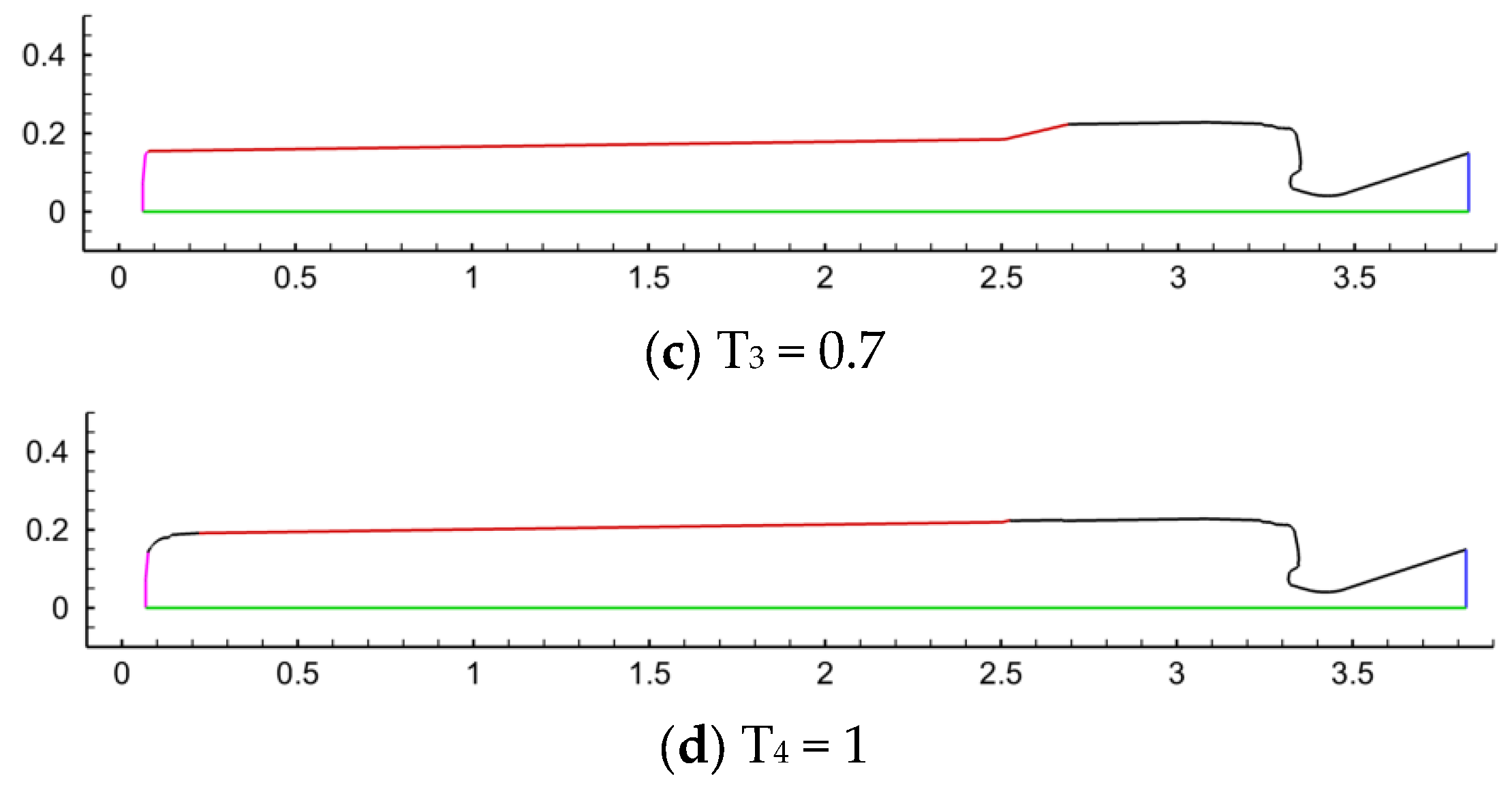
total is the total working duration. In the numerical model, the regression process of the burning surface is simulated in accordance with the parallel layer rule. During the combustion working stage, each burning surface regresses synchronously at a constant normal rate, and the geometric shape of the burning surface is calculated through the algebraic burning rate model. The established models at four dimensionless time instants of T
n = 0.1, 0.4, 0.7, 1 are shown in
Figure 6 and
Figure 7. The mass inlet flow rate is set to 25 kg/s, the pressure outlet is set to 10 kPa, and the temperature within the flow field region is 3500 K. Steady-state flow field calculation was performed first, with 2000 iterative steps. After convergence, unsteady-state calculation was initiated, using a time step of 1 × 10
−6 s. At t = 0.1 s into this calculation, a pulse (p
in = 18 MPa) was applied at the motor’s head end face boundary via UDFs (User-Defined Functions), to trigger and sustain pressure oscillations. After 30 time steps, the pressure response data during the natural decay process were recorded. The gas physical property parameters used in the flow field calculations are presented in
Table 5.
In the numerical simulation process, the steady-state flow fields of each model are calculated first. After the steady-state solution converges, the simulation switches to an unsteady-state framework. Then, pulsations are applied to the combustion chamber. After the motor works for a certain time, pulses are applied through UDFs to simulate the external excitations of the motor. Meanwhile, different monitor points, Point-1 (1.25 L, 0.625 L) and Point-2 (38.75 L, 1.875 L), are selected within the motor to record the decay process of pressure response data.
3.2. Mesh Dependency Verification
In CFD calculations, the computational resources consumed are much larger than those in acoustic FEA. Therefore, it is necessary to choose a suitable mesh scale for calculations. In the grid dependency verification, the model of the rear finocyl grain combustion chamber (M1) at T
2 = 0.4 was used to compare and verify the amplitude, decay, and frequency of pressure oscillations under four different mesh scales (as shown in
Table 6).
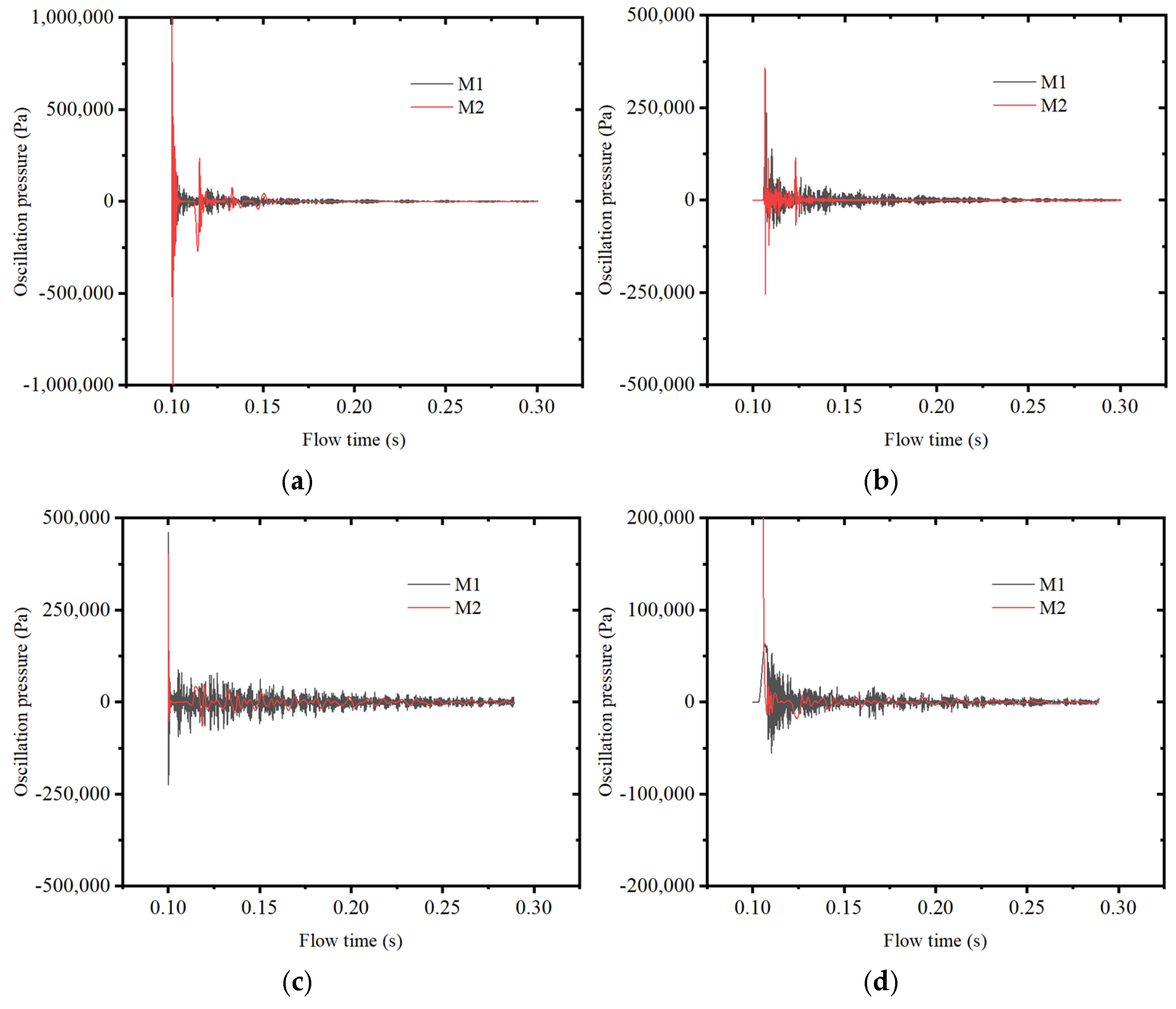
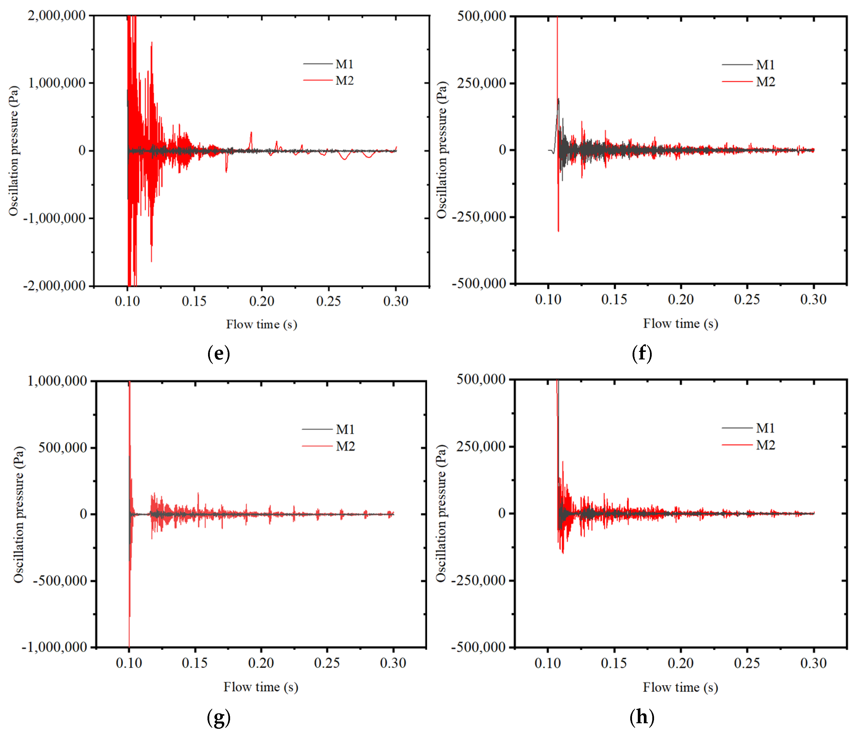
After the impulse excitation, the pressure oscillations at Point-1 and Point-2 in the calculation domain are shown in
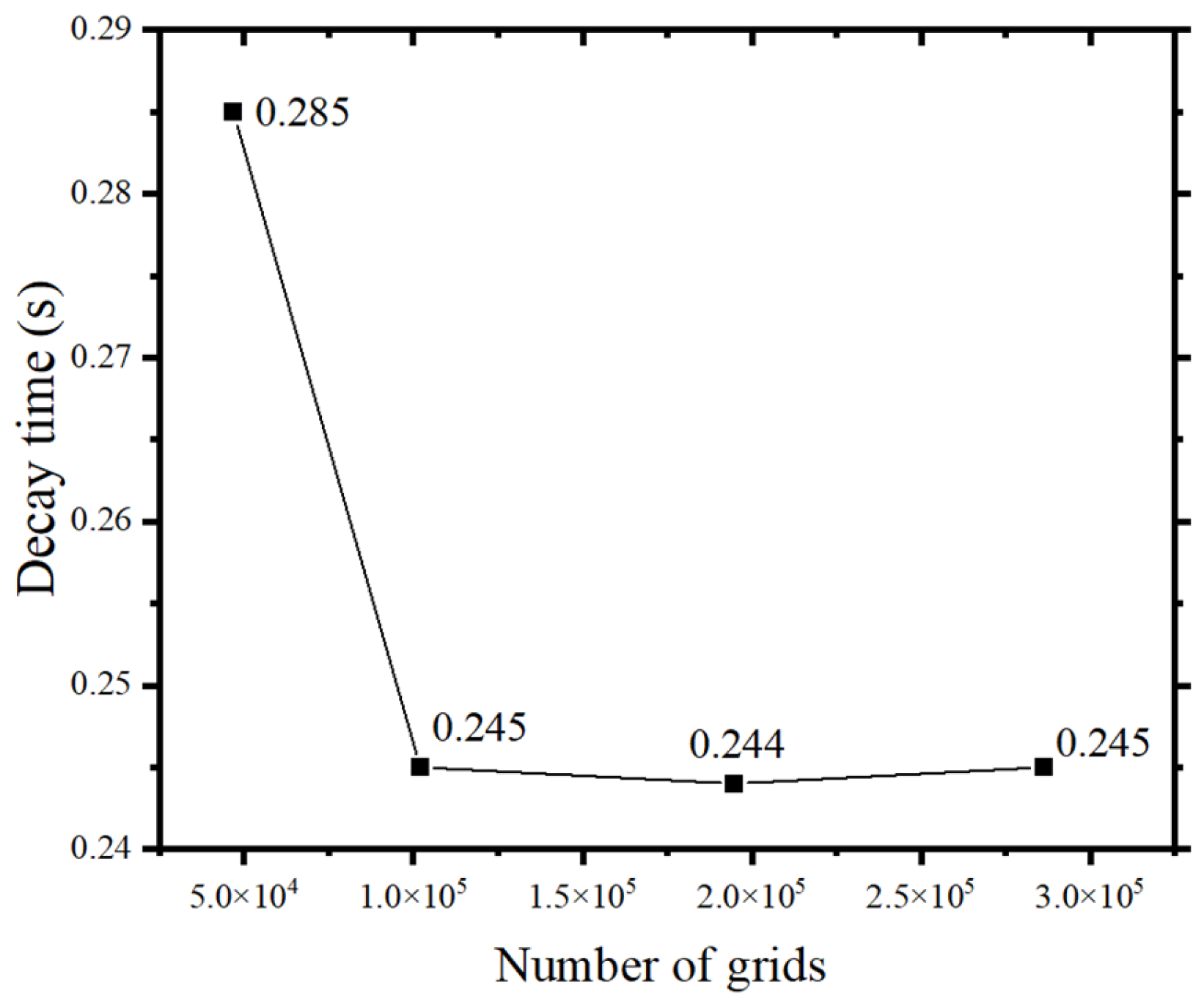
Figure 8. Under four mesh scales, the decay patterns of pressure oscillations at both points are consistent. Since the impulse pressure enters from the head of the combustion chamber, it attenuates due to fluid and wall damping during propagation, resulting in smaller oscillation amplitudes at Point-2 than at Point-1. All four meshes can well reflect these patterns, but the oscillation amplitudes differ with mesh size. As the number of grids increases, the time it takes for the pressure amplitude to decay to a steady state (below 2000 Pa) decreases significantly. For Mesh-1, the decay time is 0.285 s, while for Mesh-2, Mesh-3, and Mesh-4, the decay time stabilizes at approximately 0.245 s, as shown in
Figure 9.
Initially, both monitoring points show significant pressure decay. This is because in the nonlinear process of pressure oscillation, the nonlinear damping of the combustion chamber’s abrupt structural changes increases with the amplitude. However, in the Mesh-1 operating condition, the pressure oscillation amplitude is an order of magnitude larger than in other conditions. This is due to the inability of the coarse mesh to accurately capture the details of pressure oscillations, leading to an overestimated amplitude. The issue is notably improved when the mesh size is below a certain threshold, as seen in Mesh-2, Mesh-3, and Mesh-4.
To evaluate the performance of the four mesh sizes in the frequency domain, FFT was applied to the oscillating pressure data, as shown in
Figure 10. Since the data includes the late stage of pressure amplitude decay, the RMS amplitude is relatively small. The pressure oscillation frequencies from the four meshes show good consistency, with sharp and tall peaks at the acoustic fundamental frequency that gradually become flatter and shorter with increasing frequency. The frequency-domain results from the four meshes are physically reasonable and consistent with each other.
In Mesh-1, the coarsest mesh, the initial impulse amplitude is much higher than in Mesh-2, Mesh-3, and Mesh-4. Mesh-2, Mesh-3, and Mesh-4 produce valid numerical results that align with the expected pressure oscillation decay in the combustion chamber. Provided each time step’s iteration results converge reasonably, mesh sensitivity mainly comes from the mesh scale. Considering computational workload, to ensure pressure oscillation amplitude accuracy, the Mesh-3 mesh size is used for the subsequent analysis in this paper.
3.3. The Influence of Different Grain Structures on Pulse Decay
To investigate the influence of different grain configurations on pulse decay, a simulation analysis is conducted on the pulse attenuation during the working time of M1 and M2 models. The pressure variations over time at the same monitoring points are studied for different grain configurations by applying a rectangular pulse with a time step of 1 × 10
−5 s and calculating for 30 time steps over a duration of 0.3 ms [
22]. The location of the applied pulse excitation is taken as the head end face, with the pulse excitation set at pin = 18 MPa. The rectangular pulse is a typical transient excitation signal. During the work process of solid rocket motors, the pulse excitation generated due to reasons such as the shedding of aluminum powder exhibits the characteristics of the above-mentioned pulse signal, which is highly similar to the time–frequency characteristics of the rectangular pulse. Therefore, in this study, the rectangular pulse shown in
Figure 11 is selected to simulate the pulse excitation in the actual working process more realistically.
Figure 12 presents the pressure oscillation decay at various monitoring points after applying pulse excitation at different time points for the two types of grain structures.
According to the analysis presented in
Figure 12, aside from the operating instant T1 = 0.1, 0.4, the amplitude of pressure oscillation in the M2 is significantly higher than that of the M1 at all other working conditions. Point-1 (located at the head of the combustion chamber) and Point-2 (located at the rear of the combustion chamber) determine their phase relationship during acoustic oscillations. As the pulse pressure enters from the head of the combustion chamber, it undergoes attenuation due to fluid and wall damping during pulse propagation, resulting in a significantly lower oscillation amplitude at Point-2 compared to Point-1. Additionally, it can be observed that the pressure decay of M1 after pulse excitation is faster than that of M2. M1 requires a shorter time to restore the equilibrium state (the oscillation pressure amplitude approaches 0) after pulse excitation, indicating a shorter relaxation time. During one pressure oscillation cycle of M2, M1 undergoes multiple oscillations, potentially due to the interaction between unsteady flow caused by the abrupt structural change and acoustic factors.
The pulse pressure oscillations at three typical periods (T1 = 0.1, T2 = 0.4, and T4 = 1) of M1 and M2 are analyzed separately to compare the influence of grain configuration on the combustion stability of SRMs, as shown in
Figure 13.
It can be seen from
Figure 13 that the amplitude of the pulse pressure fluctuation in M2 is significantly lower than that in M1 under the same pulse excitation. It can be found that the front finocyl grain can effectively dampen pressure oscillation.
It can also be observed that as the working time progresses, the amplitude of the pressure oscillation increases. Furthermore, the attenuation of pressure after a pulse to its equilibrium state (when the amplitude of oscillation pressure approaches zero) is slower at the subsequent operating instant than at the preceding one, requiring a longer time for the pressure to restore equilibrium. This phenomenon also proved that the combustion instability in SRMs typically often occurs at the end of the working time.
3.4. The Influence of Different Trigger Conditions on Pulse Decay
Based on the coupling relationship between pressure oscillation and oscillatory combustion of propellant grains, changes in the mass flow rate of gas injected on the combustion surface can induce pressure disturbance and stimulate more significant combustion instability. To avoid the scenario where an insufficient characteristic amplitude of mass flow rate oscillations fails to trigger significant pressure oscillation, the inlet condition at the lateral burning surface is altered to a pressure inlet with pin = 10 MPa, serving as the pulse trigger condition under the realistic operating conditions. While maintaining the remaining boundary conditions unchanged, simulation analysis and calculations are conducted.
The pulse pressure decay at Point-1 is calculated at three typical periods: initial (T1 = 0.1), mid-front (T2 = 0.4), and final (T4 = 1) stages of M1 and M2 models, as shown in
Figure 14.
Figure 14 shows the amplitude and attenuation of pressure oscillations at different time instances. The analysis shows that under the same pulse excitation at the inlet of the propellant surface, the oscillating pressure starts to decay steadily (the amplitude of the oscillatory pressure is close to 0) at the computation time of 0.141 s and 0.145 s, respectively, for T1 = 0.1. At T2 = 0.4 condition, M1 and M2 start to decay steadily at 0.151 s and 0.154 s. M2 exhibits a slower pressure decay after the pulse compared to M1, and the amplitude of pressure oscillations due to pulse excitations in M2 is significantly higher than in M1. As the work progresses, the number of pressure peaks during the decay process of each motor gradually increases. Towards the end of the working time, both the M1 and M2 cavity structures become a cylindrical structure. Consequently, the decay rates of pressure oscillations in both motors are nearly the same. Additionally, compared with the initial and mid-to-front stages, pressure oscillation becomes more severe at the final stage, with more frequent pressure oscillations within the same time period. This observation reinforces that combustion instability tends to occur in the mid-to-late stages.
3.5. The Influence of Different Trigger Positions on Pulse Decay
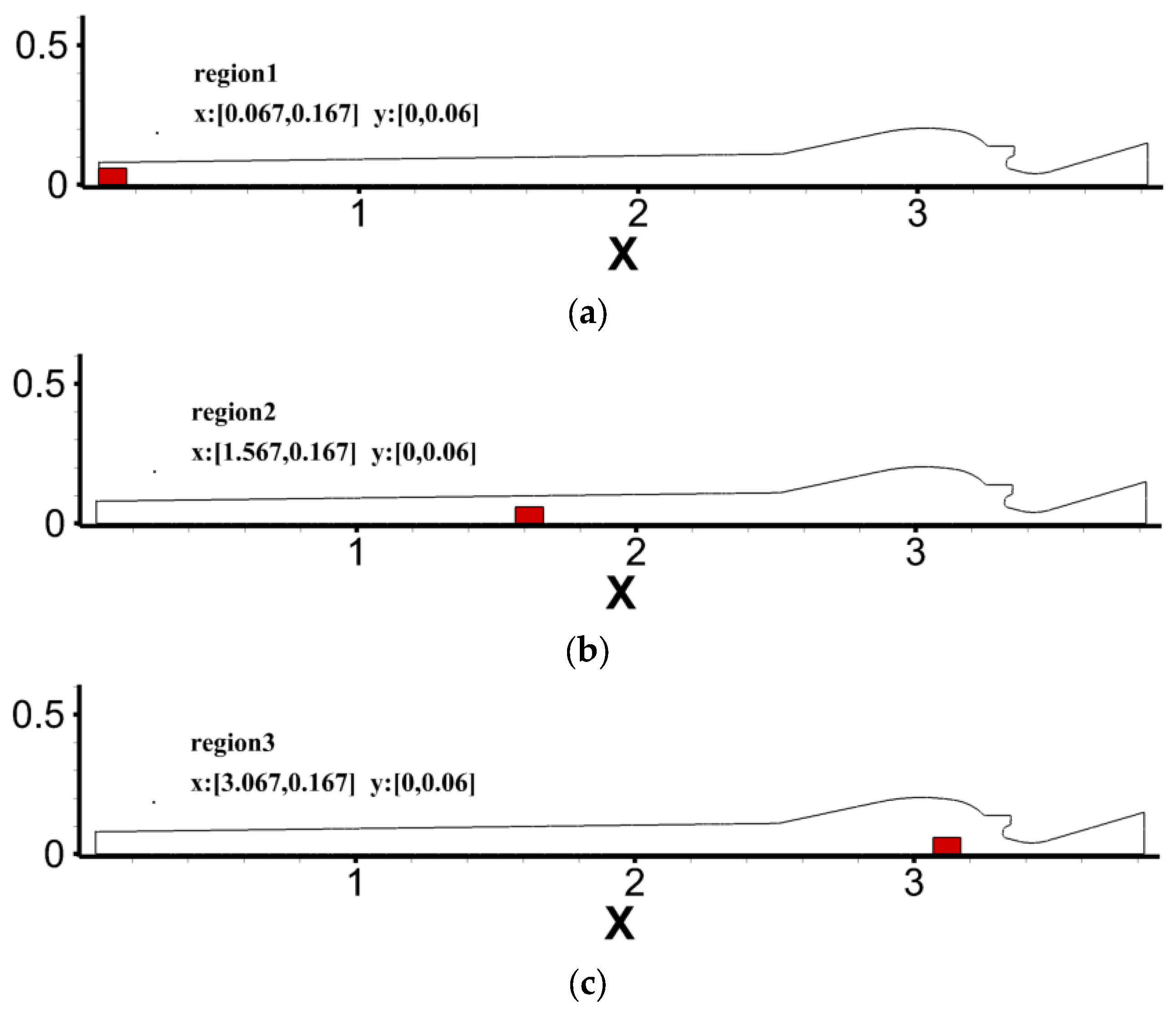
This section mainly studies the influence of different triggering positions on pulse decay. The excitation form is set as a rectangular pulse high-pressure zone distributed locally within the combustion chamber, initializing the pulse intensity in the local region to pin = 15 MPa Here, the axisymmetric structure of M2 at the working time T2 = 0.4 is selected as the research object, as shown in
Figure 15.
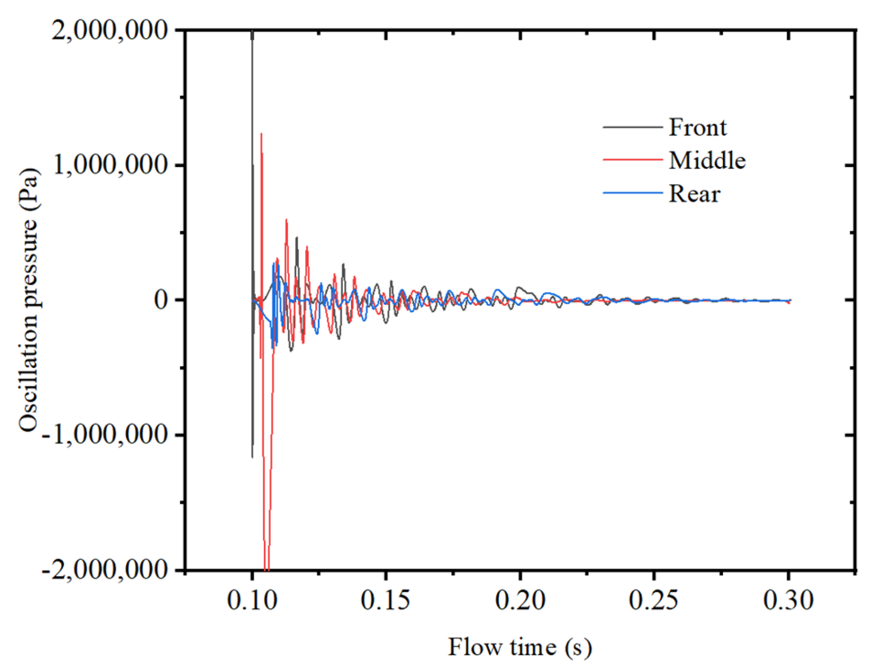
The influence of the pulse distribution zone on the decay of pressure oscillations in the combustion chamber of M2 at T2 = 0.4 is shown in
Figure 16.
As shown in
Figure 16, the pulse distribution zone does not affect the stable state eventually achieved by the combustion chamber oscillation but can indirectly influence the development and change path of system oscillation by affecting the initial pressure disturbance. Due to the different distributions of pulse zones, Point-1 located at the head experiences significant variations in the amplitude of pressure oscillations obtained through pulse excitation. When the pulse excitation is located at the middle and end, the maximum pressure amplitudes at Point-1 are 40.1% and 13.8% of that at the head. Here, it is considered that the pressure pulse decay tends to be stable when the pressure amplitude decreases to within 10,000 Pa. Comparing the time for the pulse oscillations to decay to a steady state under the three conditions, it is 0.227 s, 0.229 s, and 0.234 s. Therefore, the distribution of pulse zones has a relatively small influence on the pressure oscillation decay characteristics within the combustion chamber.
4. Conclusions and Discussion
This paper conducts a simulation analysis on the combustion stability in SRMs with finocyl grain. Using the LES method, the influence of different structures and pulse locations on pulse-triggered decay is investigated. The present results can provide a reference for predicting and controlling the combustion instability in SRMs for different grain structures. The main conclusions are shown as follows:
The present method is applied to the Ariane-5 P230 motor, and numerical simulations showed a good agreement with the experimental data, indicating that the LES method can effectively capture the pressure oscillation frequency.
The front finocyl grain structure proves more effective than the rear finocyl grain structure in attenuating pulsed fluctuating pressures. Additionally, it exhibits a shorter period of pressure stabilization decay, favoring the suppression of pressure oscillations. Conversely, the distribution of pulsed zones exerts a relatively minor influence on the decay characteristics of pressure oscillations.
The pulse decay of two typical finocyl grain motors both indicates that the pressure pulse occurring at the end of working time decays to a stable pressure over a longer period. This phenomenon proves that SRMs are more prone to combustion instability after disturbances occur at the final stage.
The findings of this study can be used to analyze the combustion instabilities in SRMs, which can provide a reference for the structural design of solid rocket motors with high combustion stability. In the future, we aim to refine our numerical models with experimental data and develop practical control strategies to manage the pressure oscillations in SRMs.
In addition, issues such as complex chemical reactions and gas–solid two-phase flow in thermal tests will have certain effects on the pressure oscillations, damping characteristics, and acoustic modal distributions. In the following work, based on the current research results, we will also conduct thermal-flow tests to deeply study the damping contribution of complex chemical reactions to pressure oscillations so as to further investigate the unstable combustion characteristics of solid rocket motors under the conditions of combustion two-phase flow.


