Article

Porous Surface Design with Stability Analysis for Turbulent Transition Control in Hypersonic Boundary Layer

1
School of Mechanical and Robotics Engineering, Gwangju Institute of Science and Technology, Gwangju 61005, Republic of Korea
2
Department of Aerospace Engineering, Pusan National University, Busan 42641, Republic of Korea
*
Author to whom correspondence should be addressed.
Aerospace 2025, 12(6), 518; https://doi.org/10.3390/aerospace12060518
Submission received: 25 April 2025 / Revised: 1 June 2025 / Accepted: 3 June 2025 / Published: 8 June 2025
(This article belongs to the Section Aeronautics)

Abstract

This study presents a design approach for a uniform porous surface to control laminar-to-turbulent transition in hypersonic boundary layers. The focus is on suppressing the Mack second mode, which is a dominant instability in hypersonic boundary layers. The Mack second mode is acoustic-wave-like in the ultrasonic frequency range and can be effectively attenuated by porous surfaces. Previous studies have explored porous surfaces, either by targeting a specific frequency or by adopting geometrically complex configurations for various frequencies. In contrast, the present study proposes a porous surface design that effectively stabilizes the Mack second mode over a wide frequency range, while maintaining structural simplicity. In addition, this porous surface design incorporates constraints associated with practical fabrication to enhance manufacturability. The absorption characteristics of porous surfaces are evaluated with an acoustic impedance model, and the stabilization performance is assessed with linear stability theory. The proposed porous surface design is compared with a conventional design method that focuses on the Mack second mode with a single frequency. Consequently, the proposed design methodology demonstrates robust and consistent suppression of the Mack second mode in a broad frequency range. This approach improves both stabilization performance and manufacturability with a uniform porous surface, contributing to its practical application in high-speed vehicles.

1. Introduction

Laminar-to-turbulent transition control is a crucial technology for the development of hypersonic vehicles. Turbulent transition presents a significant challenge, as it substantially increases surface heat transfer and aerodynamic drag. Turbulent transition occurs primarily due to the amplification of unstable modes in boundary layers under low-disturbance environments typically encountered in flight conditions [1,2,3,4,5,6]. It has been discovered that the Mack second mode is a dominant instability in high-speed boundary layers [2,3,7]. Consequently, the manipulation of the Mack second mode has been a prominent research area in turbulent transition control for hypersonic boundary layers [8,9,10,11].
Transition control techniques are generally classified as either passive or active. Passive techniques are designed to operate continuously with minimum interference to the surrounding flow. Two noticeable examples of passive transition control are porous surfaces [12,13,14,15,16,17] and surface roughness [18,19,20]. Such passive control methods need to be designed effectively for the suppression of the Mack second mode, which is pursued in this study. In contrast to the passive approach, active control techniques are applied prudently when transition control is required. Local surface heating and cooling [21,22,23], gas injection [24,25], plasma actuator [26,27], and synthetic jets [28,29] are representative active control methods. Among these transition control techniques, porous surfaces are particularly promising due to their inherent passiveness, which enables continuous and reliable suppression of the Mack second mode without requiring an external energy input. Furthermore, the porous nature of thermal protection material provides an opportunity for this control approach to be practically applicable for high-speed vehicles [30].
This study focuses on passive transition control with porous surfaces to damp the acoustic-wave-like Mack second mode, which is trapped within the boundary layer. Malmuth et al. [31] proposed that an ultrasonically absorptive porous surface can stabilize the Mack second mode, which was examined in a theoretical study with inviscid stability analysis. Subsequently, Fedorov et al. [32] explored viscous linear stability analysis (LST) and identified that porous surfaces effectively stabilize the Mack second mode in the hypersonic laminar boundary layer. Rasheed et al. [12] verified the theoretical concept for the transition control experimentally in a hypersonic shock tunnel.
It has been recognized that several geometric parameters, including pore size and porosity, determine the effectiveness of porous surfaces for transition control [32,33,34,35]. An effective pore diameter is about D = O(10–100 µm), which is about one-order-of-magnitude smaller than the thickness of the hypersonic boundary layer, δ . Distinct scale separation is required for the passive control approach. Note that the wavelength of the Mack second mode is comparable to the boundary layer thickness ( λ 2 δ ). It has been identified via a parametric study that a pore depth of about H 2 D 5 D can suppress the Mack second mode significantly for a given frequency [32]. Numerical studies [34,36] have indicated that pore size parameters (i.e., diameter and depth) are more important than pore shape in stabilizing the hypersonic flow. For non-circular pores, the hydraulic diameter is associated with the absorption of the Mack second mode [13,34,36]. In addition to pore geometric parameters, the location of porous surfaces is also crucial for effective stabilization [37,38,39]. Wang and Zhong [37] found that the porous surface is effective downstream of the synchronization point of modes S and F. Modes S and F originate from slow and fast acoustic waves near the leading edge.
Previous studies on porous surfaces for transition control have been primarily focused on the most unstable frequency of the Mack second mode [15,16,32,36]. For a given frequency and a flow condition, a theoretical approach with an impedance model provides effective pore parameters, including size and location. Such an optimal pore is, however, "optimal" for only one frequency. A broad range of frequencies should be incorporated in designing porous surface because (1) the most unstable frequency varies in developing boundary layer, (2) realistic disturbances include a broad frequency spectrum, and the (3) porous surface may destabilize other frequencies. It should be noted that non-uniform pores have been explored to account for a broad frequency range. Brès et al. [40,41] suggested spatially varying pore depth in accordance with the varying unstable frequency of the Mack second mode in the main flow direction. Tian et al. [42] designed non-uniform slits to avoid unexpected destabilization of the first mode, whose frequency is significantly lower than the second mode frequency. Zhao et al. [43] demonstrated that a non-uniform slit achieves more effective stabilization across a wide frequency range compared to a uniform slit optimized for a single frequency. Although a non-uniform porous surface stabilizes flow instabilities of various frequencies, the spatial variation of micro-scale pores imposes a significant challenge for practical fabrication methods. If a uniform and effective porous surface is designed, then manufacturability is drastically improved for a porous surface with millions of pores. In the current study, a uniform and effective porous surface is designed for a broad range of Mack second mode frequencies. The absorption capability of the porous surface will be compared to a conventional porous surface designed for a single target frequency.
Acoustic impedance models have been developed for porous surfaces that can absorb the acoustic-wave-like Mack second mode [16,32,33,34,35,44,45,46,47,48]. The impedance model allows for converting the pressure fluctuation coming into the surface into the velocity fluctuation (normal component) on the surface [32,36], so numerical analysis can be performed without resolving numerous pores physically. The impedance of a porous surface depends on surface properties, such as pore size and porosity, and flow properties, such as flow speed and the disturbance frequency. The acoustic impedance model of Zhao et al. [47] is used in the current study. The implementation of the impedance model into LST was validated for the hypersonic boundary layer [16,49].
This study aims to design a uniform porous surface that is effective in a broad frequency range of the Mack second mode. A hypersonic boundary layer on a cone is investigated to suppress the Mack second mode with the optimal porous surface. The optimal porous surface is selected by analyzing the absorption characteristics of porous surfaces over a broad frequency range. Additionally, the design constraints of a practical manufacturing process are considered to ensure the realistic fabrication of a porous cone for expected tests in hypersonic facilities. Electrochemical etching is chosen for a practically feasible fabrication to puncture millions of pores simultaneously. Two porous surfaces are systematically designed and compared: one for a given frequency and the other for a broad frequency range. The performance of the porous surfaces is evaluated through LST analysis with an acoustic impedance model. Ultimately, this study will provide practical guidelines for designing the optimal uniform porous surface for the control of hypersonic turbulent transition.
This paper is organized as follows. Section 2 describes the current computation approach (Section 2.1) and design methods for porous surfaces (Section 2.2), including the impedance model and the stability analysis. The designed porous surfaces and the results of stability analysis are presented in Section 3. Finally, concluding remarks are included in Section 4.

2. Methods

The stability analysis of a hypersonic boundary layer over a cone is conducted using linear stability theory (LST). Figure 1 presents a schematic diagram of the current flow condition. The flow conditions are based on relevant experiments [50,51] with a freestream Mach number of M = 6.8 . The boundary-layer edge conditions are computed using the Taylor–Maccoll equation and used for the stability analysis. The details of flow properties are summarized in Table 1.

2.1. Linear Stability Theory

In linear stability theory (LST), an instantaneous variable ψ is decomposed into the undisturbed mean ψ ¯ and the disturbance ψ .
ψ = ψ ¯ + ψ .
The undisturbed mean ψ ¯ is obtained from the Blasius similarity solution with the Mangler transformation [52] for the cone surface. The disturbance ψ is represented as
ψ ( x , y , t ) = ψ ^ ( y ) e i α x 2 π f t ,
where ψ ^ is the shape function, α is the streamwise wavenumber, f is the frequency, and t is the time. Because the Mack second mode is a dominant two-dimensional instability in hypersonic boundary layers, no azimuthal wavenumber is considered in the current LST analysis. Spatial growth of instability matters; thus, f is real, while α is complex. The spatial growth rate is given by α I , the imaginary part of α with the negative sign.
The decomposition (Equation (1)) is applied to the compressible Navier–Stokes equations written in terms of ψ = p u v w T T . Then, linearized disturbance equations are obtained as outlined in Malik [53]. These disturbance equations can be formulated as an eigenvalue problem [15,53,54] by employing the normal-mode assumption (Equation (2)) and assuming locally parallel flow ( v ¯ = 0 ).
The thermophysical properties are modeled under the assumption of a perfect gas with a specific heat ratio of γ = 1.4 and a constant Prandtl number of Pr = 0.72 . The dynamic viscosity μ is computed using Sutherland’s law,
μ = μ 0 T T 0 1.5 T 0 + T S T + T S ,
where μ 0 = 1.717 × 10 5 kg/(ms), T 0 = 273.15 K, and T S = 111 K.
The boundary conditions for solving the system of stability equations are given as follows:
u ^ ( y = 0 ) = T ^ ( y = 0 ) = 0 , v ^ ( y = 0 ) = A p ^ ( y = 0 ) , p ^ ( y = ) = u ^ ( y = ) = v ^ ( y = ) = T ^ ( y = ) = 0 ,
where A is the acoustic admittance of a porous surface. Notably, for a smooth surface, A = 0 . The admittance A is determined using the acoustic impedance model of Zhao et al. [36]. The acoustic impedance Z and the reflection coefficient R at the frequency of the Mack second mode are computed with Equations (5) and (6).
A = 1 Z = 1 ρ w c w R 1 R + 1 ,
R = 1 + 2 i tan ( k h H ) ρ w ρ ˜ ϕ k h k 0 1 i tan ( k h H ) ρ w ρ ˜ ϕ r , q = + k h S r q 2 k 0 2 ( 2 r π / S ) 2 ( 2 q π / S ) 2 ,
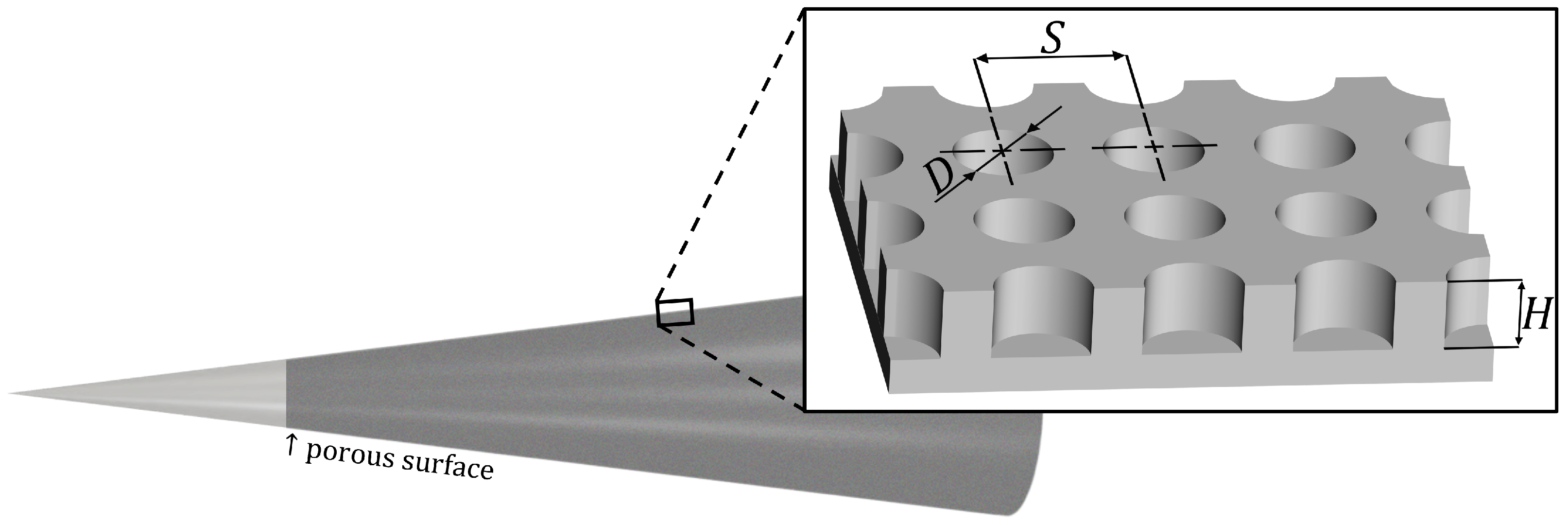
where ρ w is the air density at the wall, c w is the speed of sound at the wall, H is the pore depth, ϕ is the porosity, and S is the unit cell size. The isothermal wall condition is used with T w = 300 K. The pore parameters of a porous surface are depicted in Figure 2. This study considers uniformly distributed circular pores with a pore diameter D, so that the porosity is ϕ = π D 2 / 4 S 2 . Refer to [36] for a detailed description of the impedance model, including the definition of other parameters in Equation (6).
For a given frequency f and streamwise location x, the system of disturbance equations is solved using the Chebyshev collocation method with 151 collocation points distributed across the wall-normal direction within the domain 0 y 6 δ 99 , where δ 99 denotes the boundary layer thickness. In addition, the QR algorithm is employed to solve the eigenvalue problem over the entire computational domain. Local LST analysis is conducted for frequencies ranging from 100 kHz f 1100 kHz at 112 uniformly distributed streamwise locations within the interval 0.05 m x 0.6 m. The most downstream location x = 0.6 m is chosen based on the practical cone sizes available in hypersonic ground facilities [50,51].
The Mack second mode originates from the synchronization of two discrete modes, S (slow mode) and F (fast mode) [55]. After synchronization, either mode S or F abruptly becomes unstable (normally S), which is then identified as the Mack second mode. In this study, the Mack second mode is determined by tracking the S and F modes in the eigenmode spectra obtained from stability analysis at multiple streamwise locations.
The LST solver developed by Lim et al. [15] is employed in this study. This solver has been previously validated for hypersonic boundary layers on smooth [15,16,56,57,58] and porous [16,49] surfaces. Additional LST analysis is conducted in this study for the sharp cone case from reference [59] to further validate the current LST solver. Figure 3 shows that the current LST identifies the Mack second mode accurately. Reference [59] showed a good agreement between its own LST and direct numerical simulation. This cone case of reference [59] validates the current LST solver for stability analysis on a cone geometry at hypersonic speeds.

2.2. Design of Porous Surfaces

Porous surfaces are designed to maximize the absorption of the Mack second mode, considering a practical fabrication process for a specified coverage ( x = 0.15 to 0.6 m) on the cone surface. By minimizing the magnitude of the reflection | R | of an incident wave, a notable improvement in the absorption performance of porous surfaces can be achieved for the Mack second mode instability [16,40,47,60]. In this study, two different approaches to minimizing | R | are explored in designing porous surfaces. The first design approach follows the method from previous studies [16,47], targeting a specific frequency destabilizing the Mack second mode the most. The second approach aims to minimize | R | in a broad range of frequencies where the Mack second mode is unstable, which is a unique approach distinct from those in the literature. The second approach takes into account other frequencies, which could be unstable due to the application of a porous surface. The first and second approaches yield Porous Surfaces 1 and 2, respectively, in this study.
The porous parameters of Porous Surface 1 are determined through the following optimization problem:
min | R ( D , H , S ) | f
subject to D 80 μ m
50 H 600 μ m
S D + 50 μ m
S λ 10 ,
where f is the frequency of the most unstable Mack second mode and λ is the wavelength, all of which are determined for the flow condition listed in Table 1. An electrochemical etching process [61,62] is taken into consideration for the fabrication constraints (Constraints (8)–(10)) of a porous metal plate, following the ongoing experimental approach [63,64]. This method is planned to be applied in porous surface fabrication for ground tests in hypersonic facilities [50,51]. The etching process requires that the pore diameter should be sufficiently large (Constraint (8)) and the height should be limited as Constraint (9). The pore wall needs to be at least 50 µm thick, i.e., Constraint (10), to maintain a straight pore up to H = 600 µm in the etching process. Furthermore, since the acoustic impedance model is valid under the condition S λ [36], Constraint (11) is imposed to ensure sufficiently small cells and pores. Such tiny pores help to absorb the acoustics-like Mack second mode disturbance. Here, f = 620 kHz.
To design Porous Surface 2, an objective function is formulated as given in Equation (12), and the porous parameters are determined with the optimization problem of Equation (13) for the frequency range f min f f max .
J ( D , H , S ) = f min f max | R ( D , H , S , f ) | d f f max f min .
min J ( D , H , S )
subject to D 80 μ m 50 H 600 μ m S D + 50 μ m S λ ( f max ) 10 .
Here, the same fabrication constraints (Constraints (8)–(11)) as those in the design of Porous Surface 1 are imposed. For Constraint (11), the wavelength λ is calculated at the maximum frequency f max , which corresponds to the shortest wavelength within the frequency range of interest in the design of Porous Surface 2. Here, f min = 430 kHz and f max = 700 kHz.
The optimization process is conducted using a parametric sweep with the following parameter intervals: Δ D = 10 μ m , Δ S = 10 μ m , and Δ H = 50 μ m . The interval for the pore depth Δ H is selected based on the minimum thickness, 50 µm, of a metal plate in the ongoing manufacturing process with electrochemical etching [61,62,63,64]. Multiple plates can be combined to deepen the pore with 50 µm increments up to 600 µm.

3. Results and Discussion

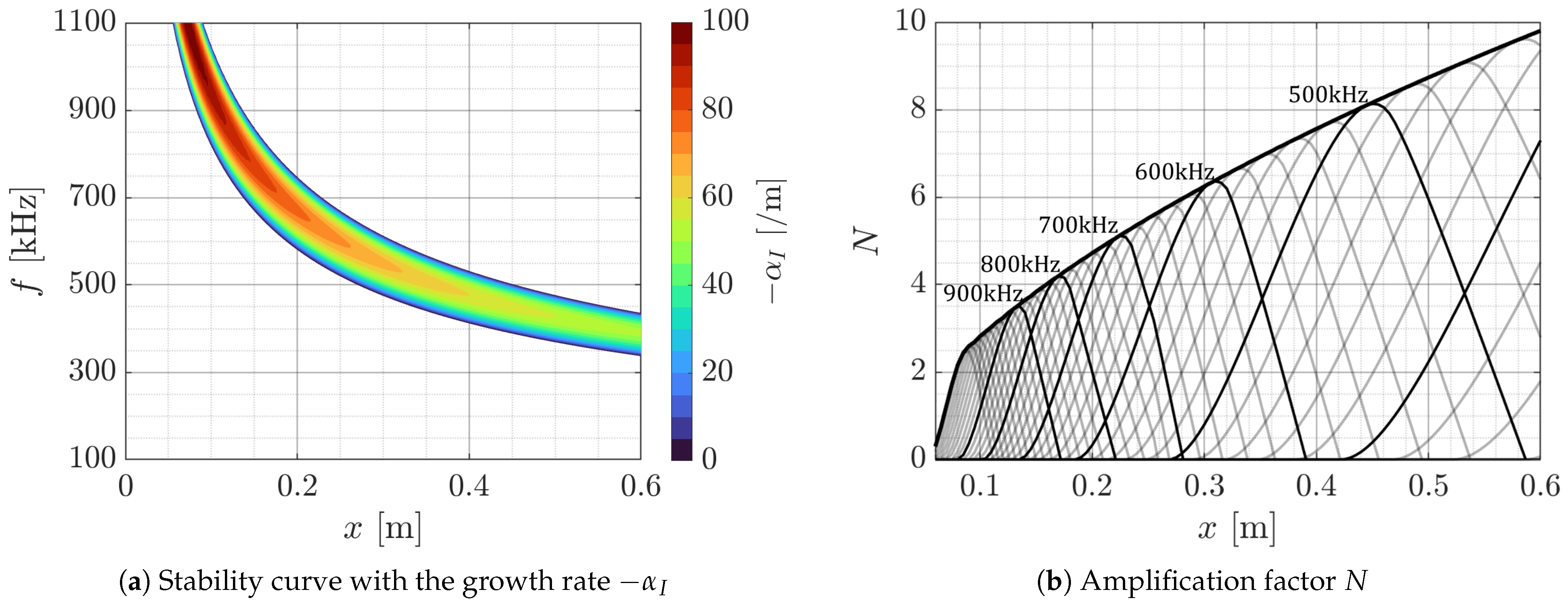
The spatial growth rate of the Mack second mode is determined through the stability analysis using LST to identify the frequency range of the unstable Mack 2nd mode. Figure 4 illustrates the growth rate α I and the amplification factor N for the cone with a smooth surface over the frequency range 100 f 1100 kHz. The integration of α I over a streamwise distance gives N, as expressed in Equation (14).
N ( x , f ) = x 0 x α I d x ,
where x 0 is the initial point at the onset of instability (i.e., branch I of the stability curve). The transition onset location x t r and the corresponding factor N t r depend on the disturbance level in the freestream; various flight conditions and hypersonic ground facilities yield a wide range of N t r [65,66]. In this study, the transition onset factor N t r is obtained from hypersonic ground experiments conducted in both quiet and conventional (relatively noisy) facilities [67,68,69,70]. The frequency of the most unstable Mack second mode is f = 620 kHz with the transition factor N t r = 6 , which falls within the typical N factor range for a noisy hypersonic tunnel. Porous Surface 1 is obtained with the specific frequency f = 620 kHz to stabilize the target-frequency Mack second mode. A wide range of 5 N t r 10 is used for Porous Surface 2 with the intention of stabilizing the disturbances in the frequency range 430 f 700 kHz. The range 5 N t r 10 is related to the flow condition of 2 × 10 6 R e , 1 m 10 7 and 6 M 10 in conventional and quiet hypersonic tunnels [65,68].
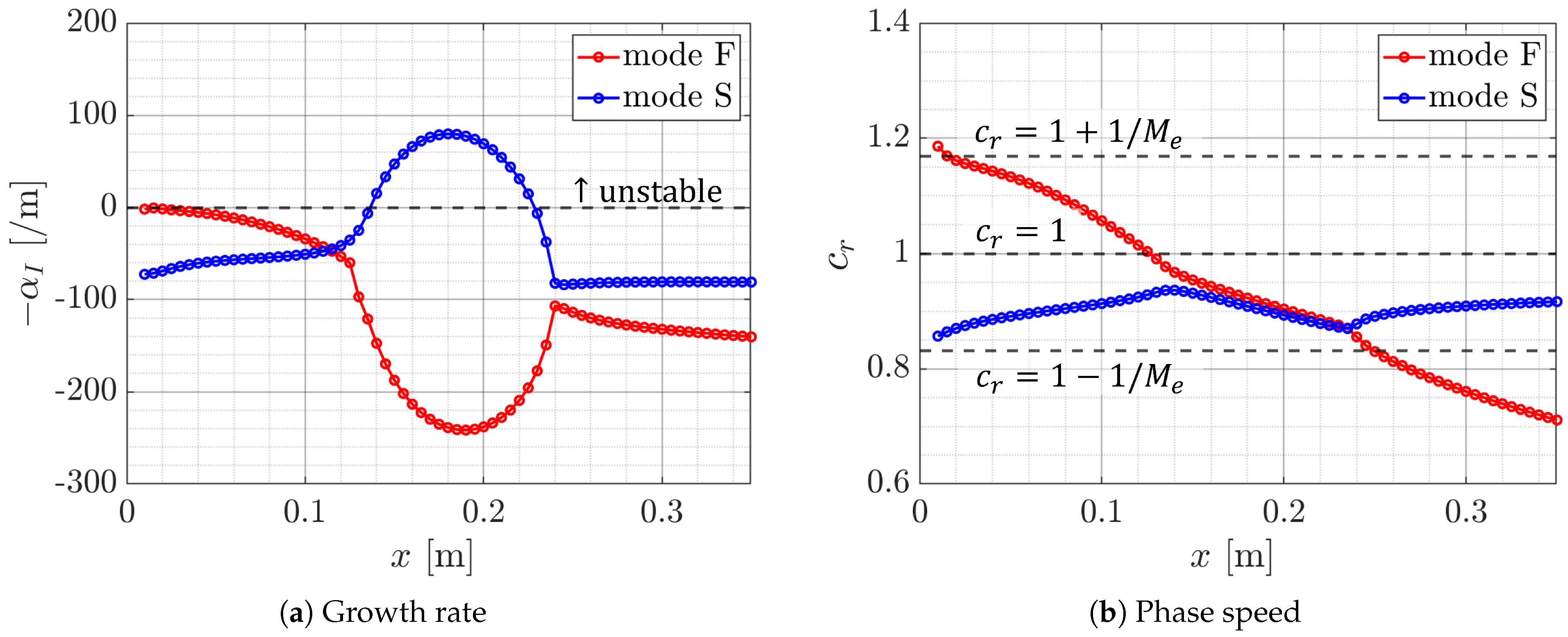
The Mack second mode corresponds to an instability that occurs when either mode S (slow mode) or F (fast mode) becomes unstable due to synchronization, which arises when their phase speeds become very similar [55,71]. To effectively stabilize the Mack second mode, porous surfaces are installed downstream of the synchronization point between modes S and F [37]. Since synchronization at higher frequencies occurs more upstream [71], f = 700 kHz (i.e., the maximum of the target range 430 f 700 kHz) is chosen to identify the synchronization point. Figure 5 illustrates the spatial growth rate α I and the phase speed c r of modes S and F of f = 700 kHz. The growth rate of mode S rapidly increases after x = 0.13 m (this instability is related to the Mack second mode), where the phase speeds of modes S and F are very close to each other. The synchronization between modes S and F of f = 620 kHz occurs in a similar streamwise region. This frequency corresponds to the most unstable Mack second mode in this study. Therefore, Porous Surfaces 1 and 2 are applied from x = 0.15 m to the cone base at x = 0.6 m to effectively suppress the Mack second mode.
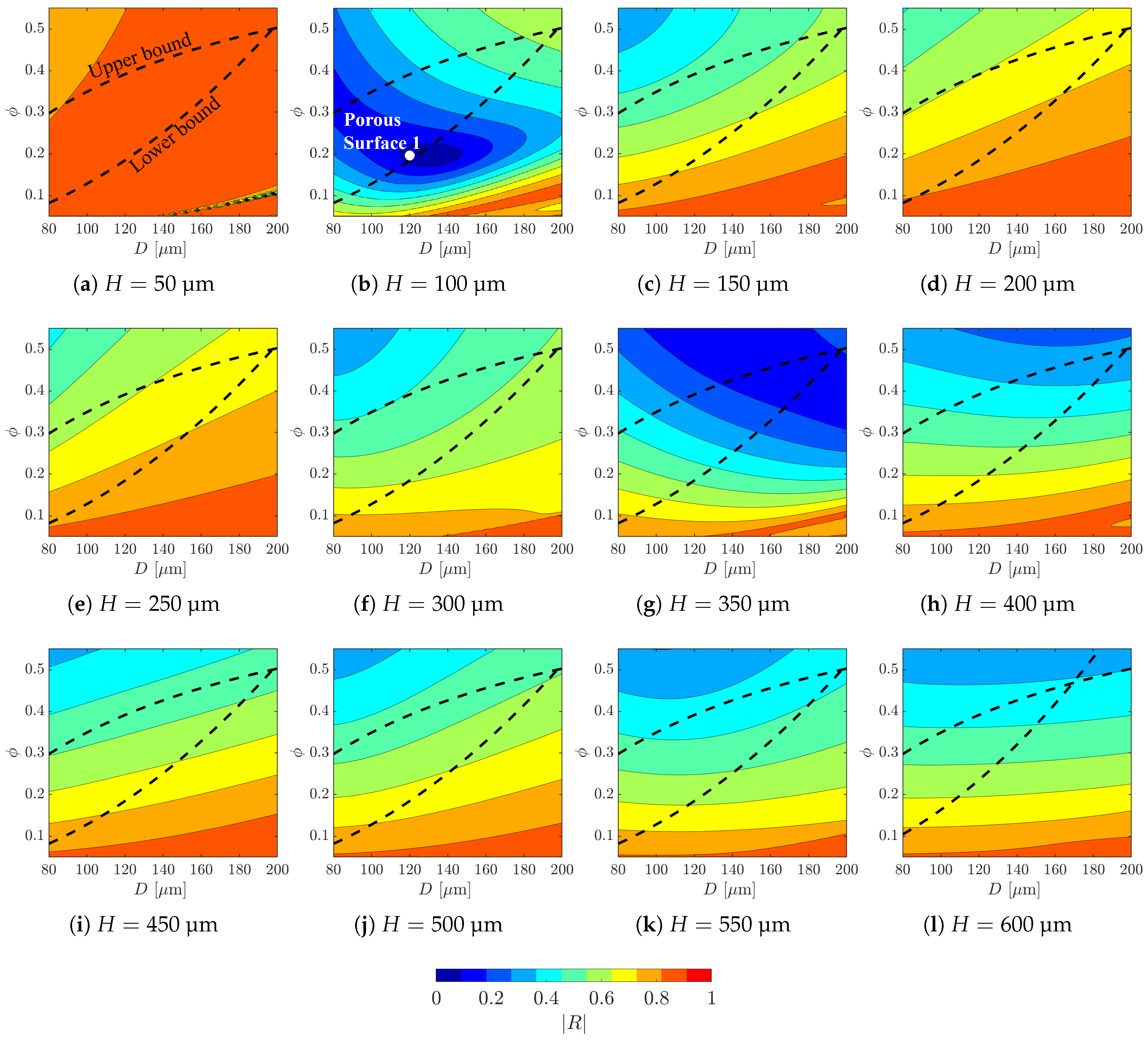
Porous Surface 1 is designed to minimize the reflection coefficient | R | at the target frequency f = 620 kHz of the Mack second mode. Figure 6 illustrates the parameter map for all the pore depths H considered in the current design. The upper and lower bounds in the parameter map (indicated by dashed lines) correspond to the design constraints (Constraints (10) and (11)). Within the current parametric domain, | R | exhibits a non-monotonic trend with respect to H. The minimum absorption | R | is expected to be | R | min = 0.07 with the relatively shallow depth H = 100 µm, indicated with the white dot in Figure 6. For deeper pores, | R | can be comparable, such as | R | min = 0.14 for H = 350 µm. Shallower pores are more convenient in the electrochemical etching process [61,62,63,64]. Therefore, Porous Surface 1 is chosen for the minimum | R | point with H = 100 µm. Interestingly, for the H = 100 µm case, the low reflection coefficient | R | is associated with slightly low porosity ϕ = 0.20 , in contrast to other H cases where higher porosity tends to yield lower | R | . Low | R | at small ϕ could be attributed to the acoustic phase cancellation effect [60]. Zhao et al. [72] also noticed low | R | 0.1 with small ϕ 0.2 . Note that extremely shallow depth, H = 50 µm, yields almost no significant change in | R | . Deeper depth, H 450 µm, yields a similar | R | distribution, which is qualitatively similar to the previous studies [32,34,35,60], where the stabilization performance of the porous surface is less sensitive to H if H is sufficiently larger than a critical value (here, the critical H is H 250 µm [35]). It should be emphasized that the current manufacturing constraints limit the available porosity ϕ 0.5 .
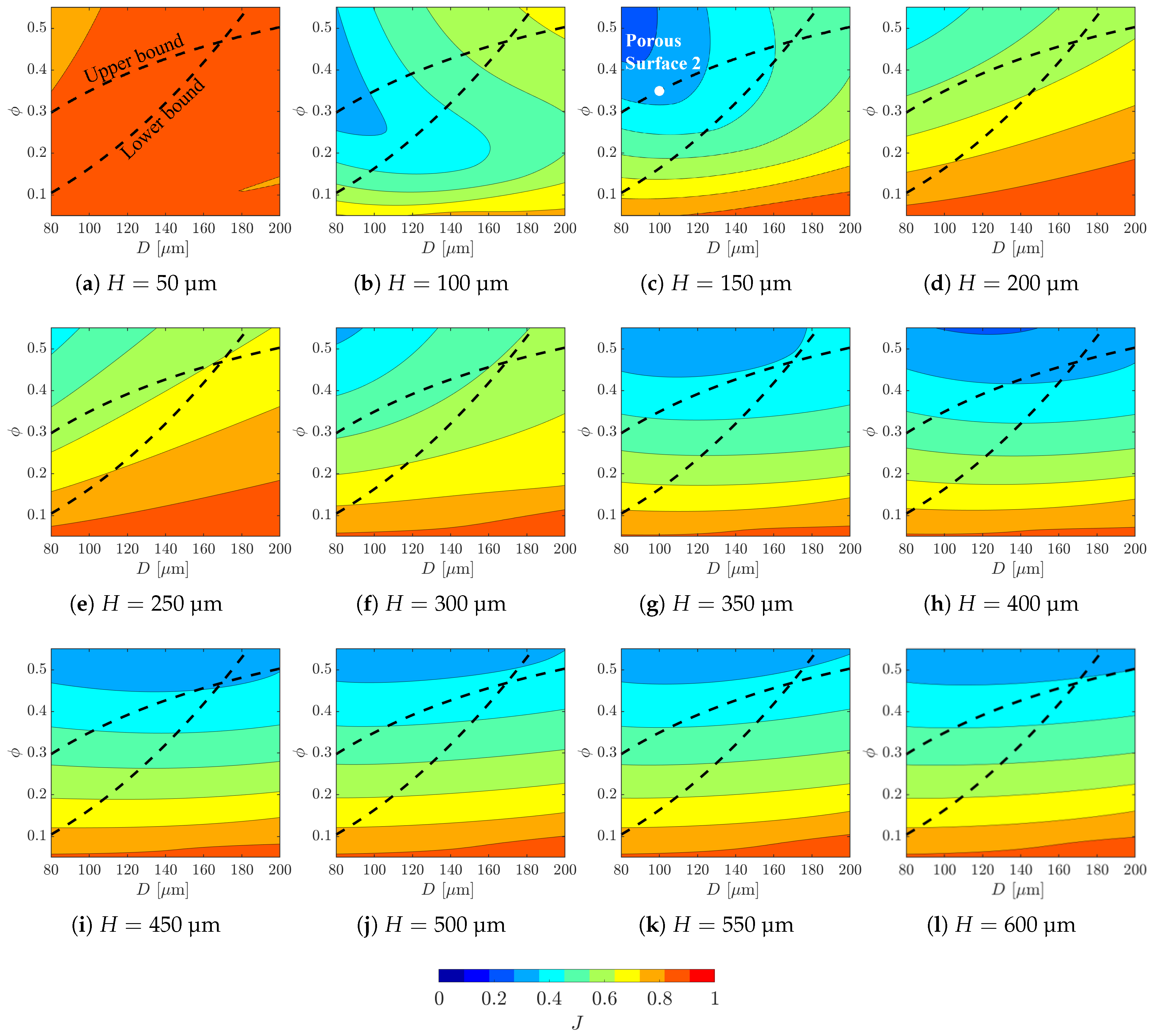
Porous Surface 2 is designed to suppress the Mack second mode over a wide frequency range of f = 430 –700 kHz, by minimizing the objective function J (Equation (12)). Figure 7 shows the design point for Porous Surface 2 in the parameter maps with the variation of H. Since the highest frequency, f = 700 kHz, yields the smallest λ , the lower bound in the design process for Porous Surface 2 is determined based on this frequency. The minimum J = 0.363 for Porous Surface 2 is obtained with the pore depth H = 150 µm and ϕ = 0.35 , as indicated with the white dot. Slightly larger J is obtained in other pore depth cases: J = 0.364 with H = 100 µm and ϕ = 0.30 , and J = 0.371 with H = 400 µm and ϕ = 0.46 . Interestingly, the average absorption property J of the porous surface is less sensitive to H if H 350 µm. This is consistent with minimizing sensitivity in H reported in previous studies on a specific frequency [32,34,35,60] for sufficiently deep pores.
It should be emphasized that the current two design points (Porous Surfaces 1 and 2) are not the global minimum of the optimization process. Realistic design constraints with the valid criterion of the impedance model determine the optimal porous surface. The current study indicates that porous surface design needs to take into account a practical fabrication process for porous surfaces.
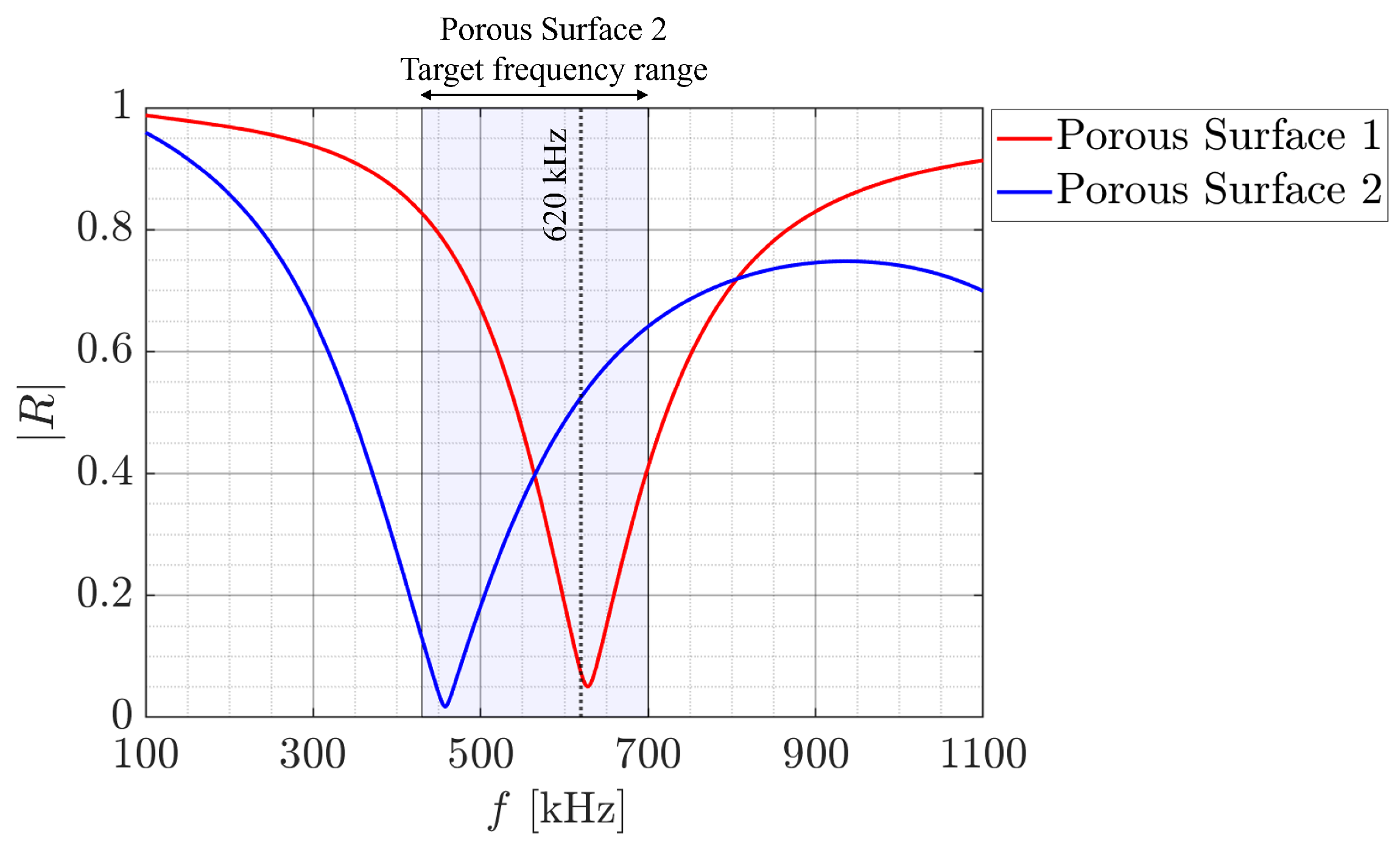
The geometric parameters of Porous Surfaces 1 and 2 are listed in Table 2. The two porous surfaces have similar diameters D with only a difference of 20 µm. Porous Surface 2 contains deeper pores (higher H) with higher ϕ (i.e., denser distribution with shorter S), compared to Porous Surface 1. The depth-to-diameter ratio ( A r = H / D ) is A r = 0.83 for Porous Surface 1 and A r = 1.5 for Porous Surface 2, both of which fall within the range typically considered as shallow pores. Such shallow pores have been analyzed and recommended due to their advantage in fabrication [2,34,73]. The total number of pores within the porous wall coverage ( x = 0.15 to 0.6 m) on the cone is approximately 2.2 million for Porous Surface 1 and 5.7 million for Porous Surface 2. The reflection coefficients | R | of Porous Surfaces 1 and 2 are compared in Figure 8 for the frequency range of interest. The reflection | R | for Porous Surface 1 is the smallest near the target frequency f = 620 kHz. In contrast, Porous Surface 2 exhibits the lowest | R | around f = 460 kHz and higher | R | than Porous Surface 1 for the range of 560 < f < 810 kHz. The averaged | R | in the frequency range 430 f 700 kHz is | R | avg = 0.36 for Porous Surface 2, which is lower than | R | avg = 0.44 for Porous Surface 1.
Linear stability analysis is pursued to investigate how the Mack 2nd mode with various frequencies grows on these two porous surfaces. Note that the phase of the complex reflection coefficient R can also affect the stabilization effect of the porous surface [60]. Since the current porous surfaces are designed with the magnitude | R | , LST analysis with the impedance model (Equations (5) and (6)) is needed to incorporate the effect of the R phase.
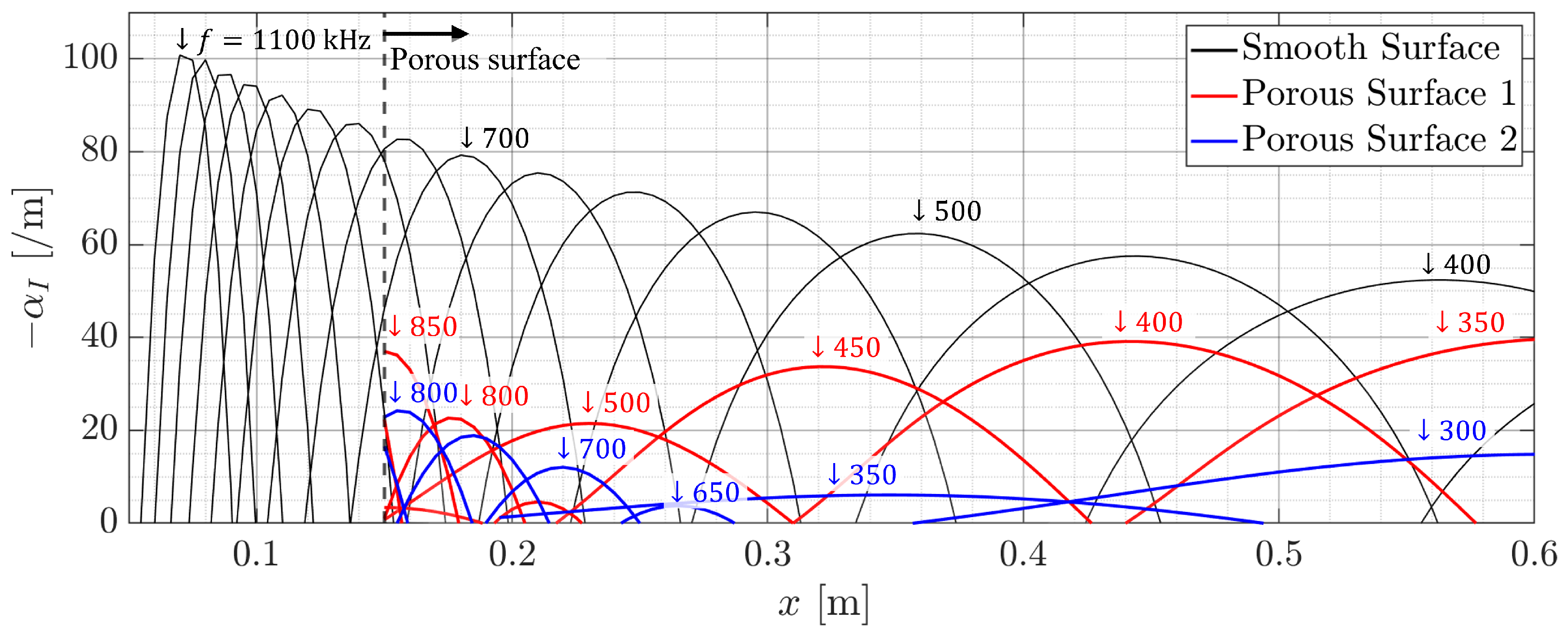
Figure 9 illustrates the spatial growth rate, α I , obtained from the LST analysis for the cone with the two porous surfaces over the frequency range f = 100 1100 kHz. For effective suppression performance, both 1 and Porous Surface 2 start at x = 0.15 m, which is near the synchronization point (Figure 5). Porous Surface 1 stabilizes instabilities within the range 560 f 740 kHz. Even within the remaining unstable region, the growth rate α I is suppressed compared to that of the smooth surface, as shown in Figure 4a. Porous Surface 2 exhibits even stronger stabilization performance. Instabilities in the range 430 f 630 kHz are stabilized, and the growth rate α I in the unstable region is significantly lower than that of both the smooth surface and Porous Surface 1. Overall, Porous Surface 2 demonstrates superior stabilization performance compared to Porous Surface 1.
The spatial growth rate of the unstable Mack second mode is further examined, as shown in Figure 10. The growth rate α I is plotted over the frequency range of f = 100–1100 kHz with a frequency interval of Δ f = 50 kHz. Porous Surface 2 effectively suppresses the growth of the unstable mode across the frequency, maintaining a minimum absorption performance of approximately 70%. In contrast, Porous Surface 1 exhibits highly frequency-dependent performance, with suppression as low as 25% in the least effective case. Porous Surface 2 demonstrates consistent absorption performance over the broad frequency range.
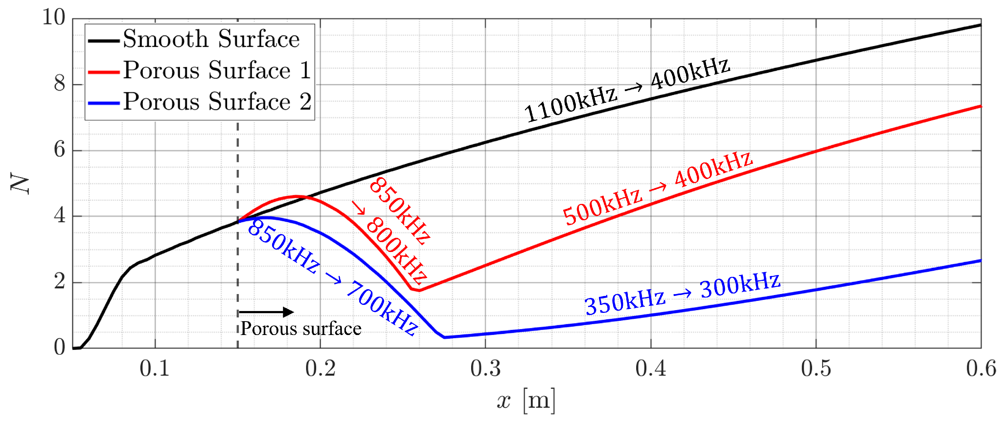
The amplification factor N is calculated from the growth rates over the two porous surfaces and compared with that of the smooth surface, as shown in Figure 11. The envelope of the N factor corresponding to each surface is plotted with the relevant frequency variation over each data curve. The N envelope represents the maximum N at each streamwise location. The N envelope for the smooth surface increases as the Mack 2nd mode convects downstream. The corresponding frequency for the maximum N (i.e., the most amplified mode frequency) shifts to a lower frequency around f 400 kHz downstream. On Porous Surfaces 1 and 2, the maximum N is reduced from the starting point of the porous surface ( x = 0.15 m) and grows again in a relatively low frequency region. The amplification factor N exceeds 6 after x = 0.5 m on Porous Surface 1. Therefore, it is expected that the turbulent transition still occurs on the current cone surface, even with the expected delay of the transition. In contrast, Porous Surface 2 effectively suppresses the Mack 2nd mode all the way to the cone base at x = 0.6 m. The amplification factor remains sufficiently low with N 4 throughout the cone surface, suggesting that the transition may not occur, even in a conventional hypersonic facility.

4. Conclusions

An optimal design approach for a uniform porous surface is proposed to suppress the Mack second mode over a broad frequency range. This approach incorporates the requirements of a practical fabrication process as design constraints for porous surfaces. Electrochemical etching is chosen here as the fabrication method because it can puncture millions of pores simultaneously and efficiently. This method is planned to be applied in ground tests conducted in hypersonic facilities [50,51]. In addition, a cone geometry available for these facilities is adopted for analyzing the hypersonic boundary layer. The absorption performance of porous surfaces with respect to the dominant instability, i.e., the Mack second mode, is evaluated using the acoustic impedance model, and its effectiveness is examined in a wide frequency range. The approach is compared with a conventional method focused on a single target frequency of the Mack second mode. Stabilization performance is assessed through linear stability theory with the impedance model.
The effect of pore size and porosity on the absorption performance is estimated with the acoustic impedance model to design porous surfaces. Interestingly, the global minimum identified in the conventional design approach lies outside the current parameter domain due to the fabrication constraints. Therefore, practical manufacturability must be considered in order to design an effective porous surface that can be fabricated.
The current study demonstrates that a uniform porous surface can effectively suppress the Mack second mode over a broad frequency range. Two porous surfaces are designed and compared: Porous Surface 1, designed for the most unstable frequency ( f = 620 kHz), and Porous Surface 2, designed for the broad frequency range ( 430 f 700 kHz). Porous Surface 2 exhibits more effective and consistent stabilization across the frequency, suggesting the potential to maintain laminar flow on the current cone without turbulent transition under the present flow condition.
Overall, this study proposes an efficient and practical methodology for designing porous surfaces. In particular, it considers two critical factors: manufacturing constraints imposed by realistic fabrication processes and the absorption capability of porous surfaces over a wide frequency range associated with the dominant instability, i.e., the Mack second mode. These considerations enhance both the stabilization performance and the manufacturability of the designed porous surfaces. As the present study is based on LST analysis, further investigations are necessary to assess nonlinear interactions among multiple instabilities, including thew potential destabilization of other instabilities. Nonlinear stability analysis or direct numerical simulation could incorporate the nonlinear effect, which remains for a future study. The effect of the first mode on transition also remains to be seen because porous surfaces may destabilize the first mode. In addition, it is important to validate the expected transition delay of the designed porous surfaces in an experiment. A hypersonic ground test is currently planned [50,51], and test data will be analyzed with the current numerical approach. Future extensions of the current design methodology are expected by considering variations in flow conditions (e.g., Mach number, wall temperature, and cone geometry). Taken together, the proposed design approach is expected to aid in selecting optimal porous parameters for effective transition control in hypersonic applications.

Author Contributions

Conceptualization, S.J.; methodology, Y.K., M.J., S.C., D.P. and S.J.; software, Y.K., M.J. and S.C.; validation, Y.K.; formal analysis, Y.K.; investigation, Y.K. and S.J.; resources, S.J.; data curation, Y.K.; writing—original draft preparation, Y.K.; writing—review and editing, S.J., D.P. and M.J.; visualization, Y.K.; supervision, S.J.; project administration, S.J.; funding acquisition, S.J. All authors have read and agreed to the published version of the manuscript.

Funding

This research was supported by the Challengeable Future Defense Technology Research and Development Program through the Agency for Defense Development (ADD) funded by the Defense Acquisition Program Administration (DAPA) in 2022–2025 (No. 915067201).

Data Availability Statement

The data that support the findings of this study are available from the corresponding author upon reasonable request.

Conflicts of Interest

The authors declare no conflicts of interest.

References

  1. Saric, W.S.; Reed, H.L.; Kerschen, E.J. Boundary-layer receptivity to freestream disturbances. Annu. Rev. Fluid Mech. 2002, 34, 291–319. [Google Scholar] [CrossRef]
  2. Fedorov, A. Transition and stability of high-speed boundary layers. Annu. Rev. Fluid Mech. 2011, 43, 79–95. [Google Scholar] [CrossRef]
  3. Zhong, X.; Wang, X. Direct numerical simulation on the receptivity, instability, and transition of hypersonic boundary layers. Annu. Rev. Fluid Mech. 2012, 44, 527–561. [Google Scholar] [CrossRef]
  4. Malik, M.; Zang, T.; Bushnell, D. Boundary Layer Transition in Hypersonic Flows. In Proceedings of the 2nd AIAA International Aerospace Planes Conference, Orlando, FL, USA, 29–31 October 1990. [Google Scholar] [CrossRef]
  5. Reshotko, E. Boundary Layer Instability, Transition and Control. In Proceedings of the 32nd AIAA Aerospace Sciences Meeting and Exhibit, Reno, NV, USA, 10–13 January 1994. [Google Scholar] [CrossRef]
  6. Yin, Y.; Lu, R.; Liu, J.; Huang, Z. Real gas effects on receptivity to roughness in hypersonic swept blunt flat-plate boundary layers. Aerospace 2024, 11, 58. [Google Scholar] [CrossRef]
  7. Mack, L.M. Boundary-layer linear stability theory. In Special Course on Stability and Transition of Laminar Flow; AGARD Report 709; Advisory Group for Aerospace Research and Development (AGARD): Neuilly sur Seine, France, 1984. [Google Scholar]
  8. Yang, H.s.; Liang, H.; Guo, S.g.; Tang, M.x.; Zhang, C.b.; Wu, Y.; Li, Y.h. Research progress of hypersonic boundary layer transition control experiments. Adv. Aerodyn. 2022, 4, 18. [Google Scholar] [CrossRef]
  9. Zhao, R.; Wen, C.; Zhou, Y.; Tu, G.; Lei, J. Review of acoustic metasurfaces for hypersonic boundary layer stabilization. Prog. Aerosp. Sci. 2022, 130, 100808. [Google Scholar] [CrossRef]
  10. Kimmel, R. Aspects of Hypersonic Boundary-Layer Transition Control. In Proceedings of the 41st AIAA Aerospace Sciences Meeting and Exhibit, Reno, NV, USA, 6–9 January 2003. [Google Scholar] [CrossRef]
  11. Fedorov, A.V. Prediction and control of laminar-turbulent transition in high-speed boundary-layer flows. Procedia IUTAM 2015, 14, 3–14. [Google Scholar] [CrossRef]
  12. Rasheed, A.; Hornung, H.G.; Fedorov, A.V.; Malmuth, N.D. Experiments on passive hypervelocity boundary-layer control using an ultrasonically absorptive surface. AIAA J. 2002, 40, 481–489. [Google Scholar] [CrossRef]
  13. Fedorov, A.; Shiplyuk, A.; Maslov, A.; Burov, E.; Malmuth, N. Stabilization of a hypersonic boundary layer using an ultrasonically absorptive coating. J. Fluid Mech. 2003, 479, 99–124; Corrigendum in J. Fluid Mech. 2015, 769, 725–728. [Google Scholar] [CrossRef]
  14. Lukashevich, S.; Morozov, S.; Shiplyuk, A. Passive porous coating effect on a hypersonic boundary layer on a sharp cone at small angle of attack. Exp. Fluids 2018, 59, 130. [Google Scholar] [CrossRef]
  15. Lim, J.; Kim, M.; Park, J.; Kim, T.; Jee, S.; Park, D. Simulation of hypersonic boundary layer on porous surfaces using OpenFOAM. Comput. Fluids 2022, 240, 105437. [Google Scholar] [CrossRef]
  16. Lim, J.; Kim, M.; Bae, H.; Lin, R.S.; Jee, S. Turbulent transition control using porous surfaces in hypersonic boundary layer. Int. J. Aeronaut. Space Sci. 2023, 24, 972–984. [Google Scholar] [CrossRef]
  17. Running, C.L.; Bemis, B.L.; Hill, J.L.; Borg, M.P.; Redmond, J.J.; Jantze, K.; Scalo, C. Attenuation of hypersonic second-mode boundary-layer instability with an ultrasonically absorptive silicon-carbide foam. Exp. Fluids 2023, 64, 79. [Google Scholar] [CrossRef]
  18. Holloway, P.F.; Sterrett, J.R. Effect of Controlled Surface Roughness on Boundary-Layer Transition and Heat Transfer at Mach Numbers of 4.8 and 6.0; Technical Report NASA-TN-D-2054; NASA Langley Research Center: Hampton, VA, USA, 1964. [Google Scholar]
  19. Duan, L.; Wang, X.; Zhong, X. Stabilization of a Mach 5.92 boundary layer by two-dimensional finite-height roughness. AIAA J. 2012, 51, 266–270. [Google Scholar] [CrossRef]
  20. Fong, K.D.; Wang, X.; Huang, Y.; Zhong, X.; McKiernan, G.R.; Fisher, R.A.; Schneider, S.P. Second mode suppression in hypersonic boundary layer by roughness: Design and experiments. AIAA J. 2015, 53, 3138–3144. [Google Scholar] [CrossRef]
  21. Fedorov, A.; Soudakov, V.; Egorov, I.; Sidorenko, A.; Gromyko, Y.; Bountin, D.; Polivanov, P.; Maslov, A. High-speed boundary-layer stability on a cone with localized wall heating or cooling. AIAA J. 2015, 53, 2512–2524. [Google Scholar] [CrossRef]
  22. Zhao, R.; Wen, C.; Tian, X.; Long, T.; Yuan, W. Numerical simulation of local wall heating and cooling effect on the stability of a hypersonic boundary layer. Int. J. Heat Mass Transf. 2018, 121, 986–998. [Google Scholar] [CrossRef]
  23. Oz, F.; Goebel, T.E.; Jewell, J.S.; Kara, K. Local wall cooling effects on hypersonic boundary-layer stability. J. Spacecr. Rocket. 2023, 60, 412–426. [Google Scholar] [CrossRef]
  24. Leyva, I.; Laurence, S.; Beierholm, A.; Hornung, H.; Wagnild, R.; Candler, G. Transition Delay in Hypervelocity Boundary Layers by Means of CO2/Acoustic Instability Interactions. In Proceedings of the 47th AIAA Aerospace Sciences Meeting including the New Horizons Forum and Aerospace Exposition, Orlando, FL, USA, 5–8 January 2009. [Google Scholar] [CrossRef]
  25. Miró, F.M.; Pinna, F. Injection-gas-composition effects on hypersonic boundary-layer transition. J. Fluid Mech. 2020, 890, R4. [Google Scholar] [CrossRef]
  26. Shang, J.; Surzhikov, S.; Kimmel, R.; Gaitonde, D.; Menart, J.; Hayes, J. Mechanisms of plasma actuators for hypersonic flow control. Prog. Aerosp. Sci. 2005, 41, 642–668. [Google Scholar] [CrossRef]
  27. Yang, B.; Yang, H.; Zhao, N.; Liang, H.; Su, Z.; Zhang, D. Experimental study on hypersonic double-wedge induced flow based on plasma active actuation array. Aerospace 2024, 11, 60. [Google Scholar] [CrossRef]
  28. Liu, X.; Luo, Z.; Liu, Q.; Cheng, P.; Zhou, Y. Numerical investigation of hypersonic flat-plate boundary layer transition subjected to bi-frequency synthetic jet. Aerospace 2023, 10, 766. [Google Scholar] [CrossRef]
  29. Zhuang, G.H.; Wan, Z.H.; Ye, C.C.; Luo, Z.B.; Liu, N.S.; Sun, D.J.; Lu, X.Y. Active transition control by synthetic jets in a hypersonic boundary layer. Phys. Fluids 2023, 35, 034112. [Google Scholar] [CrossRef]
  30. Liu, J.; Xu, M.; Zhang, R.; Zhang, X.; Xi, W. Progress of porous/lattice structures applied in thermal management technology of aerospace applications. Aerospace 2022, 9, 827. [Google Scholar] [CrossRef]
  31. Malmuth, N.; Fedorov, A.; Shalaev, V.; Cole, J.; Hites, M.; Williams, D.; Khokhlov, A. Problems in High Speed Flow Prediction Relevant to Control. In Proceedings of the 2nd AIAA, Theoretical Fluid Mechanics Meeting, Albuquerque, NM, USA, 15–18 June 1998. [Google Scholar] [CrossRef]
  32. Fedorov, A.V.; Malmuth, N.D.; Rasheed, A.; Hornung, H.G. Stabilization of hypersonic boundary layers by porous coatings. AIAA J. 2001, 39, 605–610. [Google Scholar] [CrossRef]
  33. Fedorov, A.; Malmuth, N. Parametric Studies of Hypersonic Laminar Flow Control Using a Porous Coating of Regular Microstructure. In Proceedings of the 46th AIAA Aerospace Sciences Meeting and Exhibit, Reno, NV, USA, 7–10 January 2008. [Google Scholar] [CrossRef]
  34. Sandham, N.D.; Lüdeke, H. Numerical study of Mach 6 boundary-layer stabilization by means of a porous surface. AIAA J. 2009, 47, 2243–2252. [Google Scholar] [CrossRef]
  35. Lukashevich, S.V.; Maslov, A.A.; Shiplyuk, A.N.; Fedorov, A.V.; Soudakov, V.G. Stabilization of high-speed boundary layer using porous coatings of various thicknesses. AIAA J. 2012, 50, 1897–1904. [Google Scholar] [CrossRef]
  36. Zhao, R.; Zhang, X.X.; Wen, C.Y. Theoretical modeling of porous coatings with simple microstructures for hypersonic boundary-layer stabilization. AIAA J. 2020, 58, 981–986. [Google Scholar] [CrossRef]
  37. Wang, X.; Zhong, X. The stabilization of a hypersonic boundary layer using local sections of porous coating. Phys. Fluids 2012, 24, 034105. [Google Scholar] [CrossRef]
  38. Lukashevich, S.V.; Morozov, S.O.; Shiplyuk, A.N. Experimental study of the effect of a passive porous coating on disturbances in a hypersonic boundary layer. 1. Effect of the porous coating length. J. Appl. Mech. Tech. Phys. 2013, 54, 572–577. [Google Scholar] [CrossRef]
  39. Lukashevich, S.V.; Morozov, S.O.; Shiplyuk, A.N. Experimental study of the effect of a passive porous coating on disturbances in a hypersonic boundary layer 2. Effect of the porous coating location. J. Appl. Mech. Tech. Phys. 2016, 57, 873–878. [Google Scholar] [CrossRef]
  40. Brès, G.; Inkman, M.; Colonius, T.; Fedorov, A. Alternate Designs of Ultrasonic Absorptive Coatings for Hypersonic Boundary Layer Control. In Proceedings of the 39th AIAA Fluid Dynamics Conference, San Antonio, TX, USA, 22–25 June 2009. [Google Scholar] [CrossRef]
  41. Brès, G.A.; Colonius, T.; Fedorov, A.V. Acoustic properties of porous coatings for hypersonic boundary-layer control. AIAA J. 2010, 48, 267–274. [Google Scholar] [CrossRef]
  42. Tian, X.; Zhao, R.; Long, T.; Wen, C.Y. Reverse design of ultrasonic absorptive coating for the stabilization of Mack modes. AIAA J. 2019, 57, 2264–2269. [Google Scholar] [CrossRef]
  43. Zhao, R.; Fan, Y.; Liu, X.; Wen, C. Stabilization effect of acoustic metasurfaces on broadband disturbances in a Mach 6 boundary-layer flow. Phys. Fluids 2022, 34, 121706. [Google Scholar] [CrossRef]
  44. Maslov, A.; Shiplyuk, A.; Sidorenko, A.; Polivanov, P.; Fedorov, A.; Kozlov, V.; Malmuth, N. Hypersonic Laminar Flow Control Using a Porous Coating of Random Microstructure. In Proceedings of the 44th AIAA Aerospace Sciences Meeting and Exhibit, Reno, NV, USA, 9–12 January 2006. [Google Scholar] [CrossRef]
  45. Egorov, I.; Fedorov, A.; Soudakov, V. Receptivity of a hypersonic boundary layer over a flat plate with a porous coating. J. Fluid Mech. 2008, 601, 165–187. [Google Scholar] [CrossRef]
  46. Fedorov, A. Temporal Stability of Hypersonic Boundary Layer on Porous Wall: Comparison of Theory with DNS. In Proceedings of the 48th AIAA Aerospace Sciences Meeting Including the New Horizons Forum and Aerospace Exposition, Orlando, FL, USA, 4–7 January 2010. [Google Scholar] [CrossRef]
  47. Zhao, R.; Wen, C.; Long, T.; Tian, X.; Zhou, L.; Wu, Y. Spatial direct numerical simulation of the hypersonic boundary-layer stabilization using porous coatings. AIAA J. 2019, 57, 5061–5065. [Google Scholar] [CrossRef]
  48. Xu, J.; Liu, J.; Mughal, S.; Yu, P.; Bai, J. Secondary instability of Mack mode disturbances in hypersonic boundary layers over micro-porous surface. Phys. Fluids 2020, 32, 044105. [Google Scholar] [CrossRef]
  49. Lim, J.; Kim, M.; Jeong, M.; Cho, S.; Jee, S. Computational Study on the Stability of Hypersonic Boundary Layer on a Porous Surface. In Proceedings of the AIAA SCITECH 2024 Forum, Orlando, FL, USA, 8–12 January 2024. [Google Scholar] [CrossRef]
  50. Kim, J.; Kim, J.; Hur, J.; Lee, B.J. Nozzle flow characterization of the SNU hypersonic shock tunnel. Int. J. Aeronaut. Space Sci. 2024, 26, 953–962. [Google Scholar] [CrossRef]
  51. Kim, D.M.; Lee, H.J. Experimental Visualization of Hypersonic Boundary Layer Transition. In Proceedings of the AIAA SCITECH 2025 Forum, Orlando, FL, USA, 6–10 January 2025. [Google Scholar] [CrossRef]
  52. White, F.M. Laminar boundary layers. In Viscous Fluid Flow, 3rd ed.; McGraw-Hill: New York, NY, USA, 2006; Chapter 4.10.2; pp. 293–294. [Google Scholar]
  53. Malik, M.R. Numerical methods for hypersonic boundary layer stability. J. Comput. Phys. 1990, 86, 376–413. [Google Scholar] [CrossRef]
  54. Park, D. Linear and Non-Linear Stability Analysis of Boundary Layers over a Hump by Using PSE. Ph.D. Thesis, Korea Advanced Institute of Science and Technology, Daejeon, Republic of Korea, 2013. [Google Scholar]
  55. Fedorov, A.; Tumin, A. High-speed boundary-layer instability: Old terminology and a new framework. AIAA J. 2011, 49, 1647–1657. [Google Scholar] [CrossRef]
  56. Bae, H.; Lim, J.; Kim, M.; Jee, S. Direct-numerical simulation with the stability theory for turbulent transition in hypersonic boundary layer. Int. J. Aeronaut. Space Sci. 2023, 24, 1004–1014. [Google Scholar] [CrossRef]
  57. Lim, J.; Jeong, M.; Kim, M.; Jee, S. Eddy-resolving simulation coupled with stability analysis for turbulent transition in compressible boundary layer. Flow Turbul. Combust. 2024, 115, 79–104. [Google Scholar] [CrossRef]
  58. Jeong, M.; Cho, S.; Kim, Y.; Park, J.; Jee, S. High-fidelity simulation of laminar-to-turbulent transition in hypersonic boundary layer on a sharp cone. Phys. Fluids 2025, 37, 034120. [Google Scholar] [CrossRef]
  59. Sivasubramanian, J.; Fasel, H.F. Direct numerical simulation of transition in a sharp cone boundary layer at Mach 6: Fundamental breakdown. J. Fluid Mech. 2015, 768, 175–218. [Google Scholar] [CrossRef]
  60. Brès, G.A.; Inkman, M.; Colonius, T.; Fedorov, A.V. Second-mode attenuation and cancellation by porous coatings in a high-speed boundary layer. J. Fluid Mech. 2013, 726, 312–337. [Google Scholar] [CrossRef]
  61. Köhler, M. Wet-chemical etching methods. In Etching in Microsystem Technology; WILEY-VCH: Weinheim, Germany, 1999; Chapter 3; pp. 73, 79, 100–101. [Google Scholar]
  62. Patel, D.; Jain, V.; Ramkumar, J. Micro texturing on metallic surfaces: State of the art. Proc. Inst. Mech. Eng. Part B J. Eng. Manuf. 2018, 232, 941–964. [Google Scholar] [CrossRef]
  63. Lee, J.; Hong, S. A Study on the Fabrication Process of Porous Surface and Experimental Model for Reducing Aerodynamic Heating of Hypersonic Boundary Layer Flow. In Proceedings of the Annual Conference of the Korean Society of Mechanical Engineering (KSME), Jeju Island, Republic of Korea, 6–9 November 2024. [Google Scholar]
  64. Jung, T.; Lee, J. A Study on the Design Process of Manufacturable Porous Microstructure for Reducing Aerodynamic Heating of Hypersonic Boundary Layer Flow. In Proceedings of the Annual Space Conference of the Korean Society for Aeronautical and Space Sciences (KSAS), Jeju, Republic of Korea, 19–21 April 2023. [Google Scholar]
  65. Marineau, E.C.; Grossir, G.; Wagner, A.; Leinemann, M.; Radespiel, R.; Tanno, H.; Chynoweth, B.C.; Schneider, S.P.; Wagnild, R.M.; Casper, K.M. Analysis of second-mode amplitudes on sharp cones in hypersonic wind tunnels. J. Spacecr. Rocket. 2018, 56, 307–318. [Google Scholar] [CrossRef]
  66. Ingen, J.V. The eN Method for Transition Prediction. Historical Review of Work at TU Delft. In Proceedings of the 38th AIAA Fluid Dynamics Conference and Exhibit, Seattle, WA, USA, 23–26 June 2008. [Google Scholar] [CrossRef]
  67. Schneider, S.P. Effects of high-speed tunnel noise on laminar-turbulent transition. J. Spacecr. Rocket. 2001, 38, 323–333. [Google Scholar] [CrossRef]
  68. Alba, C.; Casper, K.; Beresh, S.; Schneider, S. Comparison of Experimentally Measured and Computed Second-Mode Disturbances in Hypersonic Boundary-Layers. In Proceedings of the 48th AIAA Aerospace Sciences Meeting Including the New Horizons Forum and Aerospace Exposition, Orlando, FL, USA, 4–7 January 2010. [Google Scholar] [CrossRef]
  69. Berridge, D.; Casper, K.; Rufer, S.; Alba, C.; Lewis, D.; Beresh, S.; Schneider, S. Measurements and Computations of Second-Mode Instability Waves in Several Hypersonic Wind Tunnels. In Proceedings of the 40th AIAA Fluid Dynamics Conference and Exhibit, Chicago, IL, USA, 28 June–1 July 2010. [Google Scholar] [CrossRef]
  70. Juliano, T.J.; Kimmel, R.L.; Willems, S.; Guelhan, A.; Wagnild, R. HIFiRE-1 Boundary-Layer Transition: Ground Test Results and Stability Analysis. In Proceedings of the 53rd AIAA Aerospace Sciences Meeting, Kissimmee, FL, USA, 5–9 January 2015. [Google Scholar] [CrossRef]
  71. Fedorov, A.V.; Khokhlov, A.P. Prehistory of instability in a hypersonic boundary layer. Theor. Comput. Fluid Dyn. 2001, 14, 359–375. [Google Scholar] [CrossRef]
  72. Zhao, R.; Liu, T.; Wen, C.Y.; Zhu, J.; Cheng, L. Theoretical modeling and optimization of porous coating for hypersonic laminar flow control. AIAA J. 2018, 56, 2942–2946. [Google Scholar] [CrossRef]
  73. Zhao, R.; Liu, T.; Wen, C.y.; Zhu, J.; Cheng, L. Impedance-near-zero acoustic metasurface for hypersonic boundary-layer flow stabilization. Phys. Rev. Appl. 2019, 11, 044015. [Google Scholar] [CrossRef]
Figure 1. Flow condition of the current study for the hypersonic flow over a sharp 7-degree half-angle cone.
Aerospace 12 00518 g001
Figure 2. Schematic diagram of porous surface with uniformly distributed circular pores.
Aerospace 12 00518 g002
Figure 3. Comparison of the Mack second mode between the current LST and reference [59] for the hypersonic boundary layer on the sharp cone at Mach 6.
Aerospace 12 00518 g003
Figure 4. LST analysis of hypersonic boundary layer on the sharp cone with the frequency range 100 f 1100 kHz.
Aerospace 12 00518 g004
Figure 5. Spatial growth rate α I and phase speed c r of modes S and F of f = 700 kHz.
Aerospace 12 00518 g005
Figure 6. Parameter map to determine Porous Surface 1 with the reflection magnitude | R | , over a pore depth range of 50 H 600 µm with an interval of Δ H = 50 μ m . Upper and lower bounds indicate the design constraints π ( D / 2 ) 2 / ( λ / 10 ) 2 ϕ π ( D / 2 ) 2 / ( D + 50 μ m ) 2 with ϕ = π D 2 / 4 S 2 (Constraints (10) and (11)) where λ = λ ( f = 620 kHz ) 2500 µm.
Aerospace 12 00518 g006
Figure 7. Parameter map to determine Porous Surface 2 with the objective function J (Equation (12)), over a pore depth range of 50 H 600 µm with an interval of Δ H = 50 μ m . Upper and lower bounds indicate the design constraints π ( D / 2 ) 2 / ( λ / 10 ) 2 ϕ π ( D / 2 ) 2 / ( D + 50 μ m ) 2 with ϕ = π D 2 / 4 S 2 (Constraints (10) and (11)) where λ = λ ( f = 700 kHz ) 2200 µm.
Aerospace 12 00518 g007
Figure 8. Reflection coefficient | R | (magnitude) of Porous Surfaces 1 and 2.
Aerospace 12 00518 g008
Figure 9. Stability curve with the spatial growth rate α I of the Mack second mode for the cone with porous surfaces.
Aerospace 12 00518 g009
Figure 10. Spatial growth rate α I of the unstable Mack second mode for the cone with smooth and porous surfaces.
Aerospace 12 00518 g010
Figure 11. Amplification factor N envelopes on smooth and two porous surfaces.
Aerospace 12 00518 g011
Table 1. Flow conditions and air properties used in the current study.
PropertiesFreestreamBoundary-Layer Edge
Mach number M 6.8 M e 5.9
Reynolds number [/m] R e , 1 m 7.1 × 10 6 R e e , 1 m 9.9 × 10 6
Total enthalpy [MJ/Kg] h 0 , 1.7 h 0 , e 1.7
Pressure [kPa] p 2.12 p e 4.67
Temperature [K] T 163 T e 206
Table 2. Porous surfaces designed for the specific frequency f = 620 kHz (Porous Surface 1) and the frequency range 430 f 700 kHz (Porous Surface 2).
Porous SurfaceDepth
H [µm]
Diameter
D [µm]
Unit Cell Size
S [µm]
Porosity
ϕ
Porous Surface 11001202400.20
Porous Surface 21501001500.35
Disclaimer/Publisher’s Note: The statements, opinions and data contained in all publications are solely those of the individual author(s) and contributor(s) and not of MDPI and/or the editor(s). MDPI and/or the editor(s) disclaim responsibility for any injury to people or property resulting from any ideas, methods, instructions or products referred to in the content.