Article

Initial-Condition-Aware Polynomial Guidance with Impact Time and Angle Constraints

1
School of Aerospace Engineering, Beijing Institute of Technology, Beijing 100081, China
2
School of Automation and Electrical Engineering, University of Science and Technology Beijing, Beijing 100083, China
*
Author to whom correspondence should be addressed.
Aerospace 2025, 12(6), 484; https://doi.org/10.3390/aerospace12060484
Submission received: 18 April 2025 / Revised: 20 May 2025 / Accepted: 23 May 2025 / Published: 28 May 2025

Abstract

With the growing application demands for cooperative guidance systems, the ITAC guidance law has undergone rapid technological advancement in recent research developments. However, existing ITAC methods often overlook the critical issue of command discontinuity during the midcourse-to-terminal guidance handover stage. To address this gap, this study proposes a novel fifth-order polynomial guidance law that simultaneously incorporates initial conditions (flight path angle and acceleration) and ensures precise ITAC performance. The method analytically derives polynomial coefficients from boundary constraints and transforms them into a computationally efficient closed-loop guidance law. Additionally, a positional error compensation term is derived to enable the practical realization of the proposed guidance law. Numerical simulations demonstrate the advantages of the proposed guidance law compared to existing methods. The results confirm that the fifth-order polynomial guidance law effectively resolves midcourse-terminal handover challenges while maintaining computational efficiency, offering a viable solution for cooperative guidance systems that require ITAC capability.

1. Introduction

With the expanding application scenarios of collaborative operations in multi-vehicle systems, the research demands for multi-constrained cooperative guidance have been progressively intensified, where time and angle constrained guidance laws emerge as one of the predominant research frontiers in this domain. But there is little attention payed to the issue of command discontinuity during the midcourse-to-terminal guidance handover. Polynomial-based method offers feasible concepts for tackling such problems by tailoring trajectories, ensuring compliance with both initial and terminal boundary constraints. This paper presents a novel fifth-order polynomial guidance law that simultaneously addresses two aspects: (1) the incorporation of initial conditions, specifically flight path angle and acceleration constraints, and (2) the effective resolution of the ITAC problem.
The pioneering study on ITC guidance law design can be traced back to [1] which used the optimal control theory. This study combines the proportional navigation guidance (PNG) law and the impact-time-error feedback to realize impact time control. The authors in [2] modified the pure proportional navigation guidance (PPNG) law to control the impact time according to the exact time-to-go. Another ITC law developed by using augmentation of the PNG is proposed in [3]. The author combined a impact angle control (IAC) guidance law derived from a geometrically modified PNG law and a cooperative thrust control law designed by the constrained consensus method. Considering the limitation of the field of view (FOV), a biased term was introduced into a modified form of PNG for the time error correction in [4]. The author in [5] developed a varying-gain near-PNG law which can achieve precise impact time control. An optimization problem with fixed terminal time was formulated in [6] based on quadratic kinematics approximation, and the solution was semi-analytically calculated based on a single nonlinear equation. In [7], a sliding surface parameter constructed as a weighted sum of the relative range and the desired time-to-go, was used to meet the terminal condition. Authors in [8] introduced a concept of predicted interception point, and an exponential reaching law-based sliding mode was proposed to design the guidance law. It is also important to note that explicit estimations of time-to-go are not needed in [7,8].
The ITAC guidance is a more effective and challenging problem. Based on the IAC guidance law, the authors in [9] introduced a time-varying gain for the compensation of the time error. A new form of biased PNG law with impact angle constraints and a feedback of the flight time error was developed in [10]. The authors in [11] constructed a virtual moving target with the same speed of the interceptor, and the guidance law was expressed by three simultaneous equations, which are numerically solved through the flight course. In [12], a concept of optimal error dynamics was proposed as a general solution for precision guidance problems, including the ITAC guidance. Inspired by this article, ref. [13] developed an ITAC guidance law, in which the trajectory shaping method was leveraged to control the impact angle while the flight time was obtained by the optimal error dynamics.
In [14,15,16], the structure of the networks such as decentralized and distributed architecture are taken into consideration. Ref. [14] presented a two-stage cooperative guidance law, in which a prescribed-time optimal consensus method was used in the first stage and the salvo attack was achieved by tracking the lead angle profiles in the second stage. References [15,16] adopted the Lyapunov function and the concept of sequential design. Other factors such as maximum velocity [17] and FOV [4,14,18] have also been taken into account in the development of cooperative guidance laws.
The polynomial method serves as a viable approach for deriving ITAC laws, and becomes particularly advantageous when specific boundary conditions need to be satisfied at certain points along the trajectory. Extensive research has been carried out to delve into polynomial guidance approaches with diverse polynomial configurations. A third-order polynomial is the lowest-degree polynomial that can realize the time and impact angle control. The author in [19] expressed the flight time by a third-order polynomial and introduced a switching strategy between the ITC and IAC guidance. Ref. [20] built a third-order polynomial of look angle with respect to the flight time and achieved the accurate impact time control. A forth-order polynomial of the LOS profile is introduced to develop a second-order sliding guidance in reference [21]. Another forth-order polynomial is used in [22] to acquire the ITC guidance law. Higher-order polynomials can describe more physical quantities, allowing for the simultaneous representation of multiple constraints.
Guidance laws based on n-order polynomials are established in [23,24,25]. Boundary conditions have been established, the second and higher-order derivatives are all set to 0 to obtain the value of polynomial coefficients. In [23,24], the flight time is employed as the argument of the relative range polynomial, thus the relationship between the time constraints and the polynomial coefficients can be constructed analytically. Reference [25] expressed the trajectory length as a polynomial with respect to the interceptor-target distance, the flight time need to be deduced by the ratio of the trajectory length and velocity. References [26,27] developed polynomials of the acceleration command with adjustable degree, the polynomial coefficients can be altered according to the interceptor’s maneuverability. However, for the closed-loop implementation of approaches involving n-order and variable-order polynomials, it is invariably necessary to solve equation systems of at least second order at each time step in order to determine the coefficients of the polynomials, which lead to considerable delays in computation time [22,26]. Another main restriction is that the initial conditions are not taken into account including the acceleration and the direction of velocity.
Based on a systematic analysis of existing studies, it is found that, current approaches, such as those based on optimal control theory [9,10,13], sliding mode control, and polynomial methodology [20,21,22,23,24,25,26,27], have demonstrated feasibility in guidance law design. However, they exhibit an oversight that: the omission of initial trajectory states in the formulation. This oversight may induce command discontinuities during the handover between midcourse and terminal guidance phases, potentially compromising vehicle stability. As the polynomial formalism inherently incorporates boundary conditions, including initial states, into the guidance law derivation process, it has unique advantages in addressing this limitation. Therefore, we propose a fifth-order polynomial guidance framework to ensure smooth trajectory transitions while preserving terminal constraints. The basic law is constructed using a traditional method that entails deducing the solutions for the polynomial coefficients based on the specified boundary conditions. With the supplementary of the compensation for the small angle assumption and a positional error elimination term, the guidance law can effectively solve the closed-loop implementation problems.
The organization of the remaining parts of this paper are structured as follows. In the following section, the ITAC guidance problem is formalized. Section 3 provides the derivation of the varying-gain polynomial guidance law. In Section 4, the implementation problems are investigated including the compensation of the impact angle deviation and the polynomial coefficient inaccuracy caused by the positional error. Numerical simulations including comparative studies are conducted in Section 5. The final Section 6 is a conclusion of the article’s work.

2. Problem Statement

In this section, the kinematic model of the new polynomial guidance is formulated. Before describing the engagement relationship, three widely-accepted assumptions are given for convenience:
Assumption 1.
Considering the guidance loop is usually much slower than the control loop, the dynamics of the interceptor is assumed to be ideal, i.e., there is no autopilot lag in the control loop.
Assumption 2.
Considering the speed of rocket-type vehicles after engine combustion and most winged aircraft change slowly in the terminal homing phase, the flight vehicle’s velocity is assumed to be constant.
Assumption 3.
Considering the gravity can be easily compensated with a deviation term in the practical scenarios, the guidance law design disregards the gravitational influence.
Then the engagement between the flight vehicle or the interceptor and a stationary target in a two-dimensional plane is illustrated in Figure 1.
In Figure 1, the position of the interceptor is represented by M ( x , y ) which is initialized as M 0 ( x , y ) . The target position is denoted by the notation T. θ indicates the flight path angle with a initial value of θ 0 , and q is the LOS angle. θ ˙ and q ˙ are the rotating rate of θ and q, respectively. The interceptor’s acceleration a is aligned perpendicular to the velocity vector. Then we have
a = V θ ˙
The relative motion between the interceptor and target is characterized by differential equations [28] as
x ˙ = V cos θ y ˙ = V sin θ R ˙ = V cos σ
where R represents the current interceptor-target relative distance, σ denotes the look angle which is defined as σ = θ q .
We set the horizontal coordinate x as the independent variable, then the conditions at the starting point of the trajectory and the terminal constraints can be represented as follows
y ( x 0 ) = y 0 θ ( x 0 ) = θ 0 a ( x 0 ) = a 0
y ( x f ) = y f θ ( x f ) = θ f t ( x f ) = t f
That is, the interceptor has certain acceleration and flight path angle while entering the terminal homing phase after cruising, and The specified flight time and impact angle should be achieved at the interceptor-target intersection.

3. Derivation of the Polynomial Guidance Law

In this section, the initial-condition-aware polynomial guidance with impact time and angle constraints (PGIA) is derived, and the analytical form of the polynomial coefficients is also deduced. Subsequently, the acceleration behavior is examined, based on this, a practical approach for selecting polynomial coefficient solution is investigated.

3.1. Polynomial with Impact Angle and Time Control

The trajectory profile can be proposed as a polynomial of displacement in the y-direction with respect to x-coordinate as
y ( x ) = i = 0 N λ i x i
where N represents the order of the polynomial, and λ i represents the polynomial’s ith constant coefficient. To accommodate the current application scenario, we set N = 5 , then a 5th order polynomial can be established as
y = λ 5 x 5 + λ 4 x 4 + λ 3 x 3 + λ 2 x 2 + λ 1 x + λ 0
With the small-angle approximation, the flight path angle is defined as
θ tan θ = d y d x = 5 λ 5 x 4 + 4 λ 4 x 3 + 3 λ 3 x 2 + 2 λ 2 x + λ 1
the derivative of θ with respect to t can be expressed as
θ ˙ = d θ d t = d θ d x d x d t V cos ( θ ) ( 20 λ 5 x 3 + 12 λ 4 x 2 + 6 λ 3 x + 2 λ 2 )
According to Equation (1), the acceleration of the interceptor can be obtained as Considering that θ ˙ can be expressed as d θ d x · d x d t , we rewrite Equation (1) and substitute the expression x ˙ from Equation (2), the acceleration command can be presented as
a = V d θ d t = V d θ d x d x d t = V 2 cos θ ( 20 λ 5 x 3 + 12 λ 4 x 2 + 6 λ 3 x + 2 λ 2 )
Since Equation (6) contains terms related to x, the flight time can not be directly represented. We can formulate the flight time as
t f = S / V
where V is the interceptor’s speed and S is the length of the trajectory, which can be defined as
S = x 0 x f 1 + d y d x 2 d x = x 0 x f 1 + tan 2 θ d x
Expanding 1 + tan 2 ( θ ) by Taylor expansion at tan 2 θ 0 yields
S x 0 x f 1 + 1 2 tan 2 θ d x
Substituting Equation (7) into Equation (12), the remaining flight time can be calculated as:
t g o 1 V x x f 1 + 1 2 ( 5 λ 5 x 4 + 4 λ 4 x 3 + 3 λ 3 x 2 + 2 λ 2 x + λ 1 ) 2 d x = 1 V 25 18 λ 5 2 x 9 + 5 2 λ 5 λ 4 x 8 + 1 7 ( 15 λ 5 λ 3 + 8 λ 4 2 ) x 7 + 1 3 ( 5 λ 5 λ 2 + 6 λ 4 λ 3 ) x 6 + 1 10 ( 10 λ 5 λ 1 + 16 λ 4 λ 2 + 9 λ 3 2 ) x 5 + 1 2 ( 2 λ 4 λ 1 + 3 λ 3 λ 2 ) x 4 + 1 3 ( 3 λ 3 λ 1 + 2 λ 2 2 ) x 3 + λ 2 λ 1 x 2 + 1 2 λ 1 2 x + x
By utilizing Equations (6), (9) and (13), the boundary conditions expressed in Equations (3) and (4) can be defined in terms of the positional parameters x and y as
y 0 = λ 5 x 0 5 + λ 4 x 0 4 + λ 3 x 0 3 + λ 2 x 0 2 + λ 1 x 0 + λ 0 y f = λ 5 x f 5 + λ 4 x f 4 + λ 3 x f 3 + λ 2 x f 2 + λ 1 x f + λ 0 θ 0 = 5 λ 5 x 0 4 + 4 λ 4 x 0 3 + 3 λ 3 x 0 2 + 2 λ 2 x 0 + λ 1 θ f = 5 λ 5 x f 4 + 4 λ 4 x f 3 + 3 λ 3 x f 2 + 2 λ 2 x f + λ 1 a 0 = V 2 cos ( θ 0 ) ( 20 λ 5 x 0 3 + 12 λ 4 x 0 2 + 6 λ 3 x 0 + 2 λ 2 ) t f = 1 V x 0 x f 1 + 1 2 ( 5 λ 5 x 4 + 4 λ 4 x 3 + 3 λ 3 x 2 + 2 λ 2 x + λ 1 ) 2 d x
Under the conditions x 0 = 0 and y 0 = 0 , we have two sets of solutions
Solution ( 1 ) : λ 5 1 = 1 4 x f 5 9 θ f x f 18 θ 0 x f + 9 y f 3 a 0 V 2 cos θ 0 x f 2 + 2 M λ 4 1 = 1 2 x f 4 5 θ f x f 38 θ 0 x f + 10 y f 10 a 0 V 2 cos θ 0 x f 2 2 M λ 3 1 = 1 4 x f 3 5 θ f x f 30 θ 0 x f + 25 y f 7 a 0 V 2 cos θ 0 x f 2 + 2 M λ 2 1 = a 0 2 V 2 cos θ 0 λ 1 1 = θ 0 λ 0 1 = 0 Solution ( 2 ) : λ 5 2 = 1 4 x f 5 9 θ f x f 18 θ 0 x f + 9 y f 3 a 0 V 2 cos θ 0 x f 2 2 M λ 4 2 = 1 2 x f 4 5 θ f x f 38 θ 0 x f + 10 y f 10 a 0 V 2 cos θ 0 x f 2 + 2 M λ 3 2 = 1 4 x f 3 5 θ f x f 30 θ 0 x f + 25 y f 7 a 0 V 2 cos θ 0 x f 2 2 M λ 2 2 = a 0 2 V 2 cos θ 0 λ 1 2 = θ 0 λ 0 2 = 0
where:
M = A x f 4 + B x f 3 + C x f 2 + D x f + E A = 3 a 0 2 4 V 4 cos θ 0 2 B = 9 a 0 2 V 2 cos θ 0 2 θ 0 + 1 2 θ f C = 45 28 + 3 θ 0 2 + 3 4 θ 0 2 θ 0 θ f a 0 y f 2 V 2 cos θ 0 D = 45 28 V t f + 7 θ 0 y f + 5 2 θ f y f E = 3375 4 y f 2

3.2. Guidance Law Derivation

After establishing the polynomial coefficient expression, we can substitute Equations (15) and (16) into Equation (9) to obtain the acceleration command. However, this acceleration command has a open-loop form with no direct connection between the interceptor and the target. This results in its inability to achieve the expected accuracy in terms of time, angle, and miss distance when subjected to disturbances such as autopilot lag. Therefore, it is necessary to convert the interceptor’s acceleration command into a closed-loop form by taking the interceptor-target relative position relationship into consideration.
Considering the LOS angle q
q = arctan y f y x f x
Taking the derivative of Equation (17) with respect to x and substituting Equation (7) into the result yields
d q d x = 1 1 + y f y x f x 2 y f y x f x = ( x f x ) ( 5 λ 5 x 4 + 4 λ 4 x 3 + 3 λ 3 x 2 + 2 λ 2 x + λ 1 ) + ( y f y ) ( x f x ) 2 + ( y f y ) 2
The flight path angle θ can be described by
θ = arctan d y d x = arctan ( 5 λ 5 x 4 + 4 λ 4 x 3 + 3 λ 3 x 2 + 2 λ 2 x + λ 1 )
Taking the derivative of θ with respect to x, we have
d θ d x = 20 λ 5 x 3 + 12 λ 4 x 2 + 6 λ 3 x + 2 λ 2 1 + 5 λ 5 x 4 + 4 λ 4 x 3 + 3 λ 3 x 2 + 2 λ 2 x + λ 1 2
Let x g o = x f x , noting that d x d t = d q d t · d x d q , the guidance command can be established by substituting Equations (18) and (20) into Equation (9).
a c = N p ( x ) V q ˙
where the guidance coefficient N p is given by
N p ( x ) = θ ˙ q ˙ = d θ d t d q d t = d θ d x d q d x = 1 + tan 2 q 1 + tan 2 θ ( 20 λ 5 x 3 + 12 λ 4 x 2 + 6 λ 3 x + 2 λ 2 ) x g o tan q tan θ
Thus, we have derived the desired terminal guidance law. According to Equations (21) and (22), it is obvious that it is a varying-gain near-PNG formulation, and the interceptor-target relationship is considered in the expression.
It can be noted that singularities will occur when q is equal to θ . However, this does not lead to singularities in the acceleration command for the following reason:
Considering the expression of x ˙ in Equation (2), guidance command Equation (21) can be rewritten as
a c = N p ( x ) V 2 cos ( θ ) d q d x
Substituting Equations (7), (17), (18) and (22) into Equation (23) and we have
a c = N p ( x ) V 2 tan θ + tan q ( 1 + tan 2 q ) x g o cos θ = 20 λ 5 x 3 + 12 λ 4 x 2 + 6 λ 3 x + 2 λ 2 1 + tan 2 θ V 2 cos θ
As can be seen from Equation (24), the denominator does not vanish. Therefore, although there exists a possibility for N p to exhibit singular values, the acceleration command will theoretically not encounter singularities when N p is multiplied by q ˙ .

4. Closed-Loop Implementation

Although the guidance law directly connects the interceptor and the target, the small-angle assumption and the method of closed-loop implementation still present challenges to the hitting performance. Consequently, further investigation is essential to address these limitations and enhance the overall guidance law performance.

4.1. Compensation for the Small-Angle Assumption

According to Equation (14), it can be seen that the flight path angle simplified under the small-angle assumption is directly used in the boundary conditions, which obviously affect the values of the polynomial coefficients determined by Equation (15). Therefore, non-negligible systematic deviations in impact angles are introduced. We define the angular deviation between the simplified flight path angle and the desired value without simplification at a certain point x = x δ as Δ θ δ , according to Equation (7), it can be written as
Δ θ δ = arctan ( 5 λ 5 x δ 4 + 4 λ 4 x δ 3 + 3 λ 3 x δ 2 + 2 λ 2 x δ + λ 1 ) 5 λ 5 x δ 4 + 4 λ 4 x δ 3 + 3 λ 3 x δ 2 + 2 λ 2 x δ + λ 1
To address the inaccuracy caused by this deviation, a calibration methodology is necessitated in the implementation. Firstly, We use a compensation procedure to eliminate the angular deviation caused by the small-angle assumption, as illustrated in Figure 2. This procedure can be performed before the flight, hence, there are no extra requirements for on-board computational resource.

4.2. The the Polynomial Coefficients Replanning

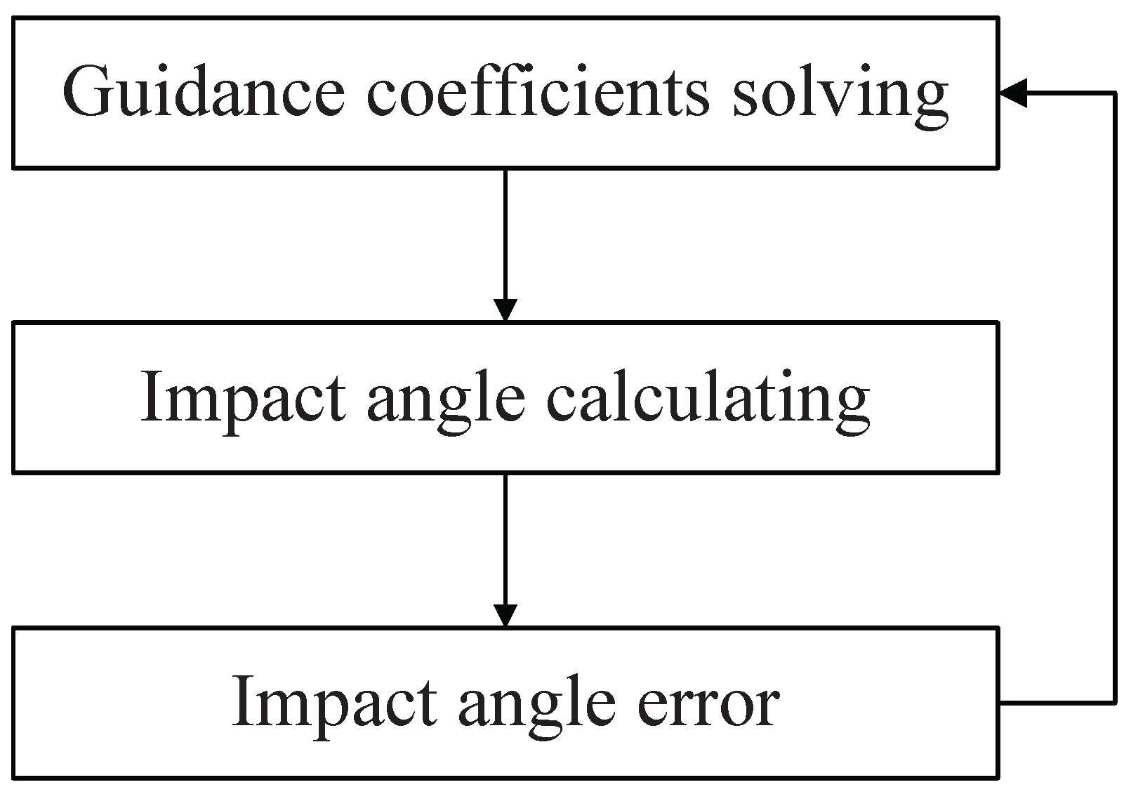
Online updating of polynomial coefficients is a commonly used solution for the closed-loop implementation of polynomial guidance law, especially when the expression of the command maintains an analytical form. For the newly designed guidance law, the block diagram based on the online updating is shown in Figure 3.
Yet, there are two main drawbacks that undermine the practicality of this method. (1) Some guidance laws based on online solution demand extensive computing resources and long calculation time, posing challenges to practical deployment. (2) The recalculated coefficients cannot ensure consistency with the initially determined trajectory, particularly at close ranges (small R values). This inconsistency poses substantial challenges to the reliability and effectiveness of the guidance. To further investigate the second problem, the following theorem is introduced according to the properties of systems of polynomial equations.
Theorem 1.
Let y ( x ) , x x 0 , x f be a fifth-order polynomial, the solution satisfies a system of six nonlinear boundary conditions defined as EX | x = x 0 , x = x f = B at x = x 0 and x = x f . The solution set of the polynomial coefficients is S 1 ( x ) , S 2 ( x ) where S 1 ( x ) S 2 ( x ) . Define a third point as x = x m satisfying x m x 0 and x m x f , the boundary condition values involving x = x m and x = x f are B m . If a new set of boundary condition values involving x = x m and x = x f are B ^ m , and B ^ m B m . Then the solution set of the polynomial coefficients S 1 m ( x ) , S 2 m ( x ) determined by the newly updated boundary conditions must satisfy S 1 m ( x ) S ( x ) and S 1 m ( x ) S ( x ) .
This can be readily demonstrated via proof by contradiction.
Proof. 
Suppose the polynomial curve Q ( x ) satisfies boundary conditions EX | x = x 0 , x = x f = B and EX | x = x m , x = x f = B m if Q ( x ) = S ( x ) S 1 m ( x ) , S 2 m ( x ) were also able to simultaneously satisfy EX | x = x m , x = x f = B ^ m , this would contradict the given condition B m B ^ m . Consequently, the initial assumption Q ( x ) = S ( x ) fails to hold. □
In the present study, the small-angle approximation is employed in the mathematical formulation, particularly in establishing the boundary condition equations and deriving the expressions for acceleration and flight path angle which are shown in Equations (7)–(9). Therefore, the computed boundary values derived from Equation (14) exhibit inherent deviations from the actual boundary condition values.
To address this issue, a solution switching strategy is introduced. Since the acceleration along the trajectory corresponding to certain polynomial coefficients can be estimated once the value of the coefficients are determined, it is rational to set the estimated acceleration as a standard for the selection between the two solutions of the polynomial coefficients described by Equation (15). The adopted evaluation criterion is defined as: Within the range of x x 0 , x f we assess whether the extremum of acceleration (calculated based on the polynomial coefficients obtained at the current point) remains sufficiently small.
For analytical convenience, we define an equivalent acceleration as
a ^ = d θ d x V 2 = a cos ( θ )
When the flight path angle is small, the acceleration situation of the trajectory can be reflected by the newly defined equivalent acceleration. Substitute Equation (9) into Equation (26), then set the derivative of a ^ with respect to x to zero, and we have
a ^ = V 2 20 λ 5 x 3 + 12 λ 4 x 2 + 6 λ 3 x + 2 λ 2
V 2 ( 60 λ 5 x 2 + 24 λ 4 x + 6 λ 3 ) = 0
Thus, the x-coordinates of the extremum points are obtained as
x e x 1 = 2 λ 4 + 4 λ 4 2 10 λ 5 λ 3 10 λ 5 x e x 2 = 2 λ 4 4 λ 4 2 10 λ 5 λ 3 10 λ 5
Considering Equation (27) and using the x-coordinates of the trajectory’s initial point, terminal point, and two extremum points, the extreme values of the equivalent acceleration are given as
a ^ e x 1 = 20 λ 5 x 0 3 + 12 λ 4 x 0 2 + 6 λ 3 x 0 + 2 λ 2 V 2 a ^ e x 2 = 20 λ 5 x e x 1 3 + 12 λ 4 x e x 1 2 + 6 λ 3 x e x 1 + 2 λ 2 V 2 a ^ e x 3 = 20 λ 5 x e x 2 3 + 12 λ 4 x e x 2 2 + 6 λ 3 x e x 2 + 2 λ 2 V 2 a ^ e x 4 = 20 λ 5 x f 3 + 12 λ 4 x f 2 + 6 λ 3 x f + 2 λ 2 V 2
The extremum point is considered to be valid only if the value of x meet the condition that x e x [ x 0 , x f ] . Based on (30), it is apparent that once the initial conditions and impact constraints are specified, the extreme value of equivalent acceleration can be determined, then the polynomial coefficient solution for practical applications is selectable.
In practical applications, we can simultaneously compute the two sets of polynomial coefficient solutions at the current point and derive their extrema. By comparing the two solutions, we obtain the minimum absolute values of each set. The solution with the smaller minimum absolute value is selected. This criterion, based on evaluating the minimum absolute values, allows for dynamic switching between solutions during closed-loop flight. However, it should be noted that calculating polynomial coefficients at every simulation step would significantly increase the computational burden of full-trajectory calculations and compromise the practicality of the guidance law.
Accordingly, we employ an approach of solving polynomial coefficients at multiple discrete points along the trajectory. This approach maintains the validity of polynomial solutions while substantially reducing computational resource requirements. To validate this method, two scenarios are used for comparison: (1) Baseline case: Trajectory replanning under the small-angle assumption, consistent with the original manuscript, without polynomial coefficient solution transformation; (2) Solution switching: Trajectory replanning with polynomial coefficient solution switching strategy.
As evidenced by the illustrations in Figure 4, the polynomial coefficient switching strategy is more appropriate for practical implementation for eliminating oscillations and acquiring enhanced trajectory smoothness.

4.3. Positional Error Elimination

While polynomial coefficients can be recalculated at multiple discrete points along the trajectory, to ensure computational efficiency, these coefficients remain constant between successive recalculation points. The static coefficients are not capable to account for dynamic variations in the interceptor-target relative relationship, particularly in scenarios involving positional errors or other measurement inaccuracies. Therefore, a supplementary acceleration term is employed to maintain the trajectory and eliminate positional errors.
The guidance law (21) can be modified as
a = N p ( x ) V q ˙ + a c y
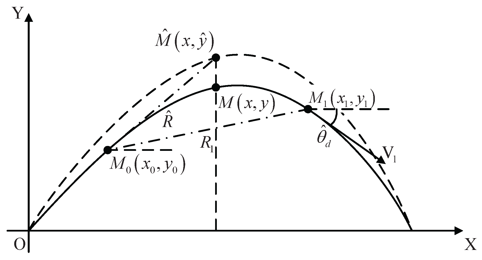
Figure 5 illustrates the geometric relationship of the trajectory with positional error.
The solid line depicts the interceptor’s ideal trajectory, whereas the dotted line illustrates the trajectory with positional error. The ideal position corresponding to the horizontal coordinate x is presented by M ( x , y ) , the actual position including positional error is M ^ ( x , y ^ ) . The positional error is expressed as Δ y = y ^ y . Defining a point M 0 as the beginning point of the eliminating process. Another point M 1 is on the ideal trajectory, the objective of error elimination command is to accomplish error correction prior to reaching M 1 . Let R ^ be the distance between M 0 and M ^ , while R 1 be the distance from M 0 to M 1 , and θ ^ d the designed flight path angle at M 1 .To mitigate this error while maintaining the desired flight path angle, a supplementary command a c y is introduced as
a c y = a y + a θ
where
a y = K Δ y
The positional error is expressed as Δ y = y ^ y . K > 0 is a coefficient of the command term to eliminate positional error. In Equation (33) a θ is the acceleration command enforcing the flight path angle to follow the expected value determined by the polynomial parameters. In order to obtain a θ , it is necessary to derive the variation in flight path angle θ resulting from the implementation of a y . Considering a = V θ ˙ we have
K Δ y = V θ ˙
Let t ^ f denote the flight time required for error correction from M ^ to M 1 in Figure 5 of the manuscript. Integrate (34) with respect to t over the interval [ t ^ 0 , t ^ f ] yields the predicted flight path angle at t ^ f , where t ^ 0 is the start moment of the eliminating process and t ^ 0 = 0 . Let Δ y at the ending point of the eliminating process be 0, θ ^ f be the flight path angle at M 1 . we have
K Δ y 0 t ^ f = 0 t ^ f V θ ˙ d t K V Δ y t = t ^ f Δ y t = 0 = θ ^ f θ K V y 1 y = θ ^ f θ
θ ^ f = θ K V y 1 y
Then the resulting flight path angle error can be written as
ε = θ ^ d + K V ( y 1 y ) θ
Differentiating both sides of Equation (37) with respect to t, and defining the acceleration command used to correct the flight path angle as
a θ = a + K y ˙
where a is the current acceleration, then we have
d ε d R ^ = a θ V 2 cos σ
Based on Equation (39), an equivalent acceleration command is defined as:
a θ = a θ V 2 cos σ
The performance index is subsequently given by Equation (41).
J = 1 2 R 1 0 1 R ^ ζ 1 a θ 2 d R ^ , ζ 1
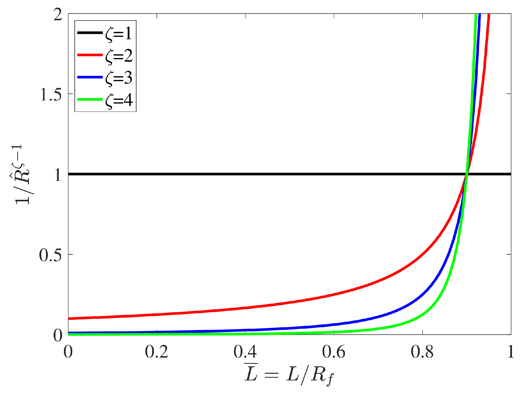
Here we introduced 1 / R ^ ζ 1 and a θ 2 , which reflects the following design principles: (1) Minimizing Energy Consumption: The integral of the square of the acceleration command over the elimination process distance R 1 , 0 is used to characterize energy consumption. By incorporating the penalty function, we aim to minimize energy expenditure during the process. (2) Smooth Transition of Acceleration Command: To ensure a smooth transition of the acceleration command at the end of the eliminating process and reduce abrupt acceleration changes, we designed the penalty function such that the acceleration command is larger in the initial phase and smaller in the end. This effect becomes more pronounced as the parameter ζ increases.
Substituting Equation (40) into Equation (39) and integrating both sides on R ^ [ R 1 , 0 ] yields
ε R 1 0 = R 1 0 a θ d R ^
To adjust both the flight path angle and position values, ε is constrained by the conditions ε R ^ = 0 = 0 and ε R ^ = R 1 = θ ^ d θ ^ f . Thus we have
ε R ^ = R 1 = R 1 0 R ^ ζ 1 2 R ^ 1 ζ 2 a θ d R ^
According to Schwarz inequality, we get
ε R ^ = R 1 2 R 1 0 R ^ ζ 1 R 1 0 R ^ 1 ζ a θ 2 d R ^ J ε R ^ = R 1 2 R 1 0 R ^ ζ 1 d R ^
The equality is valid only when the following condition is satisfied:
R ^ ζ 1 2 = C R ^ 1 ζ 2 a θ
where C is a constant and can be determined by substituting Equations (40) and (42) into Equation (45):
C = R ^ ζ ζ ε R ^ = R 1
Therefore, the term a θ in Equation (32) is obtained as
a θ = ζ R ^ ε R ^ = R 1 V 2 cos σ
Then, substitute Equations (33) and (47) into Equation (32), the optimal guidance term for positional error correction considering angular velocity constraint is given by
a c y = K Δ y + ζ V 2 cos σ R ^ ε
Equation (48) can also be rewritten as
a c y = K Δ y + ζ V cos σ t ^ f ε
Based on the structural composition of the above equation, the operational method of the positional error elimination term is illustrated as Figure 6.
To systematically investigate the parametric selection of K and ζ , we substitute Equation (38) into Equation (47), there is
a + K y ˙ = ζ V 2 cos σ R ^ ε
Then ζ can be expressed as a function of K
ζ = R ^ a + K y ˙ ε V 2 cos σ
Thus, we have established an analytical relationship between K and ζ , which indicates that as K increases, ζ should also be augmented. Let L denote the flown distance and we have R ^ = R 1 L . Normalizing L ¯ as dimensionless flown distance, and L ¯ = L / R 1 . Here, we select R 1 = 20 , the weighting function 1 / R ^ ζ 1 varies with ζ as follows:
Figure 7 clearly illustrates the role of ζ and the designing principle mentioned. From this, we derive the following pattern: as K increases, the acceleration command required to eliminate position errors grows, which amplifies potential greater deviations in the flight path angle. Consequently, a larger ζ becomes necessary to ensure rapid convergence of these amplified deviations. However, it is important to note that the analytical relationship between K and ζ , while guiding their proportional adjustment, is not strictly rigid in practical applications. Nonetheless, the general rule that K and ζ should increase or decrease simultaneously must be adhered to for stable and effective performance.

5. Numerical Simulation

In this section, numerical simulations with various conditions will be conducted to investigate the performance of the new PGIA guidance. Comparative simulations are carried out involving a fourth-order polynomial guidance and an n-order method. The parameters in Table 1 are set as default value in our simulations, and the stopping condition is that the interceptor-target relative range is less than 0.2 m.

5.1. Guidance Law Performance

Four scenarios with different terminal constraints are given in Table 2, where the acceleration ranges are obtained by Equation (30). The initial conditions are set as a 0 = 10 m / s 2 and θ 0 = 10 ° .
The simulation results with various terminal constraints are shown in Figure 8.
From Figure 8, it can be observed that the constraints of the flight time and the flight path angle are achieved at the terminal point under PGIA, and longer expected flight time leads to greater demands for acceleration. In Figure 8e, the value of guidance coefficient N p becomes singular when q is equal to θ . Nevertheless, these singularities do not significantly influence the calculation of the acceleration command as outlined in the preceding discussion. It can also be noted that the proposed guidance law exhibits a smooth transition process for both the flight path angle and acceleration at the starting point. This helps to prevent abrupt alterations in guidance commands in the event of a handover from the midcourse guidance phase to the final phase.

5.2. Performance with Positional Error

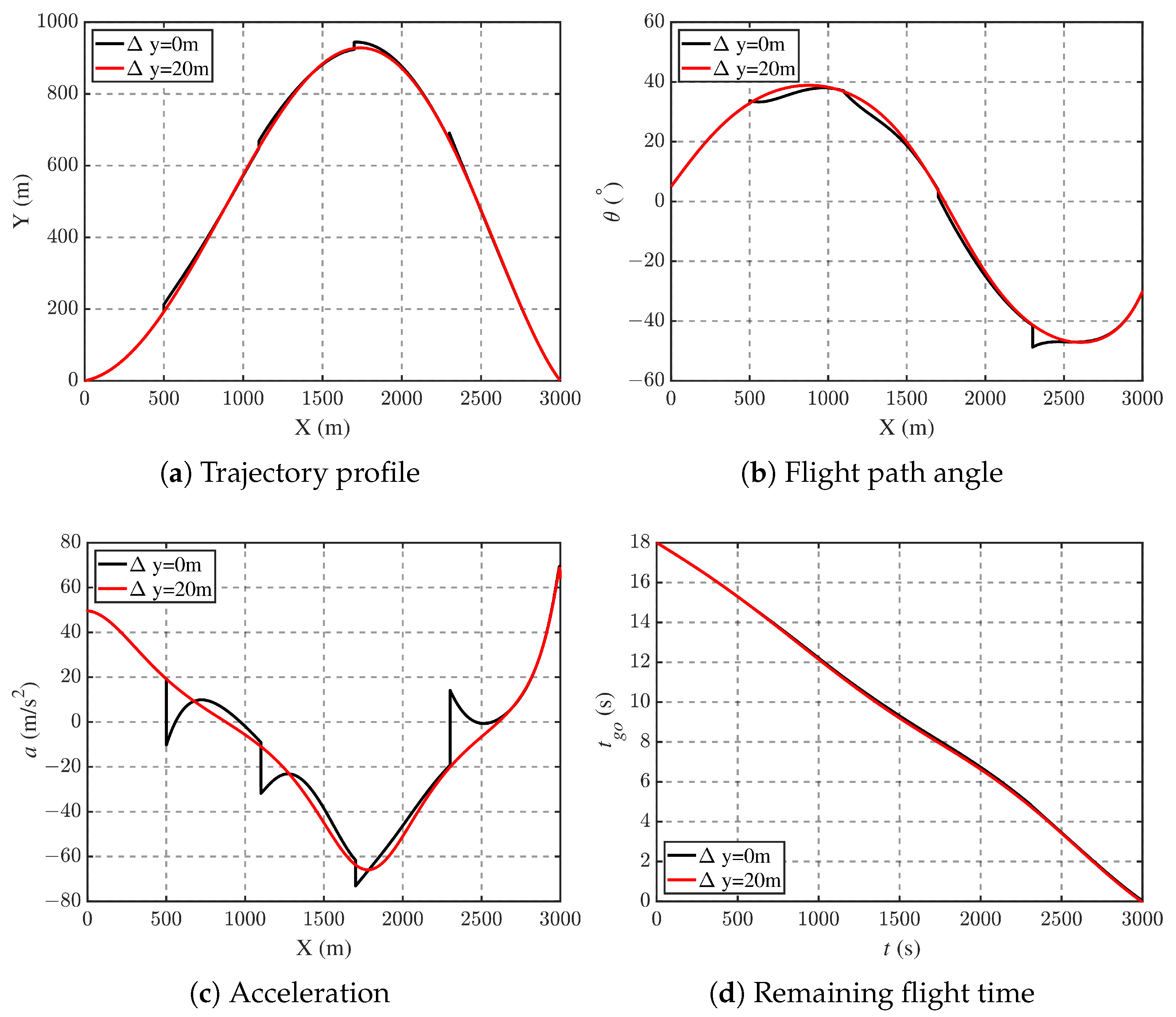
The effectiveness of the positional error eliminating strategy is verified by introducing error along y direction at x = 600 m , x = 1200 m , x = 1800 m and x = 2400 m . The value of Δ y is set as 20 m. The simulation parameters are set as a 0 = 50 m / s 2 , θ 0 = 5 ° , θ f = 30 ° and t f = 17 s . The relative distance between the current interceptor’s position and the correction completion point is assumed to be R ^ = 100 m . The simulation results with K = 1.2 , ε = 1 are presented in Figure 9.
From Figure 9, one can observe that the positional error exerts a notable impact on both the trajectory profile and the flight path angle. A peak in the acceleration command, resulting from the error elimination strategy, emerges when a positional error occurs. Subsequently, the interceptor’s position and flight path angle rapidly stabilize to their ideal values, resulting in the absolute value of the acceleration to diminish. Ultimately, the inclusion of the positional error compensation term ensures high precision in target engagement, as well as precise control over time and angle constraints.

5.3. Comparison Study

In this chapter, to show the advantages of the new designed guidance strategy, comparison studies are conducted. One of the guidance laws employed for comparative simulation is the impact time and angle guidance with sliding mode control (IAGSC) proposed in [21]. This method requires the polynomial coefficients of the LOS profile to be computed at each time step. A critical parameter which ensures the interceptor achieves the desired impact time, is determined offline. Additionally, two coefficients for the sliding mode control must be predefined before the simulation. Another guidance law used for comparison is the augmented polynomial guidance with impact time and angle constraints (APGL) developed in [26], which also necessitates online computation of polynomial parameters.
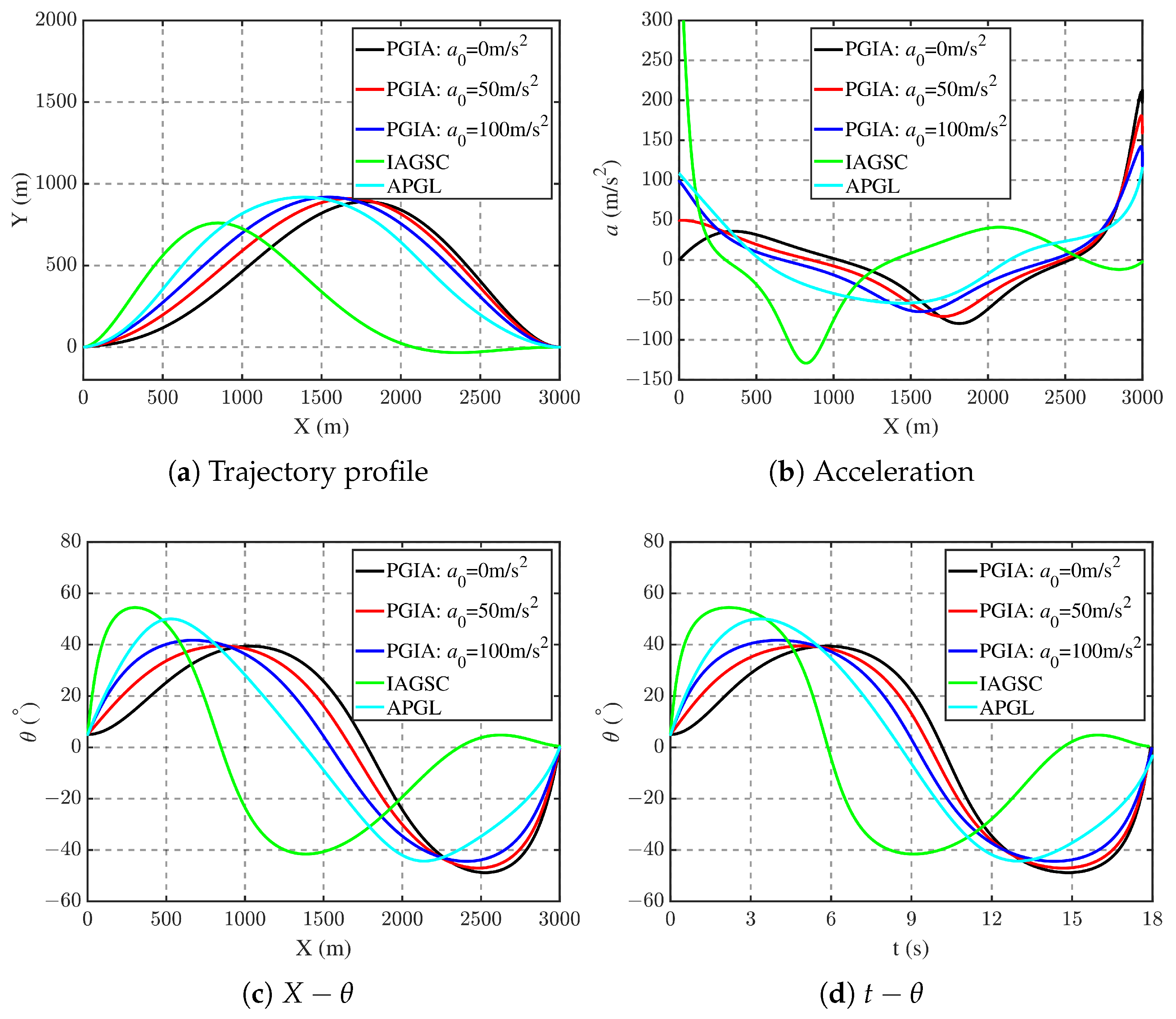
In the first simulation, we primarily demonstrate the new guidance law’s capability in adapting initial conditions. The starting flight path angle is 5°, the impact angle is set as 0° while the desired flight time is 18 s. For the APGL, the value of the initial distance-to-go error ε is designed as 300 m. For the newly proposed PGIA, three initial acceleration values are considered, which are a 0 = 0 m/s2, a 0 = 50 m/s2 and a 0 = 100 m/s2, the coefficient of the positional error elimination term is chosen as K = 1.2 . Figure 10 shows the comparison results of the three guidance laws.
As can be observed, compared with the other two guidance laws, the newly designed guidance law can adapt to the initial acceleration conditions and effectively accomplish the flight. It is also evident that the simulation curves of PGIA and APGL exhibited similarities in terms of acceleration performance and angular change trends. However, it should be clarified that the initial command of APGL is significantly affected by the value of the initial distance-to-go error ε , and IAGSC generates a much larger initial acceleration compared to the other two polynomial guidance laws, which can be noticed from Figure 10b. Moreover, the process of solving the quadratic equation root online in the APGL simulation inevitably causes an increase in the simulating time. In this scenario, APGL requires 57 s for the whole trajectory simulation, while PGIA and IAGSC take only 0.11 s and 0.03 s, respectively.
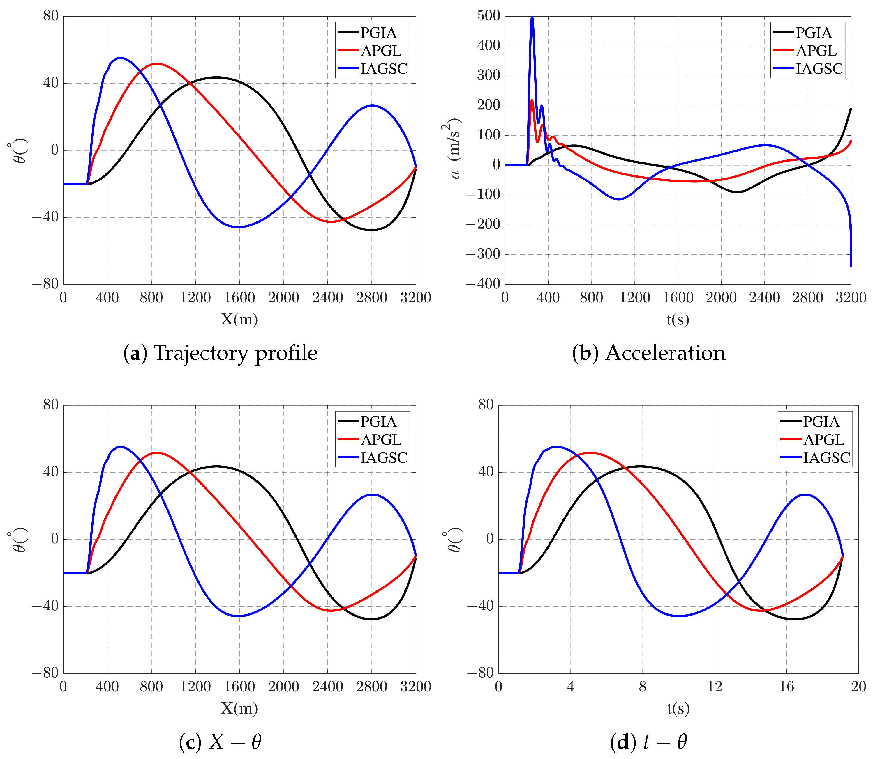
To further highlight the advantages of the newly proposed guidance law during the transition from mid-course to terminal guidance phase, a second-order element was incorporated in the simulation to model the transfer function of a typical interceptor. The second-order element was configured with a natural frequency of 2 Hz and a damping ratio of 0.2, with initial conditions θ 0 = 20 ° , a 0 = 0 m/s2 and terminal constraints θ f = 10 ° . The simulation initiates the terminal guidance phase when the interceptor crosses the position of x = 200 m and the desired flight time of the phase is set as 18 s. Additionally, in order to simultaneously observe the jitter caused by abrupt acceleration changes and further compare the energy consumption characteristics of the three guidance laws, a performance index function is established as
E = t 0 t f a 2 d t
where a is the acceleration command, and t 0 is the starting moment of the terminal phase which is set as 0 s. The simulation results are presented below:
Figure 11a,c,d clearly demonstrate that, after incorporating the transition process, the three guidance laws can still ensure precise target interception while satisfying both flight time and impact angle constraints. However, as evident from Figure 11b,c,d, the smoothness the mid-course to terminal guidance transitions of APGL and IAGSC are significantly impacted by the sudden transients in acceleration commands. The curves exhibits severe oscillations at the transition points, which would inevitably adversely affect the interceptor’s stability during actual flights. Furthermore, the computed performance indexes for the three guidance laws are E P G I A = 4.31 × 10 4 , E A P G L = 4.19 × 10 4 and E I A G S C = 1.24 × 10 5 . Therefore, the novel guidance law exhibits lower energy consumption after incorporating the transient phase, which more distinctly highlights the advantages of the new approach.
The simulation results above demonstrate that the newly proposed guidance strategy delivers high control accuracy and generates smooth acceleration commands throughout the entire trajectory. Unlike the other two guidance laws, PGIA does not require predefined control parameters, which enhances its adaptability to various engagement scenarios. Most importantly, the initial acceleration command can be designed to obtain a seamless transition from the middle-guidance course to the terminal phase of the guidance process.

6. Conclusions

In this study, we begin by reviewing existing research on guidance laws with flight time and impact angle constraints. It is found that the initial states of the interceptor, particularly the initial acceleration and flight path angle are not paid enough attention to. This issue becomes critical during midcourse-terminal guidance handover scenarios, where discontinuities between midcourse-phase acceleration commands and ITAC-generated terminal guidance commands result in abrupt transitions that compromise flight stability.
Leveraging the unique capability of position polynomials to simultaneously model spatial, temporal, velocity-directional, and acceleration parameters, we designed the proposed guidance law in this work. The newly designed approach achieves precise terminal time and angle control while rigorously incorporating initial acceleration and flight path angle constraints, thereby enabling smooth transitions during midcourse-terminal guidance handover scenarios.
First, a fifth-degree polynomial function was formulated, and boundary condition equations were established, including the time-to-go expressed in terms of remaining flight distance. Then the proposed law is represented in a near-PNG form, and two sets of polynomial coefficient solutions are given. The proposed method also enables the estimation of the required acceleration range. Based on this, a solution selection methodology has been developed. In order to ensure the effectiveness of the guidance command determined by polynomial coefficients, the positional error elimination term is incorporated using an optimization-based approach. Comparison simulations are carried out to demonstrate the performance of the proposed guidance law. This strategy provides a new insight to reduce the real-time calculation burden of the polynomial guidance law.

Author Contributions

Conceptualization, X.D.; methodology, X.D.; software, X.D.; validation, S.F.; formal analysis, X.D.; investigation, Y.W.; resources, J.W.; data curation, X.D.; writing—original draft preparation, X.D.; writing—review and editing, X.D.; visualization, X.D.; supervision, J.W.; project administration, J.W.; funding acquisition, S.F. All authors have read and agreed to the published version of the manuscript.

Funding

This research was funded by National Natural Science Foundation of China grant number 52472374.

Data Availability Statement

All data in this paper can be calculated using the provided guidance law and simulation conditions, with no dependency on external databases.

Conflicts of Interest

The authors declare no conflicts of interest. The funders had no role in the design of the study; in the collection, analyses, or interpretation of data; in the writing of the manuscript; or in the decision to publish the results.

References

  1. Jeon, I.S.; Lee, J.I.; Tahk, M.J. Impact-time-control guidance law for anti-ship missiles. IEEE Trans. Control Syst. Technol. 2006, 14, 260–266. [Google Scholar] [CrossRef]
  2. Cho, N.; Kim, Y. Modified pure proportional navigation guidance law for impact time control. J. Guid. Control Dyn. 2016, 39, 852–872. [Google Scholar] [CrossRef]
  3. Chen, Y.; Wang, J.; Shan, J.; Xin, M. Cooperative guidance for multiple powered missiles with constrained impact and bounded speed. J. Guid. Control Dyn. 2021, 44, 825–841. [Google Scholar] [CrossRef]
  4. Zhang, Y.; Wang, X.; Wu, H. Impact time control guidance law with field of view constraint. Aerosp. Sci. Technol. 2014, 39, 361–369. [Google Scholar] [CrossRef]
  5. Dong, W.; Wang, C.; Wang, J.; Xin, M. Varying-gain proportional navigation guidance for precise impact time control. J. Guid. Control Dyn. 2023, 46, 535–552. [Google Scholar] [CrossRef]
  6. Merkulov, G.; Weiss, M.; Shima, T.Y. Minimum-Effort Guidance with Impact Time and Angle Constraints Using Quadratic Kinematics Approximation. In Proceedings of the AIAA SCITECH 2022 Forum, San Diego, CA, USA, 3–7 January 2022; p. 2040. [Google Scholar]
  7. Kim, H.G.; Cho, D.; Kim, H.J. Sliding mode guidance law for impact time control without explicit time-to-go estimation. IEEE Trans. Aerosp. Electron. Syst. 2018, 55, 236–250. [Google Scholar] [CrossRef]
  8. Sinha, A.; Nanavati, R.V.; Ranjan Kumar, S. Three-Dimensional nonlinear impact time guidance using predicted interception point. J. Guid. Control Dyn. 2023, 46, 608–617. [Google Scholar] [CrossRef]
  9. Lee, J.I.; Jeon, I.S.; Tahk, M.J. Guidance law to control impact time and angle. IEEE Trans. Aerosp. Electron. Syst. 2007, 43, 301–310. [Google Scholar]
  10. Zhang, Y.; Ma, G.; Liu, A. Guidance law with impact time and impact angle constraints. Chin. J. Aeronaut. 2013, 26, 960–966. [Google Scholar] [CrossRef]
  11. Lee, J.Y.; Kim, H. Impact time and angle control guidance with rendezvous concept. In Proceedings of the 2018 AIAA Guidance, Navigation, and Control Conference, Kissimmee, FL, USA, 8–12 January 2018; p. 1322. [Google Scholar]
  12. He, S.; Lee, C.H. Optimality of error dynamics in missile guidance problems. J. Guid. Control Dyn. 2018, 41, 1624–1633. [Google Scholar] [CrossRef]
  13. Li, B.; Lin, D.; Wang, J.; Tian, S. Guidance law to control impact angle and time based on optimality of error dynamics. Proc. Inst. Mech. Eng. Part G J. Aerosp. Eng. 2019, 233, 3577–3588. [Google Scholar] [CrossRef]
  14. Yang, X.; Zhang, Y.; Song, S. Two-stage cooperative guidance strategy with impact-angle and field-of-view constraints. J. Guid. Control Dyn. 2023, 46, 590–599. [Google Scholar] [CrossRef]
  15. Zhou, J.; Lv, Y.; Wen, G.; Wu, X.; Cai, M. Three-dimensional cooperative guidance law design for simultaneous attack with multiple missiles against a maneuvering target. In Proceedings of the 2018 IEEE CSAA Guidance, Navigation and Control Conference (CGNCC), Xiamen, China, 10–12 August 2018; pp. 1–6. [Google Scholar]
  16. Lyu, T.; Guo, Y.; Li, C.; Ma, G.; Zhang, H. Multiple missiles cooperative guidance with simultaneous attack requirement under directed topologies. Aerosp. Sci. Technol. 2019, 89, 100–110. [Google Scholar] [CrossRef]
  17. Li, H.; He, S.; Wang, J.; Shin, H.S.; Tsourdos, A. Near-optimal midcourse guidance for velocity maximization with constrained arrival angle. J. Guid. Control Dyn. 2021, 44, 172–180. [Google Scholar] [CrossRef]
  18. Yamasaki, T.; Kikukawa, Y.; Takano, H.; Yamaguchi, I. Terminal Impact Angle Control Guidance Taking Account of Field-of-View Constraint Using a Time-Shifting Sliding Surface. In Proceedings of the AIAA SCITECH 2024 Forum, Orlando, FL, USA, 8–12 January 2024; p. 2207. [Google Scholar]
  19. Kumar, S.R.; Ghose, D. Impact time and angle control guidance. In Proceedings of the AIAA Guidance, Navigation, and Control Conference, Kissimmee, FL, USA, 5–9 January 2015; p. 0616. [Google Scholar]
  20. Tekin, R.; Erer, K.S.; Holzapfel, F. Polynomial shaping of the look angle for impact-time control. J. Guid. Control Dyn. 2017, 40, 2668–2673. [Google Scholar] [CrossRef]
  21. Harl, N.; Balakrishnan, S.N. Impact time and angle guidance with sliding mode control. IEEE Trans. Control Syst. Technol. 2011, 20, 1436–1449. [Google Scholar] [CrossRef]
  22. Tekin, R.; Erer, K.S.; Holzapfel, F. Quartic range shaping for impact time control. In Proceedings of the 2017 25th Mediterranean Conference on Control and Automation (MED), Valletta, Malta, 3–6 July 2017; pp. 1213–1218. [Google Scholar]
  23. Tekin, R.; Erer, K.S. Impact time and angle control against moving targets with look angle shaping. J. Guid. Control Dyn. 2020, 43, 1020–1025. [Google Scholar] [CrossRef]
  24. Tekin, R.; Erer, K.S.; Holzapfel, F. Impact time control with generalized-polynomial range formulation. J. Guid. Control Dyn. 2018, 41, 1190–1195. [Google Scholar] [CrossRef]
  25. Li, H.; Liu, Y.; Li, K.; Liang, Y. Polynomial Guidance for Impact-Time Control Against Maneuvering Targets. J. Guid. Control Dyn. 2023, 46, 2388–2398. [Google Scholar] [CrossRef]
  26. Kim, T.H.; Lee, C.H.; Jeon, I.S.; Tahk, M.J. Augmented polynomial guidance with impact time and angle constraints. IEEE Trans. Aerosp. Electron. Syst. 2013, 49, 2806–2817. [Google Scholar] [CrossRef]
  27. Lee, C.H.; Kim, T.H.; Tahk, M.J.; Whang, I.H. Polynomial guidance laws considering terminal impact angle and acceleration constraints. IEEE Trans. Aerosp. Electron. Syst. 2013, 49, 74–92. [Google Scholar] [CrossRef]
  28. Zarchan, P. Tactical and Strategic Missile Guidance; American Institute of Aeronautics and Astronautics, Inc.: Reston, VA, USA, 2012. [Google Scholar]
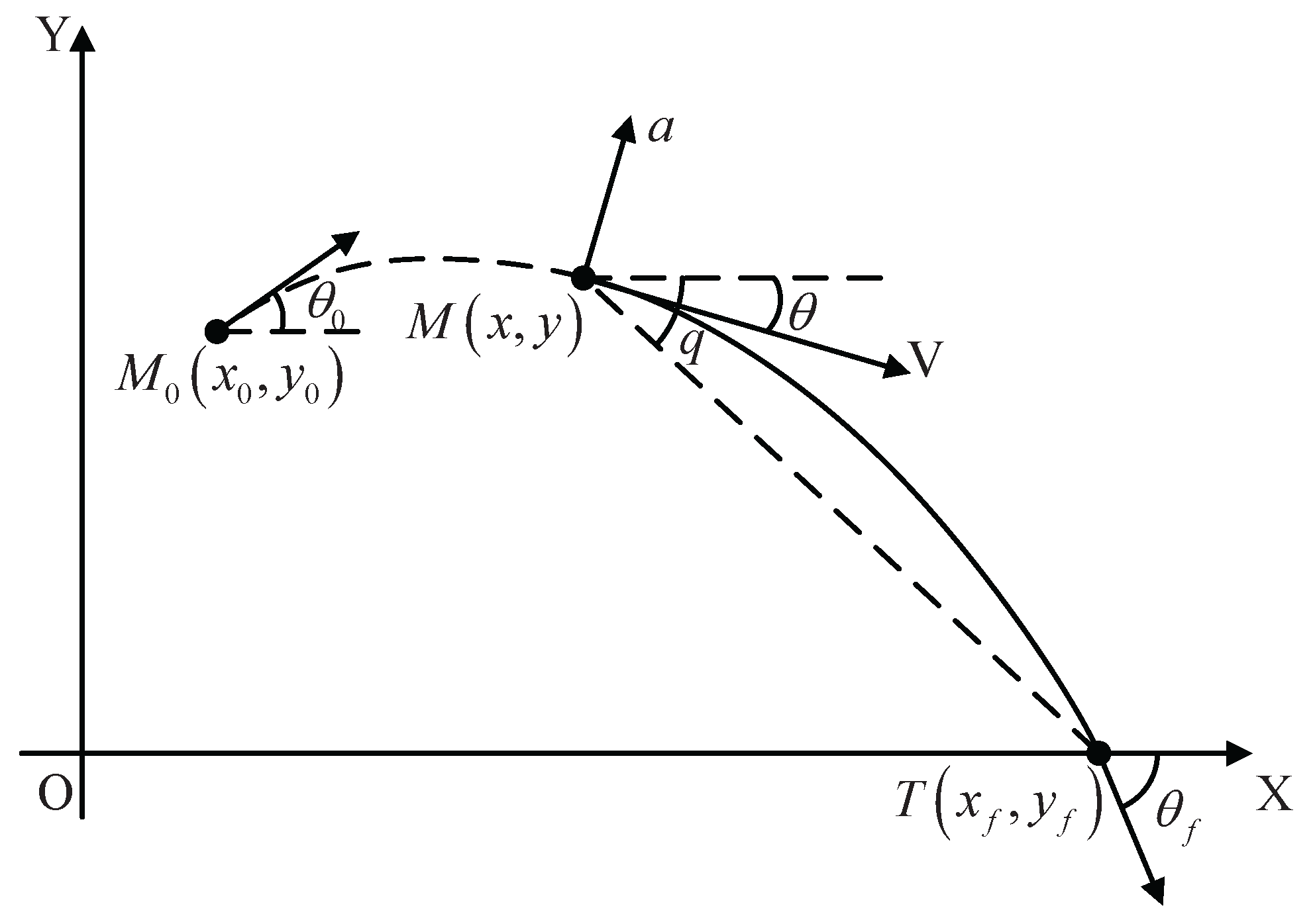
Figure 1. Engagement geometry.
Aerospace 12 00484 g001
Figure 2. Impact angle compensation method.
Aerospace 12 00484 g002
Figure 3. Homing loop of online updating.
Aerospace 12 00484 g003
Figure 4. Beneficial effect of solution switching strategy.
Aerospace 12 00484 g004
Figure 5. Trajectory with positional error.
Aerospace 12 00484 g005
Figure 6. Implementation with positional error elimination term.
Aerospace 12 00484 g006
Figure 7. The weighting function varying with ζ .
Aerospace 12 00484 g007
Figure 8. Performance with different terminal constraints.
Aerospace 12 00484 g008
Figure 9. Trajectory performances for different initial conditions.
Aerospace 12 00484 g009
Figure 10. Comparisons among three guidance laws.
Aerospace 12 00484 g010
Figure 11. Comparisons with second-order element.
Aerospace 12 00484 g011
Table 1. Basic simulation condition.
ParametersValues
Initial interceptor-target distance R3000 m
Missile Velocity V200 m/s
Initial position ( x 0 , y 0 )(0, 0)
Target position ( x f , y f )(3000, 0)
Table 2. Terminal constraints.
CasesImpact Angle (°)Impact Time (s)
1−2016
2−2017
3−2018
4−4016
5−4017
6−4018
Disclaimer/Publisher’s Note: The statements, opinions and data contained in all publications are solely those of the individual author(s) and contributor(s) and not of MDPI and/or the editor(s). MDPI and/or the editor(s) disclaim responsibility for any injury to people or property resulting from any ideas, methods, instructions or products referred to in the content.