1. Introduction
As the core component of an aircraft, the aeroengine is a thermal machine that works in a harsh environment of high temperature, high pressure, and high speed. It is not only the power source of an aircraft but also an important driving force for the advancement of the aviation industry. The transformation of aeroengine technology has promoted many innovations in the history of human aviation development [
1]. After hundreds of years of technological iteration and development, aircraft engines have continued to develop towards a high thrust-to-weight ratio and high performance, from piston to jet to turbofan. With its strong power, low fuel consumption, and low noise, the turbofan engine has become the commercial aircraft engine with the widest range of use, the largest installed capacity, and the greatest development prospects, and has become the focus of research [
2].
As an important component of the turbofan engine, fan blades are subject to high centrifugal loads, aerodynamic loads, and foreign object impact damage, which have a significant impact on the performance of the turbofan engine. Fan blades have a long blade length, a wide blade chord, a large twist angle, and a complex shape. Thinning blades is conducive to meeting high efficiency/low weight requirements, while thickening blades is conducive to meeting high strength/high stability requirements. This contradictory condition often leads to the blade shape being designed as a complex swept structure, putting higher requirements on the structural design and optimization technology of fan blades [
3]. In the field of modern aviation, the flight environment is becoming increasingly complex. As well as achieving light weight and manufacturability of fan blades, it is also necessary to achieve higher strength and longer fatigue life. Therefore, exploring advanced fan blade intelligent design technology is an important way to improve blade quality and design efficiency [
4].
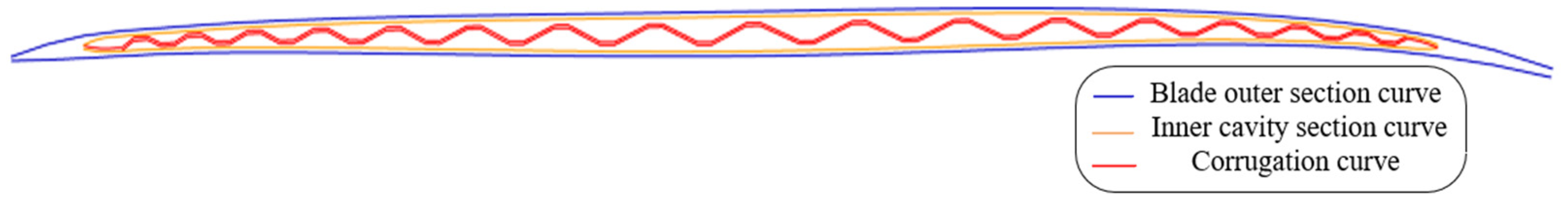
Traditional fan blades are usually manufactured through envelope forging and machining to obtain the final shape. The heavy weight of solid forgings severely limits the improvement of the thrust-to-weight ratio. If the desired blade external shape can be achieved with a lighter weight, the engine’s operating efficiency will be greatly improved, and the application of an internal hollow structure is a very effective method of doing this [
5]. After years of development and verification, Rolls-Royce successfully developed the second-generation wide-chord hollow fan blade with a titanium-alloy three-layer structure using the superplastic forming/diffusion bonding (SPF/DB) combined process technology in 1992. According to existing industry standards, the established process includes diffusion bonding between the two wall plates and a middle core plate, succeeded by superplastic forming to generate internal corrugated reinforcement ribs [
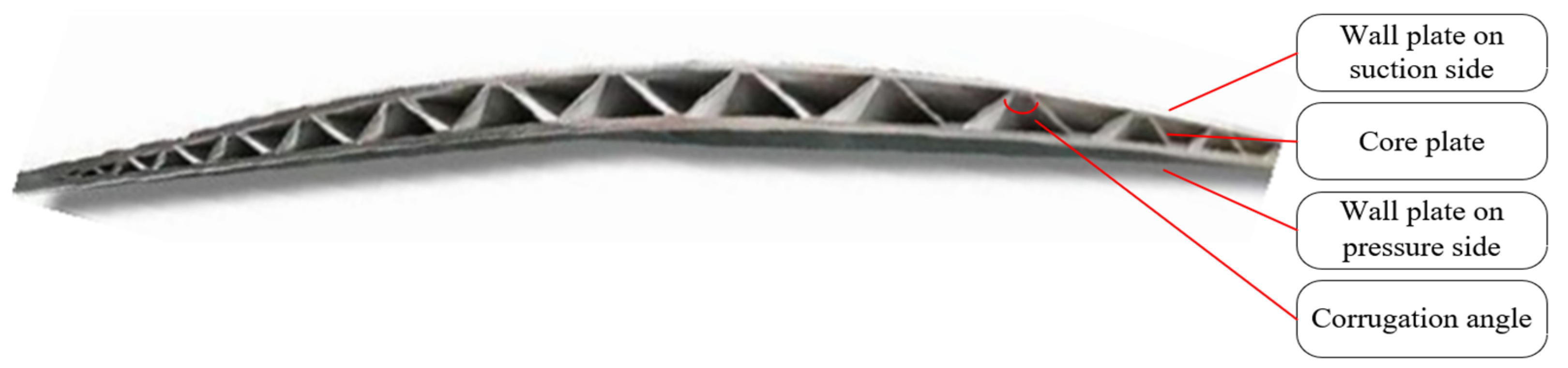
6]. As shown in
Figure 1, the interlayer in the middle of the titanium-alloy wall plates adopts a triangular corrugated structure [
7]. The corrugations are formed in the chord direction, and several weight-reducing cavity channels and ribs are formed in the span direction. Blades with this structure are not only light in weight but also have strong load-bearing capacity and longer service life, so they are widely used in various types of aircraft [
8].
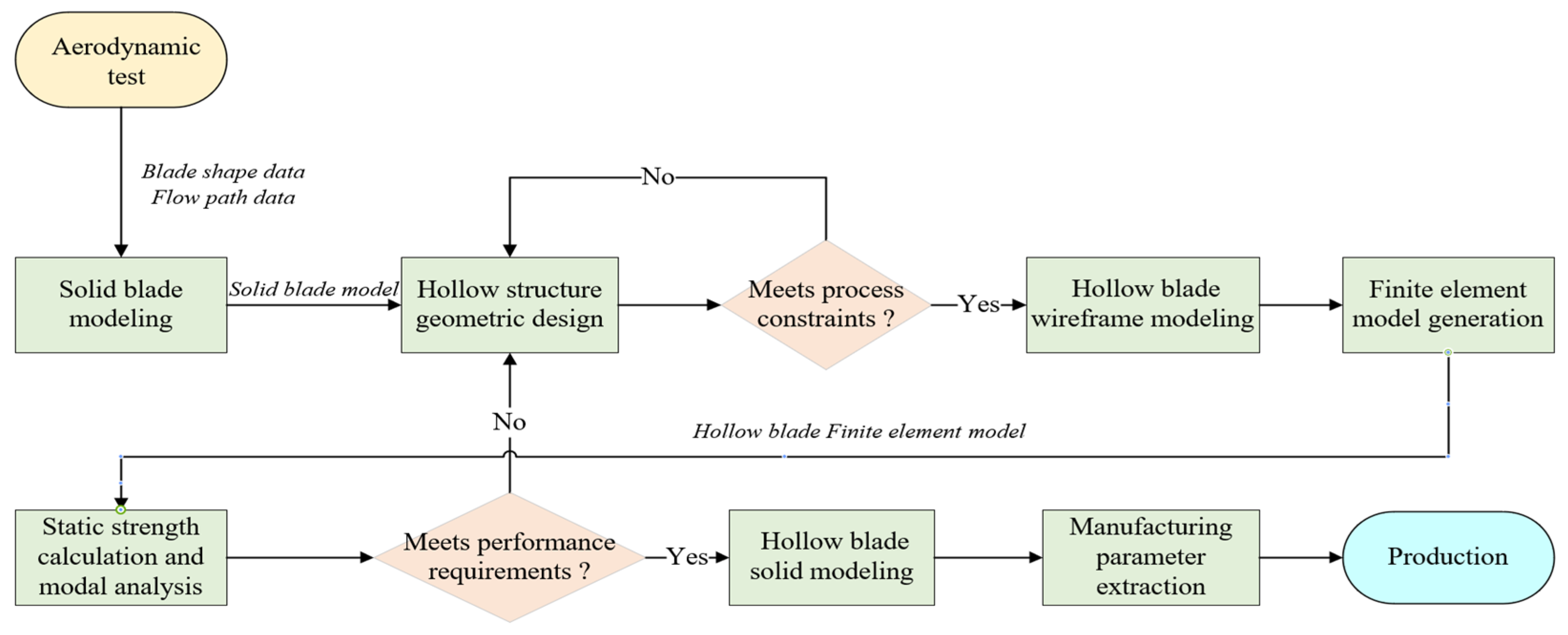
The performance of an engine fan depends on the blade structure, so it is necessary to continuously optimize the geometric structure of blades. At present, the design process of iterative trial and error is mainly adopted. As shown in
Figure 2, for a specific type of hollow blade, the steps of geometric structure design, CAE finite element model generation, static strength calculation, and modal analysis in the process usually require several iterations. Among them, the geometric structure design of the hollow blade is the foundation for structural optimization. Only by building a hollow blade model based on the design parameters can its structure be optimized and iteratively calculated, and finally the design result that meets the performance requirements can be obtained. In addition, the geometric structure design result not only needs to meet the performance requirements of subsequent CAE analysis but also needs to meet the constraints of the manufacturing process. For example, its diffusion bonding strength is directly related to the wall plate thickness, core plate thickness, and its connection angle (corrugation angle) [
6].
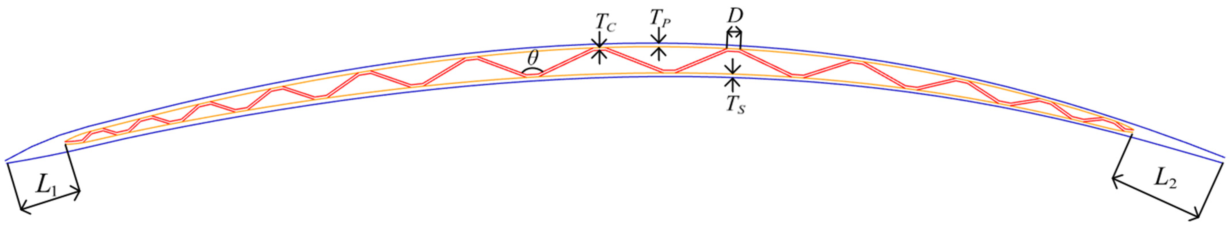
Due to the progress of hollow blade manufacturing technology in recent years, design parameters such as solid part length and wall and core plate thickness are allowed to take variable values at different positions of the blade, which greatly increases the number of design parameters. At the same time, in order to improve the performance of hollow blades, the setting of design parameters is more complicated. At present, the main design parameters of a hollow blade cross-section are shown in
Table 1 and
Figure 3. Among them,
and
change along the chord direction, and the angle
of each corrugation is also different. When the hollow blade model is determined by several design cross-sections, there are often hundreds of parameters that need to be set in actual design.
The traditional design method that relies on the engineer’s own experience for trial and error adjustment has seriously reduced the design efficiency and quality of hollow blades and can no longer meet manufacturing requirements. Therefore, it is urgent to study the intelligent design method and develop an intelligent design system for the geometric structure of the aeroengine three-layer hollow fan blade to meet the automatic parametric design requirements of the hollow fan blade geometric structure under complex aerodynamic shape and a large number of design constraints. This will support the automation of the multi-disciplinary optimization design process, improve the quality and efficiency of hollow blade structural design, and achieve efficient design and performance optimization of the three-layer hollow fan blade.
2. Related Work
In the research related to the design of aeroengine blades, there is a lot of experience in the study of aerodynamic shape design, including parametric design methods for fan blades [
9,
10,
11] and optimizing the shape of blades based on aerodynamic performance using different optimization methods [
12,
13,
14], while there are few public studies on the internal geometric structure design methods of hollow fan blades. However, due to the lightweight requirements of aeroengine blades, the study of hollow blade design is becoming a new research trend. And since the blade outer surfaces are almost all free-form surfaces, it is very difficult to directly design the inner cavity. Therefore, the current mainstream hollow blade geometric structure design method is the cross-sectional design method. Salnikov [
15] created a parametric 3D model of a hollow fan blade in the ANSYS APDL environment, dividing the design cross-section into constant cross-sections, variable cross-sections, and interpolated cross-sections, which greatly reduced the design parameters and improved the efficiency of subsequent parameter optimization. However, this paper did not discuss how the geometric structure of the hollow blade was designed, and because APDL modeling cannot handle more complex geometric design requirements, for example, the smoothness of the surfaces and ribs was ignored, which reduced the structural performance of the blade. Zhang and Chen [
16] proposed a parametric modeling method for the H-shaped hollow fan blade, which selected five cross-sections for design and spline interpolation modeling, with the rib positions and the wall plate thickness on a cross-section symmetrically distributed. The modeling efficiency of this method is high, but since the number and position of the design cross-sections are fixed and the design in a cross-section is limited to symmetrical distribution, the degree of freedom in the design is greatly reduced and cannot meet the design requirements of different types of hollow blades.
Most of the existing hollow fan blade geometric design methods restrict the blade geometric structure, such as reducing the number of design cross-sections, keeping the wall thickness constant and distributing the ribs evenly to reduce design parameters, simplify the design process and reduce the difficulty of modeling. But the reduction in design parameters and the simplification of the structure undoubtedly also limit the performance of the hollow blade and cannot meet the design requirements of different types of blades, as shown in
Table 2. The lack of automation in the hollow blade structure design method also limits the efficiency of performance optimization. The orthogonal experimental design (OED) method used in existing research [
17,
18] not only has a very high computational cost but also cannot obtain the optimal solution for parameter design. At the same time, the constraints of process and practice are not considered in the existing design process, which makes it difficult to apply the design results to actual production.
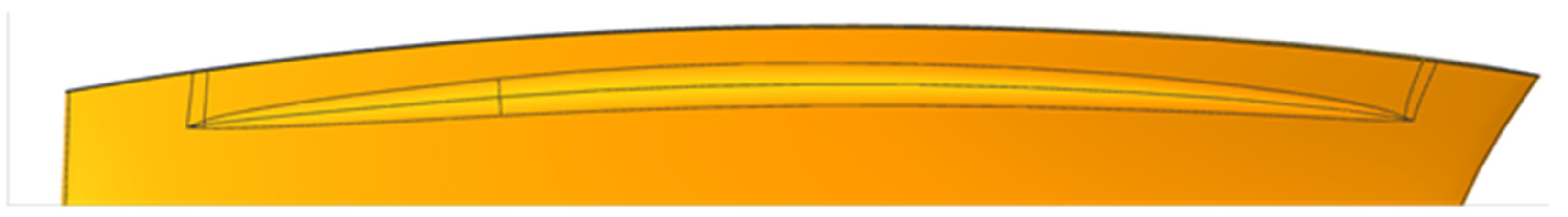
In the cross-section design method of wide-chord hollow fan blades, the inner cavity curve is generally obtained by offsetting the blade outer curve toward the inner cavity in a design cross-section according to the wall plate thickness parameter. The blade’s outer shape, created based on aerodynamic experiment data, is mostly splicing surfaces, and there are a large number of broken surfaces caused by the thinning feature at the blade tip, as shown in
Figure 4. This makes the blade cross-section curves complex, resulting in difficulties in offsetting, and the inner cavity curves are also subject to multiple constraints to meet the blade performance and manufacturing process requirements, including distance and smoothness, etc. Therefore, it is necessary to study the complex curve offset method to see if it is suitable for hollow blade geometric design.
The current research on curve offset can be mainly divided into equidistant offset algorithms based on control points and approximate offset algorithms based on sampling fitting. Kim [
19] proposed an equidistant approximate offset algorithm for Bezier curves, which obtained an approximate polynomial curve by offsetting control points and then calculating their Gaussian graph approximation. This method can not only obtain irrational polynomial curves but also maintain the end point tangent characteristics of multi-part curves after offsetting. However, in some cases the Gaussian approximation method will cause cusps in the offset curve, and its applicability is not wide. Li [
20] proposed a curve offset algorithm based on progressive iterative approximation: The geometric feature points on the original curve are selected to offset. Then, this paper iterates to perform error analysis and adds the maximum error point to the feature point sequence until the curve meets the accuracy requirements after fitting the offset feature points. This algorithm effectively reduces the number of control points of the offset curve while maintaining the curve features after offsetting, but the progressive iterative process undoubtedly increases the computational cost. Zhao [
21] proposed a circular Bezier curve offset algorithm based on an approximate offset. First, the approximate curve is obtained by sampling, fitting, and offsetting, then the self-intersection problem in the approximate curve is segmented, and finally the control points are solved by the least squares method to obtain the offset curve of the same order as the original curve. However, this method is not effective in offsetting complex curves, and its engineering applicability is not strong.
At the same time, in the structural design of wide-chord hollow fan blades, the process and performance have certain smoothness requirements on its spanwise ribs and inner cavity surfaces, so it is necessary to smoothen the geometric design results of hollow blades. Currently the commonly used curve smoothing algorithms include the smoothing method based on the least squares method, the curve smoothing method based on the minimum energy method, the curve smoothing method based on wavelet analysis, and the point selection modification method, etc. Among them, the curve smoothing method based on the minimum energy realizes the smoothing of the curve under specified constraints by minimizing the curve energy function value. Since its energy function and constraint conditions can be adjusted accordingly, it is widely used in the curve smoothing problem under multiple constraints.
Imre [
22] used the weighted average of the square integral of curve curvature and the deviation of the sampling points as the energy function and used the coordinates of some control points on the curve as variables. In the process of minimizing the energy, other control points were kept unchanged to smooth the curve. This algorithm reduces the computational complexity of the solution, but the selection of variable control points affects the quality of smoothing results. Takezawa and Matsuo [
23] implemented a minimum-energy B-spline curve smoothing method based on the reinforcement learning method. In view of the difficulty in optimizing the curve energy function due to the large number of control points, the efficiency of minimizing the energy function was effectively improved through the reinforcement learning method. This algorithm works well on point cloud fitting curves, but it is not effective for smoothing curves with a small number of control points.
In summary, for the design of aeroengine hollow fan blades where product performance requirements and manufacturing process constraints are becoming increasingly stringent, it is necessary to propose a more sophisticated and intelligent geometric structure design method combined with process constraints and performance requirements. Based on geometric algorithms such as complex curve and surface offset and smoothing, this paper proposes an intelligent design method for the geometric structure of the three-layer hollow fan blade, so as to realize the automatic parametric design and modeling of hollow blade geometry under the complex aerodynamic shape and a large number of process constraints and performance requirements, and to improve the quality and efficiency of hollow blade structure design.
3. Methodology and System Architecture
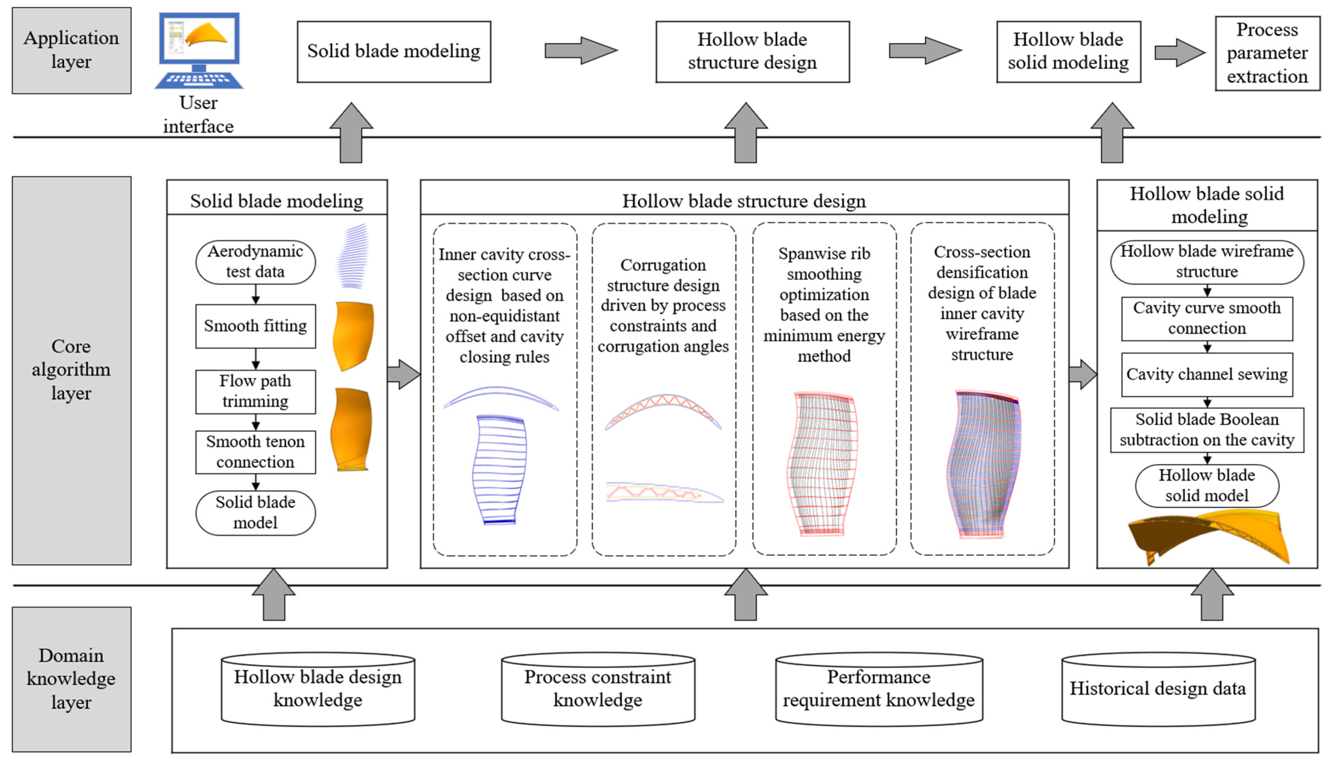
This paper combines hollow fan blade design knowledge, manufacturing process constraints, and geometric algorithms to propose an intelligent parametric design solution and system development method for the geometric structure of the three-layer hollow fan blade. The system solution and architecture are shown in
Figure 5, which consists of the application layer, core algorithm layer, and domain knowledge layer.
The application layer provides users with various design functions, including solid blade modeling based on aerodynamic experiment data, hollow blade wireframe structure design, hollow blade solid modeling, automatic finite element meshing, and manufacturing process parameter extraction. The application layer also provides interactive interfaces for various application operations, including selecting original design data such as blade shape data and flow path line data obtained through aerodynamic experiments, setting various hollow blade geometric structure design parameters, etc., and passing the design parameters set by the user to the core algorithm layer.
The core algorithm layer contains various algorithms for realizing the design of the hollow blade geometric structure. According to the functions and design parameters set by the application layer, it calls the relevant rules, knowledge, and constraints of the knowledge layer to automatically design the complex geometric structure of the hollow blade.
The knowledge layer stores hollow blade design knowledge, manufacturing process constraint knowledge, performance requirement knowledge, and historical design data, etc., to provide basic data and domain knowledge support for the system. The content of the knowledge layer can be continuously updated, accumulated, and expanded, so that the entire system can be continuously updated and iterated to meet the design requirements of hollow blades of different models and processes and maintain the reliability and flexibility of the system.
The main functions of the system are as follows:
First, the blade shape data and flow path data that meet the performance requirements obtained through aerodynamic experiments are selected. The shape data points are fitted into a smooth solid blade model and trimmed based on the flow path data. Then, the trimmed solid blade is smoothly spliced with the standard specification tenon to achieve complete solid blade modeling.
- 2.
Hollow blade structure design:
The structure design is the key and difficulty of hollow blade design, and it is also the problem that this paper focuses on solving.
In order to accurately describe the hollow structure characteristics of the blade chord and span direction and quickly realize the optimization design and automatic finite element meshing, this paper proposes a hollow blade wireframe structure design method based on a complex curve non-equidistant offset and smoothing algorithm, which combines the hollow fan blade design knowledge and manufacturing process constraints.
The basic idea of the algorithm is as follows: First, according to the structural characteristics of the blade, the position and number of design cross-sections are reasonably selected along the blade span direction. Then, the inner cavity curves and the core corrugations are parametrically designed in each cross-section, and the diffusion bonding ribs are smoothed along the span direction. Finally, the cross-section interpolation densification is performed as needed to quickly realize the optimization design of the inner cavity wireframe structure.
The key algorithms are as follows:
This paper proposes an inner cavity cross-section curve design method based on non-equidistant offset and cavity closing rules. In the design cross-section, based on the design parameters such as the wall plate thickness and the solid part length of the blade leading and trailing edges, the blade’s outer cross-section curves on the pressure and suction sides are non-equidistantly offset, and the cavity closing shape is locally adjusted based on the design rules to obtain the inner cavity cross-section curves that meet the design parameters and process constraints.
The core plate corrugation has high design requirements and complex structure, which is the key to the design of the entire hollow blade.
This paper proposes a parametric design method for the corrugation structure in the design cross-section driven by process constraints and corrugation angles. The intersection point of the central ridge curve of the blade inner cavity and the cavity curves of each cross-section is selected as the design starting point, and the undulating corrugation structure is generated along the chord direction to both sides. First, the angle parameter value of the corrugation structure is set according to the strength test data of the diffusion bonding process of the wall plate and the core plate. By rotating the connecting line of the corresponding corrugation angle and intersecting the inner cavity cross-section curve in three dimensions, the corrugation wireframe structure of the specified angle is obtained. The corrugation structure is generated one by one until the cavity closing constraints are met to realize the design of the complete core corrugation structure in the cross-section. At the same time, the corrugation shape of the cavity closing parts and the blade tip transition cross-sections need to be adjusted in combination with process constraints.
The hollow blade wireframe structure directly designed based on the corrugation angle data determined by the diffusion bonding process test may have distortion of the rib structure of the spanwise connected core plate corrugations of each cross-section due to excessive changes in the inner cavity shape, which may affect the diffusion bonding process and cause stress concentration Therefore, this paper proposes a spanwise rib smoothing optimization method based on the minimum energy method, introduces the corrugation angle change term into the energy function of the rib guide curve, and performs smoothing optimization design under the conditions of satisfying the design and process constraints. The main constraints include the angle difference constraint of adjacent corrugations in the chord direction, the angle constraint of the minimum thickness of the core plate after forming, and the corrugation angle range constraint in the cross-section.
When designing the blade inner corrugation structure, if too many design cross-sections are selected, the number of design parameters will be too large and the design efficiency will be reduced, while too few design cross-sections cannot fully express the hollow blade structure. Therefore, this paper proposes a cross-section densification method for the hollow blade wireframe structure. By performing shape design and smoothing optimization of the inner cavity curves and corrugations in a small number of key position cross-sections, the main characteristics of the hollow blade wireframe structure are determined, and then cross-sections are interpolated and densified. The inner cavity cross-section curves are obtained by interpolation calculation of the design parameters, and the corrugation structures are designed through the intersection position of the smoothing spanwise rib guide curves to design a hollow blade wireframe structure with a denser spanwise cross-section, thereby improving the integrity of the design result.
- 3.
Hollow blade solid modeling and integrated application:
The corresponding inner cavity curves of each cross-section are connected smoothly and sewn to obtain the blade cavity channel entities. The solid blade model is used to perform Boolean subtraction on the cavity channel entities to obtain the hollow blade solid model. Finally, the key geometric parameters and process parameters of the hollow blade design are extracted, and the automatic finite meshing, the subsequent multidisciplinary optimization design, and intelligent manufacturing application integration and process automation are supported.
4. Research and Implementation of Key Algorithms
The key and difficulty of hollow blade design lie in the design of hollow inner cavity structure based on the solid blade model obtained from aerodynamic experiment data. The hollow structure must not only meet the manufacturing process constraints but also meet the lightweight requirements while ensuring application performance. This goal undoubtedly exacerbates the difficulty of geometric structure design. Therefore, this paper focuses on the design method of hollow geometric structure, including the inner cavity cross-section curve design method, the core plate corrugation structure parametric design method, the rib spanwise smoothing optimization method, the blade wireframe structure densification method, and the hollow blade solid modeling method.
4.1. Inner Cavity Cross-Section Curve Design Method
Since the pressure side and suction side of the blade outer shape are both composed of free-form surfaces, it is difficult to directly design the accurate hollow structure by design parameters. Therefore, this paper adopts the cross-sectional design method to carry out the hollow structure design based on the blade outer shape cross-section curves. This method can not only avoid the inconvenience caused by complex free-form surfaces but also ensure the design’s accuracy by controlling the number and position of the cross-sections.
If the design is performed using the plane cross-section, the incomplete design cross-section will be generated due to the twisted shape of the blade tip, which will lead to many problems in the structural design process, such as difficulty in determining the solid part length of the leading and trailing edges and the complexity of the tip transition part design. Therefore, this paper adopts the spanwise isoparametric cross-section for the hollow structure design. The cross-section position is the isoparametric curve on the mid-surface of the cavity, which is obtained by fitting the midpoints of the corresponding connecting lines between the pressure and suction outer surfaces.
The blade outer pressure and suction side surfaces are first cut based on the design height of the solid part of the blade tip and root. The corresponding sampling on the cut pressure and suction side surfaces obtains the point series, and the midpoints of the corresponding connection lines are fitted to obtain the mid-surface. The mid-surface UV parameter directions are controlled to be spanwise and chordwise. The isoparametric curves are constructed along the spanwise direction, and their spanwise positions are the design cross-section positions. The isoparametric curves are projected onto the outer surfaces on both sides along the blade thickness direction to obtain the outer cross-section curves, as shown in
Figure 6.
The design parameters of the inner cavity cross-section curves include the length of the solid parts at the leading and trailing edges and the thickness of the pressure and suction wall plates, as well as the cavity closing rule parameters. In order to improve the performance of the hollow fan blade, these design parameters are all variable parameters, among which the length of the solid part of the leading and trailing edges varies along the span direction, and the thickness of the pressure and suction wall plates varies along both the span and the chord direction. For example, the suction wall plate thickness distribution of a certain model of blade is shown in
Figure 7.
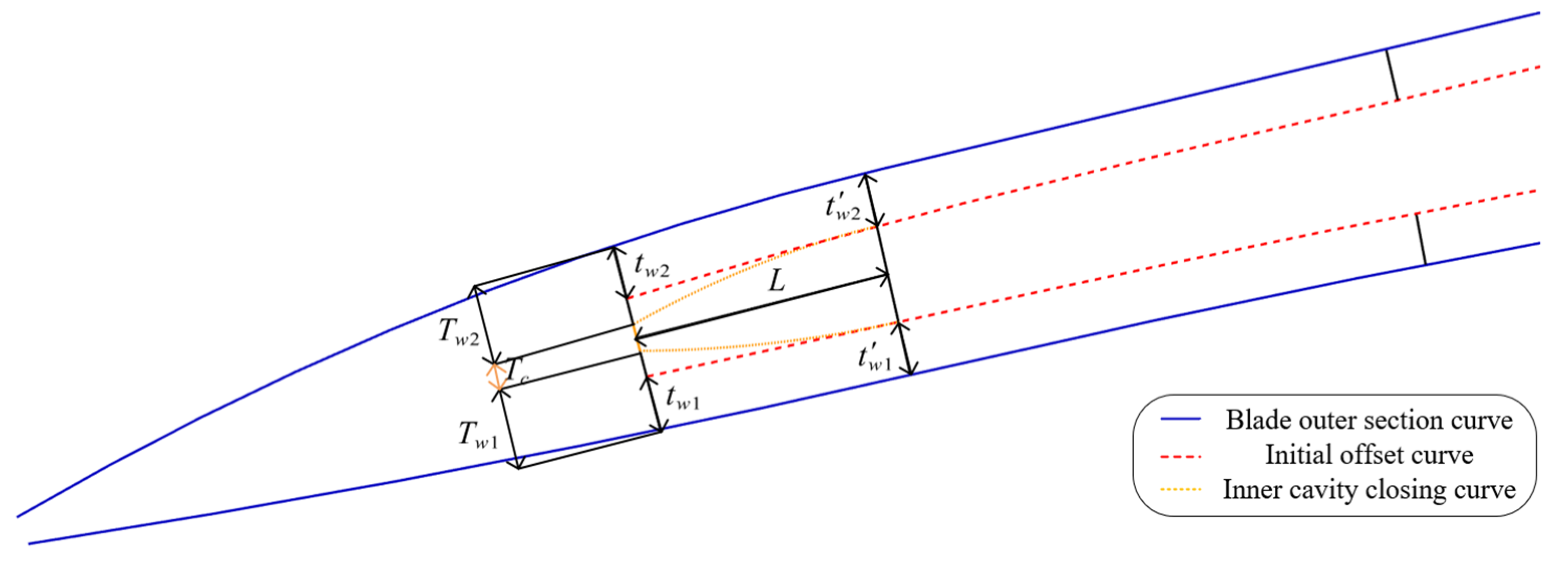
In addition, the higher requirements for wall thickness reduction in the hollow fan blade also bring challenges to the cavity closing design of the hollow structure. If the cavity closing length is too long, a narrow cavity gap will be generated, which will cause micro-motion wear during application. Therefore, for a thin-walled hollow blade, the cavity boundary needs to rapidly increase the wall thickness to complete the cavity closing. In response to the variable wall thickness and rapid cavity closing design requirements of the hollow fan blade, this paper proposes a cavity cross-section curve design method that combines a three-dimensional curve non-equidistant offset and cavity closing design. The specific process is shown in
Figure 8.
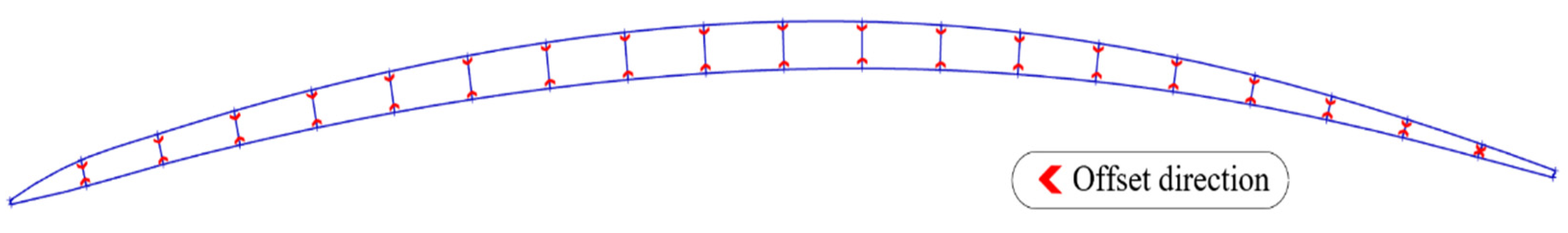
The base curve, offset direction, and offset distance are first determined based on the design parameters: The base curve is the outer shape curve of the cavity part, which is obtained by cutting the outer shape cross-section curve according to the solid part length of the leading and trailing edges. The offset direction is determined by the corresponding relationship between the base curves of the pressure and suction side, that is, the vector direction of the line connecting the corresponding points between the two curves is the offset direction at that location, as shown in
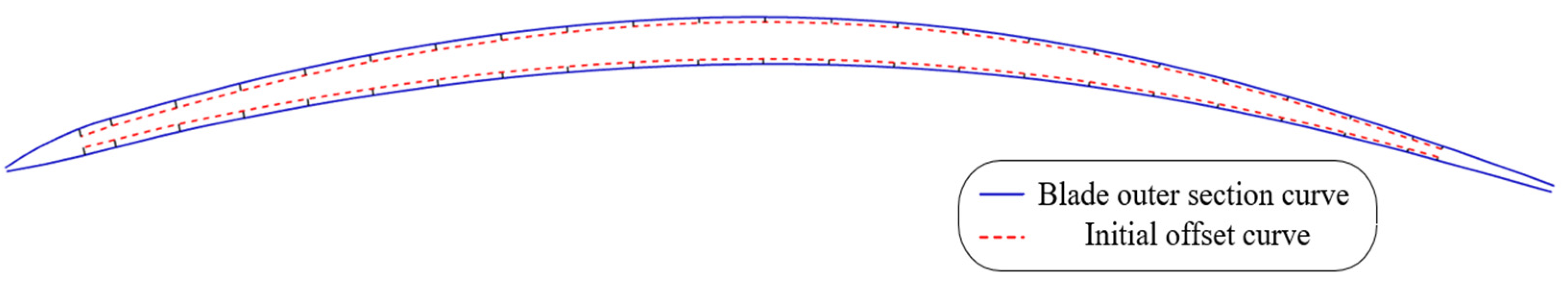
Figure 9. The offset distance is determined based on the wall plate thickness design parameter. Since this parameter changes along both the span and chord directions, the offset distance at each point is obtained through position interpolation. This paper adopts a non-equidistant offset method based on sampling fitting to obtain the initial design of the inner cavity curves. The sampling density is determined by the design accuracy, and the outer shape curves of the pressure and suction sides are offset according to the above-mentioned offset directions and offset distances, as shown in
Figure 10. However, since the given wall plate thickness variation parameters are difficult to accurately express the shape of the cavity closing parts and narrow the cavity width to the core plate thickness, the initial inner cavity curves cannot meet the shape characteristics of the wall plate thickness rapidly increasing in the cavity closing parts.
Therefore, this paper proposes a cavity closing design method for the inner cavity curves of the hollow blade, as shown in
Figure 11. The inner cavity boundary is narrowed to the core plate thickness
, while keeping the pressure and suction wall plate thickness ratio unchanged, that is Equation (1).
where
are the initial design values of the pressure and suction wall plate thickness at the inner cavity boundary,
are the pressure and suction wall plate thickness values that meet the requirements of the cavity closing to core plate thickness, and
is the pressure and suction wall plate thickness ratio.
In order to avoid the formation of a long and narrow space at the cavity boundary and ensure a smooth cavity closing shape, the ratio of the cavity closing length to the wall plate thickness change of the cavity closing part is used as the parameter to determine the starting point of the cavity closing part, and Equation (2) is obtained:
where
is the cavity closing length,
is the wall plate thickness change of the cavity closing part, and
is the proportional constant. Since the wall plate thickness of the initial design cavity curves in the cavity closing part is approximately unchanged, the wall plate thickness
at the boundary of the initial design is used to replace the wall plate thickness
at the starting point of the cavity closing part. Equation (3) is then obtained:
And because
, we obtain Equation (4):
where
is the cavity closing proportional constant, which controls the ratio of the cavity closing length to the wall plate thickness change. The larger the proportional coefficient
is, the longer the cavity closing length is, the slower the wall thickness changes at the cavity closing part, and the cavity closing shape becomes narrow and long; the smaller
is, the shorter the cavity closing length is, the more rapid the wall thickness changes at the cavity closing part, and the cavity closing shape becomes unsmooth. It is actually determined by the blade thickness reduction requirements, and in this paper, a value of 10 is taken based on the prior blade design experience.
Based on the cavity closing judgment rules, the starting positions of the cavity closing part can be determined. The initial offset curves can be smoothly extended from this position to the cavity boundary points at the leading and trailing edges, and finally the complete inner cavity curves are obtained, as shown in
Figure 12.
4.2. Design Method of Cross-Section Corrugation Structure
The core plate supporting cavity of the three-layer hollow fan blade designed in this paper is in the shape of the corrugated structure. Since the number and shape of the corrugations change along the blade span direction, it is necessary to design the core plate structure separately in each layer of the inner cavity cross-section designed above. Therefore, this paper proposes a parametric design method for the cross-section corrugation structure.
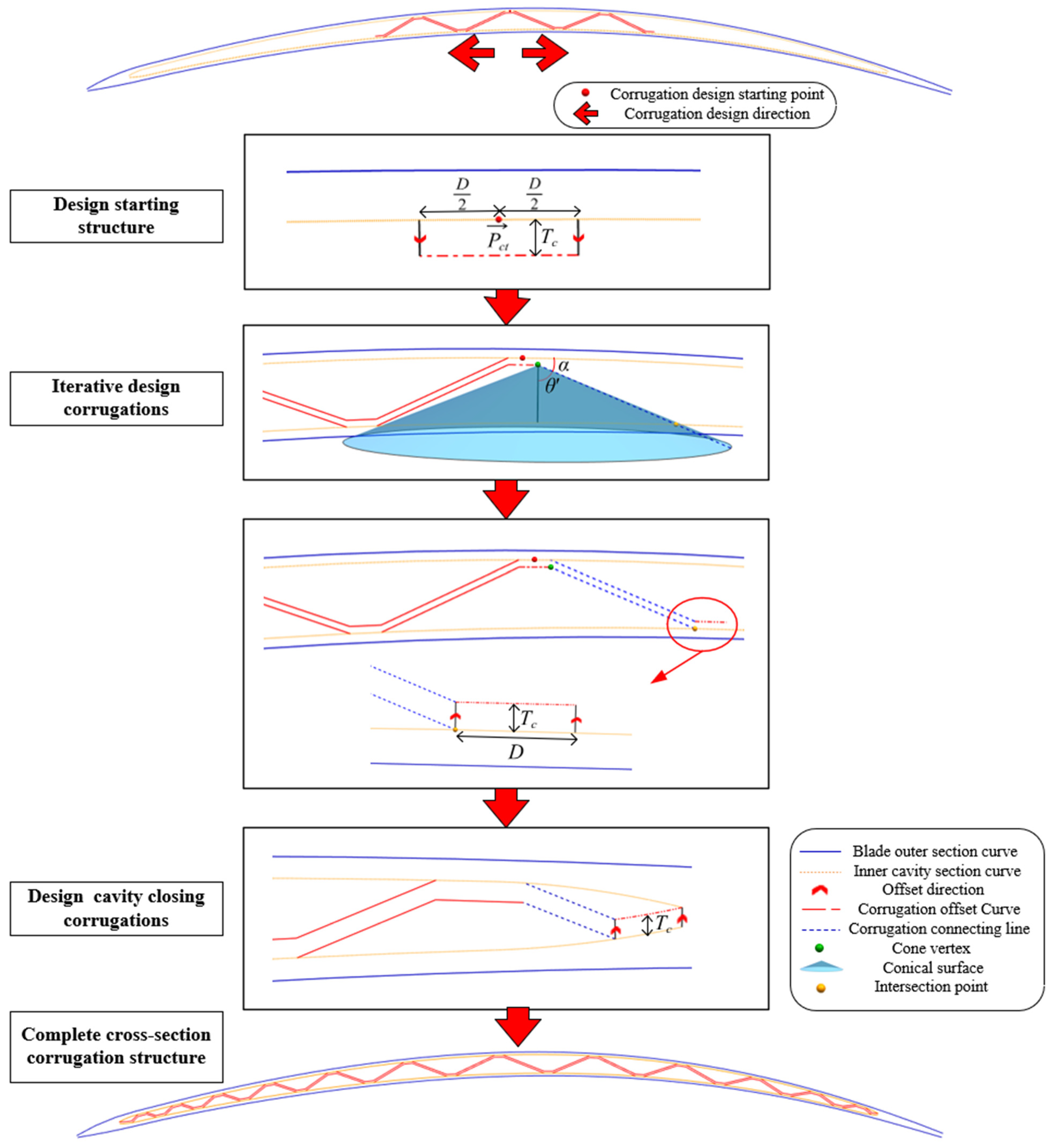
First of all, it is necessary to determine the design starting position of the corrugation structure in a cross-section. In order to maintain the balance of the number of corrugations distributed in the chord direction, this paper selects the intersection point of each inner cavity cross-section curve and the central ridge curve as the design starting position of the core plate structure in a single cross-section. Then, from this design starting point , driven by the corrugation design parameters—including diffusion bonding width, core plate thickness, corrugation angle, and cavity closing design parameters—corrugations are generated one by one along the chord direction to both sides of the leading and trailing edges.
The design method of the core plate structure in the cross-section proposed in this paper is as shown in
Figure 13. The steps are as follows:
Design the starting structure: According to the diffusion bonding length
, move
from the design starting point
along the inner cavity cross-section curve to both sides to intercept the inner cavity cross-section curve. Similar to
Section 4.1, the normal direction of corresponding connection lines of the pressure and suction inner cavity cross-section curves is used as the offset direction and the core plate thickness
as the offset distance, and the intercepted curve is offset toward the inner cavity to obtain the starting structure.
Iterative design corrugations on both sides: According to the experimental results of the diffusion bonding manufacturing process, maintaining the good manufacturing quality of the blade requires that corrugation angle parameter
, wall plate thickness
and core plate thickness
satisfy a corresponding relationship, that is Equation (5).
where
is the machining allowance of blade outer surface. And the design corrugation angle of the process optimal performance is obtained by interpolation of this equation. Since the wall plate thickness
of the advanced hollow blade changes in both the span and chord directions, and the core plate thickness
changes in the span direction, when designing the core plate structure in a single cross-section, each corrugation needs to be interpolated to calculate its process optimal performance angle
. The end point of the corrugation diffusion bonding part is taken as the vertex, and the extension line of the vertex along the offset direction is taken as the rotation axis. The set of straight lines that meet the specified angle requirements in three-dimensional space forms a conical surface, and this conical surface is constructed to intersect with the inner cavity cross-section curve on the opposite side to obtain the starting point of the next corrugation. The point is moved along the inner cavity cross-section curve by the diffusion bonding width
to intercept the curve. According to the same offset method as the starting structure, the intercepted curve is offset toward the inner cavity to obtain the next corrugation diffusion bonding part. The adjacent corrugations are connected to obtain the complete corrugation structure.
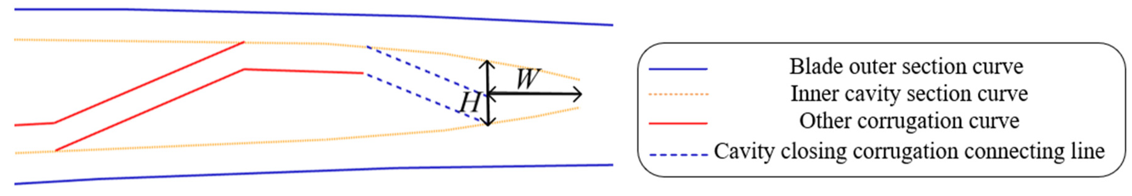
Design the cavity closing corrugations: In each design cross-section, according to the above method, the corrugations are generated one by one from the starting structure to both sides until the cavity closing constraint condition is met, and then the cavity closing corrugations are designed to obtain a complete corrugated structure in the design cross-section. The corrugation cavity closing constraints defined in this paper are as shown in
Figure 14, including the following:
1. Corrugation quantity constraint. Due to the performance requirements of the hollow fan blade, its ribs need to be complete along the span direction. Therefore, the number of corrugations in each cross-section cannot be increased from the blade tip to the blade root, that is, when the number of corrugations in a certain design cross-section reaches the number of corrugations in the upper cross-section, the corrugation structure cannot be added, and the cavity closing design needs to be performed.
2. Inner cavity spacing constraint. In order to avoid the shape of the cavity closing corrugations being too flat, when the distance between the inner cavity pressure and suction side is less than the set value, the corrugation structure will no longer be generated. Since the cavity closing corrugation shape is related to the core plate thickness , the setting of the spacing constraint value is proportional to the core plate thickness. Based on the design knowledge of the hollow blade, this paper takes the value as the inner cavity spacing constraint value at the cavity closing position, that is, when , the cavity closing corrugation design is performed.
3. Chordwise distance constraint. The chordwise distance constraint value is proportional to the corrugation diffusion bonding width . Due to the manufacturing process limitations, this paper takes as the judgment value, that is, when , the corrugation structure is designed for cavity closing.
The design method of cavity closing corrugations is as follows: the conical surface is first constructed according to the end point of the previous corrugation, normal direction at that position and specified angle. The starting point of cavity closing corrugation is obtained by the intersection point with the inner cavity cross-section curve on the other side. The inner cavity curve between this point and the boundary point is intercepted and offset inward to obtain the bonding part of the cavity closing corrugation. The adjacent corrugations are connected to obtain the complete cross-section corrugation structure, as shown in
Figure 13.
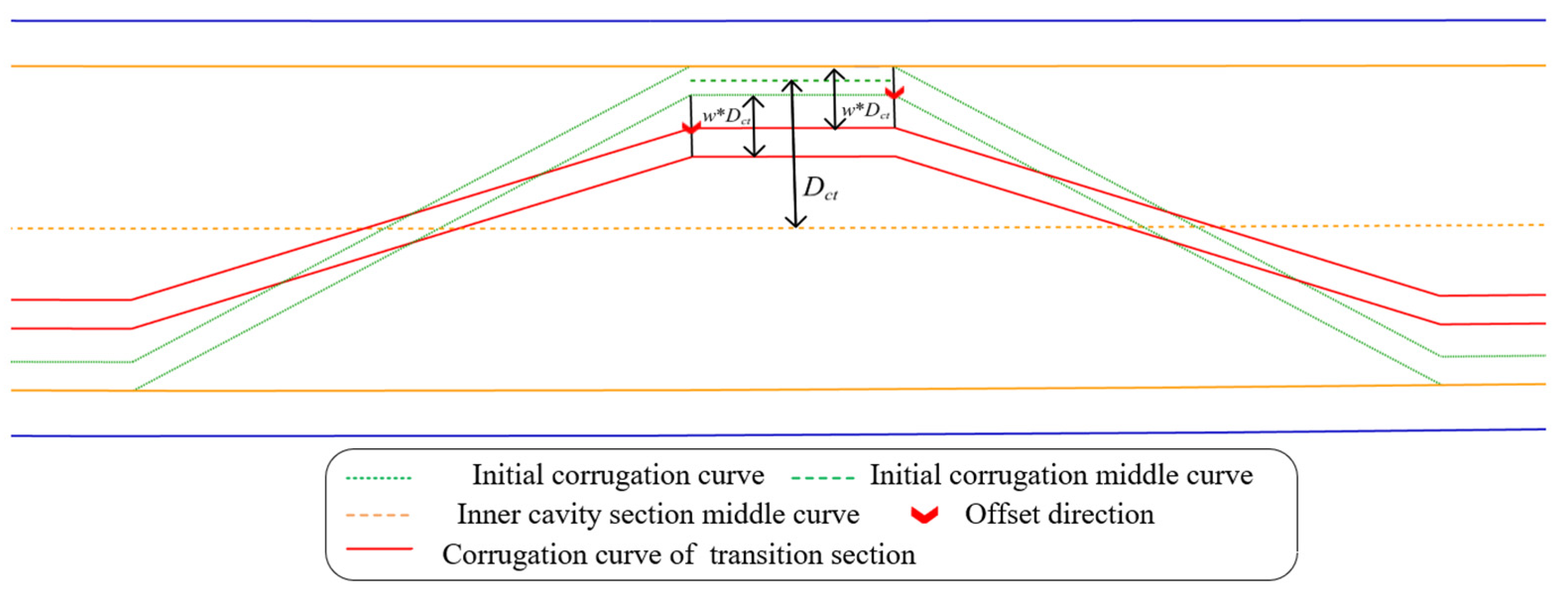
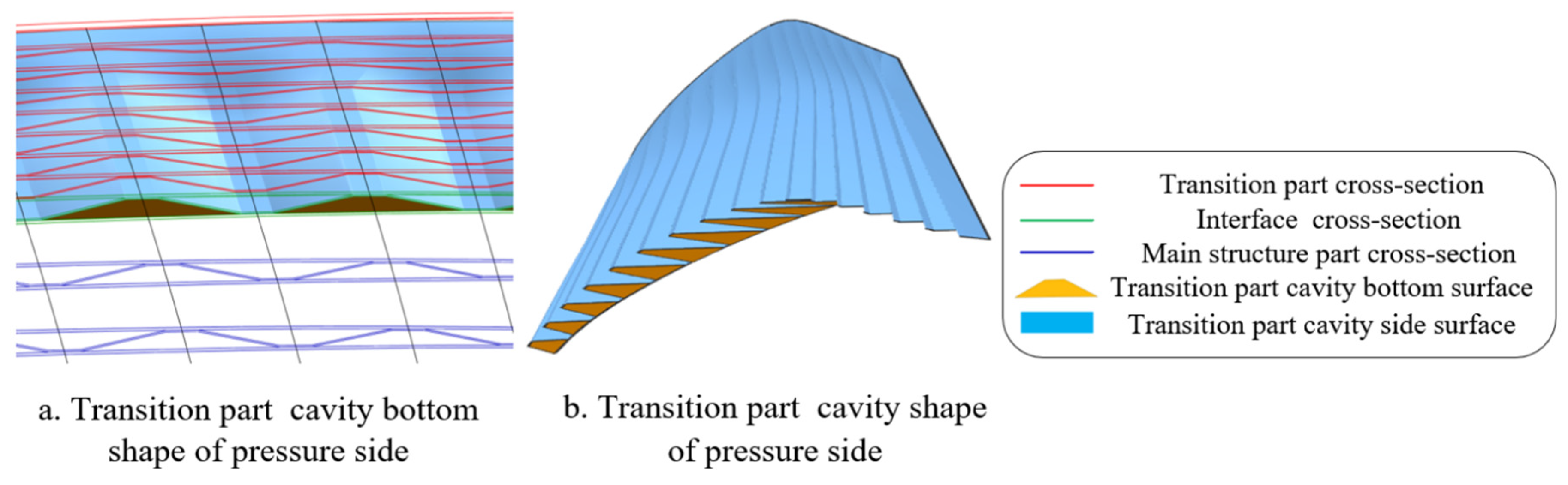
In order to improve the application performance, the tip of the advanced hollow blade is designed with an air intake transition part, and the air can flow along the chord direction in this part. Corresponding to the geometric structure design, there is a gap between the wall plate and the core plate within a certain distance below the tip boundary of the cavity. The geometric shape of the core plate in this transition part is shown in
Figure 15, and its characteristics include the following: 1. At the blade tip boundary of the cavity, the core plate and the wall plate are fitted to form a solid shape. 2. From the blade tip boundary of the cavity along the span direction downward, the core plate gradually changes from a smooth plate shape to a twisted corrugated shape. 3. From the blade tip boundary of the cavity along the span direction downward, the core plate gradually transitions from not fitting the wall plate to the corrugated shape that bonds the wall plate.
In view of the geometric characteristics of the core plate of the transition part, this paper proposes a design method for the corrugation structure of the transition part. According to the aforementioned method, the corrugation structure that bonds the wall plate is initially designed in the design cross-section, and then the curves of the corrugation bonding part are offset to the inner cavity, and each corrugation is reconnected to obtain the transition cross-section core plate structure. The offset direction still uses the normal direction of the connection lines corresponding to the pressure and suction side inner cavity cross-section curves. The offset distance is determined based on the span distance of the design cross-section from the blade cavity tip boundary. The specific calculation process is as follows: The middle curve of the pressure and suction side inner cavity cross-section curves and the center curve of the corrugation bonding part are first constructed. For a single corrugation, the projected distance between the center curve of the bonding part and the middle curve of the inner cavity in the offset direction is the distance
offset to the center of the inner cavity. Then, the spanwise distance
of the design cross-section from the blade cavity tip boundary and its proportional position in the air intake transition part are calculated, that is Equation (6).
is the spanwise length of the transition part. When
, that is, at the blade cavity tip boundary, the proportional position
; when
, that is, at the bottom boundary of the transition part, the proportional position
. In order to ensure that the core plate gradually transforms into a bonding wall plate from the cavity tip in the transition part, the inward offset distance of the transition corrugation is
, that is, when the design cross-section is located at the blade cavity tip boundary, it is completely offset to the center of the inner cavity, and the core plate is a smooth plate, while at the bottom boundary of the transition part, no offset is performed, and the core plate forms a completely twisted corrugated structure.
Figure 16 and
Figure 17 show the offset process and structural shape of the transition part corrugation.
4.3. Rib Smoothing Optimization Method
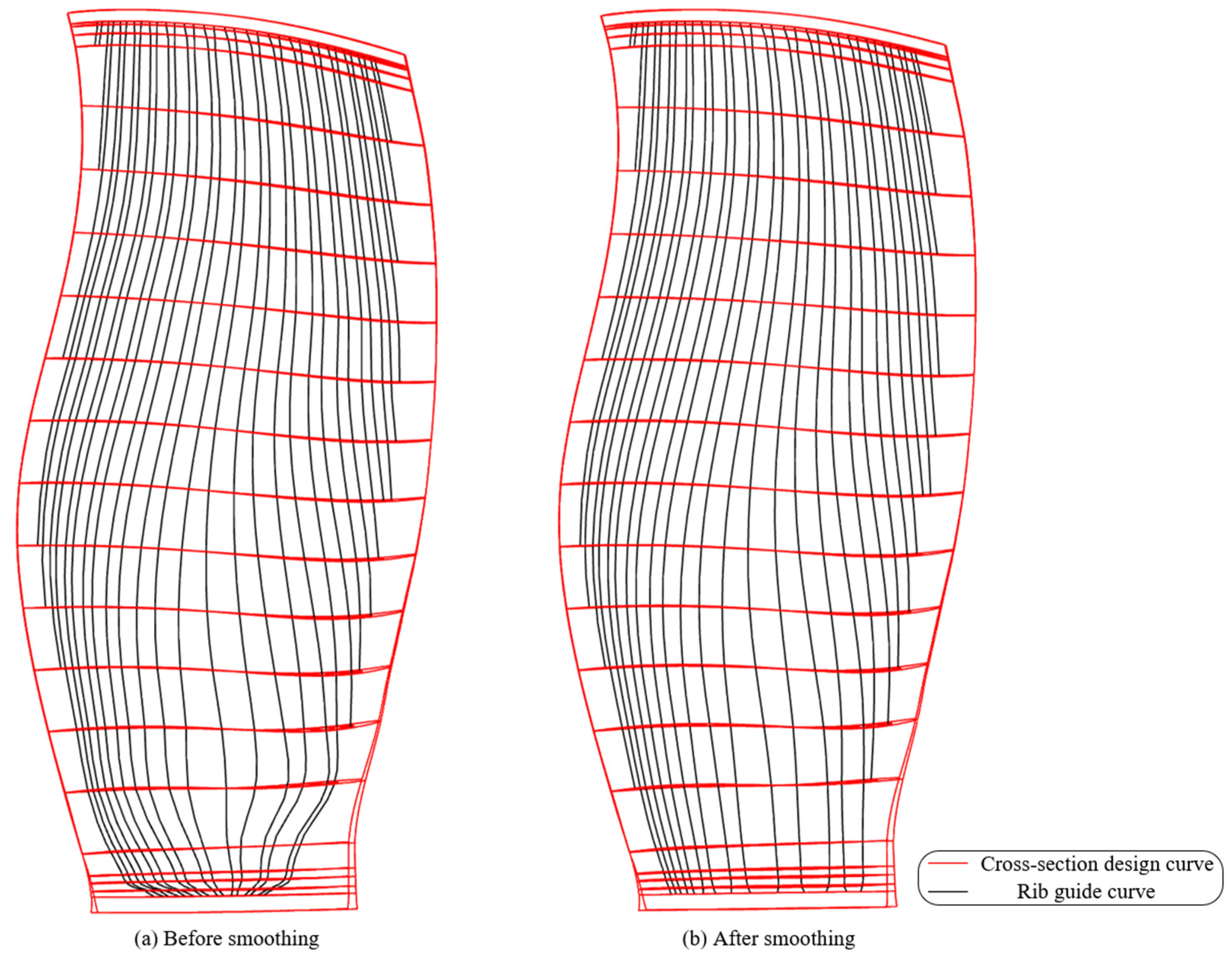
The three-layer hollow fan blade designed in this paper has a core plate corrugated cavity structure that forms multiple groups of ribs and hollow channels along the span direction. In order to avoid stress concentration and meet the strength and performance requirements, it is necessary to ensure that the ribs and hollow channels cannot be twisted during design and are as smooth as possible along the span. Based on the hollow blade cross-section wireframe structure designed in this paper, the center points of the corresponding corrugations in the span direction in each cross-section are connected and fitted to obtain multiple span guide curves. These guide curves represent the spanwise trend of the ribs and hollow channels, as shown in
Figure 18a. When designing the core plate structure in the cross-section, the optimal angle under the manufacturing process constraints was selected to design the corrugation structure, without considering the spanwise smoothness of the ribs and channels in the strength performance constraints. The span guide curves of the corrugation designed in this way are twisted, especially in the area where the wall plate thickness changes greatly; the twist is serious, so further smoothing optimization is required.
At present, there are many definitions of the smoothness of curves, and the commonly used ones are curvature, curvature change, and curve energy. In this paper, on the basis of eliminating the kink points of the guide curves, the curve strain energy as the smoothing standard and the curve smoothing algorithm based on the minimum energy are used to optimize the strain energy of the rib guide curves to be the minimum, so as to improve the mechanical properties of the hollow corrugated structure.
The curve strain energy is an energy function defined by assigning mechanical properties to the curve, which is usually the sum of the squares of the curvature of the curve, and the expression is given in Equation (7):
where
is the curvature of the curve. The existing curve smoothing algorithm based on the minimum energy method generally uses the total energy function combining the curve strain energy and the potential energy of restoring the original shape as the smoothing index to ensure that when the total energy is minimized, the curve can maintain its original shape while being smoothed. The expression is given in Equation (8).
where
is the smoothing coefficient,
is the curvature of the smoothed curve,
is the deviation coefficient from the original curve,
is the original curve,
is the smoothed curve, and the smoothing optimization of the curve is completed by minimizing the total energy
. The values of
and
can coordinate the smoothness and deviation of the curve. The larger
is, the greater the proportion of curve strain energy in the total energy, the better the smoothness after optimization, but the greater the deviation from the original curve; the larger
is, the greater the proportion of potential energy in the total energy, the lower the deviation from the original curve after optimization, but the worse the smoothing effect. In order to simplify the energy minimization process, the curve is discretized, and the integral of the curve deviation values is simplified to the sum of the deviation values of the discrete points, then the total energy expression is simplified as Equation (9):
where
is the curve data point after smoothing, and
is the data point of the original curve. Based on the hollow blade wireframe structure designed in this paper, the spanwise guide curves of ribs are discretized according to the design cross-section position, and the corrugation position points are selected as the sampling points for smoothing optimization, that is, the cross-section corrugation positions are adjusted to smooth and optimize the rib curves. In the manufacturing process constraints of the hollow blade, compared with the moving distances of the corrugation position points, more attention is paid to the change of the corrugation angles after moving position points. The corrugation angle should keep the optimal angle of the process requirements adopted by the above design as much as possible. Therefore, this paper modifies the potential energy term in the total energy of the curve to the corresponding corrugation angle change term, and the total energy expression is modified as Equation (10):
where
is the angle change proportion coefficient,
is the angle of the corrugation which the guide curve passes through in cross-section
, and
is the optimal angle that meets the process requirements. In addition to recommending the optimal angle, the existing manufacturing process also has a series of constraints on the corrugation angle, as in Equation (11):
where
is the corrugation angle corresponding to the minimum thickness of the core plate after forming,
is the angle difference between the adjacent corrugations in the same cross-section,
is the maximum value of the adjacent corrugation angle difference constrained by the supporting symmetry of the corrugation structure,
and
are the maximum and minimum angles in the same cross-section, and
is the maximum angle range limited by the manufacturing process.
Therefore, the problem of smoothing the rib guide curves is transformed into an optimization problem of adjusting the position of corrugations in the design cross-section and minimizing the energy under the process constraints of the corrugation angle . The optimization problem is expressed as follows:
Find: ;
Minimize: ;
Subject to:
This optimization problem is concise and clear, and the gradient descent method is used to minimize
. In this paper, the smoothing coefficient is 0.8 and the angle change coefficient is 0.2. The optimization process terminates when either of the following criteria is met: the relative change in the energy function
between consecutive iterations is less than
, or the Euclidean norm of the gradient is below
. Additionally, a maximum of 20,000 iterations is set to ensure termination in case the convergence criteria are not strictly satisfied. The computational complexity of each iteration is
, where
is the number of corrugations. The shape of the spanwise guide curves after smoothing obtained through iterative calculation is shown in
Figure 18b, in which the guide curve kinking is eliminated, the curvature changes evenly, the corrugation angles meet the requirements, and the result meets the performance and process constraints in the structural design.
4.4. Hollow Blade Wireframe Densification and Solid Modeling Method
The hollow blade geometric structure design method proposed in this paper effectively realizes the generation of a hollow blade wireframe structure driven by design parameters and knowledge, based on the blade’s outer free-form surfaces. However, the position and number of the selected design cross-sections have a lot of influence on the design efficiency and quality. Although increasing the number of design cross-sections can improve the design accuracy and refine the hollow blade structural form, it will increase the time consumption of geometric calculations and seriously reduce the efficiency of design and optimization adjustment; while reducing the number of design cross-sections improves the design efficiency, it will reduce the design accuracy. When the number is too small, it is impossible to fully express the hollow blade structure. For example, when the chordwise number of corrugation changes, too few design cross-sections cannot accurately express the position of the number change, which brings difficulties to subsequent solid modeling.
Therefore, this paper proposes a cross-section densification method for the hollow blade wireframe structure. The key position cross-sections are first selected for hollow structure design and optimization adjustment, and then the number of cross-sections is increased by interpolation on the wireframe structure to obtain a more complete wireframe structure. The interpolation densification method of the section is described in detail below.
The position of the added cross-sections is obtained by linear interpolation between the spanwise coordinates of the initial design cross-sections, and the interpolated coordinates are projected along the blade thickness direction to the pressure and suction outer surfaces to obtain the outer curves of the added cross-sections. The outer curves of the densified cross-sections are offset according to the inner cavity cross-section curve design method in
Section 4.1 to obtain the inner cavity cross-section curves of the densified cross-sections. The corrugations in the densified cross-sections are designed based on the spanwise smoothing rib guide curves. This paper proposes a spanwise smooth corrugation structure densification method, as shown in
Figure 19.
The initial hollow blade wireframe structure is first smoothed and optimized, and some guide curves need to be extended, because the beginning and end points of the guide curves are all in the initial design cross-sections, which cannot meet the integrity of the corrugation structure after interpolation and densification. The spanwise guide curves are smoothly extended along the end tangent vector to the cavity closing position of the inner cavity curves of the densified cross-section. The intersection points of the smooth guide curves and the densified inner cavity cross-section curves are used as the center point of each corrugation. The center point is moved 1/2D to both sides along the inner cavity cross-section curves to intercept the curve and offset it towards the inner cavity. In the same way, each corrugation diffusion bonding part of the entire cross-section is constructed and connected adjacently. The cavity closing corrugations are connected with the boundary points of the inner cavity curves to obtain a complete densified cross-section corrugation structure. Then, the angles of the densified corrugations are checked and corrected based on constraints. This method not only avoids kinks in the corrugation structure ribs but also quickly meets the process constraints of hollow blade design by checking and correcting the angles of a small number of corrugations.
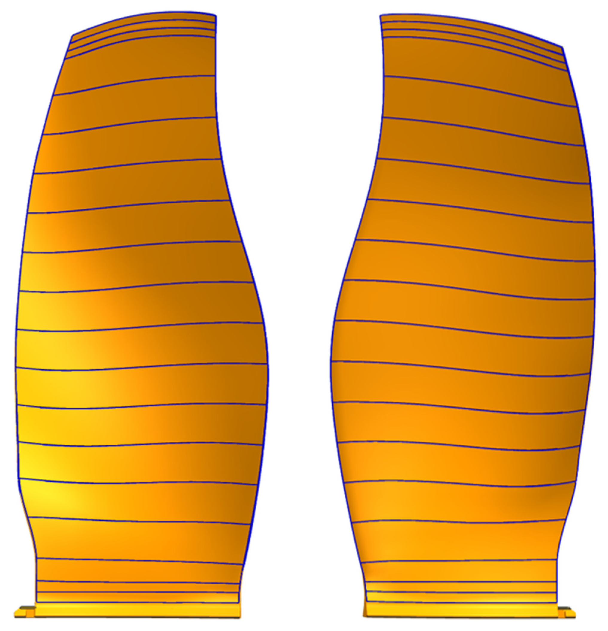
Since the geometric structure design within the densified cross-section is mainly obtained by the interpolation method, the geometric calculation time is much reduced, so increasing the number of densified cross-sections will not significantly increase the calculation time. Additionally, the designed hollow blade wireframe structure can assist in the subsequent meshing for finite element analysis, for instance, 2D meshing can be executed within the wireframe cross-sections and then connected to obtain the 3D finite element mesh of the blade. Therefore, the number of densified cross-sections can be set according to the required mesh size of the finite element analysis. In this paper, the number of densified cross-sections is set to 200 layers to ensure that the cross-section distance is within 5 mm. The final structural design result of a certain type of hollow blade with 200 layers of cross-sections is shown in
Figure 19d.
After the above-mentioned inner cavity cross-section curve design, cross-section corrugation structure design, rib smoothing optimization, and cross-section densification process, the densified cross-section wireframe structure model of the smooth hollow blade is obtained, as shown in
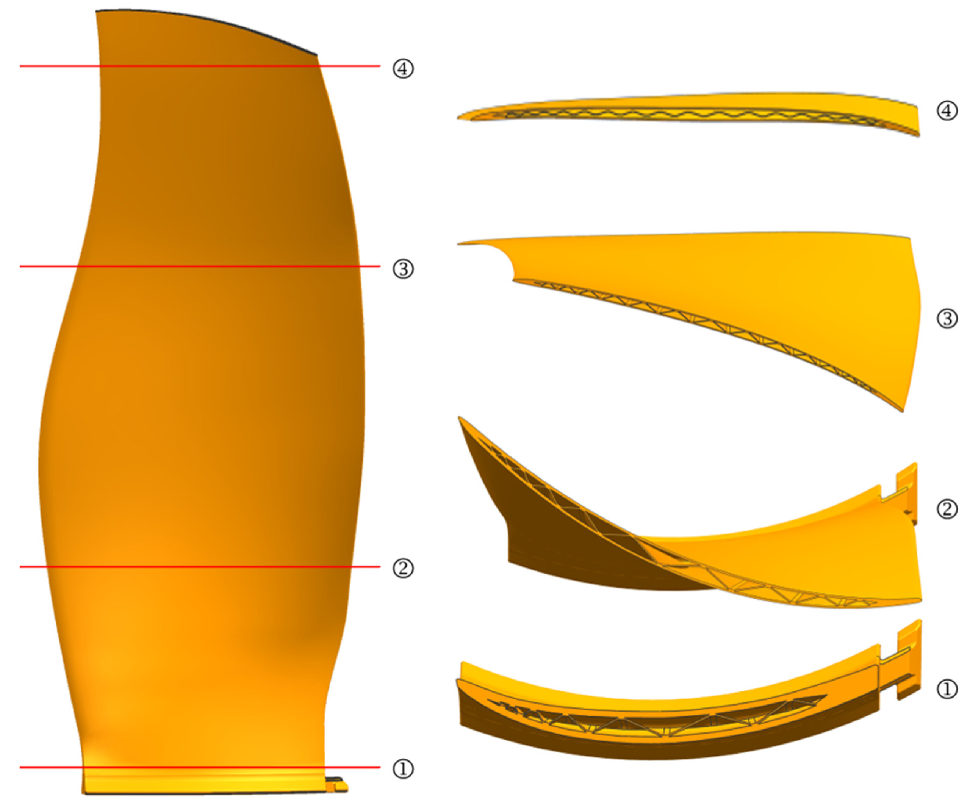
Figure 19d. Although the wireframe structure model can be directly related to the design parameters, which brings convenience to the design and optimization adjustment, and can also quickly realize the finite element meshing, it lacks structural integrity and cannot completely replace the solid model. Therefore, it is still necessary to create a solid model based on the hollow blade wireframe structure model. Since the outer surfaces of the hollow blade remain consistent with the original solid blade, only the hollow structure is added inside; thus, this paper models the hollow blade by subtracting the cavity part from the solid blade, which reduces the modeling process of the outer surfaces and improves efficiency. The hollow blade solid modeling method proposed in this paper is as follows: According to the structural characteristics of the hollow blade, the cavity area is divided into two parts along the span direction, the main structural part and the transition part, and the cavity channel entities are constructed separately. The core plate of the main structure part is diffusely bonded to support the wall plate, and its cavity geometric characteristic is that each cavity channel is not connected to other channels and exists independently. So, it is necessary to perform separate solid modeling on each cavity channel, as shown in
Figure 20.
The air intake transition part is located at a distance below the blade tip. Its corrugation structure does not fit the wall plate, and its corrugated cavities are connected to each other. Therefore, it is necessary to construct two cavity solid models on the pressure side and the suction side, respectively. The modeling process is shown in
Figure 21. Its bottom surfaces are obtained by constructing bounded surfaces in the interface between the transition part and the main structure part. The two side surfaces are, respectively, the wall plate inner cavity surface and the corrugated cavity surface. The wall plate inner cavity surface is generated by smoothly connecting the inner cavity cross-section curves. The corrugated cavity surface is composed of multiple connected surfaces and is generated by connecting the corresponding characteristic curves of each corrugation smoothly. The top is a closed shape of the side surfaces, and the bottom surfaces and side surfaces are sewn to obtain the transition part cavity entities.
A Boolean sum operation is performed on the cavity entities of the two parts to obtain the complete cavity solid model, and then the original solid blade model is used to Boolean subtract the cavity solid model to complete the modeling of the hollow blade solid model, and the design result of a certain type of hollow blade is shown in
Figure 22.
5. System Implementation and Future Extensions
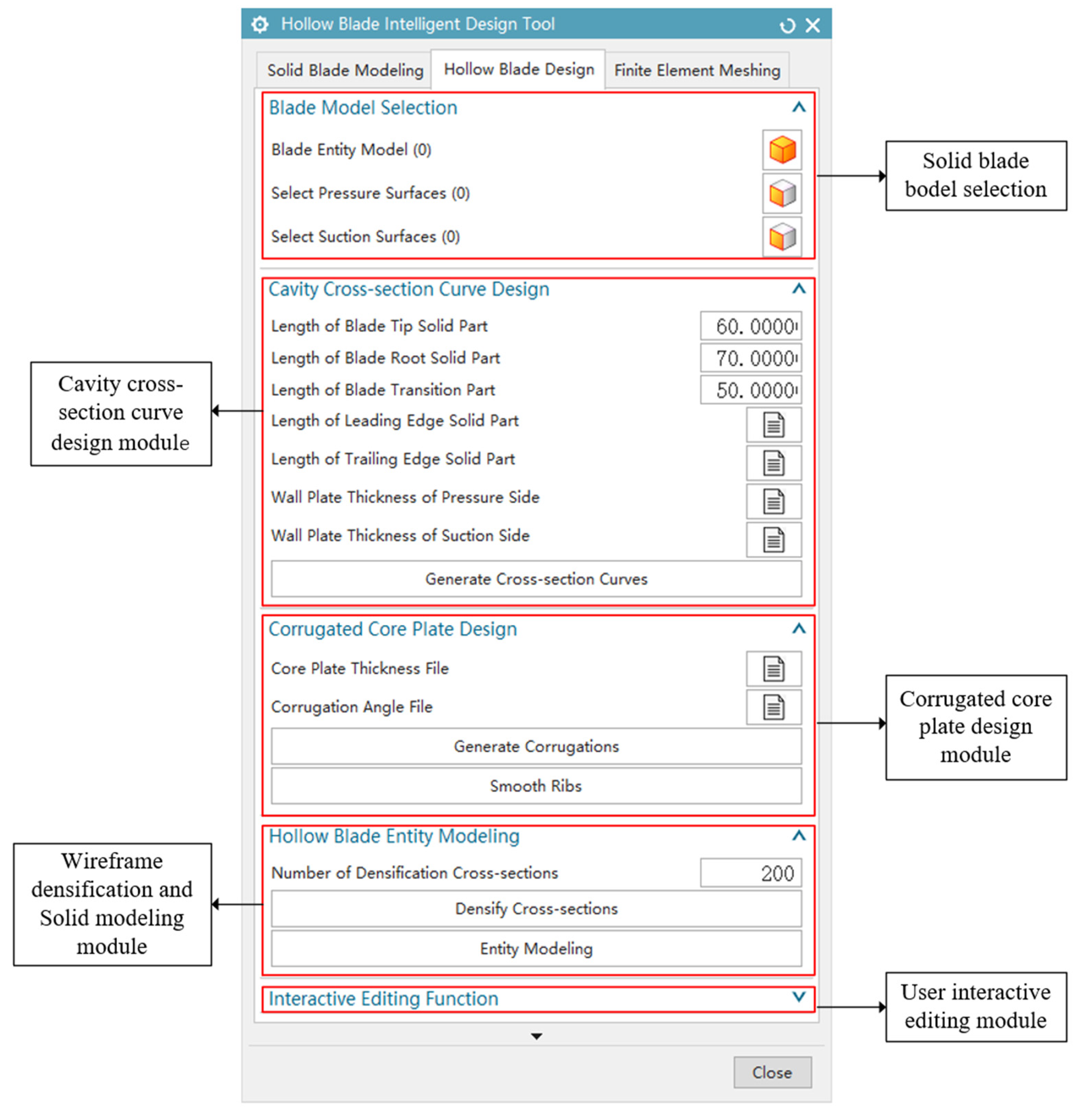
Based on the aforementioned intelligent design process and method of the three-layer hollow fan blade, this paper researched and developed an intelligent design system for the three-layer hollow fan blade. The system uses the C/C++ programming language for secondary development based on the Siemens NX11.0 geometry platform, in the Visual Studio 2019 development environment. By calling design knowledge and design parameters and combining interface functions, the intelligent design of the hollow blade is realized. The system’s main interface is shown in
Figure 23.
The system automatically realizes the design of the hollow blade structure within the solid blade model by calling the design knowledge files and the design parameter files and obtains the hollow blade model that meets the process constraints and design requirements. The main functions of the system include inner cavity cross-section curve generation, corrugation structure generation, cross-section densification, and solid modeling, which, respectively, realize the steps of the intelligent design process of the hollow blade in this paper. This system visually displays the design results of each step for easy inspection and modification. At the same time, in order to improve the freedom degree in the intelligent design of the hollow blade, this system has developed the user-defined editing function, which supports users to interactively modify the wall plate thickness and corrugation angle.
The structural design of a certain type of hollow blade was completed using this system, and the design result is shown in
Figure 22. This system has been put into actual production application, verifying the feasibility of the intelligent design method for the three-layer hollow fan blade proposed in this paper. The system was tested on a workstation equipped with an Intel (Santa Clara, CA, USA) Core i9-10900 processor (10 cores, 2.8 GHz), 32 GB of RAM, and an AMD (Santa Clara, CA, USA) Radeon RX 640 GPU. It took 22 min and 37 s to design the hollow blade with 15 layers of initial design cross-sections (each section includes six wall thickness parameters, two solid part length parameters, and one core thickness parameter) and 200 layers of densified cross-sections, while it would take engineers more than a week to complete this work using traditional methods. The comparison demonstrates that the intelligent design system for the three-layer hollow fan blade proposed in this paper significantly improves the design efficiency.
The wireframe structure model and solid model of the hollow blade automatically generated by this intelligent design system can be used for subsequent performance analysis; in particular, the wireframe model retains a large amount of geometric structure information, which can assist in the meshing for finite element analysis. Therefore, the subsequent improvement goals of the intelligent design system include the following:
Automatically generate a finite element mesh based on the geometric model of the hollow blade and integrate simulation analysis software such as ANSYS (version 2024) to analyze the static strength and fatigue strength of the designed hollow blade.
Based on the process automation advantage of the hollow blade intelligent design system developed in this paper, integrate advanced optimization algorithms, with the goal of improving strength performance, and automatically and rapidly optimize the hollow blade design parameters such as the wall thickness, solid part length, and corrugation angle.
In the future, CFD simulation and existing aerodynamic performance optimization methods can also be integrated in this system to optimize the aerodynamic shape of the hollow blade. Develop a multi-objective integrated optimization system that meets the requirements of aerodynamic performance, static strength performance, fatigue performance, and light weight, so as to achieve the integrated optimization of aerodynamic shape and internal structure of the hollow blade.
6. Conclusions
In this paper, based on the design and manufacturing knowledge of the three-layer hollow fan blade and geometric algorithms such as complex curve offset and smoothing, an intelligent design method for the complex geometric structure of the three-layer hollow fan blade is proposed, and an intelligent design system for three-layer hollow fan blades is developed. The method has the following characteristics:
A designing method for the inner cavity cross-section curve of hollow blade wall plates is proposed. By leveraging the three-dimensional non-equidistant offset algorithm and cavity closing adjustment strategy, this method enables the rapid generation of the blade wall plate wireframe structure, ensuring compliance with the variable wall plate thickness requirements and cavity closing constraints of advanced hollow fan blades.
An innovative parameter design method for the corrugation structure in the cross-section is proposed, which is the key geometric algorithm for the design of hollow blade core plates. By constructing the conical surface with the design angle, corrugations in the designed cross-section one by one are automatically generated, and the rapid parametric design of the corrugated core plate structure is achieved.
A spanwise rib smoothing optimization method based on the energy minimization is proposed. The corrugation angle change term is added to the total energy equation to ensure that angle constraints of the manufacturing process are met, and the gradient descent method is used to minimize the energy of the rib guide curves to obtain the spanwise smooth hollow blade wireframe structure.
A cross-section densification method by the smooth wireframe structure interpolation is proposed to improve the design efficiency and geometric expression. And by smoothly connecting the blade wireframe structure, the rapid solid modeling of the hollow blade is achieved.
A three-layer hollow fan blade intelligent design system is developed. This system is seamlessly integrated with NX software and enables the automated design and three-dimensional modeling of complex geometric structure of the hollow blade under complex aerodynamic shape and a large number of design and process constraints. Its application in actual blade design has demonstrated significant improvements in efficiency.
In addition, the wireframe structure model of the hollow blade designed by this method can be used for subsequent finite element meshing. The next step of this paper is to simulate and optimize the geometric structure of the hollow blade based on the automatic design, modeling, and meshing functions of the intelligent design system, combined with relevant optimization algorithms, to improve the static strength and fatigue performance of the hollow blade. In the future, aerodynamic performance optimization methods can also be integrated into this intelligent design system to achieve integrated optimization of aerodynamic shape and internal structure of the hollow blade.


