Article

Simulations and Analyses of the Influence of a Vacuum Back-Pressure Environment on Laser Ablation Thrusters

State Key Laboratory of Advanced Space Propulsion, Department of Aerospace Science and Technology, Space Engineering University, Beijing 101416, China
*
Authors to whom correspondence should be addressed.
Aerospace 2025, 12(5), 445; https://doi.org/10.3390/aerospace12050445
Submission received: 25 January 2025 / Revised: 10 May 2025 / Accepted: 15 May 2025 / Published: 19 May 2025
(This article belongs to the Special Issue Laser Propulsion Science and Technology (2nd Edition))

Abstract

:
The study of thruster plume flow fields can yield a series of thruster performance parameters such as thrust effect, spacecraft plume contamination, etc., which is of great significance for thruster development. The paper presents a physical simulation model of a laser thruster under a vacuum back-pressure environment. Through the finite difference method and the Direct Simulation Monte Carlo (DSMC) calculation method, based on the actual laser ablation thruster structure and working mode, the changes in the flow-field distribution in the laser thruster plume under different vacuum back-pressure conditions are obtained. The influence of different vacuum back-pressure conditions on the plume density, pressure, temperature, and velocity field of the thruster was verified through physical experiments, and the evolution of the plume flow field during the laser ablation of a polyamide glycidyl ether (GAP) solid target material was analyzed in detail. The simulation results are in good agreement with the test results, and the deviation between the simulated data and the test data from 0 to 3000 ns is less than 10.4%. This study presents a foundation for a prediction model of laser ablation thrusters under vacuum environments and provides an important reference for ground tests and in-orbit applications of satellite laser propulsion systems.

1. Introduction

Laser propulsion is a new concept propulsion technology that utilizes a high-energy laser to heat the working medium, resulting in high-temperature gas thermal expansion working to generate thrust and propel the vehicle forward, holding promise for use in future aerospace propulsion applications [1,2]. Compared with traditional chemical [3,4] and cold gas [5,6] propulsion technology, it has the advantages of high specific impulse and propulsion efficiency. Additionally, due to the lightweight nature of the propulsion system, the payload can be increased (with a payload ratio of over 15%), greatly reducing launch costs [2,3,4,5,6,7,8]. Since 2000, China has made significant progress in the research of laser propulsion technology, and the demand for research projects related to the characteristics of laser thrusters has gradually increased (a “laser ablation thruster” is a type of laser thruster) [9,10,11,12,13]. However, there are many problems that need to be solved in the relevant technologies.
The flow fields of thrusters under vacuum back-pressure environments directly influence their working effect, service life, and pressure transfer effect [14]. The flow field under a vacuum back-pressure environment not only affects various characteristics of the thruster, but also impacts the aircraft load near the convection and solar array when the plume field is formed after the on-orbit thruster is ignited, influencing the mechanics, thermal load, charge accumulation, and surface contamination [14,15,16,17]. These effects will lead to the uncontrolled movement of the aircraft in orbit and damage to the sensitive optical elements carried by the solar array and the aircraft and have serious impacts on sensitive elements such as optical devices, thermal control coatings, and the surface of the solar wing of the spacecraft, leading to performance degradation and even the complete failure of a system or component. Therefore, increasing research attention is being paid to the flow fields of spacecraft thrusters under vacuum back-pressure environments.
At present, simulations of thruster flow fields under high-vacuum environments generally employ two calculation methods: continuous flow and molecular flow. For the pressure field, velocity field, and density field of spacecraft thrusters at high altitudes, the N-S equation and the Monte Carlo method are the basic simulation analysis methods [18,19,20,21,22]. When the flow field contains a continuum, transitional flow, or free molecules, coupled simulation using the DSMC method can be used to perform a comprehensive simulation analysis; moreover, the DSMC method can also be optimized more than a decoupled calculation [20,21,22]. Calculations and experiments regarding high-altitude flow fields have previously been conducted outside China; however, only limited research data are available in this area because the gas density in the backflow area is much smaller than that in the forward flow area, which makes simulation and testing difficult [23,24]. In China, research in this field is in its infancy [25,26]. Numerical simulation studies regarding the plume field of laser thrusters with transmission ablation modes are currently insufficient; however, numerical simulations involving laser thrusters have the advantages of shortening the traditional development cycle and reducing the cost of ground vacuum tests. Therefore, these types of studies can take the development of laser thrusters into a new stage of rapid advancement. This study establishes a physical model of laser thruster ignition under a vacuum back-pressure environment; carries out simulation and analysis of the flow field, alongside other experimental research to obtain important basic data; and lays a foundation for defining the influence law of the flow-field distribution in a working-state laser thruster using on-orbit verification and application.

2. Model Analysis of the Ignition Process of a Laser Thruster

2.1. Model of Laser Thruster Ignition

In the transmissive laser thruster mode, the target material is irradiated through the transparent layer, absorbs energy, and generates thrust in the sputtering process. The whole model is based on a one-dimensional theoretical model of shock propagation. In the laser micro-ablation process, the transparent layer is used as the bearing structure of the thrust and is not expected to be ablated or destroyed. In the actual design process, materials with good ablation resistance, light transmittance, and some impact resistance are usually used. Therefore, the transparent layer (constraint layer) is considered as a solid wall during modeling and does not exchange energy with other parts. As shown in Figure 1, the laser passes through the transparent layer (constraint layer), irradiates the target surface of the interlayer working medium, heats, melts, and gasifies the working medium at a certain depth, and further ionizes it to rapidly form a high-temperature, high-pressure plasma; at the same time, a shock wave forms that propagates into the working medium. The plasma continues to absorb the laser energy until the end of the laser pulse and expands rapidly outwards, compressing the target material until the remaining target material is pushed out entirely from the working medium target.
The ignition stage of a laser thruster is generally divided into the absorption stage, the target material detachment stage, and the jet burst stage. The absorption stage is when laser irradiation occurs; the energy is I(t)dt. The laser passes through the transparent layer with its energy attenuated by the blocking and absorption of the transparent layer. The target material absorbs the laser energy by λ times I(t)dt, where λ is the absorption efficiency coefficient. In this study, λ is taken to be 0.8. At this point, part of it is used for expansion work (PdL), and part of it is used to increase internal energy, so there is a conservation-of-energy relationship:
λ I t d t = P t d L + d E i t L
where P is the pressure, L is the pressure spatial distance, and Ei is the internal energy.
The target material detachment stage occurs when the pressure intensity of the compressed target material is less than that corresponding to the plastic deformation of the target material; the target material is released and detached from the transparent layer. In this process, the main consideration is the acceleration process of the remaining target, and the equation of motion is as follows:
m d 2 L t d 2 t = P t
where m is the target migration quality.
The jet burst stage is characterized by a short detachment time for the target material. At the moment of detachment, the target material and the high-temperature and high-pressure gas inside begin to jet and burst. High-energy particles with laser energy diffuse freely in the cosmic environment, forming a plume field during the jet process.

2.2. Simulation Analysis Method

First, the geometric model of a laser thruster is established based on the actual structure, and the structure is refined for the key positions for the analysis of the flow field to obtain the ignition geometric model of the laser thruster. Then, a physical model of ignition under the space vacuum environment (where the thruster is located) is built based on the location, material properties, mechanical properties, and thermal properties of the thruster. As the engine is axisymmetric, in order to simplify the model to cut down the calculation, the model is axially divided; the bottom of the model is set as the mirror plane. The schematic diagram of the model is shown in Figure 2.
Since the model of the laser thruster mechanism is relatively regular, the square grid division method is used. During laser ablation propulsion, the thruster nozzle consists of the inner wall of the target strip. It is not examined in detail in this study except when considering the evolution of the plume field outside the thruster. The mesh inside the nozzle is twice as dense as the mesh outside. The grid division is shown in Figure 3.
The pressure at the ignition position increases during the laser thruster operation, and the high-pressure fuel becomes ultra-low-pressure fuel, i.e., a vacuum, once it is injected into the vacuum environment of the universe. The gas flow state is different under different pressures, and the drastic pressure change is accompanied by a huge change in the flow state of the ejected particles. As pressure decreases from high to low, the gas flow transitions through three regimes: turbulent flow, viscous flow, and molecular flow. Correspondingly, the gas behavior shifts from macroscopic to microscopic in nature. In engines, a variety of flow states exist simultaneously, including macro and micro volumes; due to this complexity in the gas behavior, jet process calculations are difficult. Therefore, the first step in our study is to determine which gas flow state is present during the operation of the laser thruster. The flow state of the gas can be determined by the mean free path of the molecules.
D Z > 100 viscous   flow ; D Z < 1 molecular   flow ; 1 < D Z < 100 mixed   state
Here, D is the molecule diameter, and Z is the average distance of the free path. Through calculations, it is known that the vacuum back-pressure environment of the universe (where the laser thruster is located) is in the molecular flow state, and, after laser ablation, the high-temperature and high-pressure gas inside the instant material eruption is in the viscous flow, or even turbulent flow, state. Therefore, this study adopts N-S and DSMC coupling to analyze and calculate the flow field of the laser thruster ignition process. The N-S equations (Navier–Stokes) are the governing equations that describe the motion of a fluid, as follows:
u = 0
u t + ( u ) u = 1 ρ P + ν 2 u + F
where u is the velocity vector, t is the time, P is the pressure, v is the kinematic viscosity, and F is the volume force. The boundary conditions and mathematical description are as follows: (1) inlet—specify velocity distribution, u = uin (x, y); (2) outlet—pressure velocity gradient set to zero; (3) wall—fluid adheres to the wall, the normal velocity is zero, and the tangential velocity is zero; and (4) symmetric boundary—normal velocity is zero, and tangential velocity has no gradient. Numerical solutions are usually obtained by the finite volume method. The procedure is as follows: (1) spatial discretization—the convective term in the momentum equation is discretized by the upwind scheme, the diffusion term is discretized by the central difference, and the pressure phase needs to be interpolated at the grid faces; (2) temporal—the explicit method is the Euler method; and (3) solution sequence—assuming an initial pressure field, the momentum equation is solved to predict the velocity, the pressure correction equation is solved, the pressure is obtained, the velocity is updated, and the iteration repeats until convergence.
For an N particle distributed in physical space dV, the velocity distribution function is defined by the following equation:
f ( c ) d c = d N / N
where f(c) is the distribution function of molecules, c is the velocity space, and dN is the number of N particles within dc near point c in velocity space. Integrating Nf(c) over the entire velocity space leads to the following:
N f ( c ) d u d v d w = N
The Boltzmann equation has only one unknown variable, the distribution function of the molecule f, which is a function of time t, physical space (x, y, z), and velocity space (u, v, w). Boltzmann first derived the equations satisfied by the distribution function f in 1872, and the Boltzmann equation for a one-component gas is as follows:
n f t + c n f r + F n f c = + 0 4 π n 2 f * f 1 * f f 1 c r σ d Ω d c 1
where n is the molecular number density; σ is the differential collision cross-section; dΩ is the solid angle element; f * f 1 * is the distribution function of the two molecules after the collision; and f f 1 is the distribution function of the two molecules before the collision. On the left side of the above equation, the first term represents the change in the distribution function over time, the second term represents the change in the distribution function due to fluxes in physical space, and the third term represents the change in the distribution function due to fluxes in velocity space. The term on the right-hand end represents the change in the distribution function due to the collision process, which is called the collision integral.
The DSMC method is a probabilistic method that can be used to directly simulate the motion and collision of gas molecules and has been proven to converge with the Boltzmann equation. The DSMC method does not require the Boltzmann equation to be solved numerically and instead describes the motion state of gas molecules directly from the physical process. The efficiency of simulating the molecular collision process has been greatly improved based on the idea of decoupling the motion and collision, which has become an important method for simulations. The general calculation process of the DSMC method is as follows: First, the particles in the calculation area are arranged according to the initialized flow-field parameters. Then, the motion of the simulated particles and the collisions between the particles are successively decoupled within the selected time step. Finally, the flow-field parameters are given according to the flow-field statistics after reaching the preset time.
The vacuum back-pressure value of the environment where the laser thruster is located is used as the initial boundary input condition for each vacuum back-pressure operating condition. The simulation results under different back pressures can be obtained by changing the ambient back pressure without changing the other boundary conditions. The input boundary condition parameters of a laser thruster under excited status, such as the initial velocity vector of the laser thruster, temperature and pressure, or the number of molecules, are analyzed. Some data need to be obtained through testing, while other data need to be derived via calculation. Subsequently, the above parameters can be used as the inlet boundary conditions for analysis.
The flow field of a laser thruster under different vacuum back pressures includes complex continuous medium flow, transitional domain flow, and free molecular flow. When investigating the use of numerical simulation methods, it is necessary to establish corresponding mathematical and physical models for different flow conditions and adopt numerical simulation methods that are suitable for them. This study adopts both macroscopic and microscopic methods for modeling flowing gas. In macroscopic modeling, gas is considered a continuous medium, and the gas flow field is analyzed using the N-S equation; in microscopic modeling, however, the gas is considered to be composed of countless discrete molecules, and the flow field can be described using the Boltzmann equation and numerically solved using the Direct Simulation Monte Carlo (DSMC) method or approximated using an engineering model [16]. The Knudsen Number (Kn), defined as the ratio of the molecular mean free path to the object characteristic length, is typically used as the criterion for describing continuous flow: (1) Kn < 0.1 for the continuum regime, modeled using the N-S equation; (2) 0.1 < Kn < 10 for the transitional flow regime, where the assumption of a continuum is no longer valid (molecular gas dynamics must be applied for this); and (3) Kn > 10 for the regime of free molecular flow, which only considers the interaction between molecules and objects, ignoring the collision between gas molecules, thus greatly simplifying the problem solving. This research adopts segmentation for the flow-field analysis of a thruster under different back-pressure environments: the finite difference method is used to solve the N-S equation in the engine nozzle; the DSMC method is used in the flow field outside the target surface; and in the free molecular flow region outside the target surface, the motion of gas molecules and mutual expansion are microscopically and numerically simulated to obtain the distribution of the flow field outside the target surface.
The implementation of the DSMC method in molecular flow primarily consists of seven steps, namely, initialization (in this step, the number of molecules is set to distinguish between different vacuum back-pressure environments), setting the initial position and velocity of molecules entering the flow field, simulating molecular motion, simulating molecular renumbering, collision sampling, determining whether to sample, and statistical analysis of the macroscopic quantities in the flow field.
In the present study, the DSMC method is used to investigate model changes during this process. This can simulate the collision process between product gas molecules, between product gas and environmental gas, and between product gas and the wall. An under-relaxation technique is used to achieve a transient DSMC simulation. The transparent layer is set to a wall that rebounds all particles that collide with it in a way described by the cosine theorem. The initial velocity V0 is used as the initial condition for the GAP material after absorbing energy and leaving the transparent layer. The burst process involves the free diffusion of high-speed particles (DSMC simulation) to form a plume field during the ignition process. A DSMC simulation analysis diagram is shown in Figure 4. During the preliminary simulation, trial calculations were carried out for two parameters of the gas molecules: the initial velocity V0 and the initial temperature T0. The results of the pre-calculation test show that V0 = 800~2000 m/s and T0 = 1500~3500 K.
For the N-S equations, the physical domain is a continuum assumption (Kn < 0.1); it is the open-source code of OpenFOAM, which has a C++-based modular architecture, and it supports compressible and incompressible fluids. For the DSMC method, the physical domain is rarefied gas dynamics (Kn > 0.1); it has the dsmcfoam code integrated in OpenFOAM, coupling flow by implementing DSMC–continuum flow-field data exchange. The simulation used in this paper was carried out in-house. The single-step consumption mainly consists of the following parts: a molecular motion update of 120 s, a collision calculation of 480 s, boundary processing of 60 s, and a total of 660 s per step. A single calculation takes about 40 h. The time step used in our simulation calculation is 10 ns.
The physical parameter boundary conditions for the simulation and calculation process are shown in Table 1.

3. Simulation Test Results and Discussion
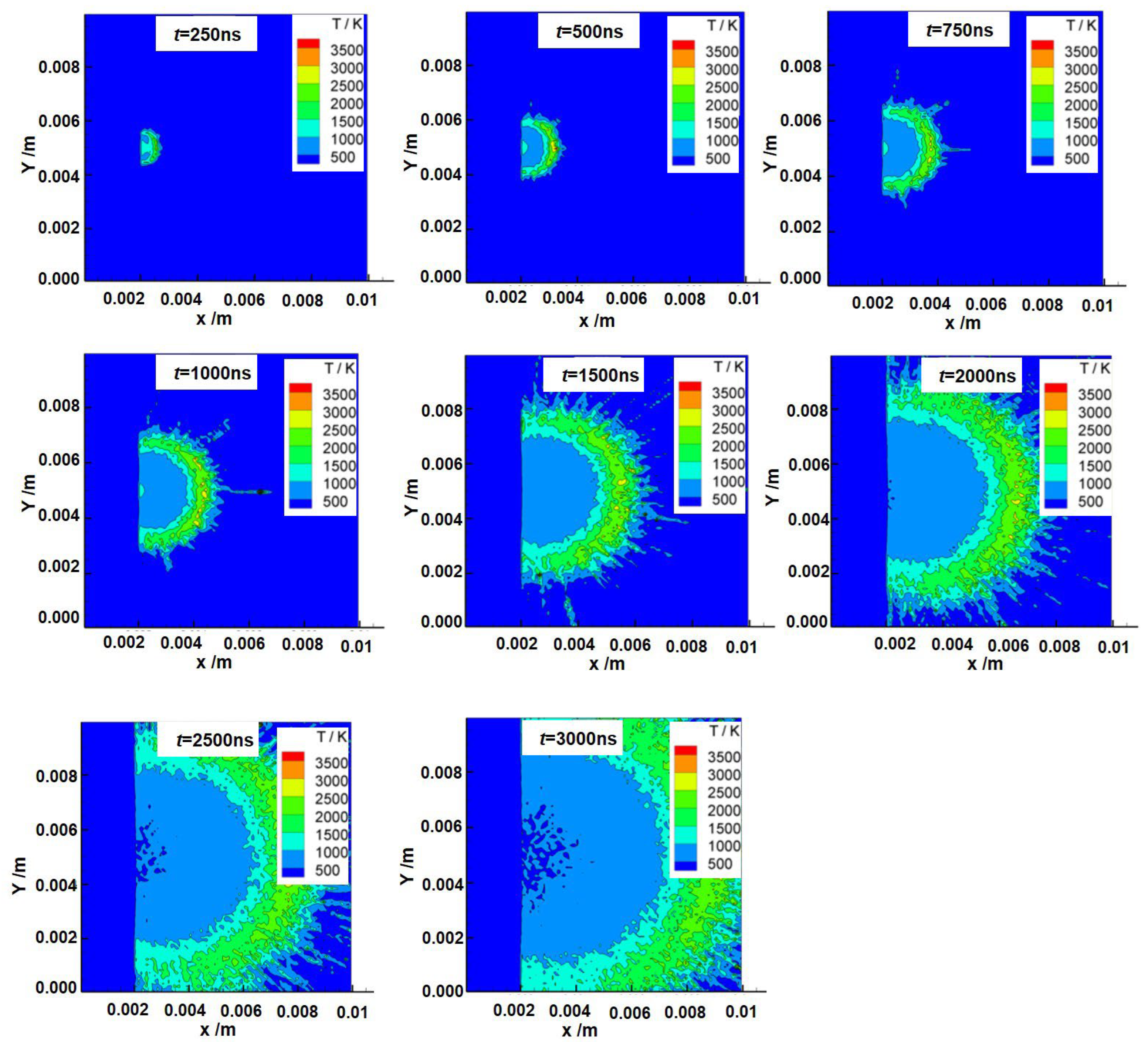
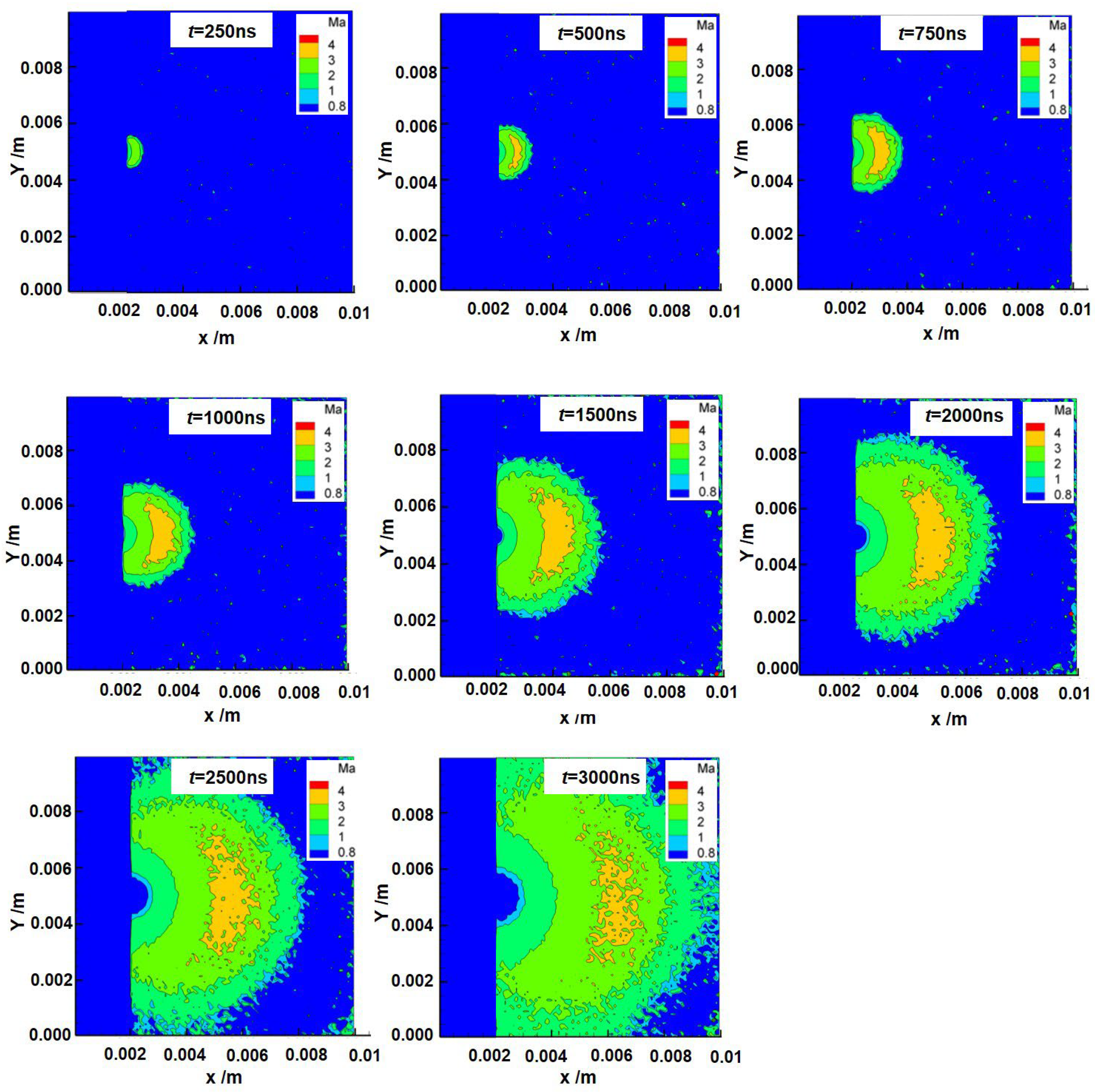
3.1. Test Results

In the simulation of multiphase flow, the core idea of the density calculation is to couple the physical property parameters of each phase through the phase fraction. We use the VOF (Volume of Fluid) method, with gas–liquid dual phases as an example, and the calculation steps are as follows: (1) Create a phase fraction field in a file: the initial value defines the liquid phase area as 1 and that of the gas phase as 0. (2) Solve the phase transport equation: the phase fraction equation with the interface is solved using the MULES algorithm. (3) Calculate the mixed density: the weighted average based on the phase fraction is calculated in the created field. (4) Transfer the physical properties: the dynamic viscosity and other physical parameters are updated synchronously. (5) Debug the density distribution: if the density distribution is abnormal, it is debugged by checking the phase fraction range, the sharpness of the interface, and the stability of the time step.
Using simulation analysis, the calculated density values during the operation of the laser thruster were obtained. The simulation results in Figure 5 show that the density of the ejected particles is highest at the moment they detach from the target material, reaching 4 × 10⁻⁶ Kg/m3. As the ejected particles gradually expand towards the cosmic environment, they undergo diffusion; thus, the density of the ejected particles gradually decreases. Moreover, the position with the highest density in the ejected particle cloud map gradually moves forward over time. From the particle diffusion profile, it is easy to see that the moving speed at the position with the highest density is lower than the propulsion speed at the front edge of the ejected particles. After laser ablation of the target, the density cloud profile spreads outward in the shape of a hemispherical wave in the range of 0–3000 ns.
Using simulations, the calculated pressure values during the operation of the laser thruster were obtained. As shown in Figure 6, the pressure of the ejected particles is highest at the moment they detach from the target material, reaching 0.9 Pa. As the ejected particles gradually expand towards the cosmic environment, they undergo diffusion; thus, the pressure of the ejected particles gradually decreases. Moreover, the position with the highest pressure in the ejected particle cloud map gradually moves forward over time. It is worth noting that the maximum pressure value is at the center of the diffusion spherical wave.
Using this simulation method, the calculated temperature values during the operation of the laser thruster were obtained. The simulation results in Figure 7 show that the higher the energy and velocity of the ejected particles, the higher the temperature. Therefore, the front of the temperature field cloud map is somewhat similar to the front of the velocity field. The temperature is highest at the moment of ejection, reaching 3000 K. As the ejected particles expand towards the cosmic environment, the faster ejected particles move forward, so the high-speed particles always appear at the front of the ejection waveform. The ejected particles will collide with other ejected particles or particles in the universe during the expansion process, resulting in a loss of ability and a decrease in velocity. Therefore, the number of ejected particles with velocities greater than 2000 m/s will gradually decrease over time.
Figure 8 shows the simulation results for the Mach number of the generated plume of the laser ablation of the GAP target, which reaches a value of four. Alongside the expansion of the jet particles into the cosmic environment, particles with higher velocities are also moving forward; therefore, the high-speed jet particles consistently appear at the front of the jet waveform. During the expansion of the jet particles, collisions with other jet particles or particles in the universe occur, resulting in a decrease in movement speed. Therefore, the number of jet particles with a speed greater than 2000 m/s decreases with time. As with the parameters of temperature, the location of the maximum Mach number is not at the center of the spherical wave but near the inner edge of the sphere.
In order to compare changes in the evolving density, pressure, temperature, and velocity of the laser ablation plumes over time, the outer edge and center positions of the laser ablation plume were recorded (Figure 9a,b). From the figure, it can be observed that the evolution speeds of the different plume flow-field parameters, from fast to slow, are in the following order: temperature, pressure, and density. The three parameters show a linear relationship with the evolution time of the flow field (250–3000 ns). The center position of the plume temperature in Figure 9b is significantly faster than the density and pressure, mainly due to the absorption mechanism of the millisecond laser ablation target material and the incompletely ionized plume products [10,27]. In addition, it can be seen from the simulation results that after the laser ablation of the target material, the center point positions of various physical parameters gradually diffuse outward over time, rather than spreading outward in a standard hemispherical shape.
As shown in Figure 10, the state parameters of the plume 1000 ns after laser ablation of the GAP target are used to compare the effects of different vacuum back-pressure conditions. According to the working conditions of the laser thruster, the vacuum back-pressure environment corresponds to different orbital altitudes, i.e., near-Earth, synchronous, and interplanetary orbits. The corresponding vacuum degrees are 10−3 Pa, 10−6 Pa, and 10−9 Pa, respectively. The minimum boundary of the laser ignition process is 10−3 Pa in the present simulation. The simulation results for different vacuum back-pressure conditions indicate that the density, temperature, pressure, and Mach number parameters remain the same in 10−3 Pa, 10−6 Pa, and 10−9 Pa conditions. The different vacuum back-pressure conditions are associated with similar density, temperature, pressure, and Mach number values, and there is no significant change overall. Therefore, the simulation results verify that the laser thruster plume flow-field evolution is similar at different orbital altitudes, i.e., different back-pressure environments.

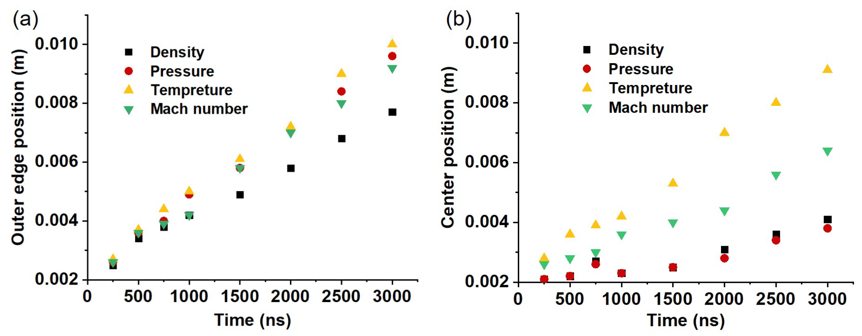
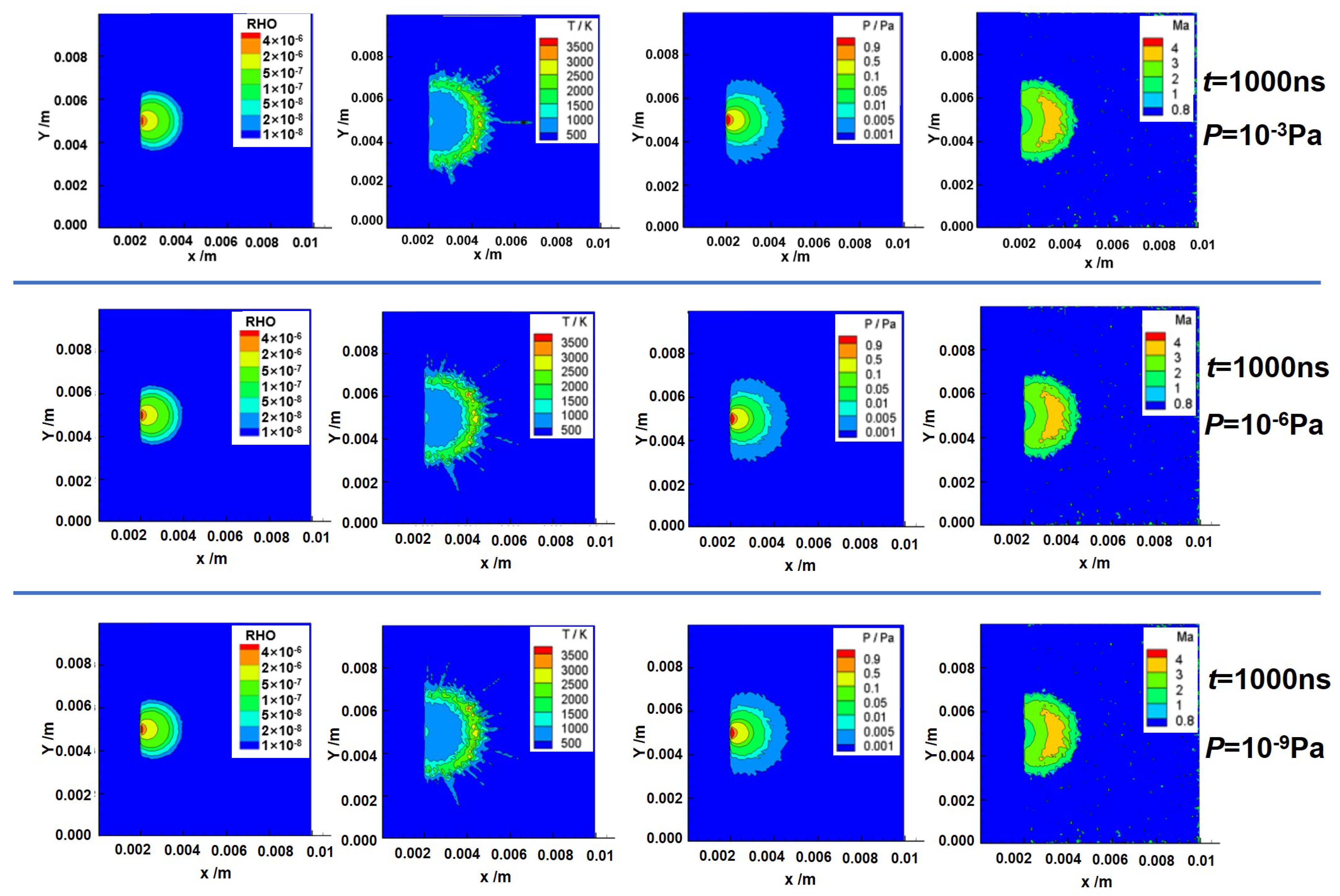
3.2. Test Verification and Analysis

In order to verify the correctness of the simulation test results for the laser thruster, the simulation results at each time segment are compared with the measurement results for the ignition test image of the plume field captured using a high-speed camera. Details on the experimental materials and equipment are shown in Appendix A.
The plume flow-field testing system is shown in Figure 11, and the entire Schlieren system is tested under vacuum conditions in a vacuum chamber. The energy of the semiconductor laser in the figure is 40 mJ, the pulse width is 100 µs, and the ablation uses a pulsed laser. The target material is GAP on a transparent PET substrate. Flash sources are used to supplement light intensity. High-speed cameras are used to capture flow-field evolution images, with a minimum exposure time of 3 ns. The signal transmitter (DG645) is connected to the high-speed laser camera and flash source to adjust the working timing of all three. After the laser emits light, the DG645 sends signals to the high-speed cameras and flash sources to capture and photograph the evolution of the plume. The evolution process of the plume flow field for a single pulse is analyzed. The illustrations in Figure 12a–d show Schlieren images under different exposure time conditions. From the results, it can be seen that significant shock waves are generated at 250 ns, 500 ns, 750 ns, 1000 ns, 1500 ns, 2000 ns, 2500 ns, and 3000 ns. Concordance with the simulation results pertaining to the outer edge of the shock wave is relatively high. From the experimental results, it can be seen that the GAP target material is not completely ionized under the action of the laser. The laser-ablated plume material is ejected from the target surface, and the shape of the plume ejected is semi-circular. The shock wave formed by the laser is rapidly ejected outward along the direction of the jet.
From the shaded part of the high-speed camera image, it can be seen that the edge of the shadow of the plume development should be at the front of the plume shock wave. Therefore, the edge of the shadow in the image was compared with the density simulation results. A discussion of the comparison between the test images and simulation results for the laser-transmitted plume region is given below. The comparison time points selected for this research were 250 ns, 500 ns, 750 ns, 1000 ns, 1500 ns, 2000 ns, 2500 ns, and 3000 ns.
The simulation results show a certain correlation between the shock front and density front at 250 ns, 500 ns, 750 ns, 1000 ns, 1500 ns, 2000 ns, and 2500 ns, and the consistency is high. The shock front disappears in the image captured by the high-speed camera at 3000 ns. Although the shock front cannot be compared at this time, the central position of the density in the image at 3000 ns is consistent with that in the simulation results. From the above simulation and experimental results, it can be concluded that a foundation for the prediction model of a laser thruster under vacuum environments was successfully established. Our results also provide an important reference for ground tests and in-orbit applications of micro-/nanosatellite laser propulsion systems. Figure 13 shows the comparison between the simulation value at the density front and the experimental value at the shock front, revealing that these two values have good concordance, with a difference of less than 10.4% between the two from 0 to 3000 ns. The 10.4% difference between the experimental and simulated values is mainly due to inconsistencies in the experimental process, for example, in the vacuum environment, the incident angle of the laser, the flatness, and the uniformity of the target material. These factors can all affect the diffusion state of the plume. In addition, the boundary conditions also deviate from the experimental values. An example of this is that the laser parameters and the laser energy deposition efficiency are ideal values in the simulation process, whereas there are deviations in these parameters in the experimental laser–matter interaction process. Thus, it can be observed that the actual plume field generated by the laser micro-ablation of the target material is consistent with the results obtained from theoretical model simulation, which verifies the correctness of the simulation result of this model and provides an effective means for predicting the flow field for laser thruster ignition tests under vacuum environments. It is worth noting that the two-dimensional simulation, equivalent to an infinitely long space perpendicular to the paper in terms of space, cannot completely and truly simulate the effect of back pressure. However, the particles at the boundary still have a certain influence on the internal flow field and can qualitatively reflect a certain back pressure. In the future, we will conduct more in-depth and systematic research to make up for this deficiency.

4. Conclusions

Laser propulsion is a novel technology that is highly valued for its advantages, such as its higher specific impulse, efficiency of propulsion, and payload ratio, compared to traditional chemical propulsion technology, and it has important application potential in the aerospace field. In this study, a simulation physical model of the ignition of a laser thruster in a vacuum back-pressure environment is proposed that is based on the actual structure and working mode of a laser thruster. Changes in the flow-field distribution in the plume range of the laser thruster in different vacuum back-pressure environments are obtained through the finite difference and DSMC methods, and the influence of different vacuum back-pressure environments on the plume velocity and pressure fields of the laser thruster is verified using physical experiments. The simulation results are in good concordance with the experimental results, with a difference of less than 10.4% between the two from 0 to 3000 ns. This work lays the foundation for developing a prediction model for laser thruster ignition tests under vacuum environments and provides an important reference for ground experiments and on-orbit applications of satellite laser propulsion systems.

Author Contributions

Conceptualization, M.W. and B.D.; methodology, M.W.; software, J.H.; validation, B.D.; formal analysis, M.W.; investigation, B.D.; resources, M.W.; data curation, M.W.; writing—original draft preparation, B.D. and M.W.; writing—review and editing, M.W., H.C. and B.D.; visualization, B.D.; supervision, M.W.; project administration, M.W.; funding acquisition, M.W. All authors have read and agreed to the published version of the manuscript.

Funding

This research received no external funding.

Data Availability Statement

The data presented in this study are available upon request from the corresponding author. The data are not publicly available due to privacy restrictions.

Conflicts of Interest

The authors declare no conflicts of interest. The funders had no role in the design of the study; in the collection, analyses, or interpretation of the data; in the writing of the manuscript; or in the decision to publish the results.

Appendix A

Experimental materials and equipment: The GAP target material (4% carbon doping) was provided by the Beijing Institute of Technology. A high-speed camera (TRC411, maximum pixels 1680 × 1088, frame rate 93 fps, pixel size 9 µm, minimum exposure time 3 ns, and spatial resolution > 28 lp/mm) was used for laser focusing and observing the evolution of the flow field. A signal generator (DG645, resolution 5 Ps, accuracy 1 ns, jitter external trigger < 25 ps, internal trigger < 15 ps, and external trigger delay 85 ns) was used for external triggering of the laser and high-speed camera. The light source was provided by Beijing Newbit Technology Co., Ltd. (HSX-F/UV300, Beijing, China). The stripline mirrors and optical convex lenses were purchased from Daheng Optoelectronics’ online shop. The semiconductor laser was custom-made by China Electronics Technology Group Corporation (CETGC), with a center wavelength of 987 nm, a peak power density of about 105 W/cm2, a single pulse energy of 40 mJ, a focal spot size adjustable in the range of 100–1000 μm, a focal length adjustable in the range of 2–10 mm, and a pulse width of 100 µs.

References

  1. Abbas, A.; Iqbal, S.T.; Jamil, Y. Ablative laser propulsion, the propellants and measuring parameters: A brief review. J. Laser Appl. 2024, 36, 021201. [Google Scholar] [CrossRef]
  2. Yu, H.C.; Li, H.Y.; Wang, Y.; Cui, L.G.; Liu, S.Q.; Yang, J. Brief review on pulse laser propulsion. Opt. Laser. Technol. 2018, 100, 57–74. [Google Scholar] [CrossRef]
  3. Chen, J.; Li, G.X.; Zhang, T.; Wang, M.; Yu, Y.S. Experimental investigation of the catalytic decomposition and combustion characteristics of a non-toxic ammonium dinitramide (ADN)-based monopropellant thruster. Acta Astronaut. 2016, 129, 367–373. [Google Scholar] [CrossRef]
  4. Rahman, A.; Chin, J.; Kabir, F.; Hung, Y.M. Characterisation and thrust measurements from electrolytic decomposition of Ammonium Dinitramide (ADN) based liquid monopropellant FLP-103 in MEMS thrusters. Chin. J. Chem. Eng. 2018, 26, 1992–2002. [Google Scholar] [CrossRef]
  5. Sandu, C.; Silivestru, V.; Cican, G.; Șerbescu, H.; Tipa, T.; Totu, A.; Radu, A. On a new type of combined solar–thermal/cold gas propulsion system used for LEO satellite’s attitude control. Appl. Sci. 2020, 10, 7197. [Google Scholar] [CrossRef]
  6. Martínez, J.M.; Lafleur, T. On the selection of propellants for cold/warm gas propulsion systems. Acta Astronaut. 2023, 212, 54–69. [Google Scholar] [CrossRef]
  7. Jiao, L.; Cai, J.; Ma, H.H.; Li, G.X.; Li, L.; Shen, Z.W.; Tang, Z.P. Research on applications of rectangular beam in micro laser propulsion. Appl. Surf. Sci. 2014, 301, 481–487. [Google Scholar] [CrossRef]
  8. Mori, K. Laser-propelled launch of a spherical capsule guided by a donut-mode beam. J. Spacecr. Rocket. 2017, 54, 1180–1183. [Google Scholar] [CrossRef]
  9. Wang, S.B.; Du, B.D.; Du, B.S.; Zheng, Y.Z.; Hong, Y.J.; Ye, J.F.; Xing, B.Y.; Li, C.L.; Zhang, Y.H. Impacts of laser pulse width and target thickness on laser micro-propulsion performance. Plasma Sci. Technol. 2022, 24, 105504. [Google Scholar] [CrossRef]
  10. Du, B.S.; Zheng, Y.Z.; Mao, C.T.; Cui, H.C.; Han, J.H.; Jiang, L.Y.; Ye, J.F.; Hong, Y.J. Transmissive Mode Laser Micro-Ablation Performance of Ammonium Dinitramide-Based Liquid Propellant for Laser Micro-Thruster. Micromachines 2023, 14, 1219. [Google Scholar] [CrossRef]
  11. Lemmer, K. Propulsion for CubeSats. Acta Astronaut. 2017, 134, 231–243. [Google Scholar] [CrossRef]
  12. Xu, R.P.; Tang, Z.P. Numerical simulation for laser propulsion of air breathing mode considering multi-pulses. High Power Laser Part. Beams 2007, 19, 369–372. [Google Scholar]
  13. Blockley, R.; Shyy, W. Laser Propulsion, Encyclopedia of Aerospace Engineering; John Wiley & Sons Ltd.: Chichester, UK, 2010. [Google Scholar] [CrossRef]
  14. Bondar, Y.A.; Schweigert, V.A.; Ivanov, M.S. Modeling of the hall-effect thruster plume by combined PIC-MCC/DSMC method. AIP Conf. Proc. 2003, 663, 549–556. [Google Scholar]
  15. Nishii, K.; Levin, D.A. Three dimensional kinetic simulations of carbon back sputtering in vacuum chambers from ion thruster plumes. J. Propul. Power 2024, 40, 123–137. [Google Scholar] [CrossRef]
  16. Fang, H.K.; Oyama, K.I.; Cheng, C.Z. Plasma measurements in the space plasma operation chamber (SPOC). Chin. J. Phys. 2015, 53, 123–137. [Google Scholar]
  17. Aslanov, V.S.; Ledkov, A.S. The ion beam interceptor concept for a space station collision avoidance with space debris. Acta Astronaut. 2024, 223, 49–57. [Google Scholar] [CrossRef]
  18. Tan, R.; Hang, G.R.; Wang, P.Y. Optimization of magnetic field design for Hall thrusters based on a genetic algorithm. Plasma Sci. Technol. 2024, 26, 075503. [Google Scholar] [CrossRef]
  19. Yamashita, Y.; Tsukizaki, R.; Nishiyama, K. Effect of ion beam extraction on neutral density distribution inside a gridded microwave discharge ion thruster. Vacuum 2022, 200, 100962. [Google Scholar] [CrossRef]
  20. He, B.J.; Zhang, J.H.; Cai, G.B. Research on vacuum plume and its effects. Chin. J. Aeronaut. 2013, 26, 27–36. [Google Scholar] [CrossRef]
  21. Tani, H.; Ohmaru, T. Hybrid continuum/rarefied flow simulations of plume interaction with full-sized spacecraft. J. Spacecr. Rocket. 2022, 59, 660–673. [Google Scholar] [CrossRef]
  22. Copplestone, S.; Ortwein, P.; Munz, C.D.; Binder, T.; Mirza, A.; Nizenkov, P.; Pfeiffer, M.; Fasoulas, S. Coupled PIC-DSMC Simulations of a Laser-Driven Plasma Expansion. In High Performance Computing in Science and Engineering ’15; Nagel, W., Kröner, D., Resch, M., Eds.; Springer: Cham, Switzerland, 2015. [Google Scholar] [CrossRef]
  23. Richard, J.T.; Trevor, M.M. Computational investigations of performance improvements for microlaser ablation plasma thrusters using nozzles. IEEE Trans. Plasma Sci. 2011, 39, 2932–2933. [Google Scholar]
  24. Boyd, I.D.; Keidar, M. Simulation of the plume generated by a micro laser-ablation plasma thruster. In Proceedings of the High-Power Laser Ablation IV, Taos, NM, USA, 13 September 2002. [Google Scholar]
  25. Tang, Z.P.; Xu, R.P. Numerical study on thermal mechanical impact failure mechanism for annular focusing laser thrusters. AIP Conf. Proc. 2010, 111, 1230. [Google Scholar]
  26. Chen, H.; Shi, L.; Ma, L.H.; Chen, Y.G. Numerical simulation of air-breathing nanosecond laser propulsion considering subsonic inflow and multi-pulse. Optik 2014, 125, 3444–3448. [Google Scholar] [CrossRef]
  27. Mao, C.T.; Jing, L.Y.; Du, B.S.; Zheng, Y.Z.; Cui, H.C.; Wang, D.K.; Ye, J.F.; Han, J.H.; Hong, Y.J. Theoretical investigation of laser ablation propulsion using micro-scale fluid in atmosphere. Aerospace 2024, 11, 622. [Google Scholar] [CrossRef]
Figure 1. Analytical model of laser thruster ignition (a) and a physical model of the ignition process (b).
Aerospace 12 00445 g001
Figure 2. Establishment of a simulation analysis model for a laser thruster.
Aerospace 12 00445 g002
Figure 3. Grid division of the model (a) and region division by boundary condition (b).
Aerospace 12 00445 g003
Figure 4. DSMC analysis model.
Aerospace 12 00445 g004
Figure 5. Density cloud during the operation of the laser thruster (RHO is density; units are in kg/m3).
Aerospace 12 00445 g005
Figure 6. Pressure cloud during the operation of the laser thruster.
Aerospace 12 00445 g006
Figure 7. Temperature cloud during operation of laser thruster.
Aerospace 12 00445 g007
Figure 8. Mach number during operation of laser thruster.
Aerospace 12 00445 g008
Figure 9. (a) Variations in the outer edge positions of plume density, pressure, and temperature as the plume flow field evolves over time. (b) Variation in the center position of plume density, pressure, and temperature as the plume flow field evolves over time.
Aerospace 12 00445 g009
Figure 10. The physical parameters of the plume 1000 ns after laser ablation of the GAP target with different vacuum back-pressure conditions.
Aerospace 12 00445 g010
Figure 11. The plume flow-field evolution testing system.
Aerospace 12 00445 g011
Figure 12. Schlieren images of laser ablation of the GAP target at different exposure times (250 ns (a); 500 ns (b); 750 ns (c); 1000 ns (d); 1500 ns (e); 2000 ns (f); 2500 ns (g); and 3000 ns (h)).
Aerospace 12 00445 g012
Figure 13. Comparison between experimental and simulation values at the density front.
Aerospace 12 00445 g013
Table 1. Physical laser ablation parameters.
Boundary Condition ParametersValue
Target materialC-doped GAP
Thickness of target material100 µm
Quality loss10 µg/s
Laser power density105 W/cm2
Laser spot0.3 mm × 0.3 mm
Laser pulse width1 ms
Laser energy40 mJ
Laser energy deposition efficiency~80%
Pressure at the outlet10−3 Pa; 10−6 Pa; 10−9 Pa
Disclaimer/Publisher’s Note: The statements, opinions and data contained in all publications are solely those of the individual author(s) and contributor(s) and not of MDPI and/or the editor(s). MDPI and/or the editor(s) disclaim responsibility for any injury to people or property resulting from any ideas, methods, instructions or products referred to in the content.

