Article

Structural and Topological Optimization of a Novel Elephant Trunk Mechanism for Morphing Wing Applications

by
Mir Hossein Negahban
,
Alexandre Hallonet
,
Marie Noupoussi Woumeni
,
Constance Nguyen
and
Ruxandra Mihaela Botez
*
LARCASE Laboratory of Applied Research in Active Controls, Avionics and Aeroservoelasticity, École deTechnologie Supérieure, Université du Québec, Montreal, QC H3C 1K3, Canada
*
Author to whom correspondence should be addressed.
Aerospace 2025, 12(5), 381; https://doi.org/10.3390/aerospace12050381
Submission received: 24 March 2025 / Revised: 24 April 2025 / Accepted: 26 April 2025 / Published: 28 April 2025
(This article belongs to the Special Issue Aircraft Design and System Optimization)

Abstract

:
A novel mechanism for seamless morphing trailing edge flaps is presented in this paper. This bio-inspired morphing concept is derived from an elephant’s trunk and is called the Elephant Trunk Mechanism (ETM). The structural flexibility of an elephant’s trunk and its ability to perform various types of deformations make it a promising choice in morphing technology for increasing the performance of continuous and smooth downward bending deformation at a trailing edge. This mechanism consists of a number of tooth-like elements attached to a solid wing box; the contractions of these tooth-like elements by external actuation forces change the trailing edge shape in the downwards direction. The main actuation forces are applied through wire ropes passing through tooth-like elements to generate the desired contractions on the flexible teeth. A static structural analysis using the Finite Element Method (FEM) is performed to examine this novel morphing concept and ensure its structural feasibility and stability. Topology optimization is also performed to find the optimum configuration with the objective of reducing the structural weight. The optimized mechanism is then attached to the flap section of a UAS-S45 wing. Finally, a skin analysis is performed to find its optimum skin material, which corresponds to the requirements of the morphing flap. The results of structural analysis and topology optimization reveal the reliability and stability of the proposed mechanism for application in the Seamless Morphing Trailing Edge (SMTE) flap. The optimization results led to significant improvements in the structural parameters, in addition to the desired weight reduction. The ETM maximum vertical displacement increased by 8.6%, while the von Mises stress decreased by 10.43%. Furthermore, the factor of safety improved from 1.3 to 1.5, thus indicating a safer design. The mass of the structure was reduced by 35.5%, achieving the primary goal of topology optimization.

1. Introduction

Aerodynamic studies have shown that morphing wing technology [1] was widely believed to be one of the ways to meet the goals of green aviation [2] by improving aircraft aerodynamic performance, in particular fuel consumption reduction, which directly leads to lower carbon emissions. Morphing wing technology is a promising candidate for next-generation aircraft due to its numerous advantages. While the current hinged flaps used in the existing fleet have demonstrated reliable performance over the past decades, they have introduced discontinuities on the wing surface that lead to several flight performance issues. These include increased turbulence, reduced functionality in hazardous climates [3], and increased drag due to the discontinuities on the wing body.
This innovative technology eliminates all discontinuities from the wing surface by integrating the main wing body with the flap sections, resulting in significant improvements in aerodynamic efficiency, fuel consumption reduction, and overall flight performance.
This paper presents unique design challenges, particularly in developing the internal actuation mechanisms for morphing wings, which have been a focal point of research in recent decades. Over the last decade, several collaborative projects aimed at testing different morphing approaches have been launched. The DARPA/AFRL/NASA Smart Wing program, overseen by Northrop Grumman Corporation (NGC) as part of the DARPA Smart Materials and Structures initiative [4], Flexsys and the US Air Force Research Laboratory [5], the CRIAQ MDO-505, a Canadian-Italian collaborative project [6], and Clean Sky 2 [7] in Europe are some of these projects that have brought morphing technology up to the test level. This level of study requires researchers to work in multiple disciplines, including aerodynamics, structure, and control.
Structural analysis concerns both the internal actuation mechanism and the external wing skin design, both of which are complimentary in the structural design. This phase of the design must comply with the aerodynamic design; any compromise in this phase could deteriorate the final wing design. Therefore, structural design, whether actuation design or skin design, should be treated meticulously. While a high number of morphing actuation designs have been proposed and then developed, however, most of these conceptual designs lack the desired feasibility at a practical level. Among various morphing designs, such as winglet [8,9], span [10], twist [11], upper surface morphing [12], or leading-edge morphing [13,14], trailing-edge morphing has demonstrated outstanding results over the past decades. Consequently, most research in mechanism design has concentrated on developing morphing trailing-edge mechanisms, while it needs to be tested in a wind tunnel due to its promising advantages in aircraft performance improvement.
The Fishbone Active Camber (FishBAC) was an airfoil morphing structure presented by Woods et al. [15] in 2012. Utilizing a compliant structure derived from biological inspiration, the FishBAC introduced significant improvements in the aerodynamic qualities of an airfoil camber. The framework consisted of a thin, chordwise-bending beam spine connected to a pre-tensioned Elastomeric Matrix Composite (EMC) skin surface using stringers. Thus, several possible morphing configurations were presented. In their later study [16], Woods et al. compared the FishBAC structure to a conventional flap during wind tunnel tests, and they found that using the FishBAC, a significant drag reduction was obtained in the proposed morphing wing compared to the baseline configuration, while the lift remained the same. The Variable Camber Trailing Edge (VCTE), developed by Shi et al. [17], was another design for a morphing trailing edge. Based on a multi-block rotating rib, it consisted of three morphing blocks and one fixed block, hinged together; the actuation of any block was followed by the movements of other blocks. Their results showed a continuous and smooth deformation, ranging from 5° upwards to 15° downwards without damaging structural integrity. Cheng et al. [18] proposed and developed a seamless morphing trailing edge with chord-wise camber variations and a good capacity for load bearing. Finite element numerical simulations and experimental tests demonstrated that their proposed mechanism sustained the aerodynamic loads of 0.015 MPa and achieved deflections of 15° both upwards and downwards.
Within the European SARISTU project, an innovative actuation system for morphing trailing edges was developed by Dimino et al. [19]. They have modeled and analyzed a morphing actuation system composed of servo rotary actuators with the design objectives of supporting aerodynamic pressure loads and actuation forces. Their internal mechanism with a flexible outer skin was subjected to numerical, analytical, and experimental validations. In addition to its higher accuracy, the mechanism could significantly save weight and actuation power and withstand aerodynamic forces. A belt-rib morphing variable camber concept was developed at the German Aerospace Center (DLR) by Campanile and Sachau [20]. This concept has been considered as one of the most successful designs for morphing wings, mainly due to its reliable structure and light weight. Its distributed flexibility allowed for a range of shape deformations. Through experimental tests on different prototypes, its stiffness properties were evaluated and then followed by weight optimization. Another morphing trailing edge concept was also introduced at the DLR [21], called the “finger concept”. In this concept, a flexible rib design combined from separate plate-like elements with revolute joints could generate arc-like deformation. A transmission beam was used to arrange the ribs, and five ribs were actuated with two actuators, leading to a reduced number of actuators. A smart-actuated trailing edge via smart materials was investigated by Wang et al. [22]. Their mechanism could perform upward and downward deflections by using SMA wires. A control system was developed to assess the mechanism’s accuracy; it indicated that this approach yielded accurate and stable results, with its maximum error less than 4%. However, the actuation response time reached 6.7 s. Wu et al. [23] introduced another innovative morphing concept featuring an active trailing edge, utilizing an internal compliant composite truss. They used an electric actuation system with Linear Ultrasonic Motors (LUSMs) with the capability of performing multiple degrees of freedom. Dumont [24] introduced an alternative trailing edge morphing concept, proposing a system with two flexible surfaces positioned at the upper and lower sides of the wing, each of them equipped with three internal rotational motors. The rotational motion of motors was transferred to the bending of the flexible surfaces in a very smooth manner. A specified degree of rotation was translated as a certain degree of bending both in the upwards and downwards directions by preserving surface tangency and smoothness. Bing Li and Gang Li [25] proposed a camber morphing wing model that could perform continuous camber morphing. Their proposed mechanism consisted of a planar linkage, in which the connection of the linkages was found through optimization. An aerodynamic study was performed to measure the airfoil’s performance after its optimization; finally, a higher lift-to-drag ratio was achieved after optimization. In an experimental study, Nguyen et al. [26] investigated the performance of Variable Camber Continuous Trailing Edge Flaps (VCCTEFs). Their design consisted of multi-segment flaps. To cover the gaps between spanwise flaps, they have used an elastomeric material. The elastic flap had three hinged sections; a combination of SMA and electric actuators was utilized to bend the overall flap using the rotation of interior rods. A structural analysis of the morphing trailing edge flap was conducted by Matteo et al. [27] for a large aircraft wing. The actuation system selected to deflect the trailing edge (TE) flap structure was an Eccentric Beam Actuation Mechanism (EBAM), originally developed in the 1970s as part of the DARPA project. They performed a stress analysis to analyze the flap’s structural motion during actuation and to evaluate its integrity during its trailing edge deflection. Their findings revealed that, under internal actuation and external aerodynamic loads, both composite and metallic skin configurations successfully achieved the desired deflected shapes while meeting their strength constraints.
An Adaptive Trailing Edge Device (ATED) with rotatory segmented ribs was designed by Pecora et al. [28]. The structural analysis based on advanced FE analyses was performed, revealing that the proposed mechanism was reliable in terms of stress and maximum load conditions, as well as elastic stability. A novel concept of variable camber morphing leading and trailing edge sections was introduced by Takahashi et al. [29]. A prototype was manufactured, and both finite element structural analysis and an aerodynamic analysis were performed. The deformation of the leading and trailing edges was achieved by the corrugated structure embedded within the lower and upper surfaces of the wing; the deformation was induced on the corrugated structure by a wire connected to a servomotor. Finally, wind tunnel tests on the manufactured morphing wing prototype were performed, and a successful actuation at the speed of 20 m/s airflow was achieved. Barbarino et al. [30] proposed an innovative flap architecture for variable camber trailing edges based on the variable geometry truss concept. The compliant rib was based on a truss-like structure, on which some of its parts were “active” rods made of Shape Memory Alloys (SMAs). These actuators were able to sustain the external loads while allowing controlled shape modification. An optimization process based on a genetic algorithm was established to optimize the topology of the internal truss structure. In a joint project called the Adaptive Compliant Trailing Edge (ACTE), conducted by the U.S. Air Force Research Laboratory (AFRL), NASA, and FlexSys Inc. [5,31], a series of flight tests were conducted on a Gulfstream GIII business jet with variable geometry multifunctional control surfaces, with the purpose of eliminating the trailing edge flaps. The test flight was conducted up to Mach = 0.75 and a maximum altitude of 40,000 ft. In this design, the control surface was bounded with left and right transition sections, which eliminated all discontinuities on the wing body. The main purpose of the flight tests was to demonstrate the robustness and feasibility of the FlexFoil material; they confirmed that the ACTE was structurally feasible and could perfectly sustain the maximum design loads of commercial aircraft for over 50 h of flight tests without any failure.
A morphing airfoil concept applicable to high-lift devices such as flaps, ailerons [32,33], elevators, and rudders was proposed by Du and Ang [34]. They have compared airfoils with a hinged flap with morphing airfoils with the aim to determine the influence of a morphing airfoil on the aerodynamic efficiency and the flight dynamics of an airplane. In an attempt to passively eliminate discontinuities on the wing trailing edge flap, Khorami et al. [35] from NASA Langley Research Center patented the elastic deformable structure for the side edges of the trailing edge flap. This elastic structure was designed to minimize the aeroacoustic noise caused by discontinuities in the side edge gaps while maintaining the aircraft’s cruise efficiency. This novel configuration could elongate in the chord-wise direction, bend, and twist, and when it was not deployed, it seamlessly conformed to the chord-wise cross-section of the flap’s side edge. Woods et al. [36] presented a compliant morphing flap transition to address the side-edge gaps in the spanwise direction. Their proposed concept design ensured that the gaps were sealed and that the transition between the rigid wing and the morphing flap was smooth.
In the present study, a novel bio-inspired morphing trailing edge mechanism is introduced, called the “Elephant Trunk Mechanism (ETM). As indicated by its name, it is inspired by an elephant’s trunk, which has very good bending flexibility. This type of deformation is analyzed with the objective of applying it to the trailing edge mechanism of the Seamless Morphing Trailing Edge (SMTE) flap, on which an aerodynamic optimization study was performed in a previous work [37]. Fewer movable parts contribute to the ETM’s unique design, making it simpler and lighter compared to other designs presented in the literature. Based on the results obtained in previous work, expressed in terms of geometric constraints and deformation range, in this study, the proposed mechanism is submitted to a complex structural analysis based on the Finite Element Method (FEM) with the aim of ensuring its robustness and functionality. To the authors’ knowledge, the designs introduced in the literature may lack an optimization phase for further weight reduction. However, this study demonstrates that performing topology optimization in the final phase not only reduces unnecessary structural weight, but it also enhances the design from a structural perspective, particularly by increasing the factor of safety. Finally, once the ETM optimum configuration was found, the mechanism was installed on a UAS-S45 wing, and a skin analysis was conducted on the wing to identify a suitable skin material in terms of flexibility and stiffness. The UAS-S45 is a twin-engine tactical unmanned aircraft system with a range of 120 km, an operating ceiling of 17,000 feet, and 12 h of autonomy; it is mainly used for surveillance and reconnaissance [38] (see Appendix A for additional detail). Several studies have been conducted on the UAS-S45 at LARCASE in morphing wing technology [39,40,41,42]; most of these studies were performed around aerodynamic optimization. However, in this study, the main purpose is to structurally evaluate the viability of the mechanism and its advantages.

2. Materials and Methods

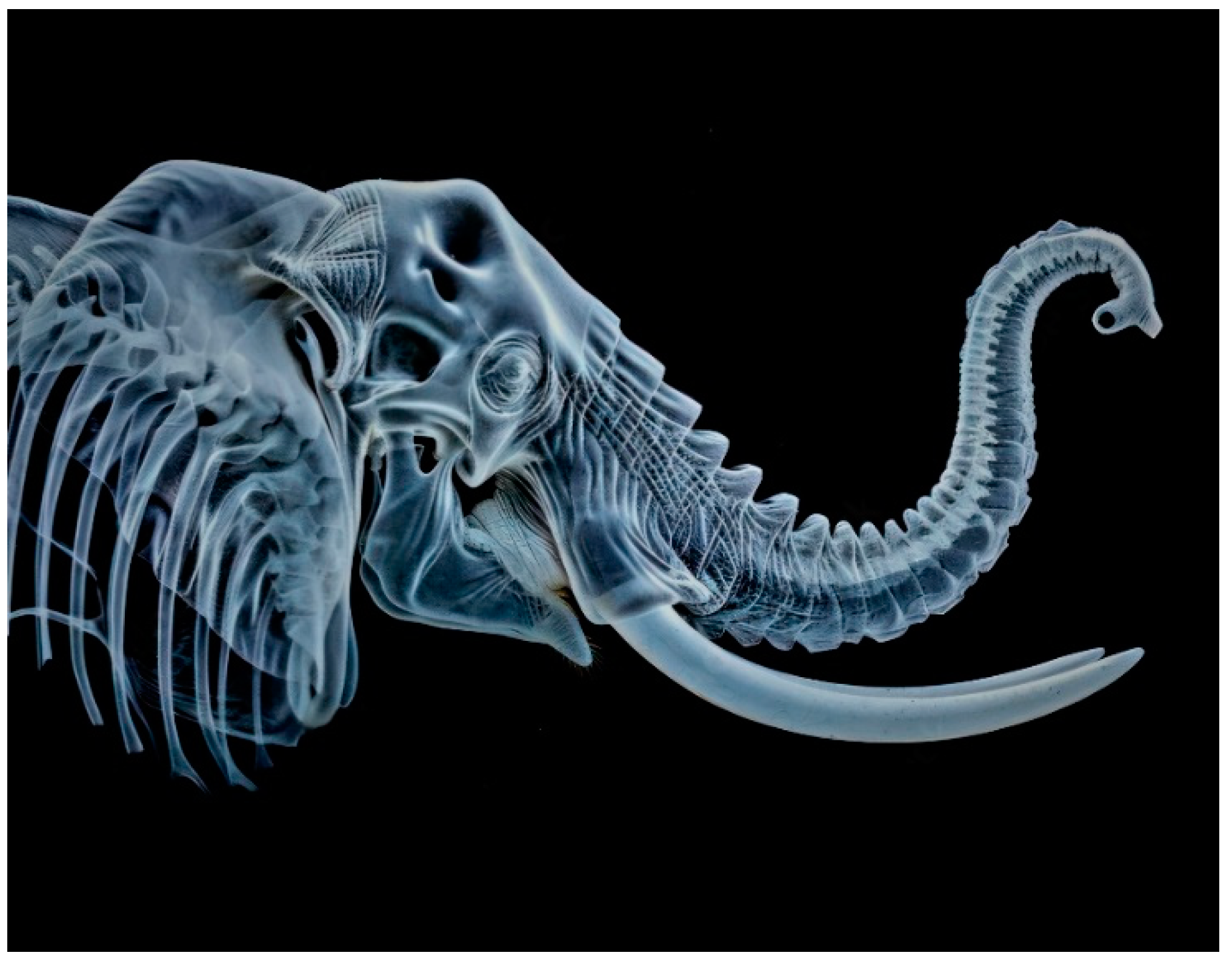
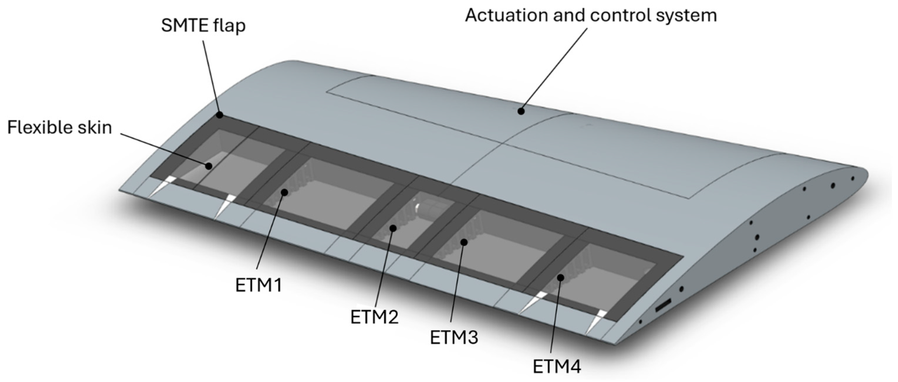
2.1. Elephant Trunk Mechanism (ETM)

The motion of biological muscle hydrostats, such as octopus arms, squid tentacles, and elephant trunks, is remarkably versatile [43]. Their lack of a skeletal structure and a combination of muscle and soft tissue make them extremely complex. The biomechanics of their motions are based on the fundamental principle of volume conservation. For instance, a squid tentacle elongates when contraction occurs in transversely oriented muscle fibers [44]. Several industrial applications of the elephant trunk mechanism were analyzed, one of which is the elephant trunk robot used as a gripping mechanism (Yang et al. [45]), where its flexible rotational and bending motions were applied using a computer-controlled actuation system.
As an application in the aerospace industry, the bio-inspired Elephant Trunk Mechanism (ETM) is introduced in this paper for an application in morphing wing technology, utilizing the bending flexibility of the trunk in the morphing of a trailing edge, a complementary actuation mechanism for a Seamless Morphing Trailing Edge (SMTE) flap [37]. Figure 1 shows a CT scan of an elephant trunk mechanism in detail, clearly depicting its high degrees of freedom. Although contractions of the tooth-like muscles on the trunk facilitate its bending in every direction, in a trailing edge, it is important to mention that teeth contractions are limited to one side (the lower side of the trailing edge) to generate downward deformations. The initial inspired actuation mechanism is illustrated in Figure 2 with its geometric details.
As shown in Figure 2, the proposed Elephant Trunk mechanism for a morphing trailing edge mimics the tooth-like structure of the actual elephant trunk, whose contraction generates the desired deformation in the trailing edge. Three major parts are differentiated in the structure in terms of material and elasticity: 1-cables, 2-elastic tooth-like part, 3-the solid edge part. The main part, where the deformation occurs, is the elastic tooth-like structure, whose contraction generates the desired deformation. It is screwed to the wing box from one side and to the solid edge part from the other side. Unlike an actual elephant’s trunk, where the deformation occurs due to the contraction and expansion of muscles, in the proposed structure, the contraction of the teeth is obtained through tensile forces exerted on the cables. This preliminary system utilizes 3mm diameter cables that pass through the structure’s teeth. Upon the exertion of the force to the cables in the negative x-direction (Figure 2), the tooth-like elements contract towards the direction of the applied force, causing the bending of the structure, and hence of the trailing edge of the wing. Using three cables in this mechanism facilitates the mechanical loads by distributing the total force equally among the three cables.

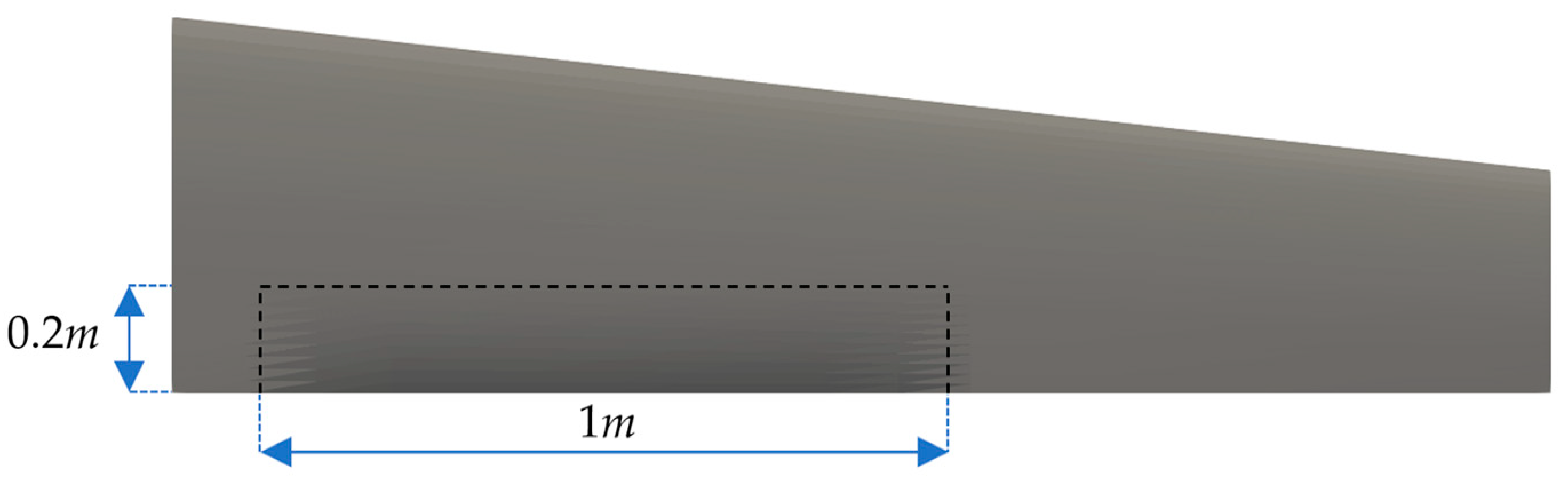
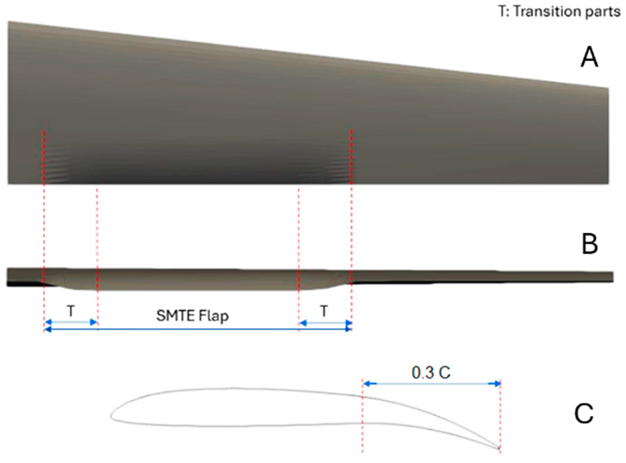
2.2. Aerodynamic Characteristics of the SMTE Flap

The aerodynamic aspects of the SMTE flap were analyzed in a previous study [37], where key characteristics such as aerodynamic efficiency, pressure distribution, and vorticity around the SMTE flap were analyzed. The entire flight envelope for the UAS-S45, including climb, cruise, and descent phases, was considered. Using the DAFoam optimization framework [47,48], the optimal aerodynamic configuration of the SMTE flap was found for each flight condition. Additionally, a comparison was made between the SMTE flap and conventional hinged flaps aerodynamic performance.
The aerodynamic study covered the entire flight envelope, including climb, cruise, and gliding descent conditions. The following results were obtained from the aerodynamic study:
In the climb regime, the optimized SMTE flap achieved a 6.13% increase in climb rate and a 3.8% reduction in required engine power compared to the clean wing. In the cruise regime, the aerodynamic efficiency improved by 33% over the clean wing and 17.8% over a hinged flap due to smoother pressure distribution and extended laminar flow. Finally, in the gliding descent regime, the SMTE flap reduced the descent rate by up to 43%, enabling safer emergency glide paths. The comparison of the SMTE flap with a conventional hinged flap clearly demonstrated the aerodynamic advantage of the seamless design, primarily due to the elimination of flap side-edge gaps, which led to smoother pressure gradients, reduced drag, and enhanced lift generation (see [37] for more detail).
The current study focuses on the actuation mechanism of the SMTE flap-based on previous study findings that are utilized to define the aerodynamic and structural characteristics of the SMTE flap. For example, the proposed Elephant Trunk Mechanism (ETM) must adhere to certain requirements derived from the aerodynamic analysis. The first requirement involves geometrical constraints, ensuring that the SMTE flap dimensions in the current study match those used in the aerodynamic study. The second requirement refers to the maximum vertical deflection of the SMTE flap, to be achieved by the ETM. Additionally, achieving the desired vertical deflection must satisfy structural criteria, such as the factor of safety, mechanism stiffness, material selection, and structural weight. The aerodynamic loads acting on the wings’ trailing edge, containing the SMTE flap, were incorporated in the material selection and adjusting the actuation forces acting on the ETMs. Figure 3 illustrates the geometrical dimensions of the SMTE flap that the proposed actuation mechanism must comply with.
Figure 3 depicts the dimensions of the SMTE flap that was used in the aerodynamic study and will also be used in the present study. In Section 3.7, the orientation of the embedded ETMs will be discussed in detail. Regarding the second requirement, the maximum vertical displacement, obtained from the aerodynamic study, was found to be 66 mm in the downward direction. Therefore, the proposed elephant trunk actuation mechanism should reach the maximum flap deflection of 66 mm.

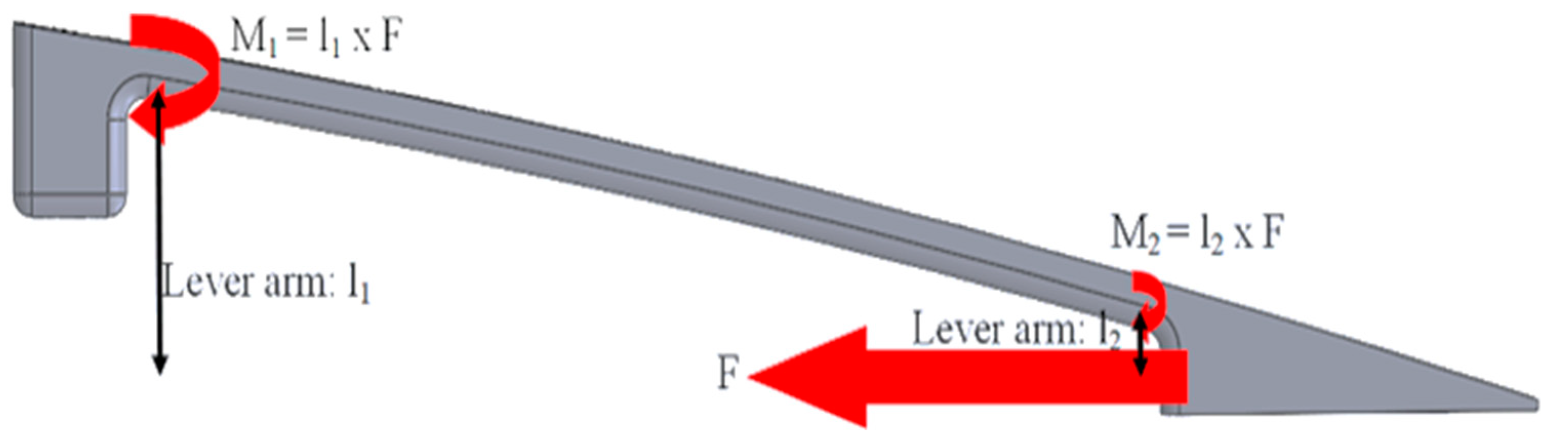
2.3. Structural Analysis

A static structural analysis was performed in Altair using the FEM by considering the constraints and forces applied to the mechanism. Several model equations obtained using the fundamental principles of mechanics were considered during the analysis, including equilibrium, compatibility, and constitutive equations. Equilibrium equations ensure that the resultant of the forces and moments acting on the structure is zero. There are three equilibrium equations for forces and three equations for moments in the 3D Finite Element Analysis (FEM), each of which represents a direction in xyz coordinates. Given that a static analysis is performed, the corresponding equilibrium equation is given by:
K · u = F
where K represents the stiffness of the structure in a square matrix, which is based on the chosen material; u is the vector of nodal displacements; and F denotes the external forces.
The compatibility equations ensure that the displacements of connected nodes are consistent with the deformations and rotations of the elements; therefore, the continuity of displacements is preserved. Finally, the constitutive equations are expressed under the form of Hooke’s law for linear elastic materials and are written as follows.
σ = E · ε
where σ denotes the stress, E is Young’s modulus, and ε is the strain.

2.4. Material Selection

Material selection is the first and most important phase in the FEA. Since the trailing edge is free at one end and is located at least 30% of the chord length, it can bend easily under the gravity force if it is made of a heavy material. However, the aerodynamic forces are stronger on the trailing edge; therefore, it should be stiff enough to not bend by any arbitrary force. By considering these observations, the chosen material should be flexible enough to generate desired bending deformations, stiff enough to bear strong aerodynamic forces, and light enough to not bend under the gravity force. To address these criteria, the aerodynamic loads on the SMTE flap, obtained from a previous study [38], were considered. Based on the aerodynamic forces’ values and the required deflection obtained from the aerodynamic study, nylon was selected as the material for the elastic part of the ETM, while aluminum was selected for the solid edge. It was ensured that the selected material remained undeformed under pure aerodynamic loading, and it achieved the required maximum deflection exclusively under the applied actuation force.
Nylon is a polymer known for its excellent mechanical properties and hence is adaptable for several applications, including those of structural components. In our study, nylon is suitable for elephant trunk structures due to its high tensile strength and flexibility. The tensile strength of a material measures the ultimate stress that the material can resist before breaking when it is undergoing a tension or a compression. The nylon equally allows good flexibility within elastic deformation. This material property is thus suitable for our study, given that the intended mechanism should deform repeatedly in its elastic range during flight. Additionally, nylon has a low friction coefficient, making it especially suitable for this application, as the cables slide within the tooth-like elements. Its light weight equally reduces the overall weight of the mechanism.
For the cables, wire ropes are chosen, as they are strong, flexible, and durable structures made of twisted metal wires within each other. They are commonly used in various applications in which strength, flexibility, and load-bearing capacities are required. The wire ropes used in this study are made from high-carbon steel, which has excellent material properties. Wire ropes are equally known for their high tensile strength in case of heavy loads. Despite their high strength, wire ropes remain flexible, allowing them to comply with various structural shapes. Table 1 shows the material properties of the materials chosen for each part of the mechanism.

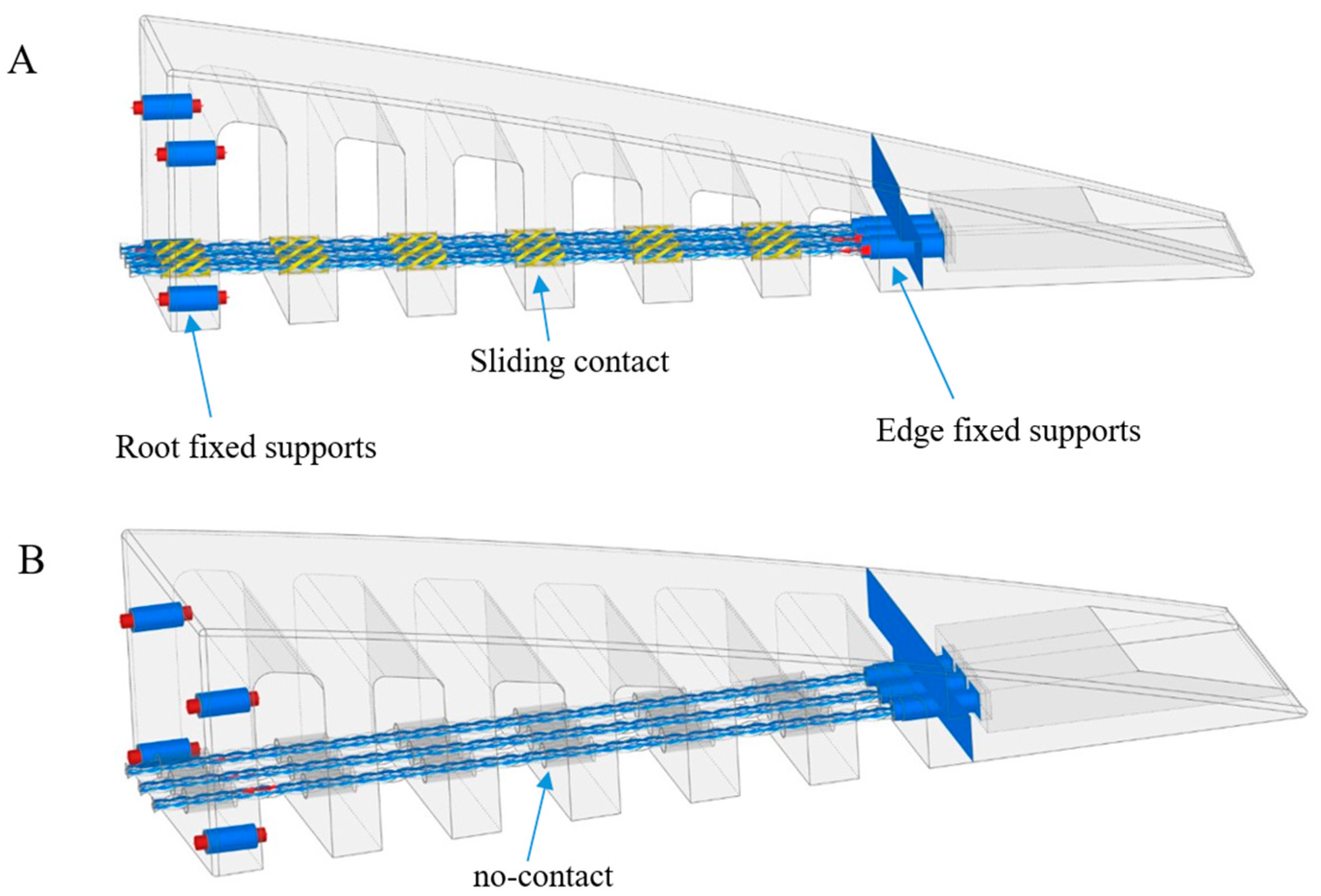
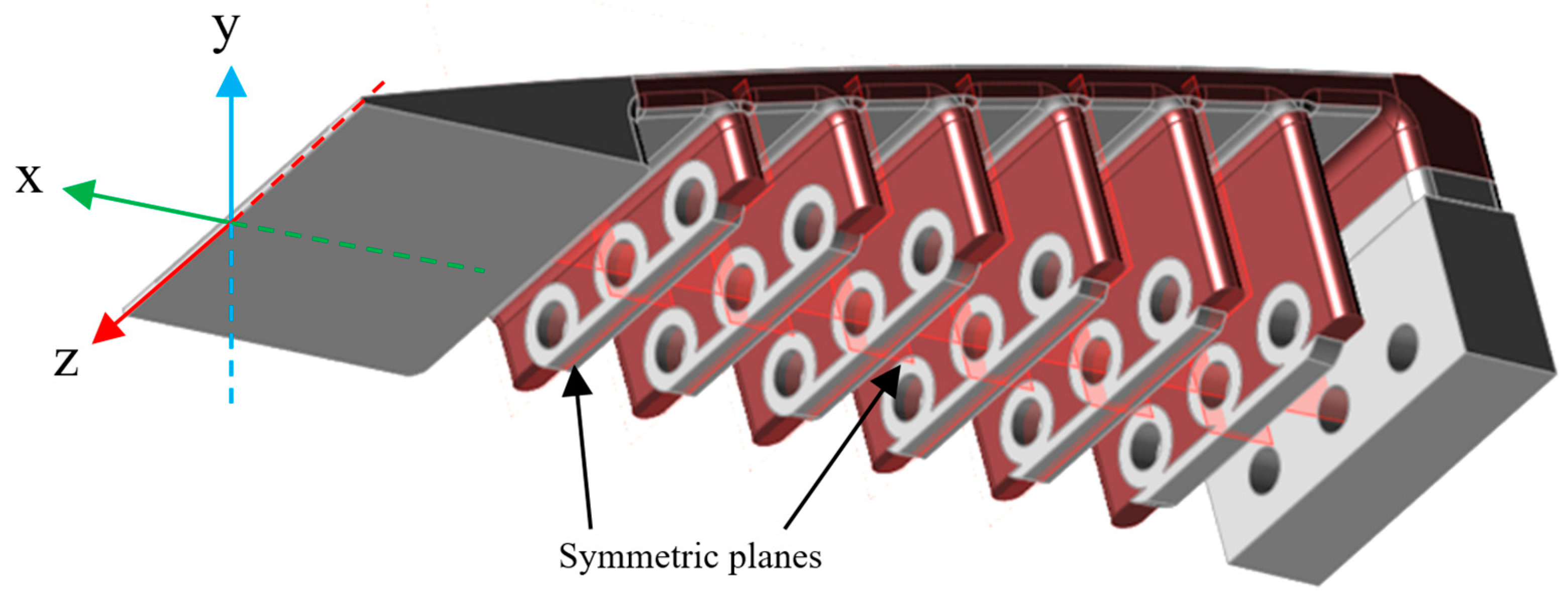
2.5. Boundary Conditions

The fixation of the ET rib to the wing box is performed with screws on the first solid tooth, which restricts any motion on the first tooth. Three cables pass through the interface (the interface of the wing box and the ET rib); they pass through the holes in the teeth all the way to the solid aluminium edge, where they are firmly fixed. Two configurations are set up for the finite element analysis of the cables. In the first analysis, the cables have a “sliding contact” with the teeth’s holes so that equal forces are applied to all teeth simultaneously. In the second configuration, the cables move freely within the holes, and “no contact” is defined between them and the teeth. In the sliding configuration, both the hole and the cable diameters are 3 mm, while in the no-contact configuration, the diameters of the holes are 4 mm and the diameters of the cables are 3 mm. Figure 4 shows the boundary conditions for both configurations.
As shown in Figure 3, two fixed supports are used for the boundary condition; the “root fixed supports” fix the first tooth (and the whole ET rib) to the wing box, while the “edge fixed supports” fix the elastic teeth to the solid edge part. These boundary conditions are the same for both sliding and no-contact configurations. However, the difference between the two configurations lies in the boundary condition between the cables and holes. The sliding contact and no-contact configurations are illustrated in yellow and gray colors, respectively (Figure 4A,B).
Once the fixation and interface contacts are determined, the final phase is the application of the desired forces. Each cable sustains a horizontal force of 250 N in the negative x-direction; the total force of 750 N is equally distributed among the three cables. The magnitude of the force was determined via our previous study [37], where a maximum displacement of 66 mm was found for the SMTE flap. The effect of aerodynamic forces was incorporated into the calculation of the driving force, thus ensuring that the applied force was sufficiently high to overcome aerodynamic resistance. Note that, for any other deformation magnitude, the applied force could vary.

2.5.1. Sliding Cable/Hole Configuration

By applying the force to the cables, the contours of structural parameters, including stress, strain, factor of safety, and displacement, are presented in Figure 5, which also indicates the maximum value of each parameter.
As seen in Figure 5A, the maximum von Mises stress on the ET rib reaches 58.94 MPa, which is lower than the structure’s tensile strength of 75 MPa (Table 1). The maximum local strain is equal to 0.01506, or 1.5% of its initial value, which occurs in the same area as the maximum von Mises stress, as seen in Figure 5B. The local strain value is less than 2%, which is within the elastic deformation limit. The safety level is calculated to ensure that the structure performs within the safety limits. The results show that the minimum Factor of Safety (FoS) is 1.3 at the place where maximum stress and strain occur (Figure 5C). This FoS is within the safety limits, which demonstrates the safety of the elastic structure.
In addition, the maximum attainable displacement of the edge can also be calculated, given the fact that it should respect the maximum displacement obtained from our previous study for increasing range [28], which was found to be 26 mm in the downward direction. The results show that using the given force (750N), a maximum deformation of 32.8 mm in the downward direction is obtained (Figure 5D), which is higher than 26 mm.

2.5.2. No-Contact Cable/Hole Configuration

An analysis like that of the sliding cable/hole configuration was conducted on the no-contact cable/hole configuration. It was found that for the no-contact configuration, the maximum von Mises stress reaches 105.3 MPa at the spot where the upper screws were located, and it was 44% higher than that of the sliding configuration. This increase was expected, as there was no contact or friction between the hole and the cable, and the inner teeth were not engaged in the deformation of the ET rib, since they had no friction against the cable and the applied force on the ET rib was directly exerted to the solid edge. Nevertheless, the results have shown similar values for the strain, which was equal to 0.01596 and only 5.6% higher than the sliding configuration strain. The minimum factor of safety is equal to 1.2, which guarantees the safety of the mechanism operation. Finally, considering the maximum vertical displacement of the ET rib after deformation, the no-contact configuration achieved higher vertical displacement than that of the sliding contact, reaching 39.53 mm (17% higher than with sliding contact). Figure 6 shows the maximum values obtained for each parameter, and Table 2 summarizes the results of both sliding and no-contact configurations.
A comparison was drawn between the two configurations, as shown in Table 3, expressed in terms of their advantages and disadvantages.
As indicated in Table 3, when structural stability and equal load distribution are considered, the sliding motion was a more suitable choice than the no-contact configuration, despite having frictional force that introduced resistance, a resistance that acts as a constraint against undesirable deformations. Therefore, the sliding configuration was selected for further study.
To ensure numerical accuracy, a grid independence study was conducted. The details of this study, including mesh refinement levels and their corresponding results, are provided in Appendix B.

3. Results and Discussion

3.1. Geometrical Modifications

Some geometrical modifications to the sliding configuration were required to improve the robustness of the structure, based on the results obtained in a structural analysis (Figure 4), especially to reduce the stress concentration around the screws, increase the reliability of ETM, and increase the maximum displacement of the elephant trunk (ET) rib. Two analyses are performed in this regard: 1. analysis of the teeth number and thickness, 2. analysis of the upper surface thickness. The first analysis aimed to find the optimum number of teeth for ETM along with their optimum thickness by considering the ETM weight and vertical displacement, and the second analysis was performed to improve the reliability and flexibility of the ETM by finding the best thickness for the upper surface. In the final step, the fixation of the ETM to the wing box was modified with the aim to reduce the stress concentration on the upper screws. Figure 7 depicts the initial ETM, in which the teeth thickness, upper surface thickness, and fixation to the wing box are specified.

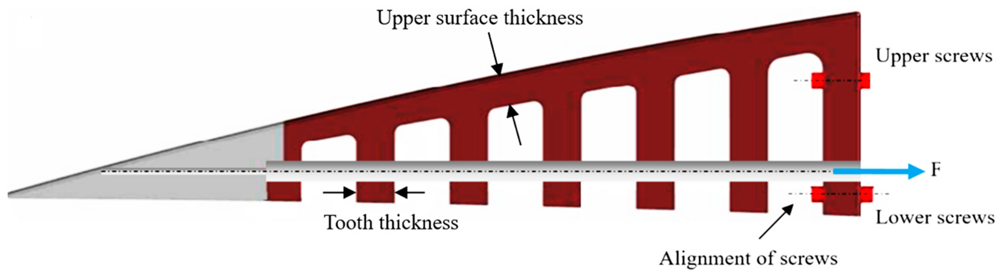
3.2. Analysis of the Teeth Number and Their Thickness

The teeth number and thickness have an important role in improving the structural characteristics of the ETM in terms of weight and maximum vertical displacement. As indicated in Section 2.5, having chosen the “sliding” over the “no-contact” configuration, the maximum vertical displacement was smaller than 32.8 mm. The analysis of the teeth’s number and thickness is aimed not only to increase the vertical displacement but also to reduce structural weight. For this purpose, different numbers of teeth, ranging from 3 to 10 teeth, are analyzed for three different thicknesses, ranging from 5 to 8 mm. The analysis is divided into two parts: 1. analysis of the teeth number, 2. analysis of the teeth thickness. In the first analysis, the best three tooth numbers were selected by considering the maximum force with the minimum factor of safety of 1.5. Table 4 shows the maximum force with the minimum factor of safety of 1.5 for different thicknesses and numbers of teeth.
As seen in Table 4, by increasing the teeth number from 3 to 10, the force magnitude, which has the minimum FoS of 1.5, increases. The best three teeth numbers were selected for different thicknesses. For example, for a teeth thickness of 5 mm, the best three teeth numbers, which have the highest applicable force, are 106.23 N, 106.24 N, and 107.66 N, corresponding to the teeth numbers 6, 7, and 10, respectively. The same criterion is used for the other teeth thicknesses (6 and 8 mm).
Once the best three tooth numbers are selected, the analysis is continued to find the best tooth thickness among 5, 6, and 8 mm. In this analysis, two parameters, including structural weight and maximum vertical displacement, are determined as the main criteria in obtaining the best tooth thickness. For this purpose, the weight and the vertical displacement of the three best tooth numbers (6, 7, and 10) were calculated (Table 5). As depicted in Table 5, the structural weight has a higher weighting factor than that of the vertical displacement.
As shown in Table 5, the tooth thickness of 5 mm has the best ranking among the 9 cases, which corresponds to a number of teeth equal to 6. Thus, for a 5 mm thickness and 6 teeth, the modified ETM design has a lower structural weight and a higher vertical displacement compared to its initial design, in which the number of teeth was 5 and the thickness was 8 mm.

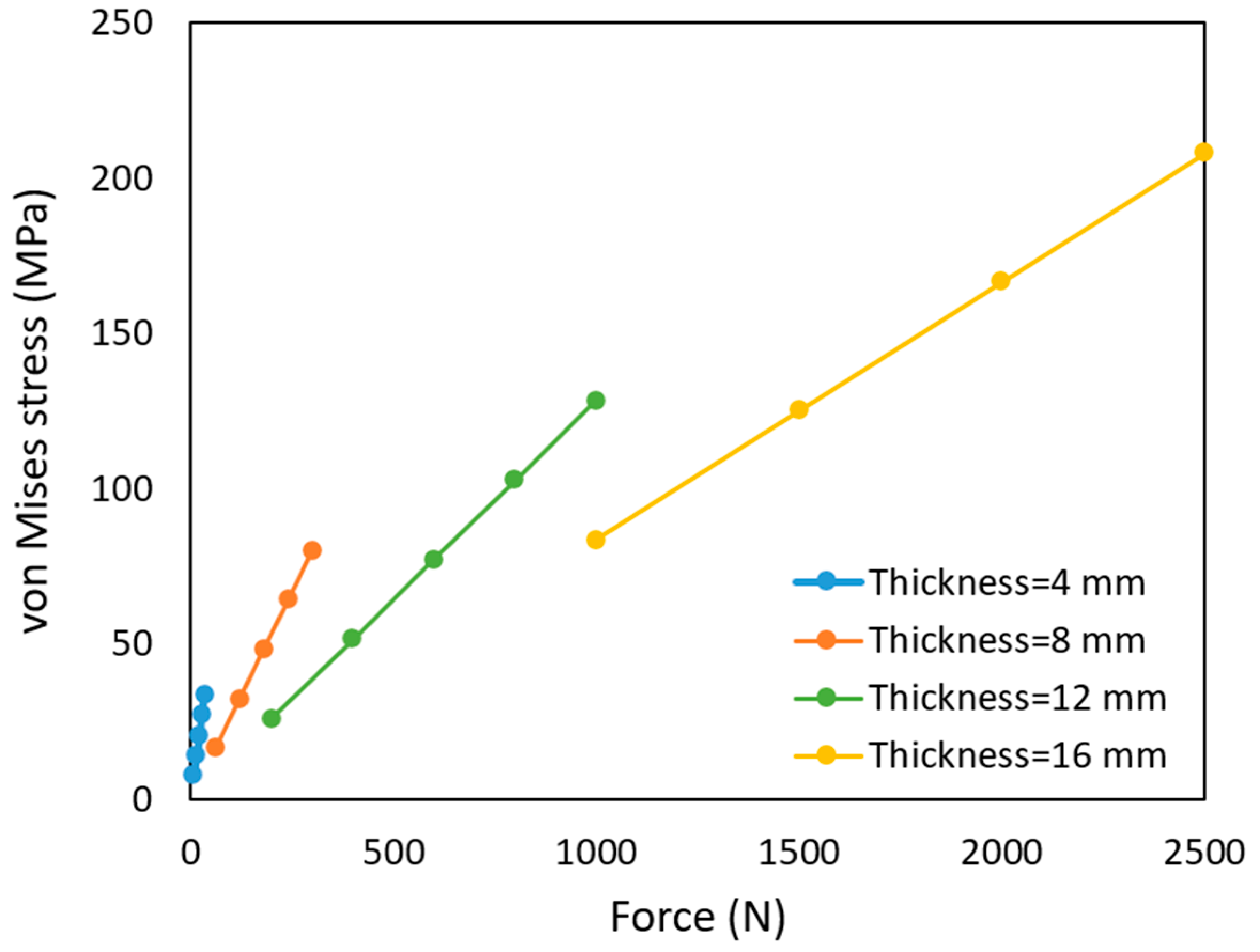
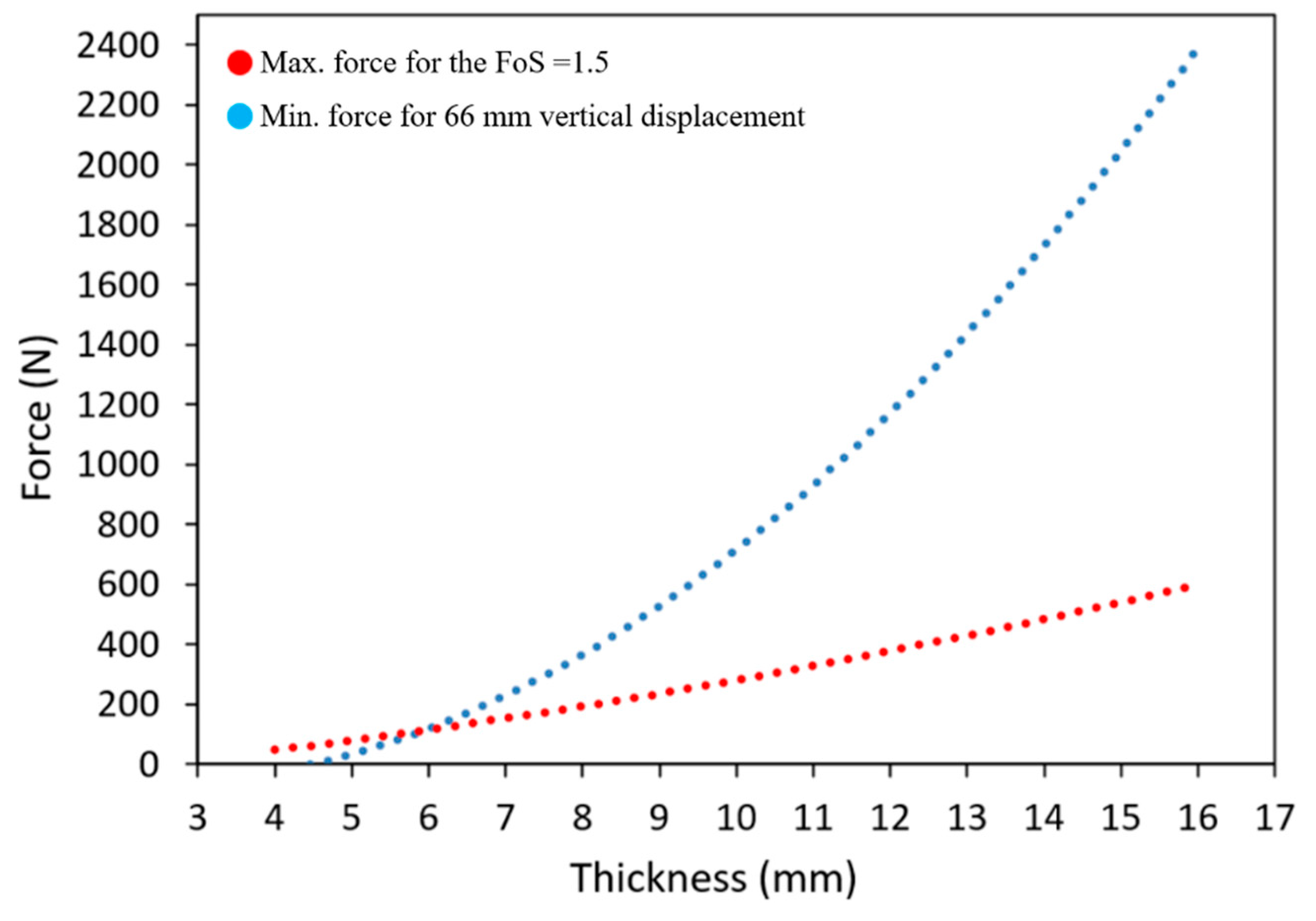
3.3. Analysis of the Upper Surface Thickness

The thickness calculated in this paper is the vertical component of the upper surface thickness, which connects the teeth to the ETM solid edge (Figure 7). This thickness is independent of the teeth thickness, and a different analysis than that of the teeth thickness is established to find the optimum thickness of the upper surface. This analysis is performed in the absence of the teeth in the ETM flexible part with an aim to find the influence of the thickness of the bending part and its best thickness with respect to ETM flexibility and reliability. Figure 8 shows the ETM without teeth for the analysis of the upper surface thickness. This thickness is aimed to be constant alongside the length of the elephant trunk rib.
As illustrated in Figure 8, a smaller moment (M2) is generated by the shorter lever arm in the section connecting the bending and solid edge parts, resulting in reduced influence on ETM morphing. In contrast, the section linking the fixation and bending parts experiences a higher moment (M1) due to its longer lever arm. Consequently, an appropriate upper surface thickness is necessary to compensate for this difference in moments (M1 and M2) and ensure the reliability and durability of the upper surface during ETM morphing.
Different thicknesses are studied, ranging from 4 mm to 16 mm. Their analysis requires the ETM to preserve its elastic deformation. With the elastic behavior being set, it is expected that both the displacement and the effort will be linearly proportional. For each thickness, the vertical displacement is set to be constant while applying different force magnitudes. With this assumption, several structural parameters, including factor of safety, von Mises stress, and structural weight, are calculated for each thickness. Table 6 indicates the values of these structural parameters for each thickness.
Table 6 indicates that by increasing the thickness, the force required to obtain the same magnitude of displacement also increases, which leads to an increase in the von Mises stress and weight of the whole ETM and a reduction in the factor of safety. For example, for the thicknesses of 4 mm and 16 mm, to obtain a displacement of approximately 62 mm, the required force increases from 35 N to 2500 N, von Mises stress increases from 33.6 MPa to 208.2 MPa, and the total ETM weight increases from 81 g to 201 g, while the factor of safety reduces from 2.2 to 0.4. To have a clear understanding of the values shown in Table 6, Figure 9 and Figure 10 show the variations of the vertical displacement and von Mises stress with the forces for different upper surface thicknesses.
Figure 9 and Figure 10 show that if displacement is constant, the increase in the von Mises stress and vertical displacement are linearly proportional to force magnitude, and this linear variation is sharp for lower thickness values, while as the thickness increases, the variation becomes mild. This linear variation could predict the force magnitude for each displacement and thickness.
In this study, the maximum desired displacement is 66 mm, which corresponds to the maximum vertical displacement obtained in our previous study [37]. To find the corresponding thickness for this vertical displacement, the ETM should meet the minimum factor of safety criteria, as mentioned in the Federal Airworthiness Regulation Part 25.303: “Unless otherwise specified, a factor of safety of 1.5 must be applied on the prescribed limit load, which are considered external loads on the structure” [49]. For this purpose, for upper surface thicknesses ranging from 4 mm to 16 mm, the maximum force for obtaining the minimum factor of safety of 1.5 was calculated, and then the minimum required force for obtaining the 66 mm displacement was also calculated. Figure 11 shows the variations of these forces with the thickness.
As shown in Figure 11, the two diagrams intersect at the thickness equal to 5.93 mm. This thickness value means that the ETM can morph up to 66 mm by having the minimum factor of safety of 1.5. Therefore, the upper surface thickness analysis determines the best thickness value, by which both the flexibility and reliability of the ETM increased. Figure 12 depicts the contour of the von Mises stress for ETM after morphing.

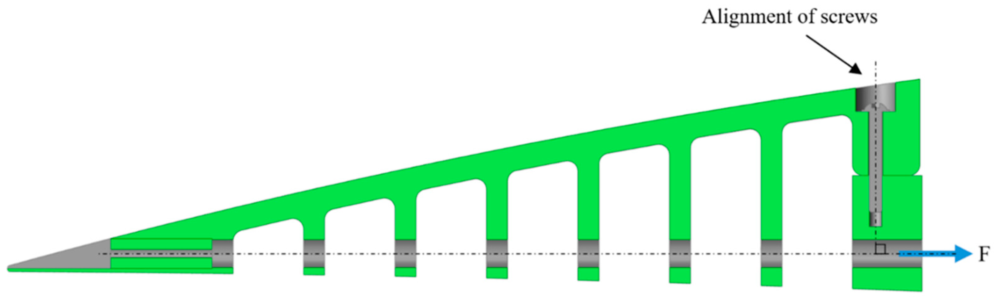
3.4. Modification of the ETM Fixation to the Wing Box

As shown in the initial design of ETM (Figure 7), due to the distance of the upper screws from the cables, when the ETM deforms in the downward direction, the upper screws sustain a higher force than that of the lower screws; therefore, higher stress concentrations are expected around the upper screws, as shown in Figure 5 and Figure 6. Therefore, instead of a horizontal fixation of the rib to the wing box, this rib was fixed using three screws at the top of the rib. This type of fixation reduces the stress concentration around the screws and moves it to another non-critical area. In the vertical fixation, no tensile force was expected to act on the screws, since the external force direction was perpendicular to the alignment of the screws.
Figure 13 shows the ETM modified design after finding the optimum number of teeth, their optimum thickness, the optimum upper surface thickness, and the suitable fixation to the wing box.
To avoid errors created by the singularities present in the structural design, round fillets were added around the edges of the teeth of the ET ribs to create a smooth continuity on the structures’ surfaces, which increases the safety of the structure by reducing stress concentration on the sharp edges. Stress concentration is related to the fillet radius by the following equation:
σ = K t F π r 2
where K t is the factor of intensity, r is the fillet radius, and F denotes the applied force on the fillet surface. According to Equation (3), the smaller the fillet, the higher the stress concentration, which is detrimental to the structure’s safety. Figure 14 shows the ETM after adding the fillets.

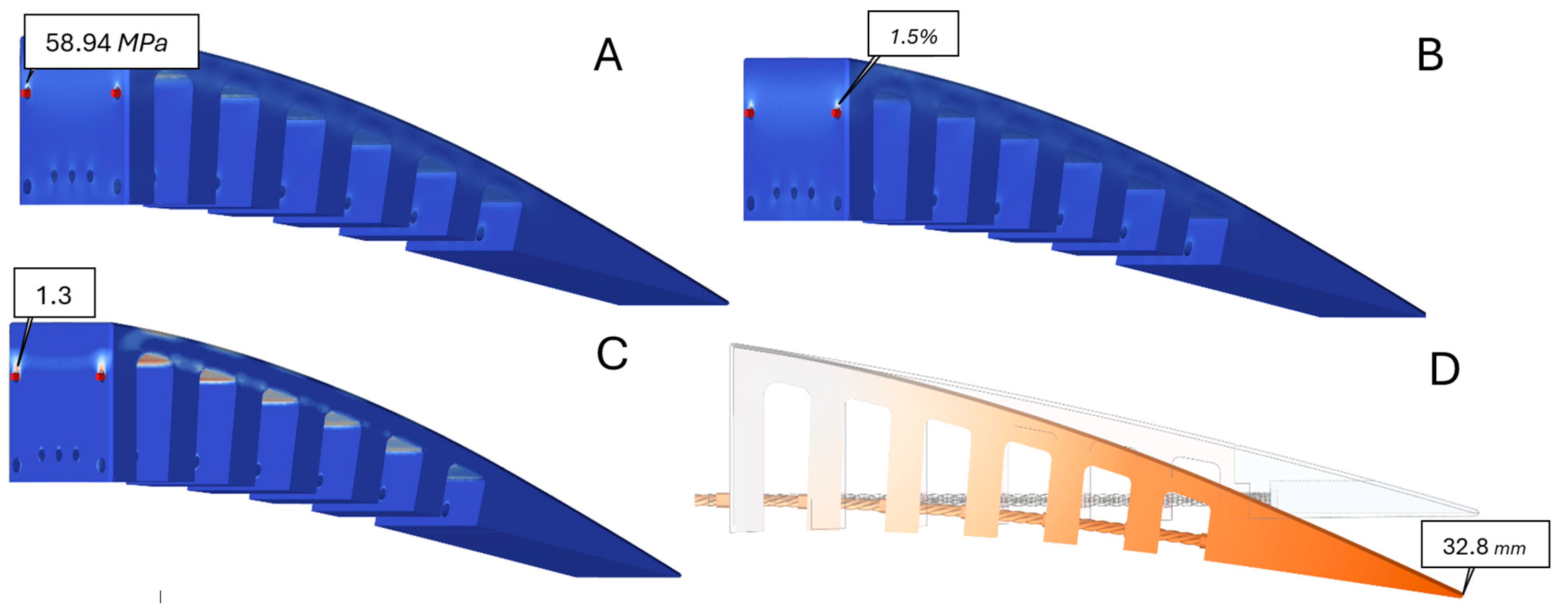
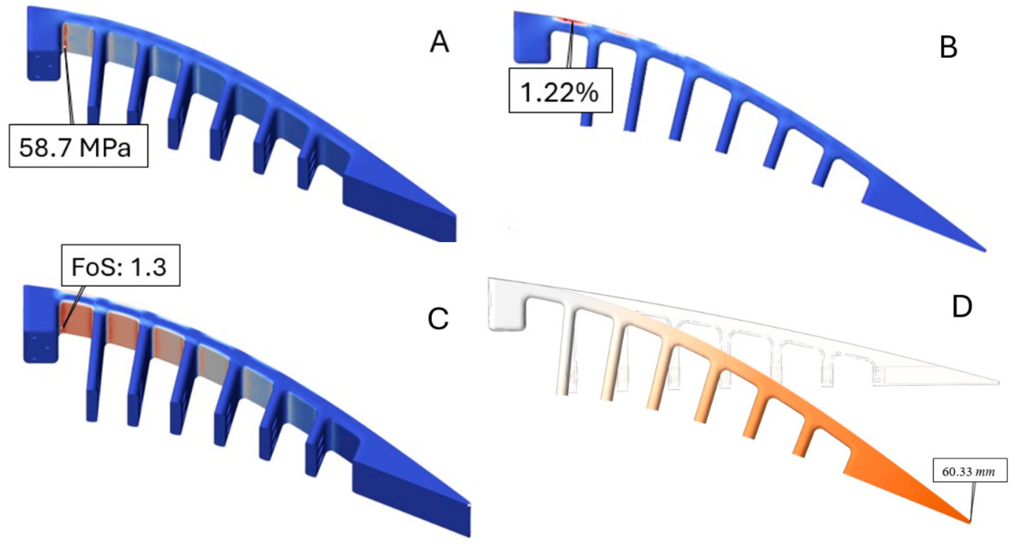
3.5. Results of the Structural Analysis

A structural analysis was performed for the modified structural design. Four parameters were analyzed: the von Mises stress, strain, factor of safety, and displacement. Figure 15 shows the results obtained from this analysis, in which the maximum values for stress, strain, and displacement, and the minimum value for the factor of safety are indicated. These values indicate that the structural parameters have been improved compared to the initial design.
Table 7 compares the results of structural parameters for the initial and modified structures. The results presented in Table 7 indicate that the maximum von Mises stress is reduced by 0.24 MP, and moved to an area other than that around the screws; strain is reduced by 19%, and vertical displacement by 45.63%, while the factor of safety remained unchanged. Therefore, the intended goals were accomplished by a geometrical modification, meaning that the stress concentration was both reduced and moved to a non-critical area, and the flexibility of the structure was increased. To further improve the structural parameters, particularly the structural weight, a topology optimization was performed and is described in the following section.

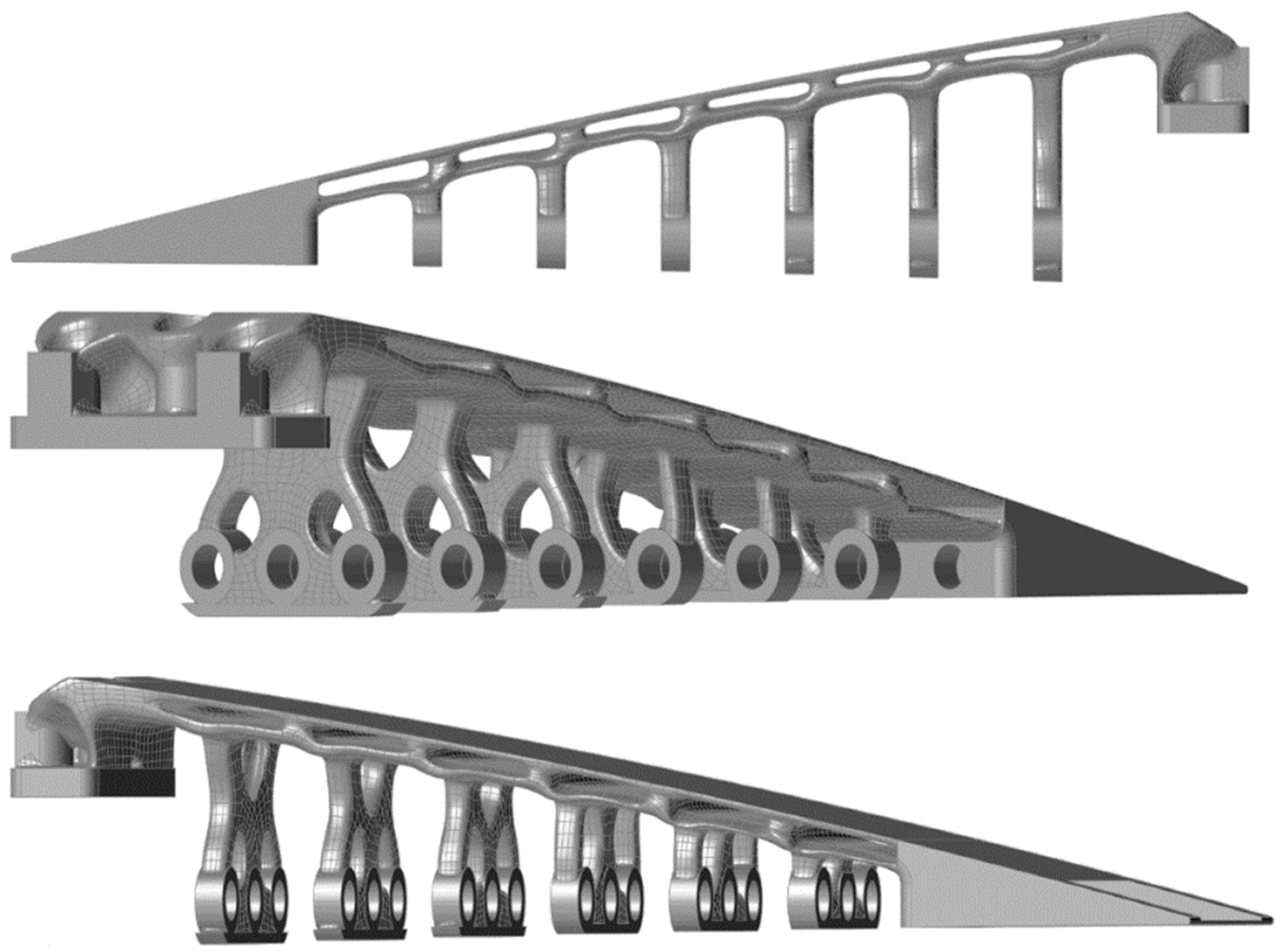
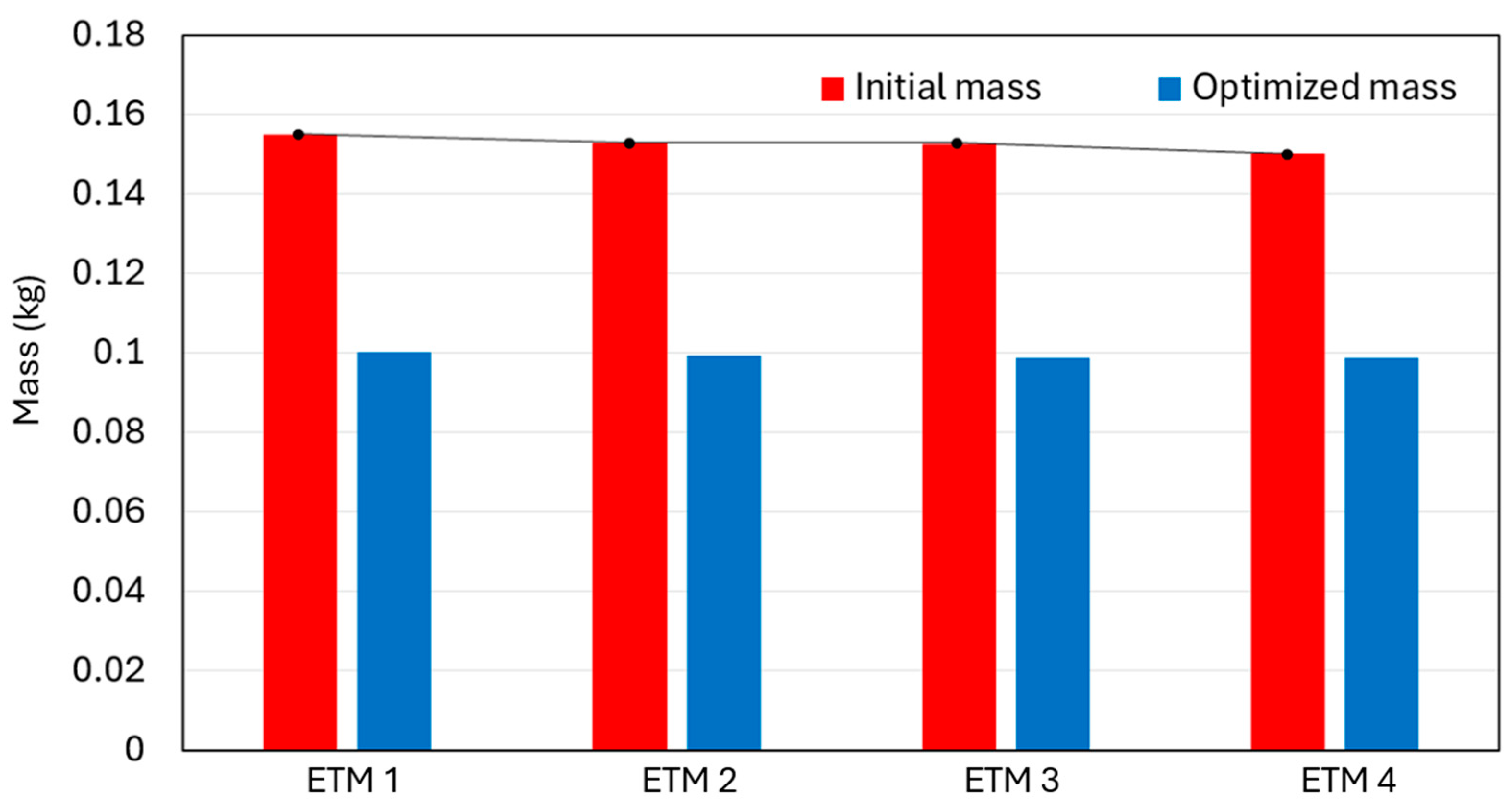
3.6. Topology Optimization

Topology optimization can be employed to design components with uniform stress distribution at every point, thereby reducing the weight-to-safety factor ratio [50,51]. This design approach is particularly employed in the automotive and aerospace sectors. In these fields, the focus on reducing weight is pushed to its limits, resulting in improved performance [52]. A multi-objective topology optimization was performed to find the optimum ETM design while respecting its constraints. The optimization was conducted using Altair Inspire, with the objectives of minimizing the structure weight and maximizing the stiffness. In the topology optimization, the material distribution was improved by strengthening the design in critical areas and by removing unnecessary mass to reduce the structural weight. In this process, multiple design spaces were considered; not only the solid edge, but also the interior of the upper surface and the space around the holes are included in these design spaces. Symmetric controls are also added to the design space to remove the mass symmetrically on each plane. There are eight symmetrical planes on the ETM in total, in which six symmetrical planes are located on the teeth (yz-plane) and two planes along the ETM length (xy-plane). Figure 16 shows the ETM with the specified design space (highlighted in red) and the symmetric control planes.
The stiffness is reversely proportional to the total structural compliance [53]; therefore, to increase the stiffness, the optimization tends to minimize the structural compliance, which is expressed as:
C = F T u
where C denotes the total structural compliance, F is the external force vector, and u is the displacement vector.
To respect the equilibrium equation in Equation (1), the stiffness or the internal forces within the structure should be in balance with external forces. Therefore, Equation (4) is rewritten in terms of stiffness as follows:
C = u T K u
By minimizing Equation (5), the objective function of stiffness maximization is satisfied. The second objective function, that is, the weight reduction, involves the material volume, V , in the design space, which can be expressed as a function of the material density, ρ . Since the analysis is using the FE method, the total volume is differentiated into finite elements, and it is written as:
V ( ρ ) = ρ e V e
where ρ e and V e denote the density and volume of each element, respectively.
The optimization is subject to several constraints that ensure the feasibility of the optimized topology. These constraints are 1-material distribution constraints correspond to objective functions in which the effective stiffness of each element is controlled as indicated in the following equation:
K ρ = ρ e p K e 0
where p is the penalization factor that ensures the intermediate density penalization, and K e 0 represents the stiffness matrix of each element when it is completely solid. 2-volume constraint, which limits the material removal to V * , where V * is the minimum allowable volume of the material, 3-density constraint, bounded between 0 and 1 (0 ρ e 1 ) , 4-symmetry constraint, which ensures symmetric material distribution in the design space, 5-the stiffness constraint that ensures the structure maintains its adequate stiffness by limiting it to a maximum allowable compliance, and finally, 6-equilibrium constraint function. Table 8 summarizes the entire optimization framework, including the objective functions and their corresponding constraints.
The optimization uses the combination of the Solid Isotropic Material with Penalization (SIMP) and the Optimality Criteria (OC) methods. The SIMP method distinguishes the solid from the void regions, while the penalization factor ( p ) modifies the material properties as a function of the density. This penalization factor is especially useful in solving large-scale problems. The combination of both algorithms ensures the robustness and efficiency of the optimization process.
The optimization started by initializing the design space with uniform material distribution ( ρ ₑ = 1). The SIMP method was used to calculate the material properties by interpolation among element densities, where the penalization factor p was set to 3 to suppress intermediate densities and provide a clear material distribution. At each iteration, the structural compliance was computed using a Finite Element (FE) solver, and the displacement field (u) was obtained by solving the equilibrium equation (Equation (1)). The sensitivity analysis was performed to compute the derivative of the compliance with respect to the density variables ( C ρ e ). Based on these sensitivities, the Optimality Criteria (OC) method updated the density values of each element using a heuristic update rule to satisfy the volume constraint. This iterative process continued until both convergence criteria—compliance and density field—were obtained below the prescribed thresholds (1% in this case).
Note that during the optimization, the cables were removed from the design space, and only the tooth-like elastic part was optimized. Regarding the mass reduction, different target values are specified for each part. For the teeth, starting from the solid edge part, 75, 73, 70, 66, 65, and 64% target mass reductions were specified, respectively. This percentage decrease was due to the relative proportion of the reference space in the total volume of the teeth. The fixation part and the bending part (upper surface) have a target value of 45% mass reduction. Figure 17 shows the ETM after topology optimization.
By expanding the design spaces to the ETM upper surface, unnecessary interior parts were removed from the structure. Moreover, more material was removed from the teeth, and the bulk shapes of the teeth were transformed into linkages supporting the holes, leading to even greater mass reduction. Figure 17 shows that unnecessary material has been removed from the ETM elastic bending part, which reduces the bending resistance and the effort required for the deformation. Table 9 indicates the improvements obtained from the ETM topology optimization.
The values presented in Table 9 show that most of the structural parameters were significantly improved. The maximum von Mises stress was reduced by 10.43%, the factor of safety was increased from 1.3 to 1.5, and the maximum vertical displacement increased by 8.6% (from 60.33 mm to 66.02 mm), thus indicating more structural flexibility on the optimized ETM. However, the maximum strain increased from 1.2% to 1.63% due to the hollow spaces on the upper bending part created after the optimization. Finally, the results obtained for the mass reduction indicated that the initial mass of 0.155 kg was reduced to 0.1 kg, signifying a reduction of 35.5%. Figure 18 shows the deformation of the ETM before and after the optimization.
A total number of four ETM ribs were used in the flap section of the UAS-S45 wing. These ETMs were identical, except for small differences in their heights due to the tapered characteristics of the wing, which gave an infinitesimal difference in the ETMs weight. Therefore, each ETM rib was optimized separately, and the mass reduction was unique for each ETM. Figure 19 shows the mass variations for each ETM rib.
The mass was reduced for each ETM. Considering one wing, a total mass of 0.214 kg was removed from all four ET ribs after topology optimization, which would be equivalent to a 4.2 N weight reduction for the whole UAS equipped with two wings.

3.7. Elephant Trunk Mechanism Integration on the UAS-S45 Wing Box
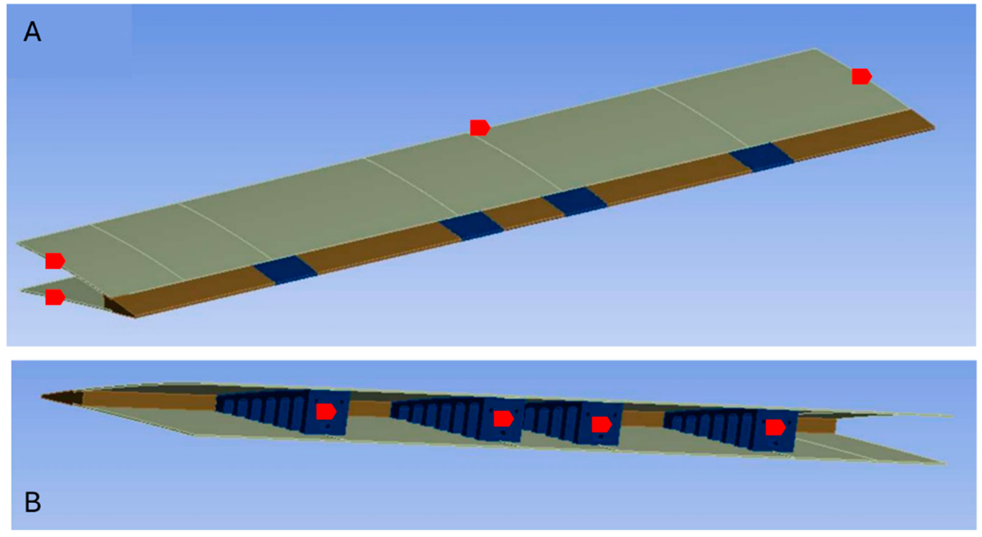
After the structural analysis and topology optimization on the ETMs, a number of four ETMs were designed on the Seamless Morphing Trailing Edge (SMTE) flap section. The distance between these ribs corresponded to the flap length, which was defined in our previous study [28]. Figure 20 shows the SMTE flap and its geometrical details, in which the elephant trunk mechanism was used with the aim to generate the required deformation (Figure 20B,C). Therefore, the four ETMs were located inside the morphing flap section, and the transition sections on the right and left sides of the SMTE flap were used to follow the deformations obtained from the ETMs (Figure 20B). The total length of the SMTE was 1 m, the section where the ETMs were embedded was equal to 0.735 of the total flap length (excluding transition sections), and 0.1325 m was allocated to each transition section.
To fix the ETMs on the wing box, they were screwed from the top, as shown in Figure 21. The advantage of this type of fixation was its reduced stress concentration around the screws, as noted in Section 3.4.
Figure 22 illustrates the orientation of the ETMs inside the SMTE flap. Four ETMs were embedded inside the SMTE flap section, excluding the transition sections. They were fixed to the solid spar along the span. Respecting the symmetric orientation, ETM 2 and ETM 3 were fixed in the center of the flap, while ETM 1 and ETM 4 were fixed at the beginning of the transition sections, as shown in Figure 22B.

3.8. Skin Analysis

In the final phase of this study, a skin analysis was performed with the aim to find the appropriate skin material corresponding to the requirements of the Seamless Morphing Trailing Edge (SMTE) flap, which has high flexibility. Figure 23 shows a schematic of a UAS-S45 wing section with the STME flap and the ETMs, where the flexible skin covers the whole flap section with the ETMs embedded within.
As seen in Figure 23, the skin covers a rectangular area on both the upper and lower surfaces of the wing. The analysis was performed by focusing on a section of the wing that contains the skin, which would reduce the computation time and cost. This approach requires establishing a suitable boundary condition corresponding to the actual constraints. The skin analysis was performed using the ANSYS 2021 R2 software. Figure 24 shows the computational domain and the boundary condition for the skin analysis.
As seen in Figure 24, the wing sections, which have no impact on the skin analysis, were eliminated; ETMs were considered as the supports for the upper and lower skins and were included in the analysis. The boundary condition used in this analysis requires the edges and surfaces specified in red color to have a fixed support during the analysis. In fact, in the actual wing, these areas (surfaces and edges) with fixed motion constraints are attached to the wing box. With these constraints, the only moving part of the wing was the trailing edge, where the downward morphing of the ETMs also deformed the skin.
To simulate the actuation of the morphing mechanism, a prescribed vertical displacement of 66 mm was applied at the trailing edge of the structure. This displacement corresponds to the maximum downward deflection produced by the Elephant Trunk Mechanisms (ETMs) during operation. The applied boundary condition was intended to replicate the deformation profile induced by the ETMs and assess the skin’s flexibility and conformity to the target morphing shape.
For the skin analysis, silicon rubber (silicon VMQ) was chosen due to its unique material properties in morphing wing applications. Table 10 depicts the silicon rubber properties as follows.
Given the nonlinear deformation characteristics of silicone rubber, a hyper-elastic material model was used for the skin analysis. Silicon rubber is a very soft and flexible material in terms of elongation and stretchability. In addition, long fatigue resistance is one of the unique characteristics of silicon rubber, which makes it a suitable choice for morphing wing application, where frequent deformation during flight demands a material with high fatigue resistance. Therefore, by performing repeated morphing, it can maintain its flexibility without significant material degradation. Considering the temperature effect, silicon rubber performs very well at various temperatures ranging from 60 ° C to + 200 ° C. For the UAS-S45, the ceiling altitude is 15,000 ft, where the temperatures could reach 20 ° C at cruise flight; nevertheless, silicon rubber still performs very well at this temperature, as mentioned above.
By choosing silicon rubber as the SMTE flap skin material, a skin analysis was performed. In this analysis, the most important factor was the deformation smoothness, especially on the lower side of the flap, where wavy deformations were very likely to occur due to the downward deformation. Figure 25 shows the skin deformation contours after SMTE flap deformation.
As shown in Figure 25, silicon rubber skin perfectly accomplishes the ETM’s morphing, especially on the transition parts. It was found that the upper surface skin (Figure 25B,C) had a very good surface smoothness after morphing, and there was no sign of distortion; however, Figure 25C shows some distortions on the wing lower surface skin after morphing. This behavior was expected, as the ETM downward deflection contracts the lower surface, and the skin contracts accordingly. This contraction issue on the lower surface could be easily solved by pre-tensioning the lower surface skin before attaching it to the ETMs, which means that the skin is stretched before attaching it to the ETMs, and once the morphing occurs, the lower surface contraction preserves the initial state of the skin; thus, the distortions will be eliminated on the lower surface.

4. Conclusions

This paper introduces the novel Elephant Trunk Mechanism (ETM) inspired by an elephant’s trunk. This ETM was structurally investigated in conjunction with a topology optimization to examine its reliability and feasibility for its application on the Seamless Morphing Trailing Edge (SMTE) flap. The promising aerodynamic results of the SMTE flap from our previous study [28] motivated us to perform this current study to further analyze it from a structural perspective. This novel morphing concept consisted of tooth-like elements whose contraction through a horizontal axial force by cables changed the trailing edge shape in the downward direction.
The static analysis was performed using the Finite Element Method (FEM). An analysis was first conducted to find a suitable connection type between the cables and the holes. A comparison between the two contact types revealed that the sliding contact configuration provided greater reliability in terms of stability, stress distribution, load transfer, and deformation feasibility.
Next, using the sliding contact boundary condition, the mechanism was structurally analyzed, and the results were further improved by geometrical modification. These modifications were analyzed in three ways: 1-analysis of finding the optimum number of teeth and their thicknesses, 2-upper surface thickness analysis, and finally, the analysis of the ETM fixation to the wing box. Following the ETMs’ structural modifications, the stress was reduced by 0.4%, and the stress concentration moved to a non-critical area; the maximum strain was reduced by 19%, and the ETM maximum vertical displacement increased by 45.63%, all of which improved the ETMs’ structural flexibility.
Using a suitable design space, a topology optimization was conducted with the objective of minimizing the structural weight. The optimization results showed that not only was the weight reduced, but the structural parameters were also improved. The optimization results showed that the maximum von Mises stress was reduced by 10.43%, while the factor of safety increased from 1.3 to 1.5, and the ETM maximum vertical displacement was increased by 8.6%. The mass reduction, which was the main objective of the topology optimization, was reduced by up to 35.5% compared to the initial structure mass, and a total weight reduction of 4.2 N was achieved for the whole UAS.
Finally, the four optimized ETMs were fixed on the SMTE flap to perform a skin analysis, in which silicon rubber was used as a base material due to its high fatigue life and flexibility. The results showed that the skin perfectly integrated with the ETM morphing, especially on the transition sections on the left and right sides for the SMTE flap.
In our next study, the SMTE flap equipped with ETMs and silicon rubber skin will be prototyped using a suitable actuation control system. The prototyped wing will be tested in a wind tunnel to validate the results obtained from this study.

Author Contributions

Conceptualization, M.H.N. methodology, M.H.N.; software, M.H.N., A.H., M.N.W. and C.N.; validation, M.H.N.; formal analysis, M.H.N. and A.H.; investigation, M.H.N., A.H., M.N.W. and C.N.; data curation, M.H.N.; writing—original draft preparation, M.H.N.; writing—review and editing, M.H.N. and R.M.B.; visualization, M.H.N. and R.M.B.; supervision, R.M.B.; project administration, M.H.N. and R.M.B.; funding acquisition, R.M.B. All authors have read and agreed to the published version of the manuscript.

Funding

This research received no external funding.

Data Availability Statement

The data presented in this study are available on request from the corresponding author.

Acknowledgments

We wish to express our profound gratitude to the Natural Sciences and Engineering Research Council of Canada (NSERC) for their invaluable funding of the Tier 1 Canada Research Chair in Aviation Modelling and Simulation Technology. Our heartfelt thanks also go to the dedicated team at Hydra Technologies in Mexico and the generous CREATE-UTILI Program for their financial support.

Conflicts of Interest

The authors declare no conflicts of interest.

Appendix A

The specifications of the Unmanned Aerial System (UAS-S45) are summarized in Table A1, and its configuration is illustrated in Figure A1.
Table A1. Specifications of Unmanned Aerial System UAS-S45.
SpecificationValue
Wing span6.11 m
Wing area2.72 m2
Total length3.01 m
Mean aerodynamic chord0.57 m
Empty weight57 kg
Maximum take-off Weight79.6 kg
Loitering airspeed55 knots
Service ceiling17,000 ft
Operational range120 km
Figure A1. Unmanned Aerial System UAS-S45 [38].
Aerospace 12 00381 g0a1

Appendix B

To ensure that the numerical results were independent of the mesh resolution, a grid independence study was conducted. Several mesh configurations with varying element sizes were tested, and their effects on key parameters, such as computation time, vertical displacement, and von Mises stress were analyzed. The relative errors of these parameters were also evaluated to determine the optimal mesh density. In this study, an element size of 1 mm was considered as the reference. Table A2 summarizes the results of the grid independence study.
Table A2. Results of grid independence study.
Element Size
(mm)
Run Time
(S)
Displacement
(mm)
Relative Error
%
Von Mises Stress
MPa
Relative Error
%
63259.324.8743.3926.85
44261.561.2852.2711.88
211662.170.3058.451.47
1.521862.240.1957.453.15
1.2536862.310.0858.800.88
172762.36-59.32-
A 5% margin error was set as the maximum admissible threshold for selecting the appropriate element size. As shown in Table A2, when the element size exceeds 2 mm, the relative error in von Mises stress surpasses 11.88%, which is very high. To balance computational efficiency and accuracy while maintaining a relative error below 5%, an element size of 2 mm was chosen for the structural analysis of ET due to its minimal relative errors and efficient computation time.

References

  1. Ameduri, S.; Concilio, A. Morphing wings review: Aims, challenges, and current open issues of a technology. Proc. Inst. Mech. Eng. Part C J. Mech. Eng. Sci. 2023, 237, 4112–4130. [Google Scholar] [CrossRef]
  2. Mrazova, M. Sustainable development-the key for green aviation. INCAS Bull. 2014, 6, 109–122. [Google Scholar]
  3. Khalid, M.; Juhany, K. Effects of blowing upon dynamic stability of blunt nosed re entry vehicles pitching in hypersonic flow. Aeronaut. J. 2024, 128, 547–558. [Google Scholar] [CrossRef]
  4. Bartley-Cho, J.D.; Wang, D.P.; Martin, C.A.; Kudva, J.N.; West, M.N. Development of high-rate, adaptive trailing edge control surface for the smart wing phase 2 wind tunnel model. J. Intell. Mater. Syst. Struct. 2004, 15, 279–291. [Google Scholar] [CrossRef]
  5. Kota, S.; Osborn, R.; Ervin, G.; Maric, D.; Flick, P.; Paul, D. Mission adaptive compliant wing–design, fabrication and flight test. In Proceedings of the RTO Applied Vehicle Technology Panel (AVT) Symposium, Lisbon, Portugal, 20–24 April 2009; pp. 1–18. [Google Scholar]
  6. Botez, R.M.; Koreanschi, A.; Gabor, O.S.; Tondji, Y.; Guezguez, M.; Kammegne, J.; Grigorie, L.; Sandu, D.; Mebarki, Y.; Mamou, M.; et al. Numerical and experimental transition results evaluation for a morphing wing and aileron system. Aeronaut. J. 2018, 122, 747–784. [Google Scholar] [CrossRef]
  7. Ameduri, S.; Concilio, A.; Dimino, I.; Pecora, R.; Ricci, S. AIRGREEN2—Clean Sky 2 Programme: Adaptive Wing Technology Maturation, Challenges and Perspectives. In Proceedings of the ASME 2018 Conference on Smart Materials, Adaptive Structures and Intelligent Systems, San Antonio, TX, USA, 10–12 September 2018. [Google Scholar]
  8. Liauzun, C.; Le Bihan, D.; David, J.-M.; Joly, D.; Paluch, B. Study of morphing winglet concepts aimed at improving load control and the aeroelastic behavior of civil transport aircraft. Aerosp. Lab 2018, 1–15. [Google Scholar] [CrossRef]
  9. Eguea, J.P.; Bravo-Mosquera, P.D.; Catalano, F.M. Camber morphing winglet influence on aircraft drag breakdown and tip vortex structure. Aerosp. Sci. Technol. 2021, 119, 107148. [Google Scholar] [CrossRef]
  10. Ajaj, R.; Friswell, M.; Saavedra Flores, E.; Little, O.; Isikveren, A. Span morphing: A conceptual design study. In Proceedings of the 53rd AIAA/ASME/ASCE/AHS/ASC Structures, Structural Dynamics and Materials Conference, Honolulu, HI, USA, 23–26 April 2012; p. 1510. [Google Scholar]
  11. Ismail, N.; Zulkifli, A.; Abdullah, M.; Basri, M.H.; Abdullah, N.S. Optimization of aerodynamic efficiency for twist morphing MAV wing. Chin. J. Aeronaut. 2014, 27, 475–487. [Google Scholar] [CrossRef]
  12. Mamou, M.; Mébarki, Y.; Khalid, M.; Genest, M.; Coutu, D.; Popov, A.; Sainmont, C.; Georges, T.; Grigorie, L.; Botez, R.; et al. Aerodynamic performance optimization of a wind tunnel morphing wing model subject to various cruise flow conditions. In Proceedings of the 27th International Congress of the Aeronautical Sciences ICAS, Nice, France, 19–24 September 2010; pp. 1–25. [Google Scholar]
  13. Kan, Z.; Li, D.; Shen, T.; Xiang, J.; Zhang, L. Aerodynamic characteristics of morphing wing with flexible leading-edge. Chin. J. Aeronaut. 2020, 33, 2610–2619. [Google Scholar] [CrossRef]
  14. Fereidooni, A.; Marchwica, J.; Leung, N.; Mangione, J.; Wickramasinghe, V. Development of a hybrid (rigid-flexible) morphing leading edge equipped with bending and extending capabilities. J. Intell. Mater. Syst. Struct. 2021, 32, 1024–1037. [Google Scholar] [CrossRef]
  15. Woods, B.K.S.; Friswell, M.I. Preliminary investigation of a fishbone active camber concept. In Proceedings of the ASME 2012 Conference on the Smart Materials, Adaptive Structures and Intelligent Systems, Stone Mountain, GA, USA, 19–21 September 2012; pp. 555–563. [Google Scholar]
  16. Woods, B.K.; Bilgen, O.; Friswell, M.I. Wind tunnel testing of the fish bone active camber morphing concept. J. Intell. Mater. Syst. Struct. 2014, 25, 772–785. [Google Scholar] [CrossRef]
  17. Shi, X.; Yang, Y.; Wang, Z.; Zhang, S.; Sun, X.; Feng, W. Design and shape monitoring of a morphing wing trailing edge. Aerospace 2023, 10, 127. [Google Scholar] [CrossRef]
  18. Cheng, G.; Ma, T.; Yang, J.; Chang, N.; Zhou, X. Design and Experiment of a Seamless Morphing Trailing Edge. Aerospace 2023, 10, 282. [Google Scholar] [CrossRef]
  19. Dimino, I.; Flauto, D.; Diodati, G.; Concilio, A.; Pecora, R. Actuation system design for a morphing wing trailing edge. Recent Pat. Mech. Eng. 2014, 7, 138–148. [Google Scholar] [CrossRef]
  20. Campanile, L.; Sachau, D. The belt-rib concept: A structronic approach to variable camber. J. Intell. Mater. Syst. Struct. 2000, 11, 215–224. [Google Scholar] [CrossRef]
  21. Sinapius, M.; Monner, H.P.; Kintscher, M.; Riemenschneider, J. DLR’s morphing wing activities within the European network. Procedia IUTAM 2014, 10, 416–426. [Google Scholar] [CrossRef]
  22. Wang, Q.; Xu, Z.; Zhu, Q. Structural design of morphing trailing edge actuated by SMA. Front. Mech. Eng. 2013, 8, 268–275. [Google Scholar] [CrossRef]
  23. Wu, R.; Soutis, C.; Zhong, S.; Filippone, A. A morphing aerofoil with highly controllable aerodynamic performance. Aeronaut. J. 2017, 121, 54–72. [Google Scholar] [CrossRef]
  24. Dumont, A. Adjoint-based aerodynamic shape optimization applied to morphing technology on a regional aircraft wing. In Morphing Wing Technologies; Elsevier: Amsterdam, The Netherlands, 2018; pp. 145–174. [Google Scholar]
  25. Li, B.; Li, G. Analysis and optimization of a camber morphing wing model. Int. J. Adv. Robot. Syst. 2016, 13. [Google Scholar] [CrossRef]
  26. Nguyen, N.T.; Livne, E.; Precup, N.; Urnes, J.M.; Nelson, C.; Ting, E.; Lebofsky, S. Experimental investigation of a flexible wing with a variable camber continuous trailing edge flap design. In Proceedings of the 32nd AIAA Applied Aerodynamics Conference, Atlanta, GA, USA, 16–20 June 2014; p. 2441. [Google Scholar]
  27. Di Matteo, N.; Guo, S. Morphing trailing edge flap for high lift wing. In Proceedings of the 52nd AIAA/ASME/ASCE/AHS/ASC Structures, Structural Dynamics and Materials Conference, Denver, CO, USA, 4–7 April 2011; p. 2164. [Google Scholar]
  28. Concilio, A.; Dimino, I.; Pecora, R.; Ciminello, M. Structural design of an adaptive wing trailing edge for enhanced cruise performance. In Proceedings of the 24th AIAA/AHS Adaptive Structures Conference, San Diego, CA, USA, 4–8 January 2016. [Google Scholar]
  29. Takahashi, H.; Yokozeki, T.; Hirano, Y. Development of variable camber wing with morphing leading and trailing sections using corrugated structures. J. Intell. Mater. Syst. Struct. 2016, 27, 2827–2836. [Google Scholar] [CrossRef]
  30. Barbarino, S.; Dettmer, W.G.; Friswell, M.I. Morphing trailing edges with shape memory alloy rods. In Proceedings of the 21st International Conference on Adaptive Structures and Technologies (ICAST), University Park, PA, USA, 4–6 October 2010. [Google Scholar]
  31. Kota, S.; Flick, P.; Collier, F.S. Flight testing of flexfloiltm adaptive compliant trailing edge. In Proceedings of the 54th AIAA Aerospace Sciences Meeting, San Diego, CA, USA, 4–8 January 2016; p. 0036. [Google Scholar]
  32. Negahban, M.H.; Bashir, M.; Priolet, C.; Botez, R.M. Novel twist morphing aileron and winglet design for UAS control and performance. Drones 2024, 8, 392. [Google Scholar] [CrossRef]
  33. Bourchak, M.; Ajaj, R.; Flores, E.S.; Khalid, M.; Juhany, K. Optimum design of a PID controller for the adaptive torsion wing. Aeronaut. J. 2015, 119, 871–889. [Google Scholar] [CrossRef]
  34. Du, S.; Ang, H. Design and feasibility analyses of morphing airfoil used to control flight attitude. Stroj. Vestn.-J. Mech. Eng. 2012, 58, 46–55. [Google Scholar] [CrossRef]
  35. Khorrami, M.R.; Lockard, D.P.; Moore, J.B.; Su, J.; Turner, T.L.; Lin, J.C.; Taminger, K.M.; Kahng, S.K.; Verden, S.A. Elastically Deformable Side-Edge Link for Trailing-Edge Flap Aeroacoustic Noise Reduction. U.S. Patent 8,695,925, 15 April 2014. [Google Scholar]
  36. Woods, B.K.; Parsons, L.; Coles, A.B.; Fincham, J.H.; Friswell, M.I. Morphing elastically lofted transition for active camber control surfaces. Aerosp. Sci. Technol. 2016, 55, 439–448. [Google Scholar] [CrossRef]
  37. Negahban, M.H.; Bashir, M.; Traisnel, V.; Botez, R.M. Seamless morphing trailing edge flaps for UAS-S45 using high-fidelity aerodynamic optimization. Chin. J. Aeronaut. 2024, 37, 12–29. [Google Scholar] [CrossRef]
  38. Hydra Technologies. UAS-S45 Baalam. Available online: https://www.hydra-technologies.com/s45 (accessed on 19 April 2025).
  39. Communier, D.; Botez, R.M.; Wong, T. Design and validation of a new morphing camber system by testing in the price—Païdoussis subsonic wind tunnel. Aerospace 2020, 7, 23. [Google Scholar] [CrossRef]
  40. Negahban, M.H.; Bashir, M.; Botez, R.M. Free-form deformation parameterization on the aerodynamic optimization of morphing trailing edge. Appl. Mech. 2023, 4, 304–316. [Google Scholar] [CrossRef]
  41. Negahban, M.H.; Bashir, M.; Botez, R.M. Aerodynamic optimization of a novel synthetic trailing edge and chord elongation morphing: Application to the UAS-S45 airfoil. In Proceedings of the AIAA SCITECH 2023 Forum, National Harbor, MD, USA & Online, 23–27 January 2023; p. 1582. [Google Scholar]
  42. Negahban, M.H.; Bashir, M.; Botez, R.M. Impact of Free-Form Deformation Control Points on the Optimization of the UAS-S45. In New Technologies and Developments in Unmanned Systems, Proceedings of the International Symposium on Unmanned Systems and the Defense Industry, Madrid, Spain, 30 May–1 June 2022; Springer: Cham, Switzerland, 2023; pp. 21–27. [Google Scholar]
  43. Smith, K.K.; Kier, W.M. Trunks, tongues, and tentacles: Moving with skeletons of muscle. Am. Sci. 1989, 77, 28–35. [Google Scholar]
  44. Liang, Y.; McMeeking, R.; Evans, A. A finite element simulation scheme for biological muscular hydrostats. J. Theor. Biol. 2006, 242, 142–150. [Google Scholar] [CrossRef]
  45. Yang, J.; Pitarch, E.P.; Potratz, J.; Beck, S.; Abdel-Malek, K. Synthesis and analysis of a flexible elephant trunk robot. Adv. Robot. 2006, 20, 631–659. [Google Scholar] [CrossRef]
  46. Available online: https://stock.adobe.com/ca/images/ct-scan-of-an-elephants-trunk-detailing-muscular-and-tissue-structure/806136007?prev_url=detail (accessed on 5 June 2024).
  47. He, P.; Mader, C.A.; Martins, J.R.; Maki, K.J. Dafoam: An open-source adjoint framework for multidisciplinary design optimization with openfoam. AIAA J. 2020, 58, 1304–1319. [Google Scholar] [CrossRef]
  48. He, P.; Mader, C.A.; Martins, J.R.; Maki, K. An object-oriented framework for rapid discrete adjoint development using OpenFOAM. In Proceedings of the AIAA Scitech 2019 Forum, San Diego, CA, USA, 7–11 January 2019; p. 1210. [Google Scholar]
  49. Federal Aviation Administration. 1970. Available online: https://www.ecfr.gov/current/title-14/part-25/section-25.303 (accessed on 10 August 2024).
  50. Beccari, C.V.; Ceruti, A.; Chudy, F. From Topological Optimization to Spline Layouts: An Approach for Industrial Real-Wise Parts. Axioms 2025, 14, 72. [Google Scholar] [CrossRef]
  51. Bacciaglia, A.; Ceruti, A.; Ciccone, F.; Liverani, A. Topology optimization for thin-walled structures with distributed loads. In Advances on Mechanics, Design Engineering and Manufacturing IV, Proceedings of the International Joint Conference on Mechanics, Design Engineering & Advanced Manufacturing, Ischia, Italy, 1–3 June 2022; Springer: Cham, Switzerland, 2022; pp. 1042–1054. [Google Scholar]
  52. Bacciaglia, A.; Ceruti, A.; Liverani, A. Surface smoothing for topological optimized 3D models. Struct. Multidiscip. Optim. 2021, 64, 3453–3472. [Google Scholar] [CrossRef]
  53. Daynes, S. High stiffness topology optimised lattice structures with increased toughness by porosity constraints. Mater. Des. 2023, 232, 112183. [Google Scholar] [CrossRef]
Figure 1. CT scan of an elephant’s trunk mechanism [46].
Aerospace 12 00381 g001
Figure 2. The bio-inspired elephant trunk mechanism for morphing trailing edge actuation.
Aerospace 12 00381 g002
Figure 3. Geometrical dimensions of the SMTE flap on the UAS-S45 wing in the aerodynamic study.
Aerospace 12 00381 g003
Figure 4. Illustration of boundary conditions for (A) sliding contact and (B) no contact between cables and holes.
Aerospace 12 00381 g004
Figure 5. Contours of (A) Von Mises stress, (B) strain, (C) factor of safety, and (D) displacement for sliding configuration indicating maximum values for each parameter.
Aerospace 12 00381 g005
Figure 6. Contours of (A) von Mises stress, (B) strain, (C) factor of safety, and (D) displacement for no-contact configuration indicating maximum values for each parameter.
Aerospace 12 00381 g006
Figure 7. Initial ETM design.
Aerospace 12 00381 g007
Figure 8. Schematics of the ETM without teeth for the analysis of the upper surface thickness.
Aerospace 12 00381 g008
Figure 9. Variation in the vertical displacement with the force magnitude for different upper surface thicknesses.
Aerospace 12 00381 g009
Figure 10. Variation in the von Mises stress with the force magnitude for different upper surface thicknesses.
Aerospace 12 00381 g010
Figure 11. Force variation for different upper surface thicknesses.
Aerospace 12 00381 g011
Figure 12. Maximum/minimum von Mises stress on the ETM after morphing with an optimum upper surface thickness.
Aerospace 12 00381 g012
Figure 13. Modified design of ETM.
Aerospace 12 00381 g013
Figure 14. Elephant trunk rib with filleted edges.
Aerospace 12 00381 g014
Figure 15. Contours of (A) von Mises stress, (B) strain, (C) factor of safety, and (D) displacement.
Aerospace 12 00381 g015
Figure 16. Illustration of the design space for topology optimization and the symmetrical planes.
Aerospace 12 00381 g016
Figure 17. Schematics of the optimized topology of the Elephant Trunk Mechanism (ETM) from different views.
Aerospace 12 00381 g017
Figure 18. Maximum displacement of ET rib, (A) before and (B) after topology optimization.
Aerospace 12 00381 g018
Figure 19. Mass variations for each ETM before (red) and after (blue) topology optimization.
Aerospace 12 00381 g019
Figure 20. Schematics of the SMTE flap: (A) top view, (B) back view, (C) side view after deformation.
Aerospace 12 00381 g020
Figure 21. Schematics of the ETM fixation to the UAS-S45 wing box.
Aerospace 12 00381 g021
Figure 22. Installation of the four ETMs on the main wing box of the UAS-S45: (A) top view, (B) side view, (C) isometric view.
Aerospace 12 00381 g022
Figure 23. Schematics of a UAS-S45 wing section with the STME flap, ETMs, and flexible skin.
Aerospace 12 00381 g023
Figure 24. Computational domain and boundary conditions for the skin analysis: (A) exterior view, (B) interior view.
Aerospace 12 00381 g024
Figure 25. Deformation contours of the silicon rubber skin: (A) isometric view, (B) rear view, (C) upper surface, (D) lower surface.
Aerospace 12 00381 g025
Table 1. Material properties for the Elephant Trunk Mechanism (ETM).
PartMaterialYoung’s Modulus (MPa)Poisson’s RatioDensity
(kg/m3)
Yield Strength
(MPa)
Elastic tooth-like partNylon29600.41114075
Solid edgeAluminium70,0000.33270040
CablesHigh Carbon Steel200,0000.297870375
Table 2. Summary of the results of structural analysis for both types of cable/hole configurations.
Cable/Hole Contact TypeMax. Von Mises Stress
(MPa)
Max. Strain
%
Min. FoSMax. Displacement
(mm)
Sliding58.941.51.332.8
No contact105.31.61.239.53
Table 3. Advantages and disadvantages of the sliding and no-contact configurations.
Contact TypeAdvantagesDisadvantages
Sliding
  • Higher stability
  • More uniform load distribution
  • Lower stress
  • No undesirable deformation due to frictional forces
  • Limited flexibility due to friction
No-contact
  • More flexibility and freedom.
  • Reduced frictional forces on cables
  • More simple design
  • Less support and stability
  • Non-uniform load distribution
  • Undesired deformations of ET rib
Table 4. Maximum applied force for different thicknesses and numbers of teeth.
Number of TeethMaximum Force with the Factor of Safety of 1.5 (N)
Tooth Thickness (mm)
568
3100.92106.80105.11
4101.55107.40106.87
5104.84108.34109.75
6106.23108.36108.25
7106.24110.54109.40
8105.87108.40110.26
9106.21109.54111.27
10107.66112.10109.94
Table 5. The structural weight and vertical displacement of ETM for the three best teeth numbers.
Tooth Thickness (mm)Weighting Factor
568
Number of Teeth671067106710
Structural Weight (g)1501581841701912012082222353
Score272418211512963
Vertical Displacement (mm)51.450.1475046.445.943.541.839.32
Score18161214108642
Total score45403035252015105
Ranking124356789
Table 6. Variations of structural parameters for different upper surface thicknesses.
Thickness
(mm)
Force
(N)
Displacement (mm)FoSVon Mises Stress
(MPa)
Weight
(g)
43562.492.233.681
2850.352.827.1
2138.213.620.6
1426.075.314.1
713.939.87.6
830062.390.980.1122
24051.571.264.1
18038.751.648.2
12025.932.332.3
6013.114.616.3
12100062.940.6128.4162
80050.370.7102.8
60037.811.077.1
40025.241.551.5
20012.682.925.9
16250063.480.4208.2201
200054.000.5166.6
150040.520.6125.1
100027.030.983.5
50013.551.842.0
Table 7. Comparison of the structural parameters of the initial and modified structures.
Max. Von-Mise Stress (MPa)Max. Strain%Min. Factor of SafetyMax. Displacement
(mm)
Initial model58.941.511.332.8
Modified model58.71.221.360.33
Table 8. Multi-objective topology optimization framework.
Function/VariableDescription
Objective functions
Min.  C = u T K u
Min.  V ( ρ ) = ρ e V e
minimization of structural compliance
minimization of weight
Subject to:
K ρ u = F Equilibrium constraint function
K ρ = ρ e p K e 0 Material distribution constraint
ρ e V e V * Volume constraint
0 ρ e 1    e Density constraint
ρ i j k = ρ i j ( k ) ( i , j , k ) Symmetry constraint
C ρ C m a x Stiffness constraint
Table 9. Comparison of the structural parameters of the ETM before and after optimization.
Max. Von Mises Stress (MPa)Max. Strain%Min. FoSMax. Vertical Displacement (mm)Mass (kg)
Initial ETM58.71.21.360.330.155
Optimized ETM52.581.631.566.020.100
Table 10. Material properties of the silicon rubber.
Young’s Modulus
(MPa)
Poisson RatioTensile Yield Strength
(MPa)
Density
(kg/m3)
170.510.41230
Disclaimer/Publisher’s Note: The statements, opinions and data contained in all publications are solely those of the individual author(s) and contributor(s) and not of MDPI and/or the editor(s). MDPI and/or the editor(s) disclaim responsibility for any injury to people or property resulting from any ideas, methods, instructions or products referred to in the content.

