1. Introduction
As part of the transport sector, aviation contributes significantly to the anthropogenic greenhouse effect [
1]. The Advisory Council for Aviation Research and Innovation in Europe (ACARE) has therefore set ambitious goals for reducing emissions [
2]. This increases the need to develop more sustainable aircraft. The new generation of aircraft not only aims to be more efficient but also explores alternative energy carriers and propulsion architectures, such as hydrogen fuel cell propulsion [
3] or hybrid electric propulsion [
4]. For this reason, the aircraft pre-design activities can not only rely on established methods, which are based on statistical data and previous knowledge of the design team. Nevertheless, the incorporation of the effects of unconventional propulsion architectures from the start of the design process is critical in order to minimize development risks. This incorporation is often obstructed by the complexity of the integration and the time demand to instantiate different disciplinary specific models in the design process [
5].
One means to support the collaborative aircraft design process can be Multidisciplinary Design Analysis and Optimization (MDAO) techniques. An example of these techniques is described by Walther et al. [
6] from a disciplinary perspective. Based on experience from aircraft design projects in academia and industry, four fundamental aspects for integration activities during the collaborative aircraft design process are identified: A central source of truth for data exchange, a process integration framework, system architecting capabilities and disciplinary analysis tools and competences. While all aspects contribute to a successful design process, this paper focuses in particular on the central data model. Establishing standardized data interfaces ensures that all partners interpret the data correctly and work with consistent models. This is a prerequisite for a robust and efficient data transfer between decentralized and heterogeneous teams. A widely used central data schema for aircraft design is the Common Parametric Aircraft Configuration Schema (CPACS), which has been applied in various research projects [
7,
8,
9]. For about two decades, CPACS has been expanded and improved covering classical aircraft design disciplines such as conceptual aircraft design, structural design or aerodynamic design, among many others [
10].
In contrast to the aforementioned disciplines, the use of CPACS as central data schema for MDAO processes for on-board systems (OBSs) is not widely established, since systems were so far only represented by generic shapes (cone, sphere, cube and cylinder), without connections or futher details. Nevertheless, it has been applied to a certain extent in different studies. Fioriti et al. [
11] instantiate the OBS discipline in an MDAO workflow to investigate the effect of different levels of integration. As data model of the MDAO process, a modified CPACS file is used storing information on OBS masses, volumes and power off-takes [
12]. Another approach based on CPACS is conducted by Mohan et al. [
13] for a systems integration framework for a hybrid-electric commuter aircraft. Therefore, the CPACS file is is customized to store system-level parameters and the system architecture at multiple level of granularity reaching down to component-level descriptions within the non-standardized (tool-specific) section of the data schema. Jeyaraj et al. [
14] aim to link Model-Based System Engineering (MBSE) and MDAO in the scope of architecting aircraft systems. Architectures are modeled in an MBSE environment using functional, logical and physical parameters that are extracted into a custom CPACS file and further processed in an MDAO workflow. These applications reflect a wide range from a functional/logical representation to a geometric/physical representation. A unified and standardized system specification that could bridge the gap between these representations is, to the best of the authors’ knowledge, not available in the literature.
To fill this gap, this paper introduces a comprehensive system definition for the CPACS data schema, which is structured as follows:
Section 2 outlines the main aspects of the CPACS data schema and discusses related system representations. Based on this background, the concept of a new system definition is described in detail in
Section 3. To validate the corresponding schema, the capabilities and advantages of the new schema definition are demonstrated by disciplinary experts in two application examples in
Section 4. The application cases represent a conventional on-board system design, as well as an alternative fuel cell propulsion system.
2. Background
Collaborative aircraft design is characterized as a multidisciplinary and iterative process due to the interrelations among the involved disciplines, as described by Moerland et al. [
15]. Typically, the process requires several design cycles with an increasing level of fidelity. During the execution of the process, engineering routines are applied by the different disciplines within a collaborative integration framework. This can be facilitated and automated using a standardized central data model. Focusing on this aspect of the design process, this section provides the general description of CPACS. Additionally, the features of selected system representations are discussed, which can be related to the new system definition within the data model.
2.1. General Description of CPACS
CPACS is an open-source hierarchical data model based on eXtensible Markup Language (XML). The first ideas for the development of CPACS go back to the year 2004, when the research project Technology Integration for the Virtual Aircraft (TIVA) was started to develop and implement methods and tools for collaborative aircraft design. This included the development of lCPACS as the central data exchange format; the associated software library for XML reading and parsing, called TiXI [
16]; and the XML geometry library, called TiGL [
17]; as well as an integration platform to connect the tools of experts at different locations in a network [
10]. Since then, CPACS has established itself as a de facto standard in scientific aircraft design and technology assessment in Germany and is increasingly used in the international aerospace community [
8].
The basic idea of CPACS is that disciplinary experts and their tools “speak a common language” by connecting to a standardized central data model instead of having to coordinate individual data connections and formats. This reduces the maximum number of possible connections for
N participants from
to
, as depicted in
Figure 1. This significantly improves scalability and therefore enables large projects with a large number of heterogeneous disciplinary tools.
A disadvantage of this approach is that a flexible and robust standard for data exchange must first be developed, considering the heterogeneity of the disciplines involved and the different levels of fidelity in the aircraft design process. XML was chosen to support this process because, as an American Standard Code for Information Interchange (ASCII)-based data format, it can be opened and read with any text editor, while XML Schema Definition (XSD) allows the data model to be developed and enhanced with little implementation effort. In addition, XML datasets can directly be validated against the syntax defined in XSD, and comprehensive documentation can be stored directly in the source code.
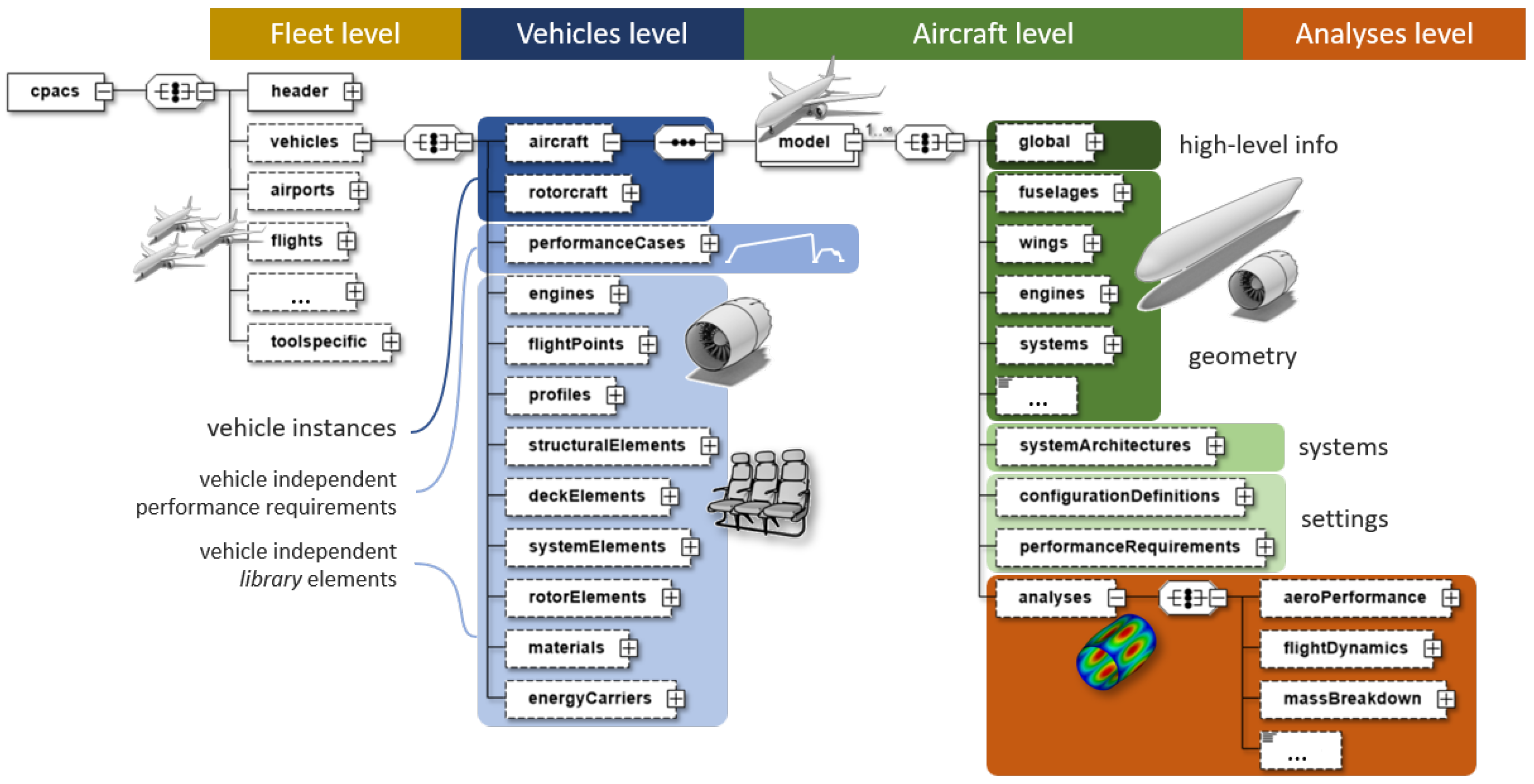
The data hierarchy implemented in XSD is shown in
Figure 2. It essentially follows a top-down structure of very explicit elements. This means that an entity (e.g., the wing of an aircraft) can be directly specified without necessarily providing a detailed description of it. The element name and its position in the hierarchical data model clearly indicate what the entity describes. This is important for the context of this paper, as not all details of a system are known at the beginning of a design process. It is also in contrast to other data models or Computer-Aided Design (CAD) environments, where the meaning of the parent entity must be derived from the combination of detailed information (e.g., the construction of a wing rib requires auxiliary lines and planes and Boolean operations on the wing skin).
Two data modeling concepts realized via XSD shall be highlighted to better understand the systems extension in CPACS: the first one is the concept of linking elements via unique identifiers (uID). Elements that have a uID attribute can be referenced elsewhere in the data hierarchy. This avoids a large part of the redundancy, as entities that are needed repeatedly (e.g., material data) need to be defined only once and can then be referenced at the appropriate places (e.g., ribs and frames of the wing structure). Another concept is that elements are initially described in a rather generic manner, but the explicit character can be specified via a type element, which specifies a restricted list of possible string elements (e.g., the systemType element in systemArchitecture can be assigned ata21 for Environmental Control, ata24 for Electrical Power, etc.).
With these concepts in mind,
Figure 2 shows four different levels in the CPACS data model. The fleet level defines everything which is required for system of systems analysis, and the vehicle level contains the actual instantiated vehicles (i.e.,
aircraft and
rotorcraft) together with the predefined “library” elements. At the aircraft level, specific aircraft architectures are described, consisting of high-level information, geometry, the actual system architecture described in this paper, as well as additional settings for configuration management and studies. Finally, the
analyses element stores the results of different analyses (e.g., structure, aerodynamics, loads) on the given aircraft.
Figure 2 not only shows the hierarchical relation between CPACS elements but also additional information on their occurrence: elements with solid borders are mandatory, while those with dashed borders are optional. The distinction between mandatory and optional elements offers as much flexibility to the user as possible but ensures that the logic of the schema is not violated; e.g., if specifying an
aircraft, a corresponding
model is required.
In summary, it can be concluded that the implementation of the CPACS data model with XSD according to the concepts described above allows a multi-fidelity representation of air transportation systems (i.e., different levels of detail can be defined and combined as required). Additionally, CPACS can be used to parameterize aeronautical systems from fleet to component level. This framework serves as a starting point for the extension of the system definition in CPACS, which is presented in detail in
Section 3.
2.2. Related System Representation
This section is dedicated to different examples of system representation in aviation and beyond, influencing the new schema definition. The examples highlight the differences between a specific system representation of aircraft systems and a generic system representation.
It is a well-established practice in aviation to distinguish the aircraft systems according to the Air Transport Association of America (ATA) Specification 100 [
18]. This specification subdivides the systems by functions and groups them into different, so-called ATA chapters. This unified referencing system provides a consistent framework for technical documents and maintenance manuals [
19]. These chapters reflect the commonalities of the different aircraft systems, which makes them applicable independently of the aircraft type. For example,
Table 1 provides the subsystems of ATA Chapter 24, the Electrical Power System. This breakdown shows the explicit character of the ATA chapter-referencing system.
In contrast to the ATA chapters, the following system representation is more generic: SysML is a widely used modeling language for systems engineering [
20]. Based on the Unified Modeling Language (UML), it has been developed to provide a standard modeling language for systems engineering. Its purpose is to “analyze, specify, design and verify complex systems” [
20]. Due to its generic character, SysML can be applied to a wide range of applications. The specification of system requirements, behavior, structure and parametric relationships are known as the four pillars of SysML. For the definition of systems in CPACS, only parts of SysML are related, such as the structure. For example, the hierarchy in SysML can be expressed by using
blocks to represent top-level systems, systems, subsystems, components or parts. Moreover,
blocks are a collection of parts and connections, which enable communication and interaction. Besides the hierarchy and connections, data, material or energy can cross the boundary of a
block at a
flowPort. These
flowPorts can be specified to indicate a direction and the allowed properties. This basic structure can be combined and enriched with, e.g., parametric relations, sequences or requirements. The universal formulation of SysML provides the user with a maximal freedom to specify the systems as required. It does not aim for a standardized language for a domain of application.
The third example might be interpreted as a compromise between specific and generic system definition: Strack et al. [
21] introduced a prototype data structure in CPACS for the preliminary sizing of hybrid propulsion systems in 2016. The proposed data structure aims for a generic definition and introduces the node
propulsionSystems. Each
propulsionSystem inherits its
components and their
connections. The
propulsionComponent is defined by several pieces of information such as its type, geometric shape and transformation. Additionally,
ports can be used to differentiate between various connection possibilities. Depending on the specified inputs and outputs (
IOCharacter), the component behavior can be stored in a
performanceMap. Following this logic, for a given set of inputs the respective output can be interpolated from the
performanceMap. An architecture is created within the
connections node, where two
uIDs of the
ports define a
connection. This data format is used in a distributed design environment, where different tools were integrated into a common workflow in the Remote Component Environment (RCE) [
22]. The proposed schema was not published in an official CPACS release, but the basic ideas are reflected within the actual CPACS system definition.
While
Section 2.1 shows that CPACS follows a top-down approach, the Aircraft Design Markup Language (ADML), developed at the Virginia Polytechnic Institute and State University, rather represents generic systems by describing its components on a detailed level using abstract mathematical models (i.e., following a bottom-up approach) [
23]. In this way, ADML primarily aims at modeling unconventional aircraft and aircraft systems. However, the bottom-up approach is often not compatible with typical aircraft design processes, where the level of detail is only reached gradually. It is unknown whether this is one reason why ADML has not found significant distribution.
3. Data Structure of the System Description in CPACS
Introducing a data standard for modeling aircraft systems in CPACS raises several challenges. On the one hand, the inherent complexity of such systems must be taken into account. On the other hand, the explicit nature of CPACS should be maintained (i.e., entities are explicitly named without the need to provide details). In addition, it must be considered that a heterogeneous group of stakeholders with different perspectives and needs would use this definition in the future. The following outlines a structure that attempts to meet these challenges.
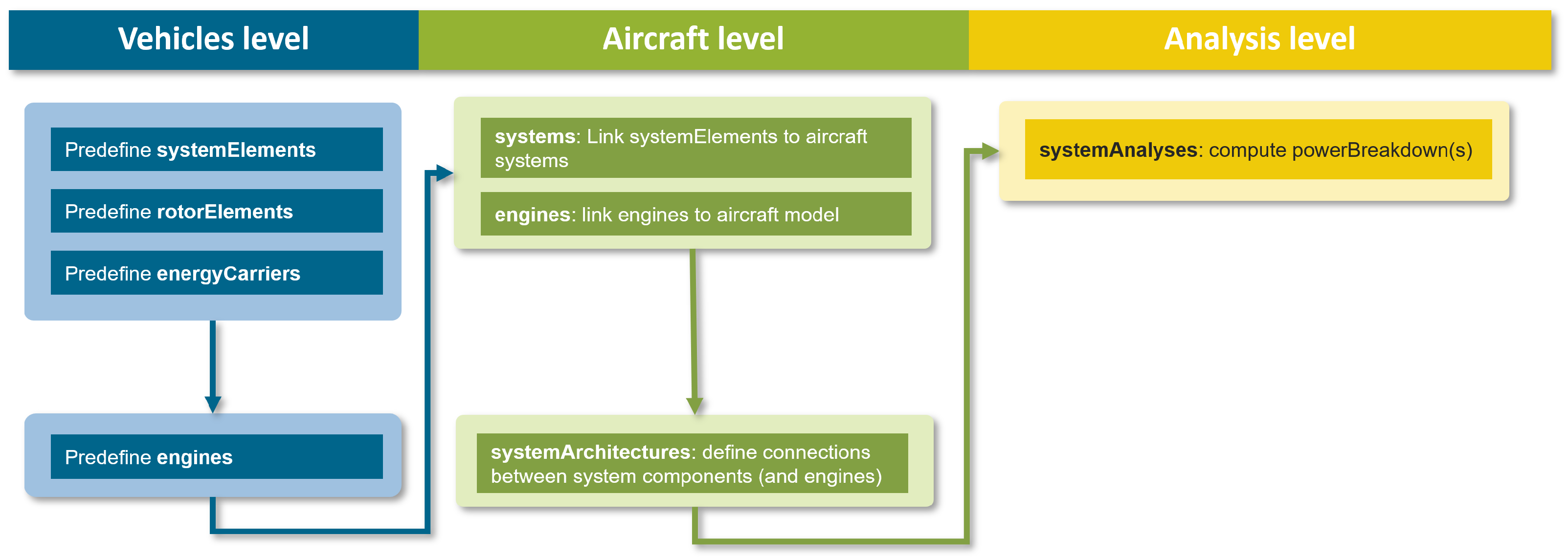
The actual system definition extends over three hierarchical levels in CPACS, as shown in
Figure 3. This comprises predefined aircraft-independent system components at the
vehicles level, the actual system definition at
aircraft level, and finally the corresponding system analysis at
analyses level. The aforementioned
fleet level remains unchanged by the introduction of the system definition. Recent CPACS schema developments and application cases with respect to the
fleet level can be obtained from Alder et al. [
24].
3.1. Vehicles Level
Section 2.1 introduced that recurring elements are usually predefined in CPACS, which can be thought of as “library” items. This is particularly relevant for aircraft systems, as many components (e.g., batteries, electric motors, etc.) need to be used repeatedly. The
vehicles element, which not only comprises the actual vehicles
aircraft and
rotorcraft but also the corresponding “library” elements, was therefore extended by
systemElements. The naming orientates on CPACS naming conventions (e.g., “structuralElements” or “deckElements” [
25] on the same hierarchy level) and achieves a semantic differentiation to the actual (instantiated) components at
aircraft level.
In the first release of the system definition in CPACS v3.5, only a small selection of explicit system elements was published to illustrate the principle of using predefinable elements. The genericComponents element is used to model additional components by a generic description in a schema-compliant way. The underlying CPACS development strategy is to identify generic elements that are frequently used in practical applications and to extend the schema by an explicit description of such.
Each element consists of a base type that represents geometry and mass information. This allows to either preselect a simple geometric shape (e.g., a cube), or link a CAD file (e.g., an Initial Graphics Exchange Standard (IGES) file) as genericGeometryComponent. This base type could be extended by component-specific data, such as performance maps, voltage, pressure or temperature levels, but also information about mean time between failures. The definition of explicit systemElements, as well as their specific parameters, will be part of CPACS updates since dedicated feedback from the component experts is required for the development process.
Furthermore, rotors were copied from the rotorcraft node (still available for backwards compatibility) to the vehicles level and consistently named rotorElements. This allows to explicitly model and link rotors in the aircraft or engine nodes, preventing the misuse of rotorcraft for modeling fixed-wing aircraft propellers and reducing the size of data sets through the reuse of predefined rotors.
A fundamental question during the development of this CPACS extension was whether future system architectures (e.g., hybrid-electric aircraft) could be described using the classic engine. It was decided to retain the engine node to represent conventional turbofan and turboprop engines. Additional components such as electric motors can be defined via systemElements. It is then up to the user to decide whether the combination of electricMotor and rotor (e.g., for distributed propulsion) is interpreted as an engine or not.
Finally, a related CPACS modification concerns the energyCarriers at the vehicles level. With the increased interest in investigating different energy carriers for the use in an aircraft, the former fuels node has been extended and grouped under energyCarriers. This mainly serves two objectives: different energy carriers can be explicitly linked to the aircraft concept and the economical and ecological assessment can refer to a unified data source. To enable automatic data processing, the type of fuel (e.g., kerosene, hydrogen, ammonia) has to be chosen from a given list of keywords. Additionally, emission indices (h2oEmissionIndex, co2EmissionIndex and n2EmissionIndex) can be specified, which support the calculations for the climate assessment. For the economical assessment, an energySpecificCost node is added. In contrast to the chemical energy carrier fuel, the final implementation of electrical energy carriers have not been worked out in detail at the release date of CPACS v3.5. This is planned for the next CPACS release.
3.2. Aircraft Level
The following discussions in this paper will make use of so-called XSD diagrams to explain the systems extension in more detail. Additional information that can be derived from XSD diagrams is the sequence of the elements: If there is a symbol with three dots arranged on top of each other, the order of the following elements is arbitrary (see
Figure 4a between
genericSystem and
name); for the symbol with three dots arranged in a row, the order of the following elements is fixed (see
Figure 4a between
component and
name). The symbol indicating a switch states that the user must choose from one of the following elements (see
Figure 4a between
systemElementUID and
rotorElementUID).
There are two complementary system descriptions at the aircraft level. First, there is a physical/geometric definition of all system components in systems/genericSystems. Second, connections between such components can be described under systemArchitectures. Both views are explained in more detail below.
The
genericSystems (implemented as
genericSystemsType, see
Figure 4a) lists all physical components in the aircraft in terms of its geometry, mass and location. This means that each system and each component physically exists in the aircraft as many times as it is referenced and in
genericSystems. For example, even if a battery is used for different system architectures, it must not appear redundantly in the
genericSystems node, which is important for weight and balance or life cycle analysis. Therefore, the definition is still generic at this point. Linking
systemElements via their
uID yields the explicit character of CPACS again, because following the
uID link returns a predefined explicit
systemElement. The same holds for the
rotorElements, which should be referenced as system component if they cannot be classified as
engine. The
parentUID node specifies the parent coordinate system. If it is not specified, the
transformation refers to the global aircraft coordinate system. Often, however, this node refers to the
fuselage or
wing in which the component is installed.
A second aspect is important in this context. In a genericSystem, the transformation is intentionally optional, but if specified, it must contain values. This is necessary to uniquely list all the physical elements that will be used in the later system architecture, but avoid misinterpretation if the location is not yet known. However, from the perspective of a system architect, not every component can be assigned a position during the initial system design. This can be emphasized by not specifying the transformation element at all and thus preventing it from being considered for weight and balance analysis (e.g., an empty transformation element could be misinterpreted as implicitly located at the coordinate center).
While
genericSystems lists all physical components,
systemArchitectures provides information about the connections between components and their interfaces to other systems. Implemented as
systemArchitecturesType, the corresponding elements are shown in
Figure 4b. In accordance with the CPACS top-down approach, the system architecture can be specified by just providing a
systemType keyword. For this, a list of predefined string elements is available to enable automated processing when writing and reading the data: either a predefined ATA chapter (e.g.,
ata21) can be selected or the keyword
generic can be used. Via
controlDevices, the system
state can be assigned to a
controlParameter as active or inactive (e.g.,
1 and
0, respectively). This abstract
controlParameter can be used to specify different operating modes in CPACS. Finally, the actual
connections of the system are defined. Each connection consists of a
source and a
target. Here, the previously defined components and sub-components can be referenced via
uID attributes. Alternatively, an
externalElement (currently implemented is
ambient and
passengers) or
ataChapter can be selected from a given list of keywords, or another
systemArchitecture can be referenced via its
uID.
3.3. Analysis Level
One important feature of the introduced CPACS system definition is the possibility to store energy or mass flows, which are exchanged by components or systems. This expands the view of the aircraft as a combination of numerous energy systems. Therefore,
powerBreakdowns are introduced in analogy to the existing
massBreakdown at the
analyses level.
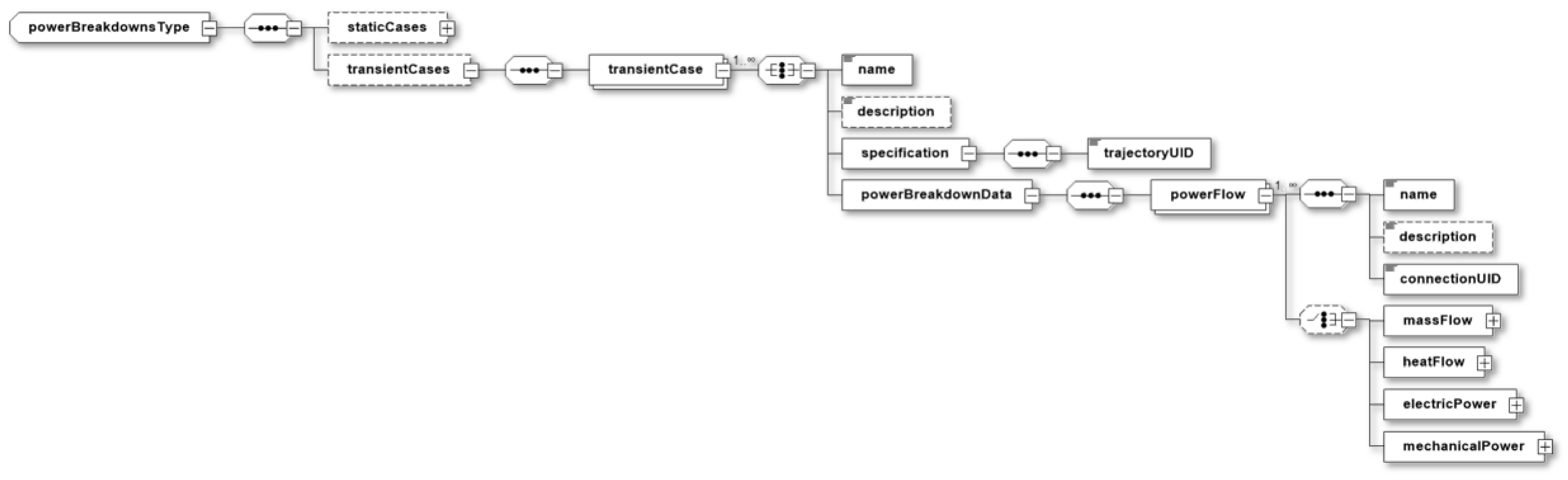
Figure 5 illustrates the new
powerBreakdownsType. For the exchange of energy and mass flows a specific “case” needs to be defined. Depending on the analysis, two types can be differentiated:
staticCases and
transientCases. Each analysis “case” is embedded in boundary conditions and, therefore, requires a
specification. The definition of the
specification differs depending on the choice of
staticCases or
transientCases. For
staticCases, the boundary and environmental conditions can be given in two ways and are implemented as a choice element. The first possibility is to specify all required information directly, such as the
altitude, the speed (choice between
machNumber,
calibratedAirSpeed or
trueAirSpeed) and the
environment with the corresponding
atmosphericModel such as the International Standard Atmosphere (ISA). The other option is to link the
specification with a global
flightPointUID, which is stored in
vehicles/flightPoints and entails the same information. Optionally, the
specification can be linked to a
configuration, where a condition of the aircraft vehicle itself can be specified. For the
transientCase, the
specification needs to be linked to an existing trajectory by a
trajectoryUID.
Once defined, the specification, the energy and mass flows are listed in the powerBreakdownData in an unsorted manner. In order to stress that energy or mass cross the boundaries of components, these flows are assigned with a direction by referring to their source and target. Making use of the functional relationships between components already specified in systemArchitectures, the powerFlow is declared for a connection and referred to it by uID. This reference links the energy and mass flows on the analysis level to the instantiated system components on the aircraft level. That implies, that powerBreakdownData can only be stored for an already defined system architecture.
Four choice elements are used to categorize the powerFlow. The structure of the powerFlow nodes is always the same: A flow or power value has to be given (a scalar for staticCases and a vector for transientCases), which serves as the magnitude. Additional information of the flow is optional and specific to the category of the powerFlow. The first category is the massFlow, which can be differentiated between singlePhaseMassFlow and multiPhaseMassFlow. By adding this choice element, the thermodynamic state can be fully defined with the pressure and temperature, which improves the human readability. Besides the thermodynamic state, the massComposition can be given as list of species, which consist of a type, such as for example air, and their share. It was decided to use the massFlow as unambiguous definition for several applications: for example, bleed air with high pressure and temperature could be specified with it, as well as kerosene fuel, where the chemical potential is rather of interest. Another category is the heatFlow, which is defined by the heatFlowValue and optionally specified by the sourceTemperature and sinkTemperature. The electricPower is the third category of the powerFlow. As an optional choice, the current can be selected as directCurrent or alternatingCurrent with the effectiveVoltage, frequency and phase. The mechanicalPower is the last choice option of the powerFlow. Besides the mechanicalPowerValue, the torque or force can optionally be specified to consider rotating or linear power transmission, respectively.
4. Application Examples
The incorporation of an OBS architecture description format into the CPACS data schema enables more integrated sizing and analysis approaches between the overall aircraft design (OAD), including engine design, and the overall on-board systems design (OSD) disciplines. Since the chosen OBS technologies and overall OBS architecture heavily influence the OAD, e.g., by means of mass, center of gravity distribution, available installation space, and power demand, several iteration loops are required in the scope of aircraft conceptual design. Until now, the OSD community was obliged to establish its own exchange format in order to facilitate the availability of sizing and analysis data at the component and architectural levels to OAD. This gap is closed by the introduction of CPACS v3.5 described above.
The advantages of incorporating the OSD data into the CPACS data schema are illustrated in the following section. As first example, the schema is used to describe a conventional OBS architecture of a short–medium range (SMR) concept aircraft. Second, the OBS architecture of an all-electric, fuel cell-powered regional concept aircraft is exemplarily shown.
4.1. Conventional On-Board Systems
The SMR concept aircraft DLR-F25 powered by sustainable aviation fuel (SAF) serves as the first example in terms of describing a conventional OBS architecture by using the CPACS v3.5 data schema. The aircraft and its OBS architecture is described in detail by Wöhler et al. [
26]. It features a design range of
, a cruise Mach number of
and a max. operating altitude of 40,000
, and it accommodates 239 passengers.
For the conceptual design of the DLR-F25’s OBS architecture, the OSD framework developed at the Institute of Aircraft Systems Engineering at Hamburg University of Technology (TUHH-FST) is employed [
27,
28,
29,
30,
31]. Featuring a direct interface to CPACS, the OSD framework comprises a model-based system engineering-driven approach for architecture definition, topology generation (i.e., positioning of the system components and connections), and system preliminary sizing, stating component-characteristic design parameters, component masses, the center of gravity distribution, and power demand.
In general, the OBS architecture of the DLR-F25 follows a more-electric approach, incorporating technology that is anticipated to be available by 2035. This is particularly noticeable in terms of the primary flight control system (FCS) and the electric power supply system (EPSS). Beside solely including hydraulic actuators, the FCS additionally comprises electro-hydrostatic and electro-mechanic actuators. The EPSS follows a distributed architecture layout [
27]. In this configuration, the variable frequency generators (VFG) at the engines provide electric power to the two primary electric power distribution centers (PEPDCs) and two secondary electric power distribution centers (SEPDCs). From there, electric power is distributed throughout the aircraft by means of eight secondary power distribution boxes (SPDBs), to which the electronic devices are connected. The environmental control system (ECS) and ice protection system (IPS) are powered pneumatically using engine bleed air. The remaining systems are of a conventional nature, incorporating state-of-the-art technology.
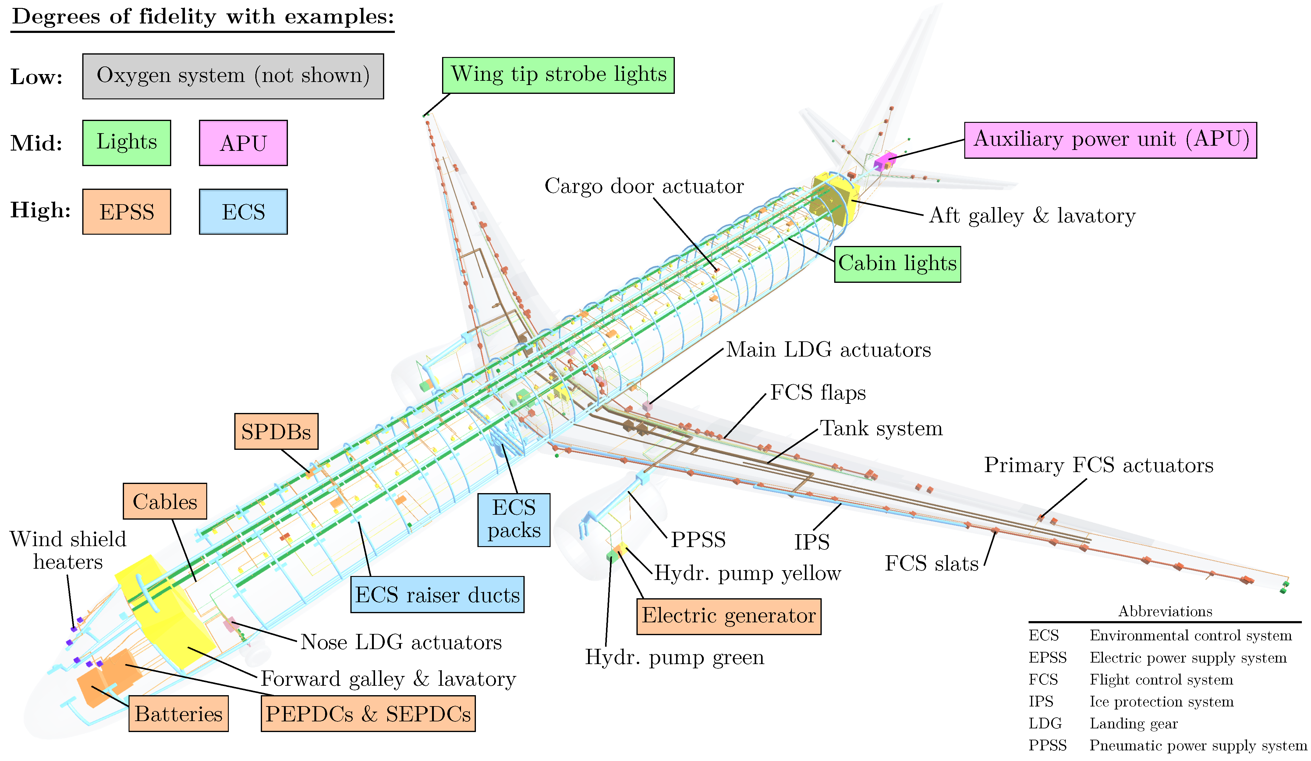
The DLR-F25’s OBS architecture is depicted in
Figure 6. For the sake of clarity, only selected system components are labeled. The illustration is intended to show, by way of example, that there are different degrees of fidelity relevant in the context of OSD sizing:
Low fidelity: data at system level;
Mid-fidelity: data at component level;
High fidelity: data at component and connection levels.
These degrees of fidelity can be mapped accordingly in CPACS v3.5. For example, the emergency oxygen system is of low fidelity, as the estimation of mass and center of gravity at system level is sufficient in the scope of OBS conceptual design. Additionally, as this particular system does not comprise a power supply network of any type and can be neglected regarding power consumption, it is unnecessary to conduct a more detailed examination at the component level. In the CPACS data schema, the oxygen system is defined as a genericSystem but does not inherit any systemElements.
The lighting system is of mid-fidelity and necessitates the mapping of its components in three-dimensional space. This is due to the fact that the system is distributed throughout the aircraft’s geometry, posing implications at the OAD level concerning mass and center of gravity. Moreover, mid-fidelity systems are intertwined with other systems. In this example, the lighting system poses a non-neglectable electric consumption and is connected to the EPSS. In CPACS, in addition to the previously described oxygen system example, each aircraft light is defined as a
genericComponent under the
systemElements node. Each
systemElementUID is referenced by the
components of the
genericSystem “lights” (cf.
Figure 4).
Lastly, the EPSS is of high fidelity and comprises multiple components and connections, i.e., cables, distributed throughout the aircraft. In this case, the degree of modeling is selected with greater precision in order to map the mass influence of the numerous cables in particular. Furthermore, the EPSS is physically connected to power-relevant on-board consumers in order to model the total OBS power requirement at the generator. The
systemsArchitectures node in CPACS is used to describe the EPSS. In addition to referencing the
systemElementUIDs of the relevant
genericComponents to map the EPSS components, the complete EPSS architecture is described by defining the appropriate
connections between the
source and
target componentUIDs (cf.
Figure 4).
The OBS components and connection data stored within the CPACS schema facilitate the generation of diverse levels of system visual representation.
4.1.1. Graph-Based Representation
The graph-based representation offers the system engineer a straightforward yet effective method for visually verifying the logical connection of components within a given system or between disparate systems, without initially providing superfluous information such as spatial position or more detailed component design parameters, such as mass or installation space.
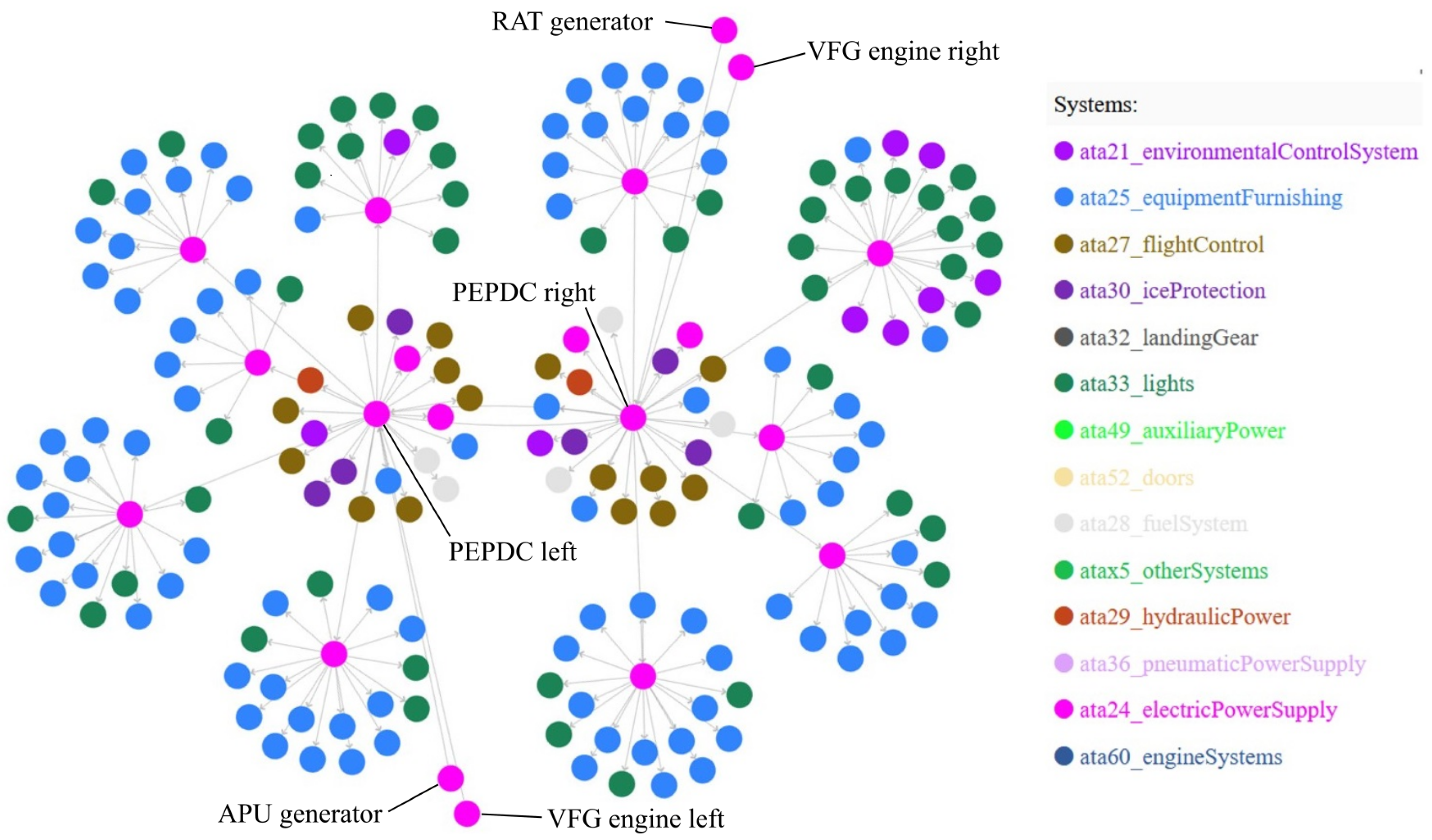
Figure 7 exemplarily shows the logical architecture of the EPSS, including its electric consumers, in terms of a directed graph, visualized with Cytoscape (
https://cytoscape.org/) [
32]. Each of the two engines provides mechanical power to the VFGs through the accessory gear box. The VFG converts the mechanical power to electrical power, which is transported to the two PEPDCs. For emergency operation, a ram air turbine (RAT) is connected to the right PEPDC. The electric generator of the auxiliary power unit (APU) connects to the left PEPDC. The main electric consumers, such as the ECS packs, galleys, flight control actuators, fuel pumps and electric hydraulic pumps are connected to the PEPDCs. Smaller electric consumers, e.g., aircraft and cabin lights, as well as the passenger service units (PSU) included in “ata25_equipmentFurnishing”, draw their electric power from the SEPDCs and SPDBs, which are in turn connected to the PEPDCs. Moreover, the PEPDCs are interconnected to ensure the flexible redistribution of electrical power in the event of an emergency.
4.1.2. Geometric Representation
In addition to the logical graph-based representation, with the geometric representation, the spatial plotting of the OBS components and connections within the aircraft geometry is addressed. As previously introduced,
Figure 6 depicts the 3D-visualization of both the aircraft geometry and system geometry information as integral parts of the DLR-F25 CPACS data set. The geometric representation allows the system engineer to conduct a visual verification of the OBS’s location and integration within the aircraft geometry. Moreover, the enriched geometric model enables further analyses and inspections of the installation space.
4.1.3. Power-Specific Representation
The availability of
powerBreakdowns in the CPACS v3.5 schema allows for a visual power-specific representation of the OBS architecture, parts of the architecture or individual components. To this end,
staticCases and
transientCases can be included in the representation, aiming at giving the system engineer an overview of the power flows and losses occurring within the considered system or between systems. A Sankey diagram is a suitable method of representation and used within this study for visualization [
33].
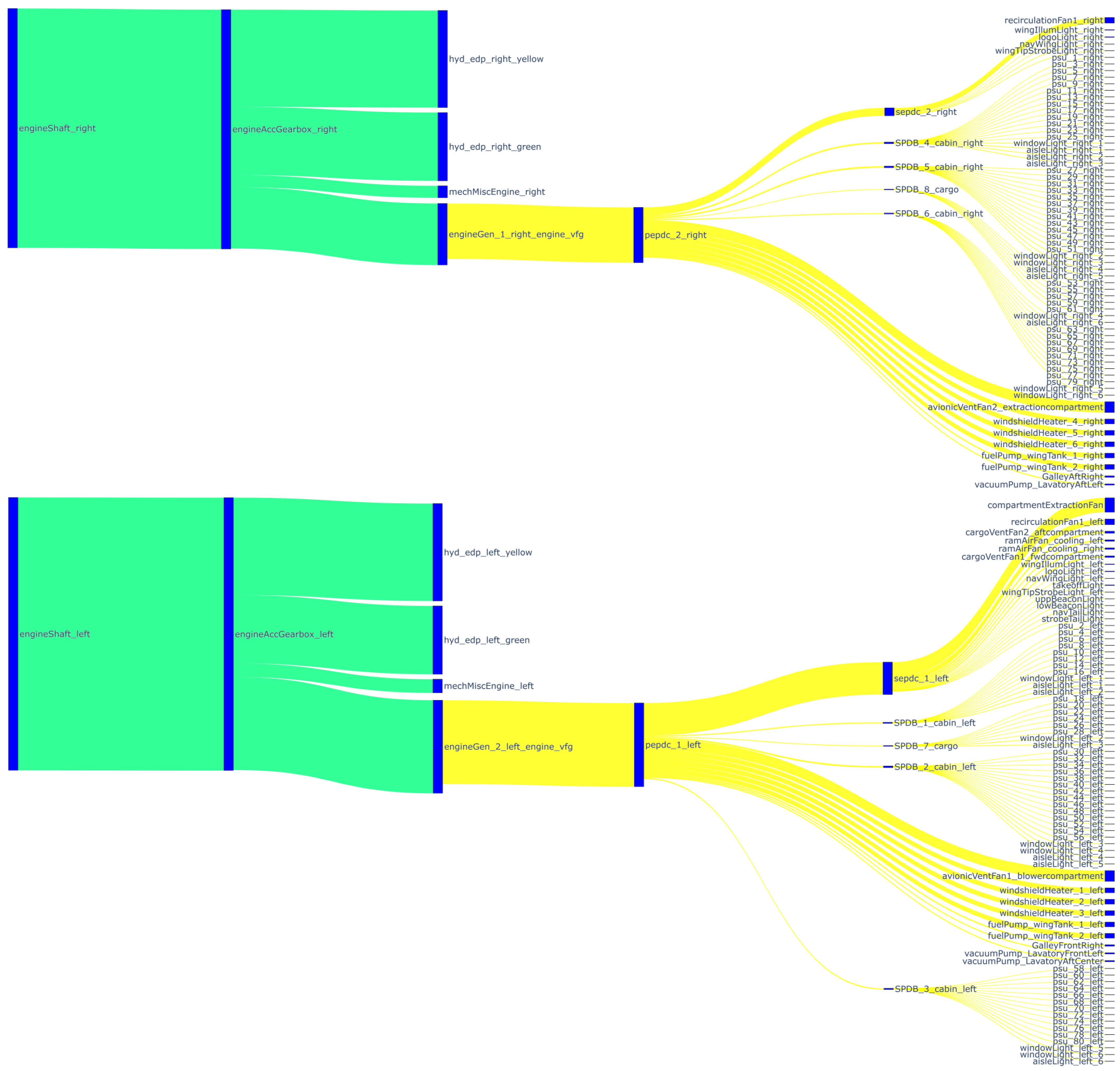
As such,
Figure 8 exemplarily depicts the power flow within the EPSS for the
staticCase “top of climb”. The engines provide mechanical power (highlighted green in
Figure 8) to the accessory gear boxes, one at each engine. From there, the power is split between the hydraulic pumps, the VFGs, and the engine accessories, considering small losses. For the sake of clarity, the respective power breakdown of the hydraulic system is not further elaborated. The electrical power (highlighted yellow in
Figure 8) is transferred from the VFG to the PEPDC, considering losses in the electric components and cables. The PEPDC is responsible for the distribution of the available electrical power, ensuring that all loads on the right-hand side of
Figure 8 are supplied. It should be noted that the power breakdown of the left and right wing sides is asymmetrical for this
staticCase of the
powerBreakdown.
4.2. Fuel Cell Propulsion
The hydrogen-powered concept aircraft ESBEF-CP1 (German acronym for “Development of Systems and Components for Electrified Flight” Concept Plane 1) is used as another example to illustrate the CPACS v3.5 data schema in order to store OBS architecture parameters. As a regional concept aircraft, the ESBEF-CP1 has been developed in scope of the DLR EXACT project and is derived from an ATR 72-like aircraft model [
34].
Serving as a technology demonstrator to analyze technologies for a hydrogen aircraft, the ESBEF-CP1 has ten propulsion units (pods), each containing hybrid fuel cell systems and peripheral systems, such as the cooling system, hydrogen supply, air supply, and an electric power management unit (PMU). In the aft of the fuselage, two cryogenic hydrogen tanks are positioned. Further design parameters are, among others, the range of the design mission, which is
, and the cabin seating capacity for 70 passengers [
34].
Since it is described in the section above that conventional OBS can be stored in CPACS v3.5, this example illustrates that more disruptive systems, such as an electric power train, can be stored in the CPACS v3.5 data schema as well [
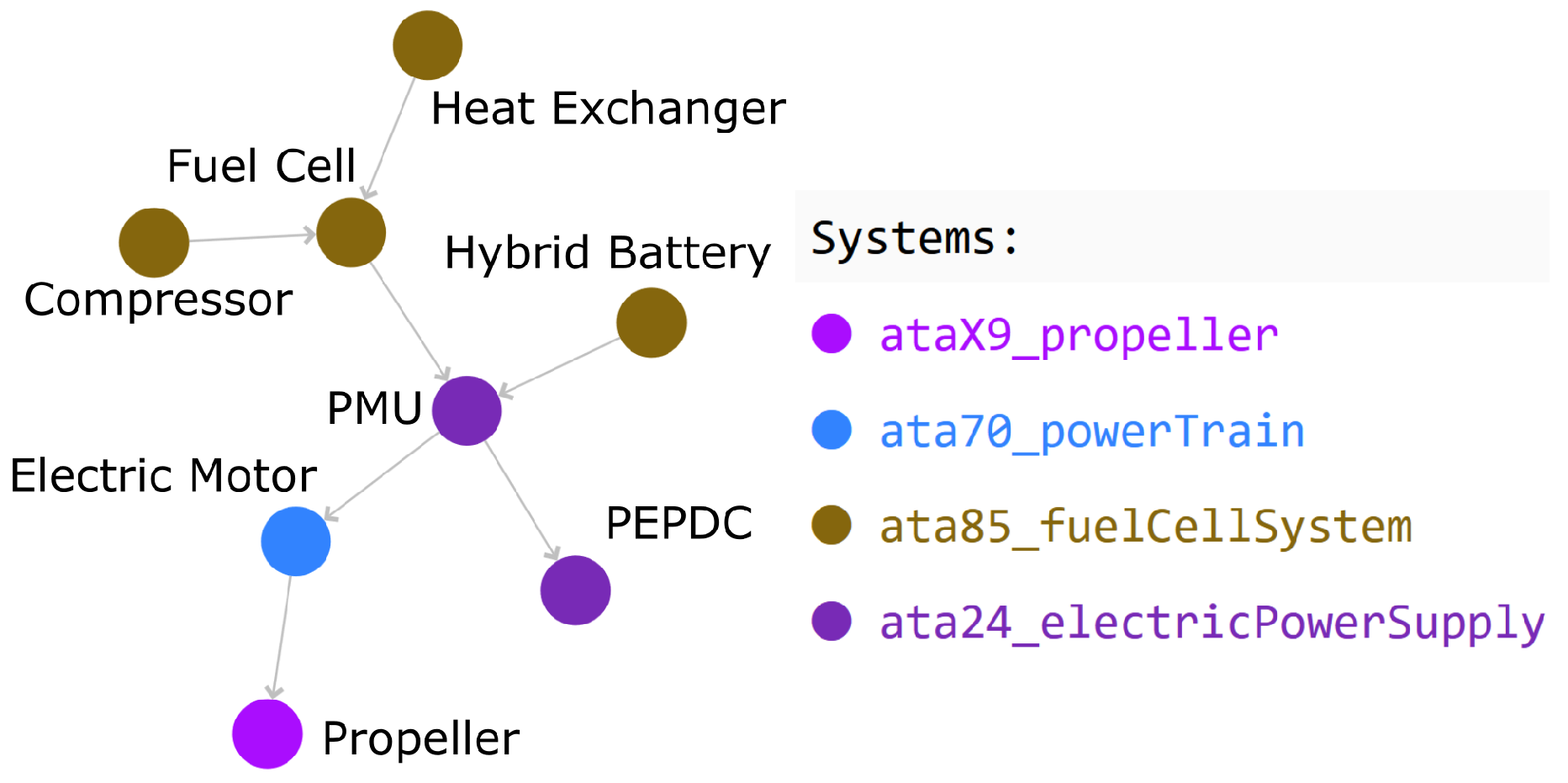
35]. To this end, the topology of a simplified system architecture of the systems in one pod of the ESBEF-CP1 is shown in
Figure 9. This includes the fuel cell and a battery for hybridization as power sources. Furthermore, a heat exchanger representing the cooling system and a compressor representing the air supply system for the fuel cell is displayed. The power management unit distributes the electric power from the fuel cell and the battery to the EPSS and to the electric motor, representing the electric power train, which consists of a motor controller, an electric motor, and a gearbox.
4.2.1. Graph-Based Representation
Figure 10 shows the graph-based representation of the ESBEF-CP1 pod, visualizing the components displayed in
Figure 9 and their logical connections as intended. The battery and the fuel cell are connected to the PMU, while the PMU is connected to the PEPDC as part of the EPSS and the electric motor. The electric motor is connected to the propeller. Also, the heat exchanger and the compressor are connected to the fuel cell as part of the required peripheral systems.
4.2.2. Power-Specific Representation
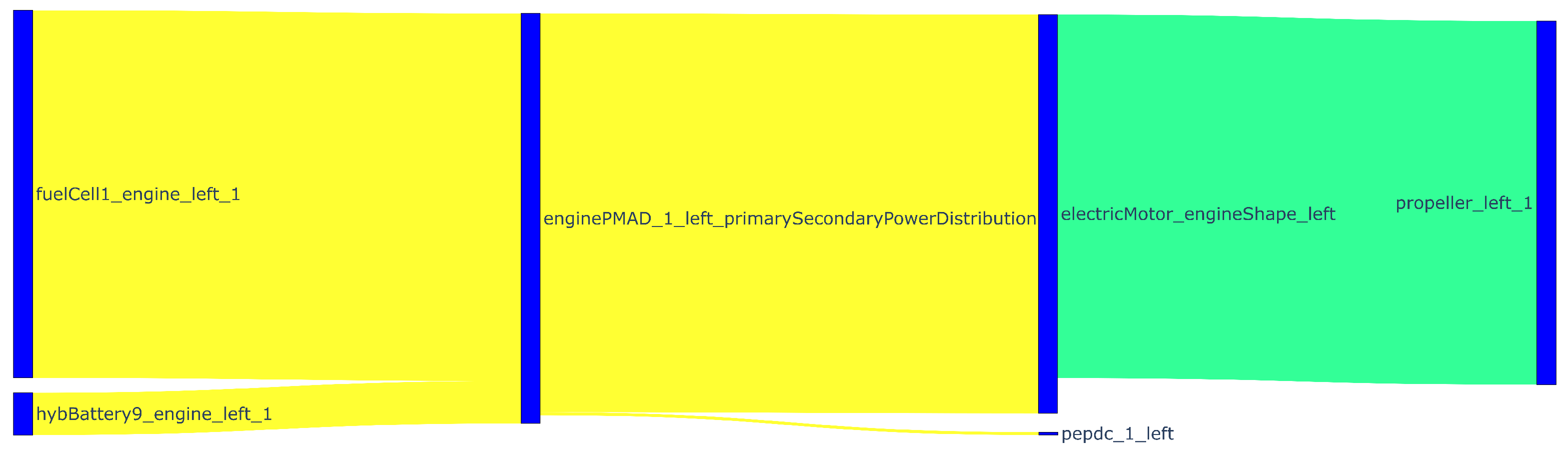
The power-specific representation of the ESBEF-CP1 Pod is visualized in
Figure 11 and shows the power flow during take-off. In this flight phase, both the fuel cell and the battery provide power due to the increased power demand [
35]. Furthermore, the share of electric power between the power train and the EPSS is visualized, illustrating the significant higher power demand for the power train compared to the EPSS. Lastly, the change of power type from electric to mechanical power at the electric motor can be seen, as well as the power loss at the electric motor due to its efficiency.
5. Conclusions and Outlook
In this paper, the introduction of a system definition for the CPACS data schema is described. Aiming for a standardized interface for the improved integration of propulsion and on-board systems into the aircraft design process, several extensions are made to the schema. The system definition is implemented within three hierarchical levels. At the vehicles level, aircraft-independent system components are predefined serving as “library” items. These system components can be linked at the aircraft level, where two complementary system descriptions are defined: a physical/geometric definition in systems/genericSystems and a logical/functional definition in systemArchitectures, where the connections of the instantiated components are described. Based on these connections, energy or mass flows can be stored at the analyses level in powerBreakdowns. This provides the user the opportunity to exchange analysis results of the on-board systems for a specific architecture at a specific operation case (e.g., staticCase or transientCase).
The applicability of the system definition is demonstrated by two examples. A detailed description of a conventional on-board system for a SMR aircraft concept is presented. It is found that all relevant information can be stored in the data schema for this example of higher fidelity. The second example showcases an electrical propulsion system at a lower level of fidelity, which proves the flexibility of the schema.
With the system definition being part of the CPACS v3.5 release, the application phase already started. Constantly learning through user experience, this schema will be further improved and extended where necessary. For example, more predefined
systemElements might be added to cover the wide range of applications. Their specific parameterization beyond
mass and
geometry will be discussed with experts from the respective domains, following the CPACS development strategy [
10]. Also, the treatment of the difference between the chemical potential of fuel and electrical potential of charged batteries under the
energyCarrier node is not yet finally decided. With some changes to the previous schema, such as allowing the shift of
rotorElements in the
aircraft level, post-processing tools such as TiGL [
17] need to be adapted. The increased complexity of the schema by linking elements across multiple levels of hierarchy hinders human readability. This trade-off between schema flexibility and simplicity requires good visualization for understanding and debugging. Therefore, library functions for evaluating the complex
uID dependencies and filtering would support the accessibility of CPACS. Moreover, the topology of the aircraft energy distribution networks needs to be explicitly added to the schema. Therefore, a specific extension for ducts, pipes and cables is planned and will be introduced in a future CPACS release.


 ,
, 


