Article

Dynamics Modeling and Analysis of a Vertical Landing Mechanism for Reusable Launch Vehicle

1
School of Mechanical Engineering, University of Science and Technology Beijing, Beijing 100083, China
2
Beijing Interstellar Glory Space Technology Co., Ltd., Beijing 100176, China
*
Author to whom correspondence should be addressed.
Aerospace 2025, 12(4), 280; https://doi.org/10.3390/aerospace12040280
Submission received: 15 February 2025 / Revised: 25 March 2025 / Accepted: 25 March 2025 / Published: 27 March 2025
(This article belongs to the Section Astronautics & Space Science)

Abstract

:
In this work, a vertical landing mechanism of a reusable launch vehicle (RLV) is investigated using a flexible–rigid coupled dynamics model. The presented model takes into account the four-legged landing mechanism and the main body cabin. Flexibilities of the main components in the vertical landing mechanism are considered. The hydro-pneumatic spring force and thrust aftereffect caused by the sequential deactivation of the engine are introduced separately. Several simulation cases are selected to analyze the loads acting on the landing mechanism and the dynamics behavior of the whole RLV system. Simulation results show that considering flexibility in the landing mechanism is critical for dynamics analysis under various initial conditions. The adopted RLV design is capable of achieving stable landings under specified initial velocity and attitude conditions, demonstrating its feasibility for engineering applications. Moreover, the hydro-pneumatic spring plays a crucial role in absorbing the impact of the initial landing leg, ensuring a smoother landing experience and minimizing potential damage to the vehicle.

1. Introduction

In recent years, reusable launch vehicles (RLVs) have attracted significant attention in the field of space flight and exploration. Notable contributions in areas such as control algorithms, analytical models, numerical simulations, and hardware tests have been made. As one of the most promising developments, vertical landing technology offers advantages such as a low cost, high launch efficiency, and small landing area requirements. Therefore, the design and analysis of vertical landing mechanisms are also receiving increasing attention. The landing mechanism is a vital component of the vertical landing RLVs, which is responsible for energy dissipation during the touchdown and finally facilitating a stable landing and supporting the RLV main body cabin.
The dynamic performance of the landing mechanism has a direct impact on the state and subsequent service life of the RLV. Therefore, it is necessary to analyze the dynamic performance of the vertical landing mechanism. During the touchdown phase, the rocket engine and attitude control system are deactivated. The RLV lands under the gravity force and inertia. Due to the fact that the initial attitude, velocity, and angular velocity of the RLV are uncertain and affected by factors such as lateral wind loading and thrust aftereffect, the vertical landing mechanism faces numerous challenges in the landing and touchdown phases.
To address these challenges, multiple designs of landing mechanisms have been developed to mitigate the landing impact and accommodate various initial conditions. However, conducting a large number of physical tests is highly impractical due to the complexity and risks associated with the contact and impact [1]. As a result, numerical simulation has emerged as an effective and economical approach to predict, evaluate, and optimize the performance of landing mechanisms. For instance, DLR [2] developed the DLR FlexibleBodies library to support the object-oriented and mathematically efficient modeling of flexible bodies for the simulation of arbitrary physical systems.
In recent years, a substantial amount of research has been conducted by scholars in the field of designing and analyzing vertical landing mechanisms. Recent studies have focused on dynamics modeling and preliminary design optimization for RLVs [3], with some research exploring the spring and damping characteristics of landing mechanisms in RLVs [4]. The passive hydro-pneumatic spring is the optimal choice for achieving excellent buffering performance under very large impact loads. The stiffness of the spring is low at little displacement during landing and increases at higher displacement of the absorber. The highest stiffness of the absorber reached at the maximum spring compression guarantees that the launcher will not sink in at parking and finally touches the ground. A notable case is the development of a model for a liquid spring damper under impact conditions during vertical soft landing by Yue et al. [5,6], which was experimentally validated to be effective in analyzing the dynamics of an RLV. Yue et al. [7] also established a new nonlinear lumped parameter hydraulic model of a liquid spring damper, which was validated by a simplified single-leg impact test. Based on the same design, network-based modeling is presented [8] and analyzed for the nonlinear liquid spring damper of a vertical landing mechanism. Witte et al. [9] presented a high-fidelity numerical simulation to analyze the lander touchdown dynamics in the presence of planetary terrain features. Yu et al. [10] proposed a novel legged deployable landing mechanism for RLV, which has proved to be a potential alternative for developing future landing mechanisms after being systematically evaluated and improved. Thies [4] developed a rigid model of a legged landing mechanism with nonlinear spring characteristics, which can be used to analyze different complex landing scenarios for a stable landing to reach the parking position. In addition, the author mentioned that the current mathematical model shall be extended to a coupled simulation between rigid and flexible, which is important for the analysis of the landing dynamics.
However, despite the progress in impact and contact dynamics modeling, little attention has been paid to the flexibility of the landing mechanism. Most of them are typically modeled as rigid bodies [11,12] or simplified single flexible beams [7,13,14]. There is very limited literature focusing on flexibilities of the landing mechanism, and simulation results of the existing research show that structure flexibilities of the struts influence the accelerations and forces significantly [15]. During the touchdown of a landing mechanism, flexibilities of the struts and nonlinear stiffness–damping of the hydro-pneumatic springs will significantly influence the dynamics behaviors of the whole RLV. Thus, a flexible–rigid coupled model with nonlinear spring damping–stiffness enables a better assessment of actual landing performance, which is essential for reusability evaluation. Moreover, in the initial touchdown stage, the engine will be shut down. It was observed that the engine thrust does not disappear instantaneously upon the engine shutdown but exhibits an aftereffect by a stepwise decline in about 2 s. This aftereffect impacts both the acceleration and the joint reaction forces of the RLV main body cabin. Nevertheless, few studies have focused on the aftereffect during touchdown, in particular, the aftereffect acting on a flexible landing mechanism. In order to achieve reliable simulation results for some engineering designs, it is necessary to establish a flexible dynamics model with the nonlinear hydro-pneumatic springs and the stepwise thrust after-effect.
In this paper, a flexible–rigid coupled dynamics model is presented to simulate the landing mechanism of an RLV. The landing mechanism is thoroughly described, and the system load under various working conditions is analyzed, serving as a theoretical foundation and reference for practical application. The remainder of this paper is organized as follows. The landing mechanism is introduced in Section 2, including the constraints and action forces analysis of one leg in the landing mechanism. The dynamics modeling is established in Section 3, encompassing kinematics description, constraint equations, and external forces. Section 4 presents simulation cases in detail, while Section 5 displays and discusses the simulation results. Section 6 concludes this paper and outlines future work directions.

2. Landing Mechanisms

In this section, the landing mechanism studied in this work is introduced in detail, including the overview of the legged design, the connections, and the interactions of different parts.

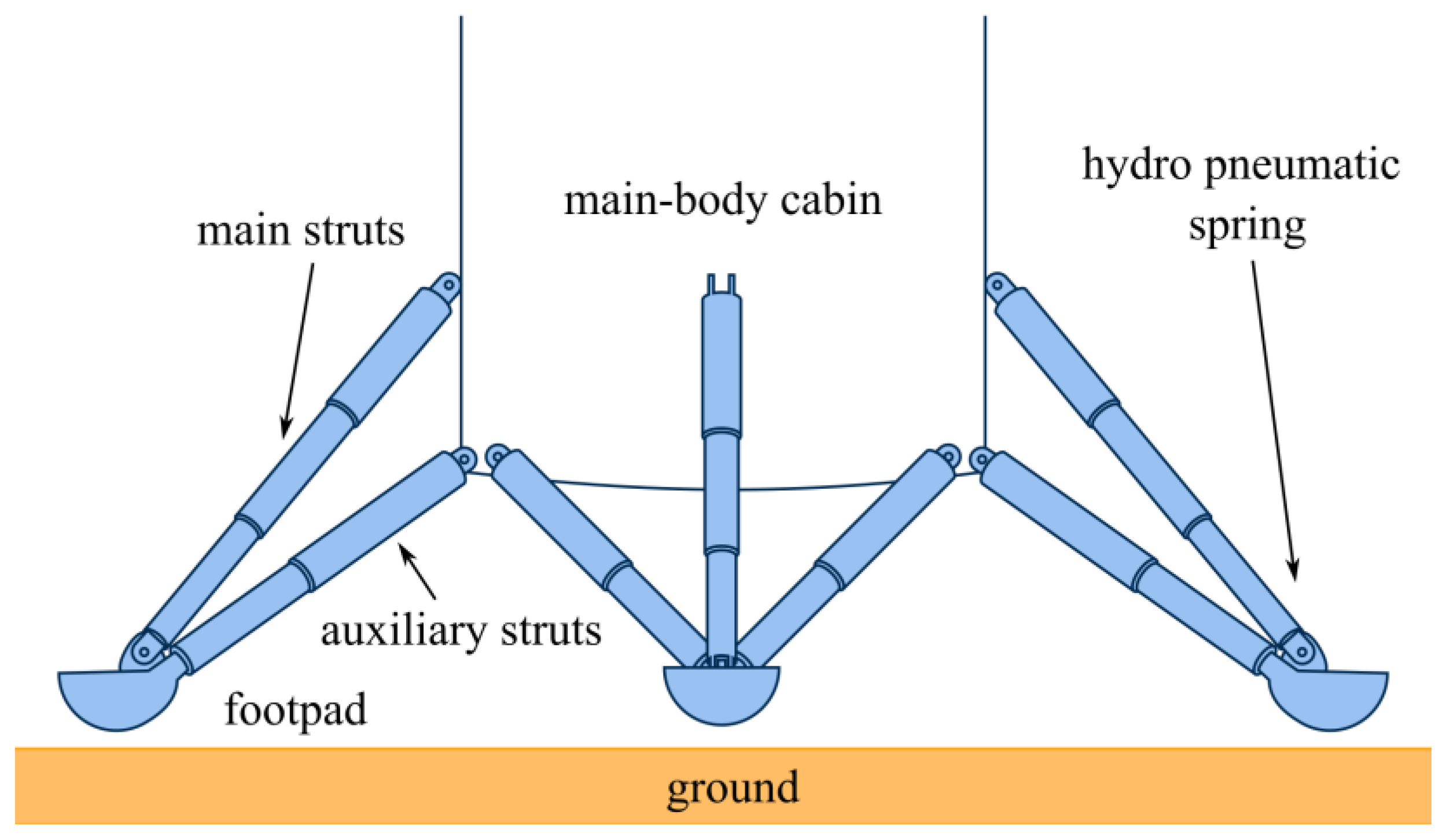
2.1. Overview of the System

The landing process can be divided into three phases: leg deployment, controlled descent, and touchdown. The thrust vector and throttling control are all active during the deployment and the controlled descent phases, which ensure a stable landing initial velocity and attitude. When the touchpad makes contact with the ground, the thrusts and attitude controller will be shut down and the RLV lands under the action of gravity and the initial vertical velocity. Therefore, during the touchdown phase, a stable landing mainly relies on the passive effect of the landing mechanism.
The landing mechanism of the system is depicted in Figure 1. There are four legs mounted on the main body cabin of the RLV. The four-legged landing mechanism has been demonstrated as the most promising design [4], and has been widely adopted in various studies [16]. The landing legs are folded and stowed in the main body cabin before landing to reduce aerodynamic drag and protect the struts during launch [17]. The landing legs need to be fully deployed to enable a safe landing and further reuse of the RLV. During that phase, the deployment system has to overcome harsh and challenging environmental conditions. Then, after the legs have been deployed as in Figure 1, the landing comes into the touchdown phase.
Each landing leg comprises one main strut, two auxiliary struts, and a footpad. One end of the main strut is connected to the main body cabin, and the other end is connected to the top end of the hydro-pneumatic spring, which is mounted at the lower end of the main strut to mitigate the landing impact energy. The hydro-pneumatic spring exhibits passive nonlinear spring-damping characteristics due to its compressible fluid design. The nonlinear characteristics provide variable stiffness at different compressions of the spring, which guarantees that the RLV will not sink in during parking [4].

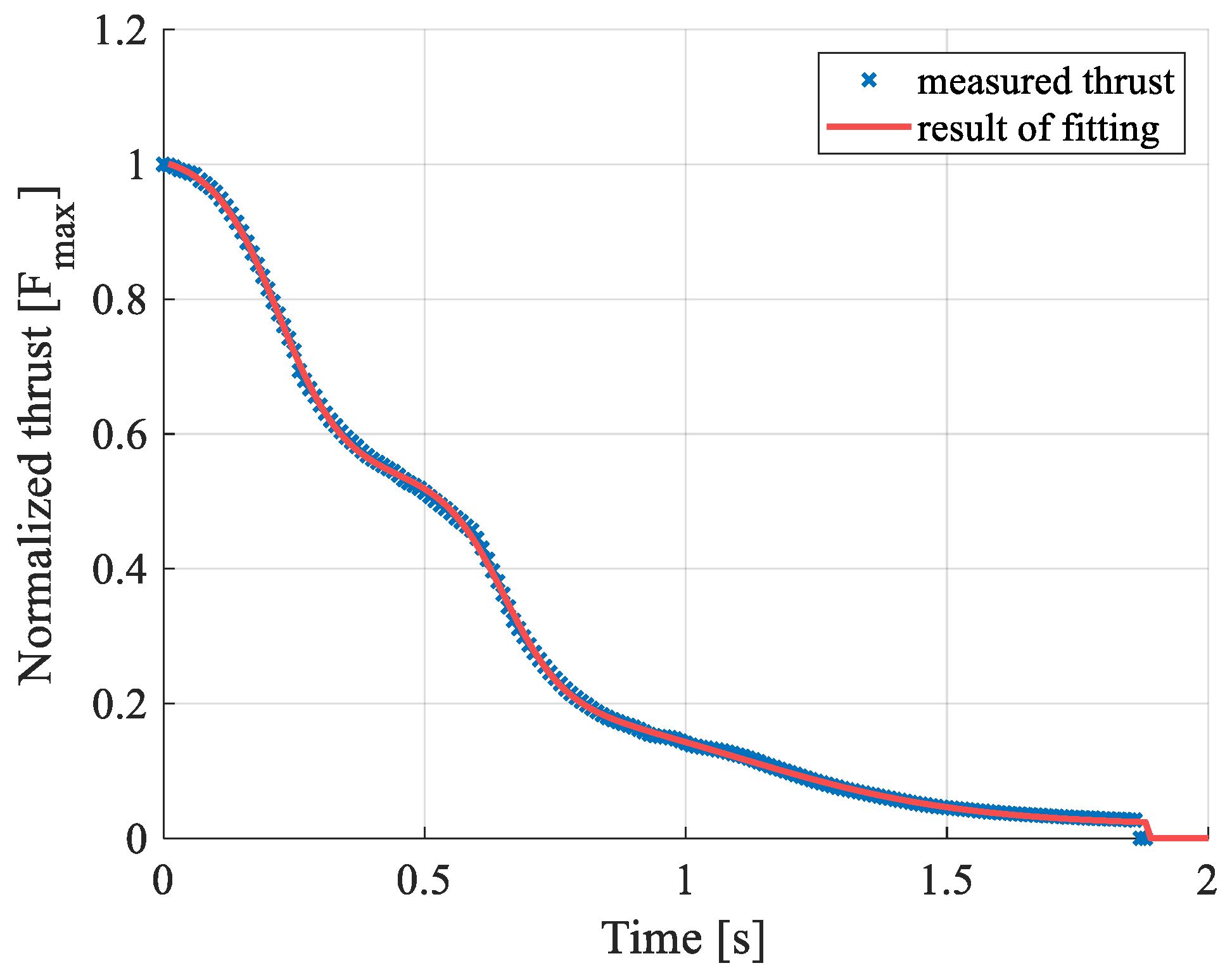
2.2. Constraints and Action Forces

The constraints and connections are shown in Figure 2. One end of both the main strut and the auxiliary struts is connected to the main body cabin by a revolute joint. The rotation axes of the two joints connecting the auxiliary struts and the main body cabin are collinear and parallel with the rotation axis of the joint between the main strut and the main body cabin, resulting in redundant constraints within this mechanism. Both auxiliary struts are rigidly fixed to the footpad. Thus, the auxiliary struts and the footpad can be treated as one part to simplify the modeling and analysis. The bottom end of the main strut is fixed on the top end of the hydro-pneumatic spring. The bottom end of the hydro-pneumatic spring is connected to the touchpad by a revolute joint. The hydro-pneumatic spring provides a nonlinear force when compressed, so it can be modeled as a translational joint with a nonlinear spring–damper force element.
In conclusion, one leg of the landing mechanism can be treated as three bodies in the modeling and analysis. The first body is the main strut with the top end of the hydro-pneumatic spring, the second body is the bottom end of the hydro-pneumatic spring, and the third one is the footpad and the auxiliary struts. The RLV has 10 DOFs (degrees of freedom) during the touchdown phase, with 6 of the main body cabin’s translation and rotation and 4 of the legs.
During the touchdown phase, RLV is mainly affected by gravity and contact force between the touchpad and the ground. Due to the sequential deactivation of the thrust system, the thrust aftereffect is applied to the main-body cabin with a stepwise decrease. In addition, lateral wind loads in the landing environment acting on the RLV should be taken into account. The thrust aftereffect resulting from a multistage engine cut-off operation [18] can be presented as a nonlinear function. Nonlinear regression is employed to model the thrust profile. The resulting nonlinear function can be expressed as
f t = p 0 + i = 1 n ( p i tanh ( α i t + β i ) )
where p i , i = 0 , 1 , , n is the magnitudes of the thrust in different stages, α i and β i determine the shape details of the thrust reference profile, and n is the number of stages during the engine cut-off operations, in this work, n = 3 .
The wind load [19] is treated as a constant force acting on the windward side of the main-body cabin. The constant wind load can be calculated as
f w = 1 2 ρ v w 2 C w S
where ρ is the density of the air, v w is the average wind velocity, C w is the drag coefficient and S is the normal equivalent area of the windward side. It is worth noting that due to the low descent speed of the arrow during the touchdown phase, air resistance can usually be ignored in the analysis of the touchdown dynamics.
For internal forces, the main components are the constraint reaction forces between joints and the nonlinear spring-damping force provided by hydro-pneumatic springs. In this work, the spring force and damping force are modeled by the Akima cubic curve-fitting method. A set of measured motions and forces are used to calculate the parameters of the fitting function. Then, in the simulation, a stiff force component and a damping one are calculated for the given compress length and velocity.

3. Dynamics Modeling of the Landing Mechanism

The dynamic modeling of the landing mechanism is discussed in this section. A rigid multibody dynamics model is established using the Cartesian coordinate method [20,21], specifically the reference point method. The floating frame method [22] is employed to model flexible bodies within the system. In the presented model, the main body, the jointed points of the struts, and the footpads are treated as rigid. On the other hand, all the slender structures of the main struts, the hydro-pneumatic springs housing, and the auxiliary struts are modeled as flexible bodies.

3.1. Kinematics of an Arbitrary Point and a Vector

The generalized coordinates of the multibody system are
q = q 1 q n b
where n b is the number of the bodies in the system. For an arbitrary rigid part B i in the landing mechanism, a set of generalized coordinates are chosen as
q i = r i θ i a i 6 + s
where r i is the position vector of the body-fixed frame, and θ i = θ 1 θ 2 θ 3 i T are the Cardan angles in the 1-2-3 body-fixed rotation sequence [23], and a i s is the vector of the truncated modal coordinates introduced to capture the deformation of flexible bodies, where s is the number of the selected first modal orders of the flexible body.
The global position of an arbitrary point P of the body B i could be defined as
r i P = r i + ρ i P = r i + ρ i P 0 + u i P = r i + A i ρ i P 0 + A i Φ i P a i 3
where ρ i P denotes the vectors from the origin of the body-fixed frame to point P expressed in the global frame after deformation. ρ i P 0 and ρ i P 0 are the vectors from the body-fixed frame to the undeformed point P 0 expressed in the global and body-fixed frame, respectively, where ρ i P 0 is constant. The symbol depicts the local expression in the body-fixed frame of a vector, so d i 3 is the local expression of d i . u i P = ρ i P ρ i P 0 is the deformation vector of point P , A i is the direction cosine matrix of B i , Φ i P 3 × s is the translational modal matrix expressed in the body-fixed frame, which is a constant matrix. For a rigid body, the deformation u i P is set to be zero, then the modal coordinates a i s vanish.
When the Cardan angles in 1-2-3 body-fixed rotation are used, the direction cosine matrix of B i is defined as
A i = C 2 C 3 C 2 S 3 S 2 S 1 S 2 C 3 + C 1 S 3 S 1 S 2 S 3 + C 1 C 3 S 1 C 2 C 1 S 2 C 3 + S 1 S 3 C 1 S 2 S 3 + S 1 C 3 C 1 C 2 i 3 × 3
where C k = cos ( θ k ) , S k = sin ( θ k ) , k = 1 , 2 , 3 .
The velocity and acceleration of the point P can be calculated by taking the first and second derivatives of Equation (5) as
r ˙ i P = r ˙ i + ρ ˙ i P 0 + u ˙ i P = r ˙ i ( ρ ˜ i P 0 + u ˜ i P ) ω i + A i Φ i P a ˙ i = r ˙ i ρ ˜ i P ω i + A i Φ i P a ˙ i
r ¨ i P = r ¨ i ρ ˜ i P ω ˙ i + A i Φ i P a ¨ i + ω ˜ i ω ˜ i ρ i P + 2 ω ˜ i A i Φ i P a ˙ i
where ω i is the angular velocity expressed in the global frame, and the relationship between ω i and the generalized velocities θ ˙ i is
ω i = K i θ ˙ i 3
where
K i = 1 0 S 2 0 C 1 C 2 S 1 0 S 1 C 2 C 1 i 3 × 3
The symbol ~ indicates that the components of the associated vector are used to generate a skew-symmetric 3 × 3 matrix [24] as
p = p 1 p 2 p 3 p ˜ = 0 p 3 p 2 p 3 0 p 1 p 2 p 1 0
To depict the rotation kinematics of the system, the global expression of an arbitrary body-fixed local vector is defined as
d i P = A i R i P d i P 3
where R i P 3 × 3 is the rotation matrix caused by local deformation of the mounted position of vector d i P .
The rotation caused by local deformation are defined as
R i P = I 3 + Ψ i P a i ˜ 3 × 3
where I 3 3 × 3 is the 3 × 3 identity matrix, and Ψ i P 3 × s is the rotational modal matrix.

3.2. Constraint Equations

In the presented system, there are two kinds of joints, the revolute joint and the cylindrical one, as shown in Figure 2.
A revolute joint between two bodies B i and B j consists of three relative displacement constraints and two relative rotation constraints. The three relative displacement constraint means that point P of body B i coincides with point Q of body B j
C ( d 3 ) = r i P r j Q = 𝟎
The two relative rotation constraints are defined as
C ( r 2 ) = d i u T d j w d i v T d j w = 𝟎
where d i u and d i v are two vectors fixed on body B i , d j w is a vector fixed on body B j in the direction of the revolute axis.
A cylindrical joint between two bodies consists of two relative displacement constraints
C ( d 2 ) = d i u T ( r i P r j Q ) d i v T ( r i P r j Q ) = 𝟎
and two relative rotation constraints, as expressed in Equation (15).
The method of Lagrange multipliers can be used to describe the constraint forces as
F c = C q T λ
where C q is the constraint Jacobian matrix and λ is a vector of the Lagrange multipliers.

3.3. Dynamic Equation

The principle of virtual work can be developed, and dynamic equilibrium condition for a free particle P implies that
δ r ˙ i P T ( m i P r ¨ i P + F i P ) = 𝟎
where F i P is the force act on the particle P , m i P is the mass of P . If the finite element method (FEM) is used to analysis a flexible body, the particle P can be replaced by a node and m i P is the lumped mass of node P .
The dynamic equation of a free flexible body B i with n P nodes can be written as
i = 0 n P δ r ˙ i P T ( m i P r ¨ i P + F i P ) δ a ˙ i T ( C i a ˙ i + K i a i ) = 𝟎
where C i and K i are modal damping and stiffness matrices of the body. The last term of Equation (19) describes the internal deformation force and damping between different nodes in the same flexible body.
With the use of Equations (7) and (8), Equation (19) leads to
δ q ˙ i T ( M i q ¨ i f i w + f i o f i u ) = 𝟎
where M i is the generalized mass matrix of the body; f i o , f i w , and f i u are the vectors of generalized external force, generalized inertial force, and generalized deformation force, respectively. It is noticeable that the generalized mass matrix includes the translational part and the rotation part as
M i = m i I 3 ω ˜ J ω
where m i is the mass of the body and J is the moment of inertia matrix. By introducing the Lagrange multipliers to describe the constraints, the dynamic equation of the body can be written as
δ q ˙ i T ( M i q ¨ i + f i w f i o + f i u + C q i T λ i ) = 𝟎
The augmented form of the dynamic equations, including constraints and forces, can be written as
M C q T C q 0 q ¨ λ = Q γ
where M is the generalized mass matrix of the system, q ¨ is the generalized acceleration, Q is the generalized force vector, and γ is the right term of the second order constraint equation. Given a set of initial conditions, the acceleration vector can be integrated to obtain the velocities and the generalized coordinates [22].

4. Numerical Simulations

Numerical simulations of the landing mechanism are performed in this section. The multibody dynamics simulation is performed with MSC Adams, and the thrust aftereffect is fitted by the nonlinear fitting library LsqFit in Julia language. The parameters of the simulation model are specified, such as mass and inertia. Several simulation cases are selected to examine the dynamic characteristics of the landing mechanism.

4.1. Parameters

The mass parameters of the landing mechanism are listed in Table 1, where the mass deviation caused by fuel residues before landing is included in the mass and moment of inertia. The mass center is at [0 m, 0 m, 5.64 m] from the bottom center of the main body cabin, where the first two coordinates are along the lateral direction and the third is along the vertical direction. The whole length of the main body cabin is about 15.4 m; thus, the height of the mass center is much lower than that of the geometric center.
The load parameters used in the model are listed in Table 2. And the normalized thrust aftereffect fitting result is shown in Figure 3, where the value 1 of the thrust equals the initial maximum thrust. It can be observed that the fitting result as Equation (1) matches well with the measured value.

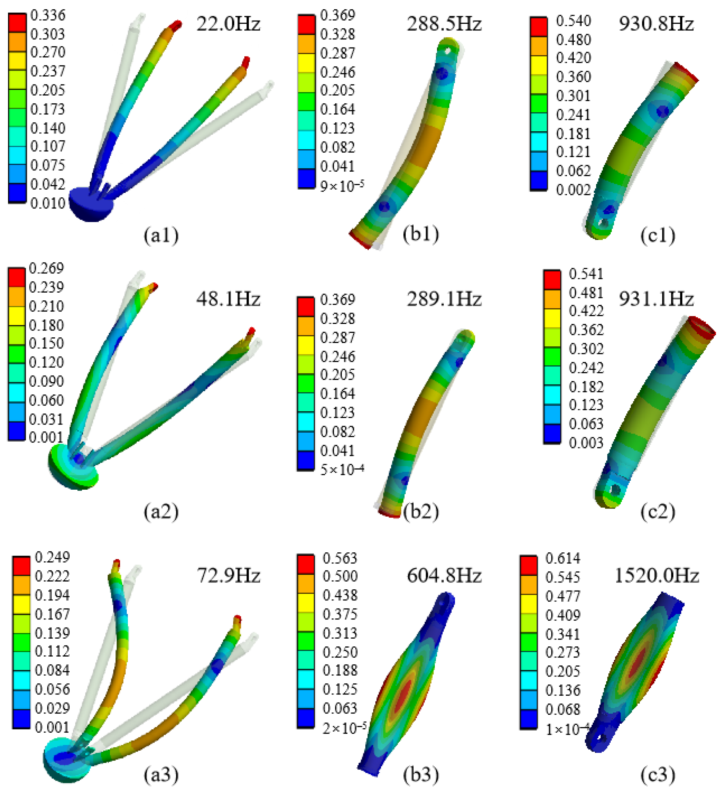
4.2. Modal Shapes of Flexible Bodies

In the floating frame formulation, several truncated modal shapes of flexible bodies are used to describe the dynamics and flexibility of RLV, and the first three modal shapes of each flexible body are illustrated in Figure 4, where different colors represent the deformations of the elements. The modal analysis is performed by the commercial software ANSYS 2020, where the tetrahedron solid elements are primarily employed for meshing. And hexahedral solid elements are adopted in regions with geometrically simple regular structures.

4.3. Simulation Cases

In order to analyze the landing dynamics, six simulation cases are conducted as follows:
  • Cases 1 and 2 are simulations for comparison between rigid and flexible models;
  • Case 3 is the simulation for a larger initial landing velocity compared with case 2;
  • Case 4 provides results for load analysis of a single landing mechanism;
  • Cases 5 and 6 are simulations for the landing stability and lateral motion analysis.
Two main landing modes are adopted as the 1-2-1 mode and the 2-2 mode [5]. The initial conditions of different simulations can be found in Table 3, which are illustrated in Figure 5, where the wind load acts on the center of pressure of the main body cabin, and the thrust aftereffect acts on the bottom center of the main body cabin. In the vertical landing, the 1-2-1 mode refers to a sequence in which one leg (leg 1 in Figure 5c) comes into contact with the ground first, followed by two legs (legs 2 and 4 in Figure 5c) making simultaneous contact, and the final leg (leg 1 in Figure 5c) makes contact with the ground. Due to the fact that all reaction forces act on only one leg, the load on the first contact phase is larger than in other modes, resulting in a higher bearing capacity in this leg compared to other landing modes. In contrast, the 2-2 mode exhibits the smallest torque caused by the contact between the ground and the footpad due to its shortest lever arm. Consequently, the stability of this mode is lowest compared to other landing modes. Based on the above analysis, we studied the two modes to investigate the dynamics characteristics and performance of the landing mechanism.

5. Discussion

Simulation results are presented and discussed in this section. The analysis began with a comparison between a rigid model and a flexible–rigid coupled model to assess the impact of flexibility on landing performance, which was followed by a comparison between cases 2 and 3 with different initial vertical landing velocities. Then, by comparing the simulation results of cases 4–6, the lateral displacement and velocity during the landing touchdown phase were analyzed. Finally, the load status during single-leg landing in case 4 was analyzed.

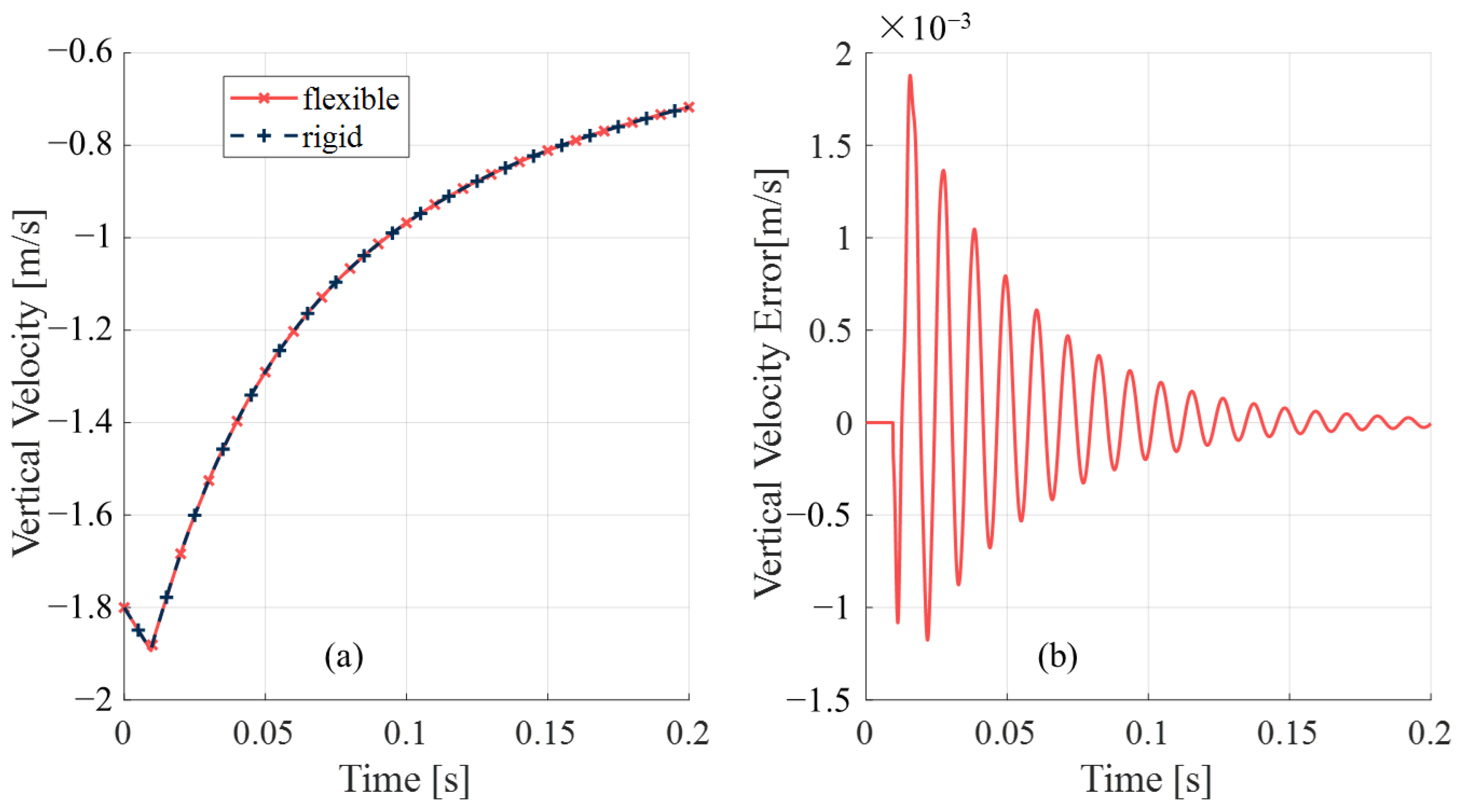
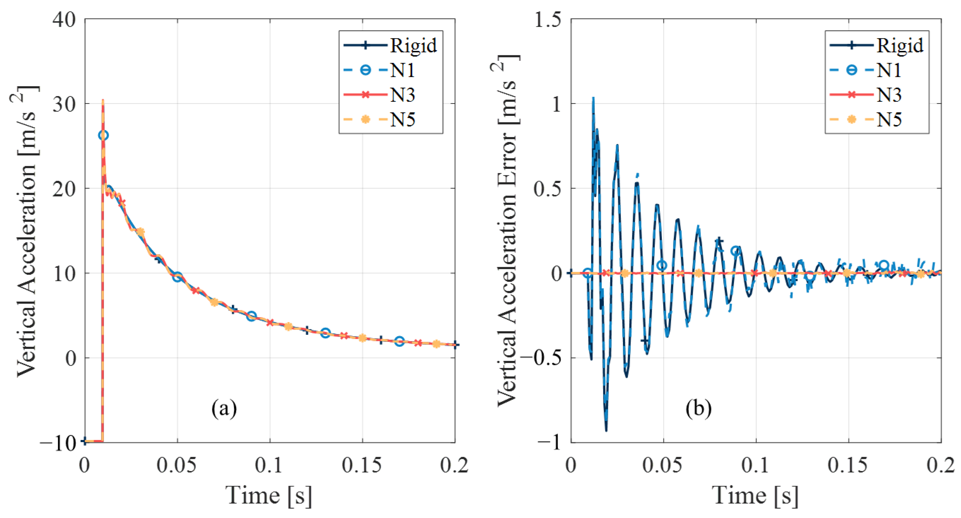
5.1. Comparison Between the Rigid Model and the Coupled One

First, the simulation results of the rigid body model in case 1 and the flexible body model with the first five modes in case 2 are compared. Since the key aspect of vertical landing is the touchdown phase after contact occurs, the following figure shows the vertical motion of the main body within 0–0.2 s. It can be observed from Figure 6 and Figure 7 that although there are no significant differences in displacement and velocity between different model simulation results, there are obvious differences in the accelerations as shown in Figure 8. The flexible body model reflects the significant vibrations caused by structural flexibility during the decay of vertical acceleration.
To further analyze the contribution of selecting different modal orders in the flexible model on simulation results, we compared the accelerations of case 2 under different modal orders: retaining no modal shape (rigid body), and one, three, or five modal shapes. In Figure 9a, Ni represents retaining the first i modal shapes, while Figure 9b shows the error between results with different modal orders and N5. It can be observed that consistent simulation results are achieved by retaining three or more modal shapes. Therefore, in subsequent simulations, we will retain the first three modal shapes of each flexible component for analysis.

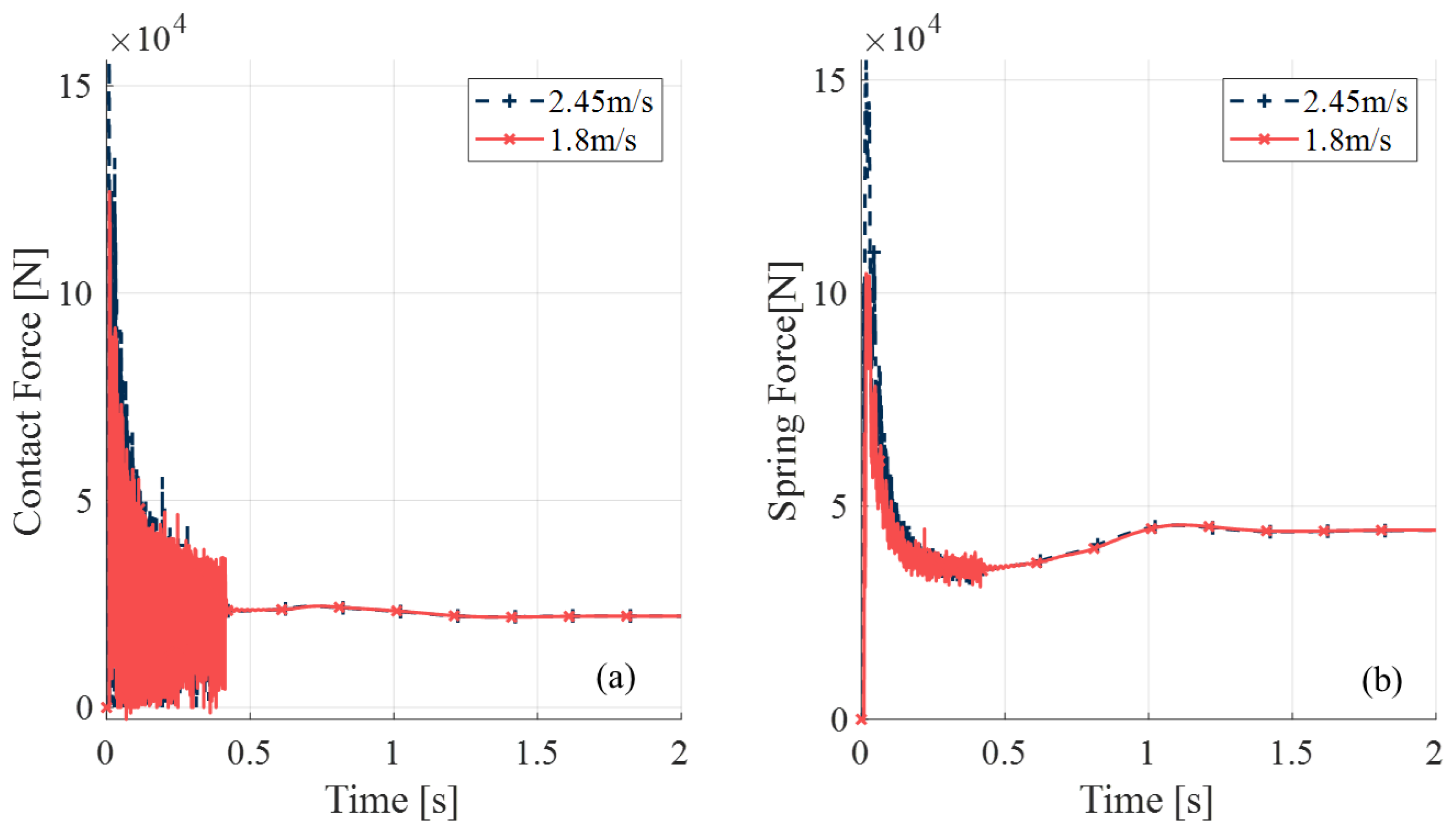
5.2. Comparison Between Different Initial Velocities

In this subsection, the influence of initial velocity is discussed by comparing the results of cases 2 and 3, where 1.8 m/s and 2.45 m/s are adopted as the initial vertical velocity according to the standards [25] in the U.S. and the test requirements [26] in China. The contact forces and spring forces are shown in Figure 10. From the comparison, it can be observed that higher initial velocity leads to larger contact force and spring compression, and the descending overall trends of the loads are similar. Due to the fact that the actual maximum initial velocity measured in the hardware test of the adopted RLV is slightly below 1.8 m/s, the initial value in the following cases is set to be 1.8 m/s.

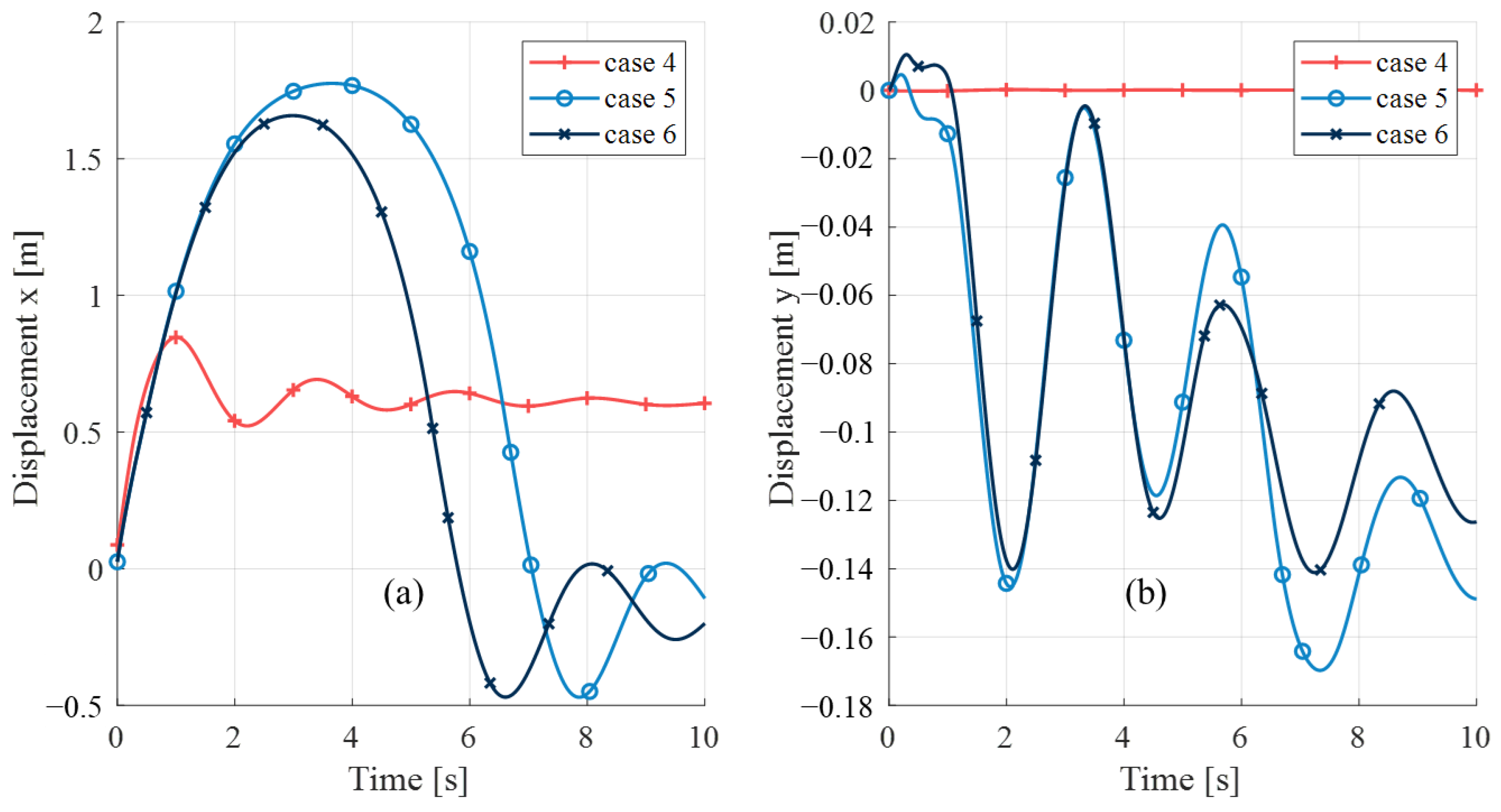
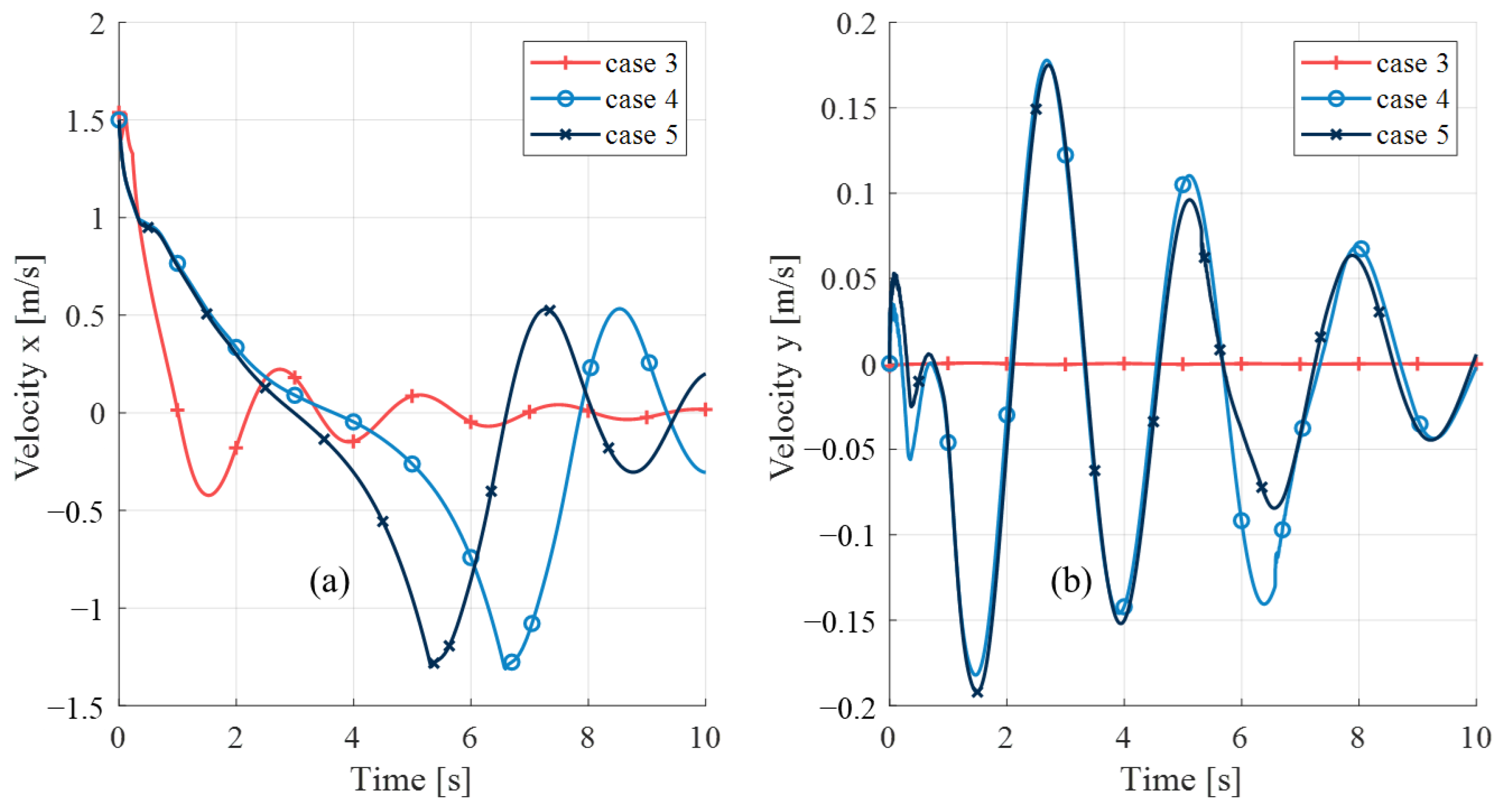
5.3. Analysis of Lateral Motion

Figure 11 and Figure 12 present the lateral displacement and velocity of the main body cabin’s center of mass during the touchdown phase under different initial conditions. As shown, for the 1-2-1 mode in case 4, since the touchpad experiences a larger moment arm, it generates a greater torque than the 2-2 mode, ultimately enabling the RLV to stabilize relatively quickly. However, under the 2-2 mode in cases 5 and 6, the lateral oscillations of the main body cabin’s center of mass are significantly more intense, and even after 10 s following the contact, stability has not been fully achieved. Additionally, there is a notable deviation between the landing point and the horizontal position of the center of mass at the initial time. The horizontal velocity of the main body cabin’s center of mass oscillates near the equilibrium position.
Therefore, the following conclusions can be drawn: under the 1-2-1 mode, the RLV achieves a stable state relatively quickly after landing. However, for landing scenarios under the 2-2 mode, the lateral vibration of the main-body cabin is more obvious, and a larger lateral landing tolerance is required than cases in other modes.

5.4. Maximum Load Analysis

Figure 13 illustrates the contact forces experienced by the four landing legs in case 4, with Figure 11b providing a detailed view from 0 to 0.3 s. As observed initially, leg 1 bears a relatively larger contact force, followed by legs 2 and 4 due to their symmetrical distribution, resulting in nearly overlapping force curves. Finally, leg 3 makes contact, leading to a gradual decrease in contact forces across all legs, as the system’s kinetic energy is consumed, ultimately converging near an equilibrium state.
The joint reaction forces and spring force are depicted in Figure 14, illustrating the complex interaction between different parts of the landing mechanism. It is observed that the initial impact is transferred to the joint of the main strut. As the touching down progresses, the hydro-pneumatic spring takes over and absorbs the impact, resulting in a smaller maximum value of the reaction force compared to the contact force. Furthermore, the reaction force on the auxiliary strut is trivial during the entire landing.
The contact forces of cases 5 and 6 are depicted in Figure 15 and Figure 16, respectively, providing a comparison with single-legged landing. It is observed that the maximum contact force values in both cases 5 and 6 are significantly smaller compared to the single-legged landing in case 4. It can be observed that in both of these operating conditions, two legs first make contact with the ground. Subsequently, after several seconds, the other two legs touched the ground. Consequently, the entire touchdown phase becomes longer, during which lateral oscillations of the main body cabin occur. Moreover, it can be seen that the contact forces of all four legs reach a stable average value at the end of the touching down in both cases 5 and 6. This stability suggests that the landing mechanism in these two cases is robust, even when starting from two-legged initial landing conditions.

6. Conclusions

This paper presents an investigation into the vertical landing mechanism of a reusable launch vehicle (RLV), with a focus on developing a comprehensive understanding of the dynamics involved. A flexible–rigid coupled dynamics model is established, allowing for simulations of the landings in various initial conditions to be conducted. Simulation results highlight the importance of considering flexibility in the main components of the landing mechanism, underscoring its critical role in achieving a successful landing. The adopted RLV design is capable of achieving stable landings under the specified initial velocity and attitude conditions, demonstrating its feasibility for practical applications. Notably, the 1-2-1 landing mode induces higher maximum values of contact force and joint reaction forces compared to other modes, highlighting the need for careful design considerations. The hydro-pneumatic spring plays a crucial role in absorbing the impact of the initial landing leg, ensuring a smoother landing experience and minimizing potential damage to the main body cabin.
Future work will focus on simulating landings on floating surfaces, such as ship decks, which pose unique challenges due to the dynamic nature of the environment. Further research is required to optimize the structure of landing mechanisms, ensuring they are designed to withstand the stresses and loads associated with different landing cases. Furthermore, the possible ranges of mass deviation and liquid sloshing issues caused by fuel residues is a vital topic in the field of landing dynamics, which need more attentions and further investigations in the future.

Author Contributions

Conceptualization, Y.Z., H.J. and H.L.; methodology, H.L. and A.H.; simulation, H.L. and W.X.; validation, C.S., W.X. and M.H.; formal analysis, C.S. and H.L.; investigation, A.H., M.H.; resources, Y.Z. and H.J.; data curation, H.L.; writing—original draft preparation, H.L.; writing—review and editing, Y.Z. and C.S.; visualization, H.L.; supervision, C.S. and H.J.; funding acquisition, H.L. All authors have read and agreed to the published version of the manuscript.

Funding

This research was funded by Fundamental Research Funds for the Central Universities [No. FRF-TP-22-026A1].

Data Availability Statement

Dataset available on request from the authors.

Conflicts of Interest

Y.Z., A.H., M.H. and H.J. are employed by Beijing Interstellar Glory Space Technology Co., Ltd., which provided the initial conditions to be simulated and partially funded the research. All other co-authors declare no conflicts of interest. These four authors contributed to the conceptualization of the study, validation, investigation, data collection, review and editing, the decision to publish the results, and manuscript revision.

References

  1. Wang, Y.; Yu, H.; Xie, J.; Yan, Z.; Tian, B.; Gao, H. The impact modeling and experimental verification of a launch vehicle with crushing-type landing gear. Actuators 2023, 12, 307. [Google Scholar] [CrossRef]
  2. Heckmann, A.; Otter, M.; Dietz, S.; Lopez, J.D. The DLR flexiblebodies library to model large motions of beams and of flexible bodies exported from finite element programs. In Proceedings of the 5th International Modelica Conference, Wien, Austria, 4–5 September 2006; pp. 85–95. [Google Scholar]
  3. Briese, L.; Acquatella, B.; Schnepper, K. Multidisciplinary Modeling and Simulation Framework for Launch Vehicle System Dynamics and Control. Acta Astronaut. 2020, 170, 652–664. [Google Scholar] [CrossRef]
  4. Thies, C. Investigation of the landing dynamics of a reusable launch vehicle and derivation of dimension loading for the landing leg. CEAS Space J. 2022, 14, 565–576. [Google Scholar] [CrossRef]
  5. Yue, S.; Lin, Q.; Zheng, G.; Du, Z. Modeling and experimental validation of vertical landing reusable launch vehicle under symmetric landing conditions. Chin. J. Aeronaut. 2022, 35, 156–172. [Google Scholar] [CrossRef]
  6. Yue, S.; Titurus, B.; Nie, H.; Zhang, M. Liquid spring damper for vertical landing reusable launch vehicle under impact conditions. Mech. Syst. Signal Process. 2019, 121, 579–599. [Google Scholar]
  7. Yue, S.; Nie, H.; Zhang, M.; Huang, M.; Zhu, H.; Xu, D. Dynamic analysis for vertical soft landing of reusable launch vehicle with landing strut flexibility. Proc. Inst. Mech. Eng. Part G J. Aerosp. Eng. 2019, 233, 1377–1396. [Google Scholar] [CrossRef]
  8. Yue, S.; Titurus, B.; Li, Z.; Wu, C.; Du, Z. Analysis of liquid spring damper for vertical landing reusable launch vehicle with network-based methodology. Nonlinear Dyn. 2023, 111, 2135–2160. [Google Scholar]
  9. Witte, L.; Buchwald, R.; Schröder, S. Touch-down dynamics and terrain interaction of planetary landing systems. In Proceedings of the Global Lunar Conference, Beijing, China, 31 May 2010; pp. 1–10. [Google Scholar]
  10. Yu, H.; Tian, B.; Yan, Z.; Gao, H.; Zhang, H.; Wu, H.; Wang, Y.; Shi, Y.; Deng, Z. Watt linkage–based legged deployable landing mechanism for reusable launch vehicle: Principle, prototype design, and experimental validation. Engineering 2023, 20, 120–133. [Google Scholar]
  11. De Oliveira, A.; Lavagna, M. Development of a controlled dynamics simulator for reusable launcher descent and precise landing. Aerospace 2023, 10, 993. [Google Scholar] [CrossRef]
  12. Mo, R.; Li, W.; Su, S. UDE-based adaptive dynamic surface control for attitude-constrained reusable launch vehicle. Nonlinear Dyn. 2024, 112, 5365–5378. [Google Scholar]
  13. Xu, S.; Guan, Y.; Bai, Y.; Wei, C. Practical predefined-time barrier function-based adaptive sliding mode control for reusable launch vehicle. Acta Astronaut. 2023, 204, 376–388. [Google Scholar]
  14. Farì, S.; Seelbinder, D.; Theil, S. Advanced GNC-oriented modeling and simulation of vertical landing vehicles with fuel slosh dynamics. Acta Astronaut. 2023, 204, 294–306. [Google Scholar] [CrossRef]
  15. Wang, C.; Chen, J.; Jia, S.; Chen, H. Parameterized design and dynamic analysis of a reusable launch vehicle landing system with semi-active control. Symmetry 2020, 12, 1572. [Google Scholar] [CrossRef]
  16. Kobayakawa, T.; Kawato, H.; Mochizuki, K.; Sakamoto, N.; Habaguchi, Y. Abort recovery strategy for future vertical landing systems. Acta Astronaut. 2015, 116, 148–153. [Google Scholar] [CrossRef]
  17. Schneider, A.; Desmariaux, J.; Klevanski, J.; Schröder, S.; Witte, L. Deployment dynamics analysis of CALLISTO’s approach and landing system. CEAS Space J. 2023, 15, 343–356. [Google Scholar] [CrossRef]
  18. Li, W.; Zhang, X.; Dong, Y.; Lin, Y.; Li, H. Powered landing control of reusable rockets based on softmax double DDPG. Aerospace 2023, 10, 590. [Google Scholar] [CrossRef]
  19. Musso, G.; Figueiras, I.; Goubel, H.; Gonçalves, A.; Costa, A.; Ferreira, B.; Azeitona, L.; Barata, S.; Souza, A.; Afonso, F.; et al. A multidisciplinary optimization framework for ecodesign of reusable microsatellite launchers. Aerospace 2024, 11, 126. [Google Scholar] [CrossRef]
  20. Shabana, A.A. Dynamics of Multibody Systems; Cambridge University Press: Cambridge, UK, 2020. [Google Scholar]
  21. Huang, G.; Zhu, W.; Yang, Z.; Feng, C.; Chen, X. Reanalysis-based fast solution algorithm for flexible multi-body system dynamic analysis with floating frame of reference formulation. Multibody Syst. Dyn. 2020, 49, 271–289. [Google Scholar] [CrossRef]
  22. Li, H.; Yu, Z.; Guo, S.; Cai, G. Investigation of joint clearances in a large-scale flexible solar array system. Multibody Syst. Dyn. 2018, 44, 277–292. [Google Scholar]
  23. Simeon, B. Computational Flexible Multibody Dynamics. A Differential-Algebraic Approach; Springer: Berlin/Heidelberg, Germany, 2013. [Google Scholar]
  24. Haug, E. Computer-Aided Kinematics and Dynamics of Mechanical Systems. In Modern Methods, 4th ed.; Ed & Carol Haug Charitable Foundation: Silver City, NM, USA, 2024; Volume 2. [Google Scholar]
  25. Shock Absorption Tests. Advisory Circular from Federal Aviation Administration, U.S. Department of Transportation, No. 25.723-1; U.S. Department of Transportation: Washington, DC, USA, 2001. Available online: https://www.faa.gov/documentLibrary/media/Advisory_Circular/AC_25_723-1.pdf (accessed on 25 March 2025).
  26. No. HB 6645-1992; Test Methods and Requirements for Drop Shock of Aircraft Landing Gear Buffers. Chinese Industry Standard: Beijing, China, 1993. Available online: https://kns.cnki.net/kcms2/article/abstract?v=_GofKS1StuQnNqplTb-m5y50A1tPD2E6Ape1oprmx-CxBLFS2M6H8EBlkqY_-JuXzusEFtUNG-fETtFtdxpvZU9zai8I5Umbyg6UDp6FjOLVRJKIaeC1MWTw7n6pqewGVER-nGDIYkf4FbJ_fb1ZBPbbuBX68GBpMCyGjCosy2BfpKS1N_lQ1QITRlE3utMT&uniplatform=NZKPT&language=CHS (accessed on 25 March 2025). (In Chinese)
Figure 1. The landing mechanism.
Aerospace 12 00280 g001
Figure 2. One leg in the landing mechanism.
Aerospace 12 00280 g002
Figure 3. Fitting result of the normalized thrust aftereffect.
Aerospace 12 00280 g003
Figure 4. The first three modal shapes of flexible bodies, (deformation unit: m): (a1a3) the first three modal shapes of the auxiliary strut with footpad, (b1b3) the first three modal shapes of the main strut, (c1c3) the first three modal shapes of the spring housing.
Aerospace 12 00280 g004
Figure 5. Initial conditions of the landing simulation: (a) 1-2-1 mode used in case 4, (b) 2-2 mode used in cases 5 and 6, (c) top view of the 1-2-1 mode, (d) top view of the 2-2 mode.
Aerospace 12 00280 g005
Figure 6. Vertical displacement of the flexible and the rigid model: (a) displacement, (b) error between the two model.
Aerospace 12 00280 g006
Figure 7. Vertical velocity of the flexible and the rigid model: (a) velocity, (b) error between the two model.
Aerospace 12 00280 g007
Figure 8. Vertical acceleration of the flexible and the rigid model: (a) acceleration, (b) error between the two models.
Aerospace 12 00280 g008
Figure 9. Vertical acceleration of the flexible model with different orders of selected modal shapes: (a) acceleration, (b) error compared with the results of N5.
Aerospace 12 00280 g009
Figure 10. Contact and spring forces of different initial vertical velocities: (a) contact force, (b) spring force.
Aerospace 12 00280 g010
Figure 11. Lateral displacement of the main-body cabin: (a) displacement along x direction, (b) displacement along y direction.
Aerospace 12 00280 g011
Figure 12. Lateral velocity of the main body cabin: (a) velocity along x direction, (b) velocity along y direction.
Aerospace 12 00280 g012
Figure 13. Contact force in each leg of case 4: (a) contact force in 0-10s, (b) detailed view of contact force in 0–0.3s.
Aerospace 12 00280 g013
Figure 14. Forces in leg 1 of case 4.
Aerospace 12 00280 g014
Figure 15. Contact force in each leg of case 5.
Aerospace 12 00280 g015
Figure 16. Contact force in each leg of case 6.
Aerospace 12 00280 g016
Table 1. Mass parameters of the landing mechanism.
PartMass (kg) I x x I y y I z z
Main body cabin8325.38 kg1.628 × 105 kgm21.629 × 105 kgm29.37 × 103 kgm2
Main strut43.64 kg7.47 kgm27.46 kgm20.16 kgm2
Auxiliary strut191.70 kg65.8 kgm255.3 kgm21.18 kgm2
Spring28.38 kg2.55 kgm22.54 kgm20.075 kgm2
Table 2. Load parameters of the landing mechanism model.
ParameterValueParameterValue
Wind velocity10 m/sContact stiffness1 × 108 N/m
Drag factor0.9Contact damping1 × 107 Ns/m
Windward area45.3 m2Contact radius0.2 m
Air density1.29 kg/m3Contact exponent2.0
Static friction0.6Dynamical friction0.4
Table 3. Initial conditions.
CaseVertical
Velocity
Lateral
Velocity
Initial
Orientation
Angular
Velocity
Thrust
Aftereffect
Wind Load
11.8 m/s0 m/s[0, 0, 0]°[0, 0, 0]°/snono
21.8 m/s0 m/s[0, 0, 0]°[0, 0, 0]°nono
32.45 m/s0 m/s[0, 0, 0]°[0, 0, 0]°nono
41.8 m/s−1.5 m/s[0, 4, 0]°[0, 4, 0]°/snoyes
51.8 m/s−1.5 m/s[45, 4, 0]°[0, 4, 0]°/syesyes
61.8 m/s−1.5 m/s[45, 4, 0]°[3, 4, 0]°/syesyes
Disclaimer/Publisher’s Note: The statements, opinions and data contained in all publications are solely those of the individual author(s) and contributor(s) and not of MDPI and/or the editor(s). MDPI and/or the editor(s) disclaim responsibility for any injury to people or property resulting from any ideas, methods, instructions or products referred to in the content.

