Article

Vibration Isolation in Stewart Platforms via Phase-Change Low-Melting-Point Alloys for Tunable Stiffness

1
Beijing Institute of Technology Chongqing Innovation Center, Chongqing 401120, China
2
School of Aerospace Engineering, Beijing Institute of Technology, Beijing 100081, China
3
Southwest Institute of Technical Physics, Chengdu 610041, China
*
Author to whom correspondence should be addressed.
Aerospace 2025, 12(4), 279; https://doi.org/10.3390/aerospace12040279
Submission received: 25 February 2025 / Revised: 20 March 2025 / Accepted: 25 March 2025 / Published: 27 March 2025
(This article belongs to the Section Astronautics & Space Science)

Abstract

:
Micro-vibration mitigation is critical for spacecraft conducting precision-oriented space missions. In this paper, a novel Stewart platform incorporating a phase-change low-melting-point alloy (LMPA) is developed to achieve temperature-dependent stiffness modulation and broadband vibration isolation. First, based on the theory that variable stiffness alters the natural frequency of the structure, the feasibility of using the Stewart platform to achieve vibration isolation by changing the stiffness is obtained. Subsequently, a new Stewart composite structure was engineered by integrating LMPA and composite materials. Finally, compression and vibration tests were carried out on these platforms at temperatures of 25 °C and 60 °C. The results show that these Stewart platform composite structures have the response characteristics of variable stiffness, a variable natural frequency and widened frequency at different temperatures. The response properties of the platform are attributed to the phase change of the low-melting-point alloy at different temperatures. The effective vibration isolation frequency range of the composite Stewart platform can be widened to 31.6 Hz, and the vibration attenuation can reach up to 10 dB. This investigation establishes a novel methodology for developing adaptive vibration isolation systems using phase-change alloys, which are particularly suitable for spacecraft applications requiring precision motion control.

1. Introduction

With the rapid global advancement of aerospace technology in the 21st century, numerous spacecraft equipped with high-precision instruments have been deployed into space [1]. Spacecraft platforms are increasingly adopting integrated, large-scale, and highly flexible configurations [2]. This trend has led to a significant increase in the overall structural instability of spacecraft, and the problem of structural vibrations caused by disturbances has become increasingly prominent. The flexible parts on the spacecraft, such as solar panels [3], momentum wheels [4], refrigerants [5], etc., can easily cause spacecrafts to vibrate when undertaking normal operations [6]. In addition, due to the very small damping of the space environment on the spacecraft, these vibrations may last for a long time. These unfavorable vibrations on the spacecraft are characterized by a small amplitude, wide frequency band, sensitivity, and inherent existence, and they are also difficult to measure [7]. If these unfavorable vibrations are not suppressed, they will seriously affect the normal movement of the spacecraft and the accurate imaging of satellites [5]. Therefore, in order to ensure the normal operation of the spacecraft, it is necessary to control the induced micro-vibrations.
In spacecraft equipment, Stewart platform composite structures are most commonly used as the vibration isolation structure [8]. In 1993, NASA first proposed the application of the Stewart platform for the vibration isolation of high-resolution optical payloads to suppress micro-vibrations in spacecraft [9]. This Stewart platform is usually used as a connecting device between the payload and the spacecraft body, to reduce or eliminate micro-vibrations transmitted to the payload and achieve the isolation of micro-vibrations [10]. The Stewart platform integrates the advantages of intelligent materials and exhibits significant features such as a compact structure, strong fault tolerance, excellent bearing capacity, high pointing accuracy, and stable dynamic characteristics [11,12,13].
According to the basic principle of active isolation technology, the stiffness or damping of the isolation structure can be changed to achieve an isolation effect [14]. In practical use, the upper and lower platforms of the Stewart isolation platform are used to connect the spacecraft body structure and do not have adjustable stiffness and damping. Therefore, for the variable stiffness or variable damping design of the Stewart platform, only the drive column can be optimized. According to the structural stiffness of the actuator, the Stewart platform composite structures used in aerospace are classified into rigid Stewart platform composite structures and flexible Stewart platform composite structures. The rigid Stewart platform composite structures usually adopt a piezoelectric actuator and a magneto strictive alloy actuator. These rigid actuators are individually or synergistically used with flexible springs. Flexible Stewart platform composite structures usually use soft actuators, such as voice coil motors, which are used in parallel with soft springs [6]. In recent years, the development of new variable stiffness technology has been rapid, and many experts and scholars have conducted in-depth research on it [15].
High-static low-dynamic-stiffness struts were constructed by Zheng; the constructed struts improved the isolation performance of the passive Stewart platform composite structures. The resonance frequencies of the platform can be reduced effectively without having a detrimental impact on its load bearing capacity [16]. A Stewart platform composite structure with a piezoelectric actuator for the isolation of micro-vibrations was studied by Wang. The results show that the Stewart platform composite structure could achieve the attenuation of 30 dB periodical disturbances and of 10–20 dB random disturbances in the frequency range of 5–200 Hz [17]. Wu devised a Stewart platform composite structure constructed using six X-shaped structures as legs; the platform achieved very good and tunable vibration isolation performance in all six directions [18]. The results show that the same isolation efficiency can be achieved with much lower static deflection and, hence, space when using a negative stiffness magnet spring compared to a linear spring. An adjustable electromagnetic negative stiffness Stewart platform composite structure was proposed by Wang, in which the platform was able to reduce the natural frequency and widen the frequency range [19].
While substantial progress has been made in active control algorithms for Stewart platforms [20,21,22,23], limited attention has been devoted to structural innovation in these systems. With the rise of low-melting-point alloys (LMPAs) [24] and the in-depth study of the variable stiffness design of liquid metal [25,26,27,28], there is the potential for liquid metal to be used as the driving column for Stuart platforms, utilizing the phase transition characteristics of LMPA to achieve stiffness changes in the overall structure. The phase transition refers to the phase change of materials: that is, LMPA can achieve the transition between solid and liquid states in environments below or above its melting point temperature. Moreover, Liu has preliminarily completed the preparation of a Stewart platform with an LMPA-driven column [29].
In this study, in order to effectively suppress the micro-vibrations in the normal operation of the spacecraft, a new Stewart platform with temperature-controllable variable stiffness and vibration-damping functions was designed by applying the phase-change characteristics of LMPA at different temperatures. First, based on the theory that variable stiffness can change the natural frequency of the structure, the feasibility of using a Stewart platform to achieve vibration isolation by changing the stiffness is determined. Then, a new Stewart platform composite structure is designed based on the characteristics of driving the isolation of variable-stiffness vibrations. Finally, the mechanical properties and vibration characteristics of the Stewart platform composite structure were tested experimentally. The results indicate that the Stewart platform structure can exhibit a large natural frequency band gap under temperature driving and realize the function of vibration isolation. The introduction of LMPA as the variable-stiffness driving column of the Stewart platform structure can provide new ideas for the application of LMPA in the field of vibration isolation in the future.

2. Variable-Stiffness Vibration Isolation and Design Ideas

2.1. Variable-Stiffness Vibration-Damping Foundation

Taking a typical linear vibration system with a single degree of freedom as an example [30], the working process of the Stewart platform is described. The typical vibration system with a single degree of freedom is shown in Figure 1. In the figure, m is the quality of the Stewart’s vibration isolation platform, k is the stiffness coefficient of the system, and c is the damping coefficient of the system. When the excitation force on the Stewart isolation platform is F 0 t , the displacement generated by the platform on the Stewart isolation platform is x .
According to the D’Alembert principle, the differential equation of a vibration system with a single degree of freedom is obtained:
m x ¨ t + c x ˙ t + k x t = F 0 t
After applying the Laplace transformation, assuming that the initial velocity and acceleration are 0, it can be deduced that:
m s 2 X s + c s X s + k X s = F 0 s
When the force transmitted to the fixed end is F o u t , the transfer function obtained after passing through the Stewart isolation platform is:
T f s = F o u t s F 0 s = c s + k m s 2 + c s + k
When the excitation force is F 0 t = F 0 sin ω t , the above equation can be changed to [31]:
T f i ω = F o u t i ω F 0 i ω = c i ω + k m i ω 2 + c i ω + k = c i ω + k m i ω + k m ω 2
If the natural frequency is ω n = k m , the damping ratio is ξ = c 2 m k , and the circular frequency ratio of the excitation frequency ω to the natural circular frequency ω n of the isolation system is λ = ω ω n , then the above equation is:
T f i ω = 1 + i 2 ξ λ 1 λ 2 + i 2 ξ λ
The force transfer rate of the Stewart platform is:
T f = T f i ω = 1 + 4 ξ λ 2 1 λ 2 2 + 4 ξ λ 2
For a variable-stiffness isolation system used in vibration isolation technology, the natural frequency of the isolation system can be modulated by actively adjusting its stiffness to suppress spacecraft micro-vibrations. According to Equation (6), the relationship between the force transfer rate and stiffness of the variable stiffness isolation system can be obtained:
T f = k 2 + c 2 ω 2 k ω 2 m 2 + c 2 ω 2
According to Equation (7), at a certain excitation frequency, the force transmission rate T f can be adjusted by adjusting the mass m , stiffness k , and damping c of the isolation system.
Assuming that the damping of the selected material is 0.1 and the mass is also 1, the relationship between the force transmission rate of the isolation system and the excitation force frequency at different stiffness levels can be obtained, as shown in Figure 2. As shown in the figure, as the stiffness of the isolation system increases, the frequency and amplitude of resonance will both increase. Therefore, the harmful frequency of the excitation force system can be avoided by actively adjusting the stiffness of the isolation system. Therefore, in engineering, a change in the stiffness of the Stewart isolation system can be actively controlled to isolate the excitation force and prevent the occurrence of resonance phenomena.

2.2. Temperature-Controlled Phase Transition

Based on the response characteristics of a linear vibration system with a single degree of freedom, a dynamic model of the variable stiffness Stewart platform was established using the Newton–Euler method. In the practical application of spacecraft vibration isolation, the Coriolis and centrifugal terms are neglected due to the small-amplitude vibration assumption in microgravity environments [32].
The dynamic equation for the Stewart vibration isolation platform is [33]:
M χ ¨ + C χ ˙ + K χ = F
where the inertia matrix M is defined as follows:
M = M x + J T M s J M x = m s I 3     I M s = diag m 1 , m 2 , m 3 , m 4 , m 5 , m 6
where m s is the mass of the Stewart platform load, J is the Jacobian matrix, I 3 is the inertia matrix of the Stewart platform in three directions, and m i is the mass of each driving column of the Stewart platform.
The damping matrix C is specifically defined as follows:
C = J T C ¯ J C ¯ = diag c 1 , c 2 , c 3 , c 4 , c 5 , c 6
where c i is the damping coefficient of each drive column of the platform.
Similarly, the stiffness matrix K is specifically defined as follows:
K = J T K ¯ J K ¯ = diag k 1 , k 2 , k 3 , k 4 , k 5 , k 6
where k i is the equivalent stiffness coefficient for each drive column of the platform.
Similarly, the generalized driving force F matrix is defined as follows:
F = J T f J f = diag f 1 , f 2 , f 3 , f 4 , f 5 , f 6
where f i represents the driving force of each driving column on the Stewart platform.
For the solution of the transfer function through the Stewart isolation platform, we can refer to the force transfer rate calculation process of a linear vibration system with a single degree of freedom.
Similarly, we first assume that the output force after passing through the Stewart isolation platform is:
F S - out = C χ ˙ + K χ
The transfer function T S through the Stewart isolation platform is:
T S = F S - out F = C χ ˙ + K χ M χ ¨ + C χ ˙ + K χ
After the Laplace transform, it can be determined that:
T S s = C s + K M s 2 + C s + K
The matrix in the above equation is a determinant of 6 × 6. To solve Equation (15), the process is as follows:
Assuming X 1 = χ , X 2 = X ˙ 1 , then X 2 = χ ˙ , X ˙ 2 = χ ¨ .
Substituting the above assumption into Equation (8) yields:
M X ˙ 2 + C X 2 + K X 1 = F
After simplification, it can be concluded that:
X ˙ 2 = M 1 F C X 2 K X 1
Similarly, Equation (13) can be simplified as:
F S - out = C X 2 + K X 1
Now, we combine Equations (17) and (18) into the state space expression of the system:
X ˙ 2 = M 1 F C X 2 K X 1 F S - out = C X 2 + K X 1
After unfolding, it can be concluded that:
X ˙ 2 = 0 I M 1 K M 1 C X 1 X 2 + 0 M 1 F F S - out = K C X 1 X 2
From this, the transfer function T S can be obtained as follows:
T S ( s ) = M 1 ( s I M 2 ) 1 M 3 T S s = M 1 s I M 2 1 M 3
where M 1 = K C , M 2 = 0 I M 1 K M 1 C , M 3 = 0 M 1 .

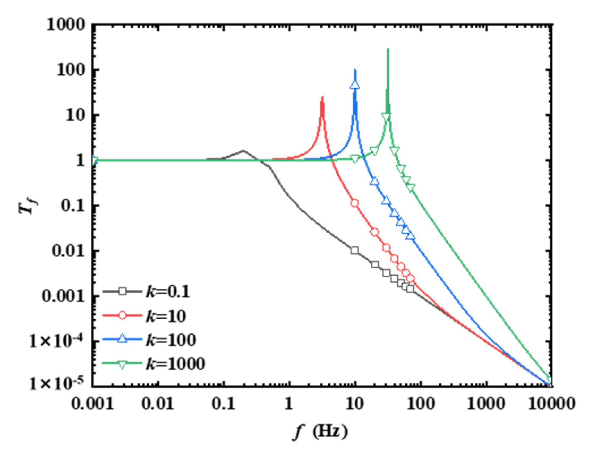
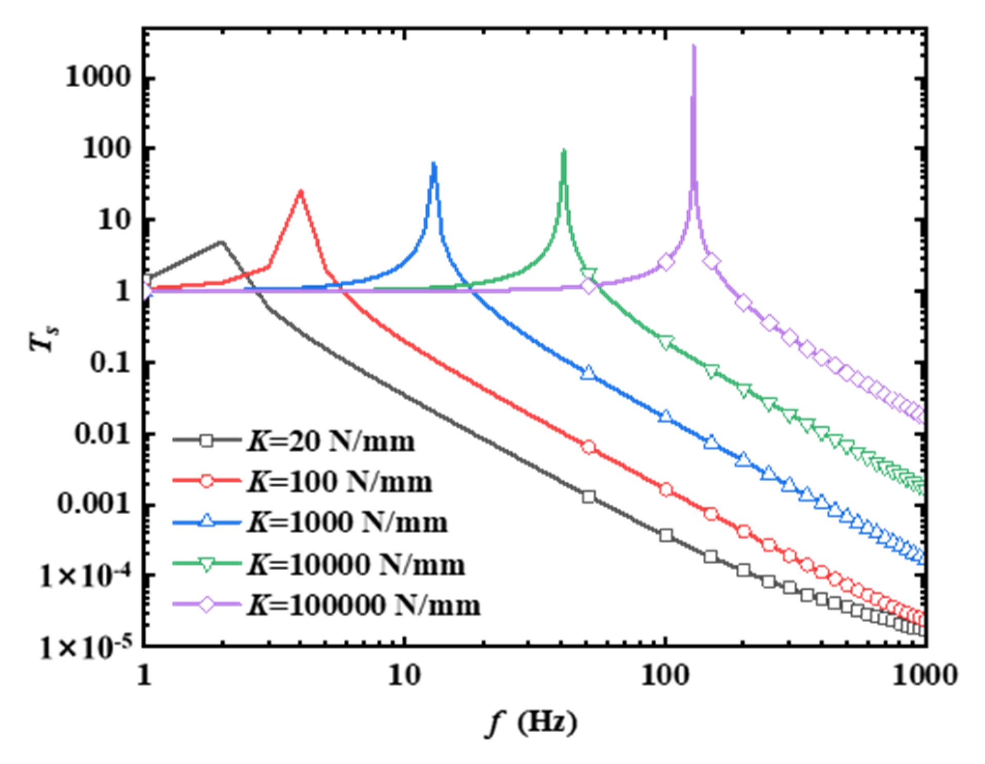
2.3. Variable-Stiffness Vibration Isolation Characteristics of the Stewart Platform

In order to analyze the effect of the stiffness coefficient K of the driving column in the variable-stiffness Stewart platform on the transfer function T S of the entire variable-stiffness Stewart platform, it is assumed that the six driving columns in the variable-stiffness Stewart platform are consistent, with a length of L = 10.0 mm, a mass of m i = 1.0 kg, a damping coefficient of c i = 0.1 Ns/mm, an angle of θ = 60.0 ° between the driving column and the upper platform, and a load mass of m s = 6.0 kg on the upper platform. Based on the basic theory of the variable-stiffness Stewart platform, the relationship between the driving column coefficient K and the transfer function T S can be obtained. The driving column stiffness coefficients K were selected as 20.0 N/mm, 100.0 N/mm, 1000.0 N/mm, 10,000.0 N/mm, and 10,000.0 N/mm, in order to explore the effect of the driving column stiffness coefficient K on the vibration isolation characteristics of the variable-stiffness Stewart platform in the frequency range 1.0 Hz~1000.0 Hz, as shown in Figure 3.
Figure 3 shows that, as the drive column stiffness coefficient K increases, the vibration response transmissibility of the variable-stiffness Stewart isolation platform increases gradually, as does its resonant frequency. This is consistent with the law of the effect of the stiffness coefficient on the vibration characteristics in a linear vibration system with a single degree of freedom. Therefore, the resonant frequency of the variable-stiffness Stewart platform can be changed by actively controlling the change in the stiffness coefficient of the system during engineering; moreover, the vibration isolation frequency band of the variable-stiffness Stewart platform can be widened to avoid the harmful frequencies of the exciting force system. This provides a theoretical basis for the subsequent study of the vibration isolation characteristics of the variable-stiffness Stewart platform.

3. Experimental Program of the Samples

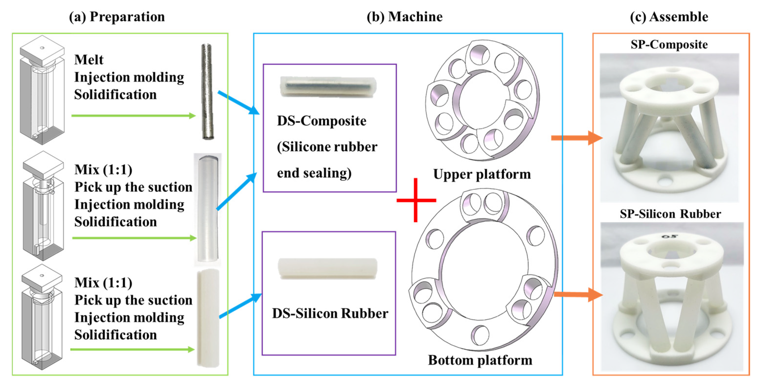
3.1. Preparation Process

In order to verify the feasibility of the vibration isolation theory of the variable-stiffness Stewart platform, the platform was prepared based on the LMPA and verified through testing. The process of preparing the test samples is depicted in Figure 4, and the prepared samples were integrated to create the novel Stewart platform composite structure. Figure 4a shows the process of preparing the cylindrical low-melting-point alloy rod (C-LMPA, the adopted LMPA is the bismuth–tin–indium alloy (Bi57%-Sn26%-In17%), the melting point of which is 50 °C), the hollow silicone rubber column, and the solid silicone rubber column. The selected LMPA (melting point 50 °C) is encapsulated within silicone rubber to ensure structural integrity in extreme temperatures (−50 °C to 150 °C), validated via thermal cycling tests. The preparation process of C-LMPA is concluded wit the three following steps: melting, injection molding, and re-solidification. The hollow silicone rubber column and the solid silicone rubber column were prepared by mixing two parts of silicone rubber A and B (Dragon Skin 30) with equal weight. The mixture was further subjected to a vacuum for a period of 10 min to de-air, and then it was poured into the molds with a syringe and cured at room temperature [34]. Then, the prepared C-LMPA was added into a hollow silicone rubber column. Both ends of the composite driving column (DS-Composite) were sealed with silicone rubber, as shown in Figure 4b. Finally, the prepared DS-Composite and silicone rubber driving column (DS-Silicon Rubber) were assembled with the upper platform and the bottom platform respectively, and the Stewart platform composite structure was finally obtained, as described in Figure 4c. The performance parameters of the materials used in the sample preparation process are shown in Table 1.

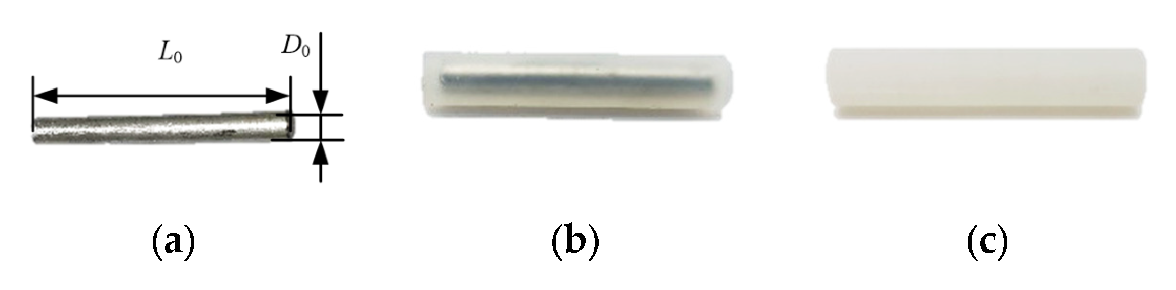
3.2. Parameters of the Driving Column

The structural parameters of the driving column are shown in Table 2. The height of each driving column is 50 mm. The diameter of the DS-Composite and DS-Silicon Rubber is 10 mm, while the diameter of C-LMPA is 5 mm. C-LMPA was produced at 50 °C with LMPA according to the above preparation process, as shown in Figure 5a. The DS-Composite was made of LMPA and silicone rubber, the thickness of the silicone wall was 2.5 mm, and both ends of the DS-Composite were capped with silicone, as shown in Figure 5b. DS-Silicon Rubber was made of silicone rubber (Dragon Skin 30), as shown in Figure 5c. These different types of driving columns were devised as the main support, variable-stiffness, and vibration isolation aspects of the Stewart vibration platform.

3.3. Parameters of Stewart Platform Composite Structure

The upper and bottom platforms of the Stewart platform composite structure are made of JS-UV-2018-2 (a low-viscosity photosensitive resin material) with 3D printing technology. The total height of the upper and lower platforms is 7.5 mm, the thickness of the bottom surface is 3 mm, the height of the small boss is 4.5 mm, and the angle between the drive column groove and the plane is 64°. The diameter of the upper platform is 60 mm, and that of the bottom platform is 80 mm. The total height of the Stewart platform composite structure is 50 mm, and it is assembled from six driving columns of the same type. The driving columns were installed in the circular grooves of the upper platform and bottom platforms, and they cross each other in pairs to form a triangle. A typical platform is shown in Figure 4c. The Stewart platform composite structure, with a stable structure of the triangular driving column, can achieve the vibration isolation with the controllable driving column’s stiffness.

4. Test of the Samples

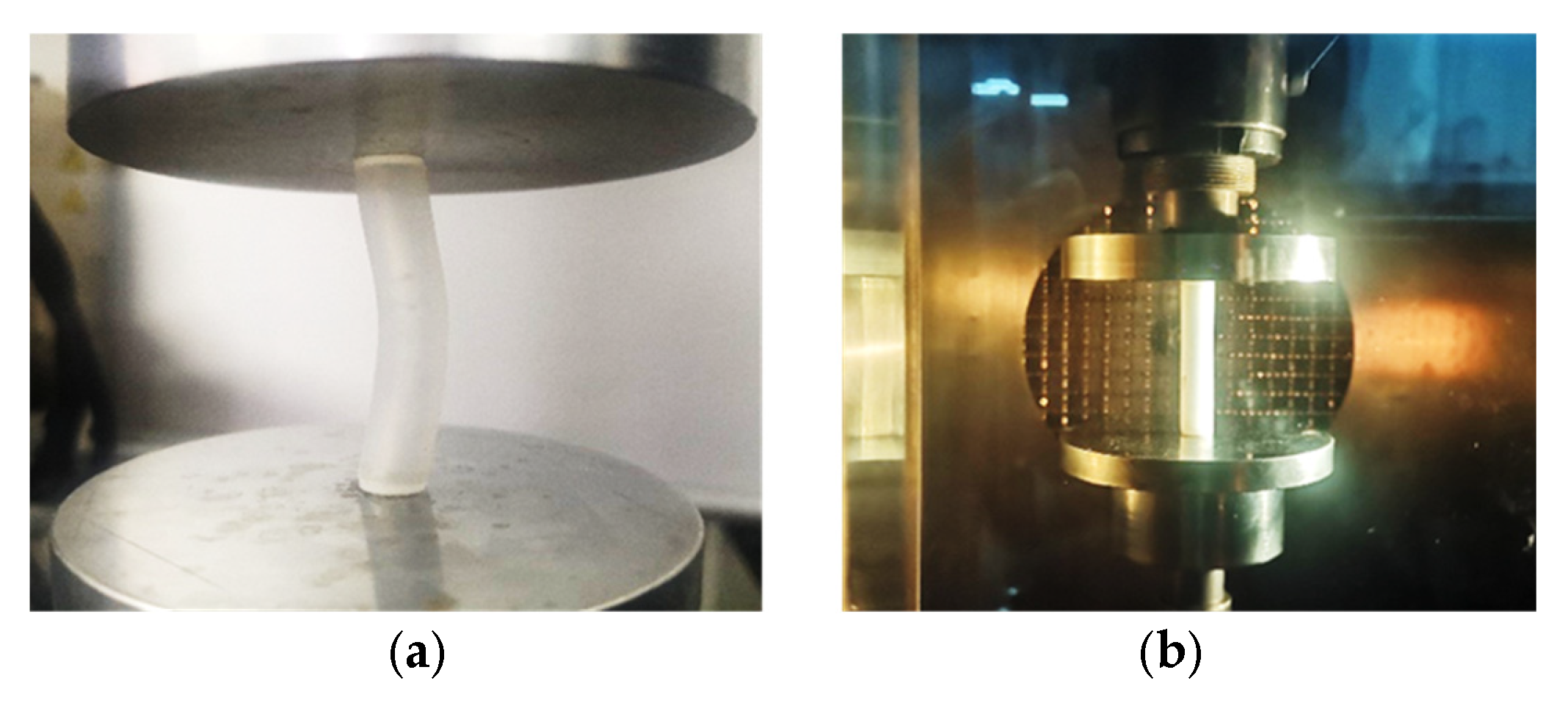
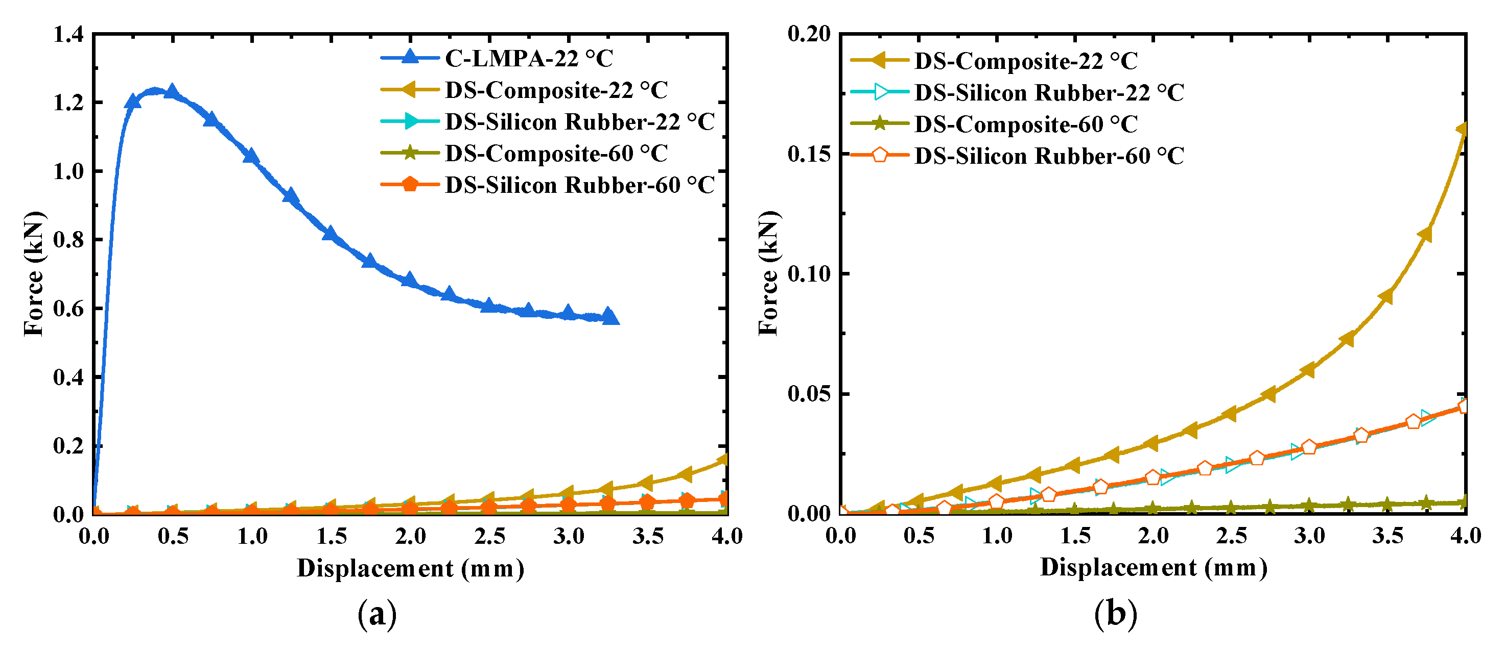
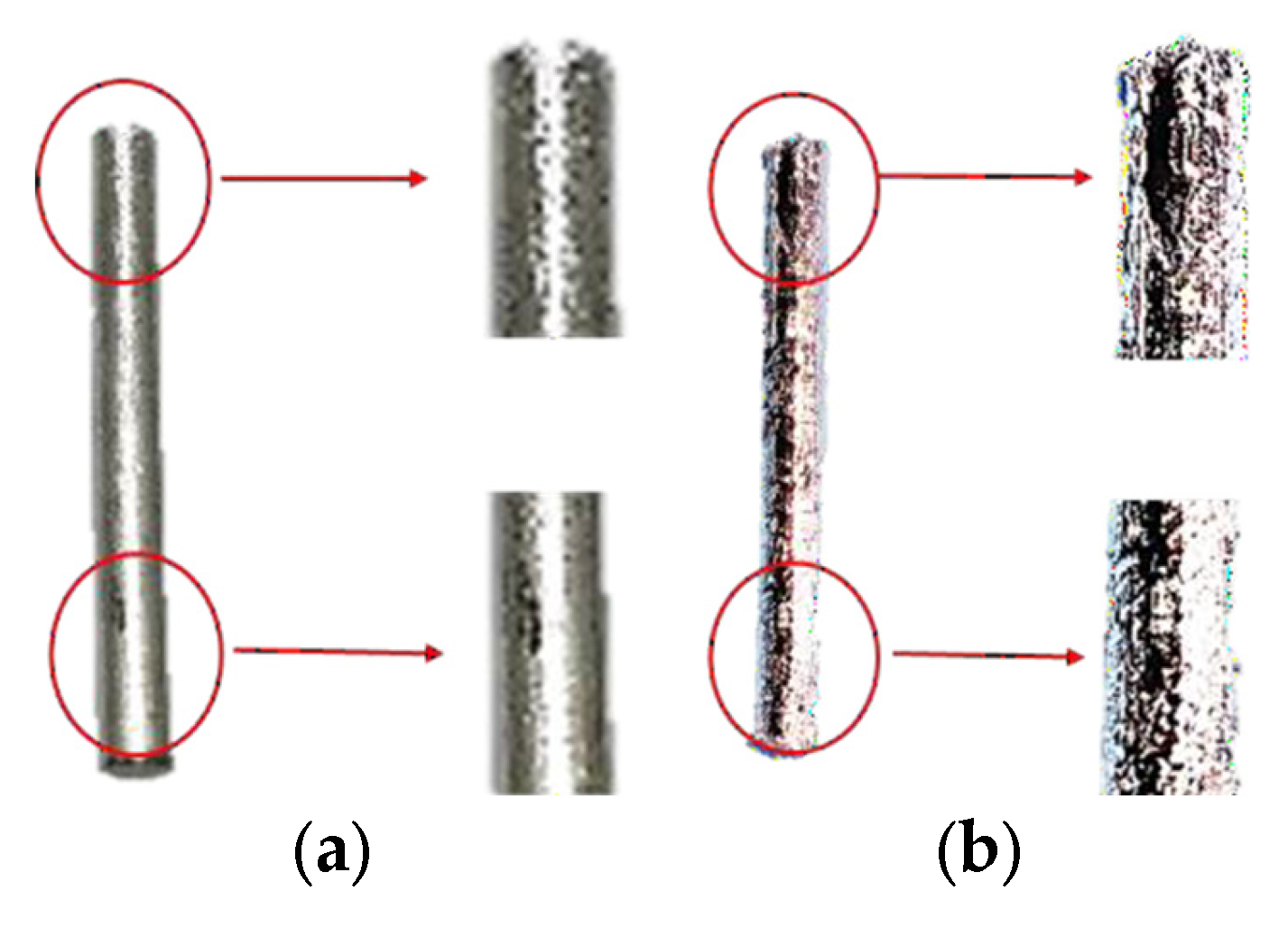
4.1. Compression Test of the Driving Column

In order to study the compression performance of different driving columns at different temperatures, the compression modulus of the driving columns was measured using a compression testing machine with an environmental box. Temperature was controlled within ±0.5 °C using a PID-regulated environmental chamber. The specific compression test with temperature control is shown in Figure 6b. The driving column was installed on a test bench in the temperature-controlled box (with a size if 400 mm × 400 mm × 560 mm) that was isolated from the external temperature. The ambient temperature was set for testing, and the compression testing machine with an environmental chamber used a PID control algorithm to dynamically adjust the heating/cooling equipment based on the signals obtained from temperature sensors arranged at multiple points inside the chamber; this allowed for rapid temperature adjustments inside the temperature control chamber. The dimensions of the driving columns are shown in Table 3. Different driving columns were tested at the isothermal temperatures of 22 °C and 60 °C, with the loading rate set to 0.5 mm/min. Part of the test process is shown in Figure 6.
By conducting compression tests, the compressive force-displacement curves of different driving columns at different temperatures were obtained, as shown in Figure 7. According to [35], the empirical equation of compression modulus E c is obtained using the following equation:
E c = 4 π × F c L c × L 1 D 1 2
where F c is the compression force of the driving column, L c is the compressed displacement of the driving column, L 1 is the actual height of the driving column, and D 1 is the actual diameter of the driving column.
The straight-line segment in the elastic deformation stage in Figure 7 is based on three measurements, and the compressive modulus is calculated using Equation (22), as shown in Table 4. Among the different types of driving columns, the C-LMPA exhibited the largest compression modulus of 3795.4 MPa at 22 °C, indicating that it can behave like a metal. The lower compressive modulus of the DS-Composite is 9.4 MPa at 22 °C, which is due to the ends of the DS-Composite being wrapped with a layer of 2.5 mm-thick silicone rubber. The silicone rubber thus always absorbs some of the compression energy when compressed. DS-Silicon Rubber has the smallest compressive modulus of 1.1 MPa at 22 °C, as it exhibits remarkable hyper-elasticity properties when compressed, as shown in Table 4. From Figure 7, we can conclude that the compressive force of C-LMPA first increases and then decreases with the increase in compressive displacement. This is because the C-LMPA turn would bend when the loaded compression displacement is over the maximum compression limit. In addition, the maximum supporting force of C-LMPA with a diameter of 5 mm and a length of 10 mm is 1.22 kN.
Comparing different types of driving column, the compressive modulus of the DS-Composite is the smallest at 60 °C, as shown in Figure 7. This is because the phase transition of the LMPA inside the driving column induces a change in the modulus of the driving column. At 60 °C, the loaded temperature exceeds the melting point of LMPA, meaning that the LMPA becomes liquid. When the DS-Composite is compressed, the silicone rubber material of the outer layer is mainly affected by the compression. The DS-Composite has a sandwiched structure, while DS-Silicon Rubber is an integral structure with a relatively stable skeleton. The compressive modulus of the DS-Silicon Rubber is therefore always larger than that of the DS-Composite at 60 °C.
As shown in Figure 7, the compressive modulus of the DS-Silicon Rubber is 1.1 MPa at both 22 °C and 60 °C, as this silicone rubber can maintain relatively stable properties at −53 °C~232 °C. However, the compressive modulus of the DS-Composite is obviously changed at 22 °C and 60 °C.
The experimental results show that the DS-Composite can achieve large-scale changes in the compressive modulus of the driving columns when the loaded temperatures are adjusted, resulting in changes in the stiffness of the overall structure of the Stewart platform. This driving column can be used as a type of driving column to meet the function of the novel Stewart platform composite structure, with large-scale stiffness changes.

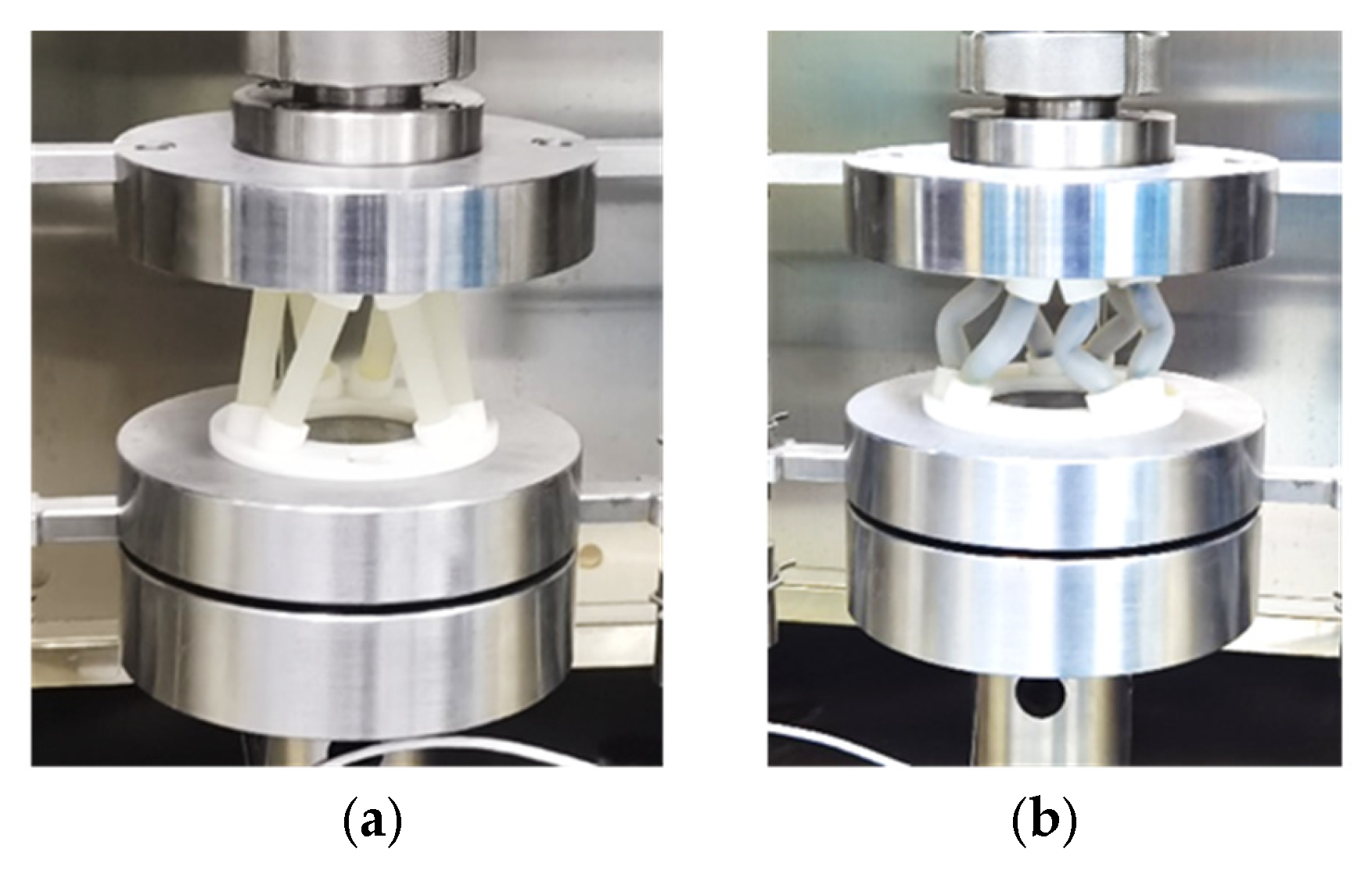
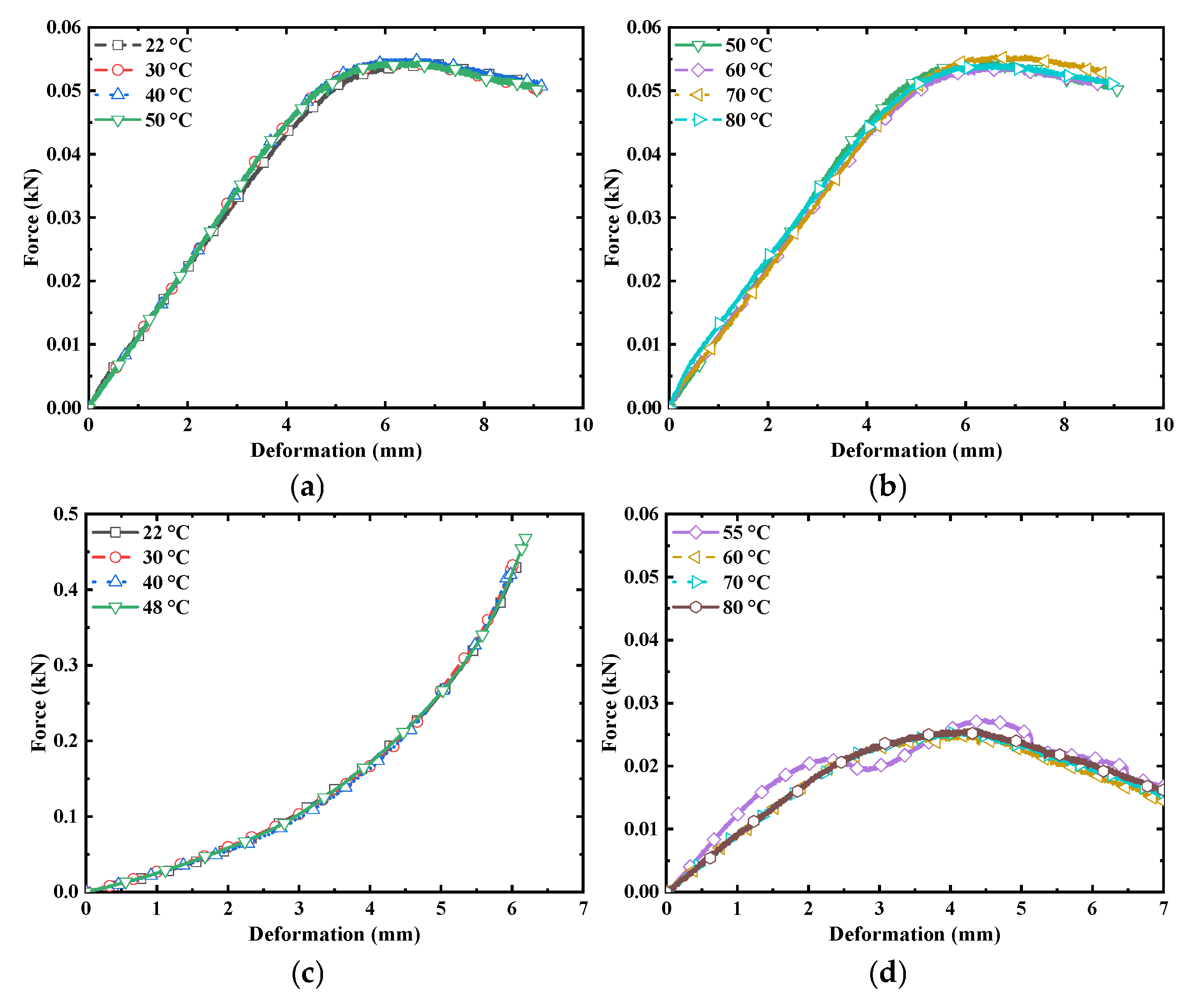
4.2. Compression Testing of the Stewart Platform

Two different types of Stewart platform composite structures were assembled using the different driving structures described above. They are the silicone-rubber-connected Stewart platform composite structure (SP-Silicon Rubber), and the soft-connected composite Stewart platform composite structure (SP-Composite). The compression testing machine with an environmental chamber was used as the compression test platform. In the test, the loading rate was set as 3 mm/min; the compression test of the platform is shown in Figure 8.
According to [36], the empirical equation of structural stiffness k is obtained as follows:
k = P δ
where P is constant force acting on the structure, and δ denotes the deformation due to force.
The compression force–displacement curves of the platform test are shown in Figure 9. The straight-line segment in the elastic deformation stage provides three measurements and the structural stiffness of the platform is calculated using Equation (5), as shown in Table 5.

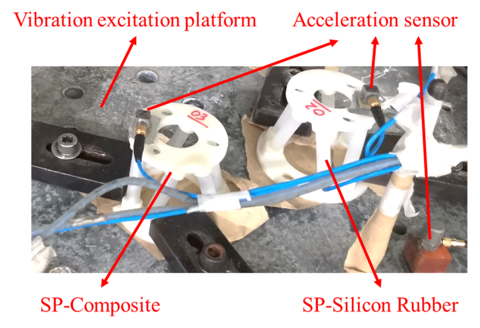
4.3. Vibration Test of the Stewart Platform

It is well known that the vibration-reduction effect of a structure can be changed by changing its structural stiffness [37,38,39]. Therefore, the prepared Stewart platform composite structure was subjected to vibration tests. The vibration tests applied to the platform are shown in Figure 10. During the vibration test, the lower platform is fixed to the vibration table, and the acceleration sensor is installed on the upper platform, without other external loads. Since the mass of the accelerometer is smaller than that of the Stewart platform, the influence of the mass of the accelerometer on the test is ignored.
In the vibration test, the amplitude of the applied sine wave was 0.5 g, the frequency range was 5 Hz to 2000 Hz, and the scanning frequency was 1 oct/min. In order to ensure that the temperature during the test was controllable, a vibration test bench with a constant temperature box was used for the test. The SP-Silicon Rubber and SP-Composite were tested at 25 °C, 60 °C, and 25 °C (25 °C → 60 °C → 25 °C). The resulting curve is shown in Figure 10.
In Figure 11, T on the vertical axis represents the transmissibility of the vibration, and it is calculated as follows:
T = 20 × l o g A 1 A 0
where A 1 is the acceleration value of the upper platform, and A 0 represents the acceleration value of the vibration test.
In Figure 11a–c, the SP-Silicon Rubber vibration curve remains basically unchanged at 25 °C, 60 °C, and 25 °C (25 °C → 60 °C → 25 °C). This is because the properties of the silicone rubber are stable in the environment of −53 °C~232 °C. The natural frequency of the SP-Silicon Rubber was kept stable with the value of 61 Hz. After 108 Hz, the transmission rate is below 0 db. The results show that SP-Silicon Rubber has a vibration isolation effect when the vibration frequency is greater than 108 Hz.
As shown in Figure 11d, temperature-induced stiffness modulation can enable the SP-Composite to achieve a resonance frequency shift of 76.1 Hz (120.5 Hz at 25 °C → 44.4 Hz at 60 °C). However, the effective vibration isolation frequency range can be widened by 31.6 Hz when the vibration frequency is greater than 88.9 Hz at 60 °C. This outperforms the 25 Hz bandwidth expansion reported in electromagnetic negative-stiffness Stewart platforms [18], demonstrating the superiority of LMPA-based phase-change control.
Comparing the SP-Composite, the difference between the test result curve at 60 °C and 25 °C is larger, and at 25 °C (25 °C → 60 °C → 25 °C) and 25 °C it is much smaller, as shown in Figure 11. The reason for this is that, during the process of temperature recovery from 60.0 °C to 25.0 °C, LMPA experienced a secondary cooling phenomenon, resulting in a hysteresis effect in the vibration test curve at 25 °C (25 °C → 60 °C → 25 °C). Comparing Figure 12, it can be seen that, compared with the initially prepared LMPA, under the action of gravity, the upper end of the LMPA after secondary cooling becomes sparse, and defects appear in the upper part, as shown in the darker colored part of the upper end in Figure 12b; meanwhile, the lower end becomes denser and denser, as shown in the lower part of Figure 12b. Compared with the initial LMPA state, the structure of LMPA in the variable-stiffness driving column changes after secondary cooling, resulting in a lag effect between the 25 °C (25 °C → 60 °C → 25 °C) test results and the room temperature (25.0 °C) test results.

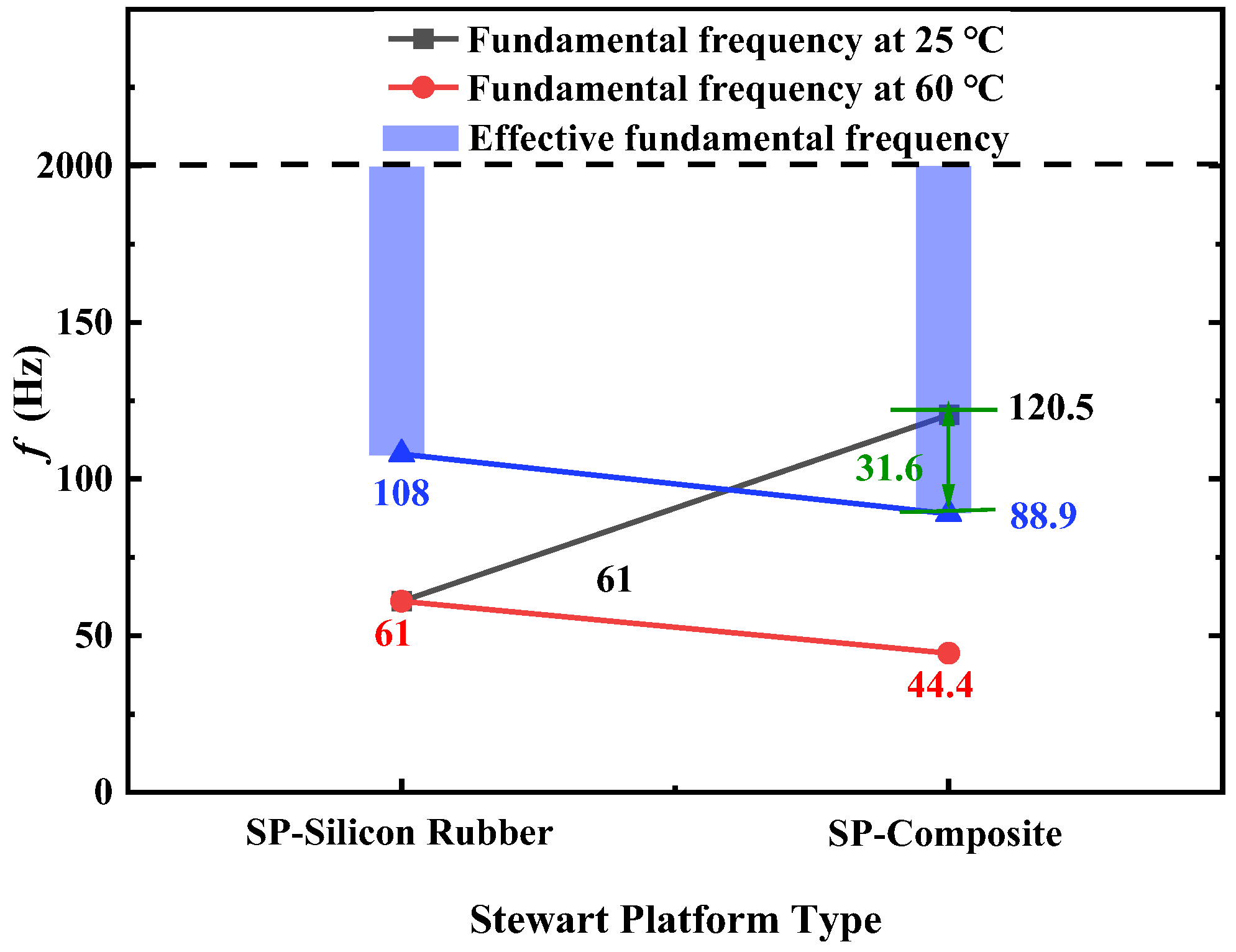
4.4. Results and Discussion

Among the platforms, the change in the structural stiffness of the SP-Composite is the largest at 22 °C and 60 °C. The structural stiffness of the SP-Composite is changed to 4 times, as shown in Figure 13. The compressive modulus of the driving column changes significantly with the phase transition of the LMPA, which further results in a change in the structural stiffness of the entire Stewart platform composite structure. The structural stiffness of SP-Silicon Rubber remains unchanged due to the stability of the silicone rubber material at 22 °C and 60 °C. The results show that the structural stiffness of the Stewart platform composite structure vary with the compressive modulus of the driving columns. This is also consistent with the findings presented in the second section, whereby the natural frequency of the structure can change with the stiffness of the structure; this can broaden the natural frequency range of the structure, thereby achieving vibration isolation and isolation functions.
Table 6 presents the performance indicators of different platforms at different temperatures. From Table 6 and Figure 14, temperature-induced stiffness modulation enabled a resonance frequency shift of 76.1 Hz (120.5 Hz at 25 °C t 44.4 Hz at 60 °C), and the effective vibration isolation frequency range can be widened by 31.6 Hz; the structural stiffness of the SP-Composite showed a fourfold increase. These results show that the vibration effect of these Stewart platform composite structures changes with their stiffness. However, the change in the stiffness effect of these Stewart platform composite structures is caused by the phase transition of the LMPA at different temperatures. Therefore, it is possible to design and manufacture a Stewart platform composite structure, which is more suitable for low frequency and broadband frequency by making good use of the vibration characteristics of the platform caused by variable stiffness.

5. Conclusions

Drawing on the idea that variable stiffness can alter the natural frequency of a structure, a novel Stewart platform incorporating LMPA with temperature-responsive phase-transition properties was engineered. This innovative design features adjustable stiffness and vibration-damping capabilities, tailored for mitigating micro-vibrations during the routine operations of spacecrafts. The dynamic stiffness and damping behavior of the platform were validated via an experimental analysis of its mechanical and vibrational properties. The key findings are outlined below:
(1)
A mathematical model for a variable-stiffness Stewart vibration isolation structure was developed, addressing the specific requirements for the isolation of micro-vibrations in spacecraft. We also assessed the impact of the drive column stiffness on the vertical Stewart platform’s axial transmission rate. The study reveals that, as the stiffness coefficient of the drive columns increases, there is a corresponding rise in both the vibration response transmission rate and the resonant frequency of the vertical Stewart platform.
(2)
The innovative Stewart damping structure’s stiffness is responsive to changes in temperature. Notably, the stiffness of the SP-Composite at 25 °C can be 5.4 times greater than at 60 °C.
(3)
The Stewart platform’s novel composite structure enables the broadening of the effective vibration isolation frequency range with temperature variations. Specifically, the SP-Composite’s effective damping frequency range can be extended by 31.6 Hz, from 88.9 Hz to 120.5 Hz, achieving up to a 10 dB attenuation in vibrations. The expanded effective isolation band (88.9–120.5 Hz) covers 78% of the critical disturbance frequencies from momentum wheels (50–200 Hz), demonstrating significant engineering applicability.
In conclusion, this study provides a reference for the exploration of new theories and technologies for micro-vibration suppression in the aerospace field. It also provides methods for vibration reduction and isolation, which can push the development of spacecraft towards miniaturization and integration. Conducting research on the response characteristics of the LMPA variable-stiffness Stewart platform has high engineering application value.

Author Contributions

Conceptualization, Z.H. and L.Z.; methodology, Z.H.; software, Z.H.; validation, Z.H., Z.L. (Zongnan Liu) and Z.S.; formal analysis, Z.H.; investigation, Z.H.; resources, Z.S.; data curation, Z.H. and Z.L. (Zhenyu Liu); writing—original draft preparation, Z.H. and Z.L. (Zhenyu Liu); writing—review and editing, Z.H.; visualization, Z.S.; supervision, Z.H. and Z.S.; project administration, Z.L. (Zongnan Liu) and Z.S. All authors have read and agreed to the published version of the manuscript.

Funding

This research received no external funding.

Data Availability Statement

The data used to support the findings of this study are included in the article.

Conflicts of Interest

The authors declare no conflicts of interest.

References

  1. Wang, Y.; Sun, H.; Hou, L. Event-triggered anti-disturbance attitude and vibration control for T-S fuzzy flexible spacecraft model with multiple disturbances. Aerosp. Sci. Technol. 2021, 117, 106953. [Google Scholar] [CrossRef]
  2. Liu, Z.; Han, Z.; Zhao, Z.; He, W. Modeling and adaptive control for a spatial flexible spacecraft with unknown actuator failures. Sci. China Inf. Sci. 2021, 64, 152201. [Google Scholar] [CrossRef]
  3. Zhang, J.; Han, Z.; Liu, Y.; Sun, S. Modal characteristics and manufacturing method of variable stiffness facesheets of sandwich plates made by robotic fiber placement. Compos. Struct. 2021, 270, 114065. [Google Scholar] [CrossRef]
  4. Yan, G.; Zou, H.X.; Yan, H.; Tan, T.; Wang, S.; Zhang, W.-M.; Peng, Z.-K.; Meng, G. Multi-direction vibration isolator for momentum wheel assemblies. J. Vib. Acoust. 2020, 142, 041007. [Google Scholar] [CrossRef]
  5. Liu, C.; Jing, X.; Daley, S.; Li, F. Recent advances in micro-vibration isolation. Mech. Syst. Signal Process. 2015, 56, 55–80. [Google Scholar] [CrossRef]
  6. He, Z.; Feng, X.; Zhu, Y.; Yu, Z.; Li, Z.; Zhang, Y.; Wang, Y.; Wang, P.; Zhao, L. Progress of Stewart vibration platform in aerospace micro–vibration control. Aerospace 2022, 9, 324. [Google Scholar] [CrossRef]
  7. Li, L.; Wang, L.; Yuan, L.; Zheng, R.; Wu, Y.; Sui, J.; Zhong, J. Micro-vibration suppression methods and key technologies for high-precision space optical instruments. Acta Astronaut. 2021, 180, 417–428. [Google Scholar] [CrossRef]
  8. Dasgupta, B.; Mruthyunjaya, T.S. The Stewart platform manipulator: A review. Mech. Mach. Theory 2000, 35, 15–40. [Google Scholar] [CrossRef]
  9. Haynes, L.S. Six Degree of Freedom Active Vibration Damping for Space Applications; NASA: Washington, DC, USA, 1993. [Google Scholar]
  10. Cheng, J.; Cheng, W.; Li, X. Modeling and simulation of the disturbance torque generated by solar array drive assembly. J. Vib. Shock 2017, 36, 188–194. [Google Scholar]
  11. Wen, S.; Jing, J.; Cui, D.; Wu, Z.; Liu, W.; Li, F. Vibration isolation of a double-layered Stewart platform with local oscillators. Mech. Adv. Mater. Struct. 2021, 29, 6685–6693. [Google Scholar] [CrossRef]
  12. Furqan, M.; Suhaib, M.; Ahmad, N. Studies on Stewart platform manipulator: A review. J. Mech. Sci. Technol. 2017, 31, 4459–4470. [Google Scholar] [CrossRef]
  13. Tsushima, N.; Hayashi, Y.; Yokozeki, T. Dispersion analysis of plane wave propagation in lattice-based mechanical metamaterial for vibration suppression. Aerospace 2024, 11, 637. [Google Scholar] [CrossRef]
  14. Liu, L.; Zheng, G.; Huang, W. Octo-strut vibration isolation platform and its application to whole spacecraft vibration isolation. J. Sound Vib. 2006, 289, 726–744. [Google Scholar] [CrossRef]
  15. Boltosi, A.; Chiriac, A.; Nagy, R.; Bereteu, L. Stewart platform: Application of smart fluid dampers in this field. Ann. Univ. Oradea Fascicle Manag. Technol. Eng. 2008, 7, 1–6. [Google Scholar]
  16. Zheng, Y.; Li, Q.; Yan, B.; Luo, Y.; Zhang, X. A Stewart isolator with high-static-low-dynamic stiffness struts based on negative stiffness magnetic springs. J. Sound Vib. 2018, 422, 390–408. [Google Scholar] [CrossRef]
  17. Wang, C.; Xie, X.; Chen, Y.; Zhang, Z. Investigation on active vibration isolation of a Stewart platform with piezoelectric actuators. J. Sound Vib. 2016, 383, 1–19. [Google Scholar] [CrossRef]
  18. Wu, Z.; Jing, X.; Sun, B.; Li, F. A 6-DOF passive vibration isolator using X-shape supporting structures. J. Sound Vib. 2016, 380, 90–111. [Google Scholar] [CrossRef]
  19. Wang, M.; Hu, Y.; Sun, Y.; Ding, J.; Pu, H.; Yuan, S.; Zhao, J.; Peng, Y.; Xie, S.; Luo, J. An adjustable low-frequency vibration isolation Stewart platform based on electromagnetic negative stiffness. Int. J. Mech. Sci. 2020, 181, 105714. [Google Scholar] [CrossRef]
  20. Yang, X.; Wu, H.; Chen, B.; Kang, S.; Cheng, S. Dynamic modeling and decoupled control of a flexible Stewart platform for vibration isolation. J. Sound Vib. 2019, 439, 398–412. [Google Scholar] [CrossRef]
  21. Zhu, D.; Zhan, W. Topology optimization of a 6-DOF spatial compliant mechanism based on Stewart prototype platform. Acta Mech. Sin. 2019, 35, 1044–1059. [Google Scholar] [CrossRef]
  22. Jiang, M.; Rui, X.; Zhu, W.; Yang, F.; Zhang, Y. Optimal design of 6-DOF vibration isolation platform based on transfer matrix method for multibody systems. Acta Mech. Sin. 2021, 37, 127–137. [Google Scholar] [CrossRef]
  23. Tang, Y.; Liu, X.; Cai, G.; Liu, X. Active vibration control of a large space telescope truss based on unilateral saturated cable actuators. Acta Mech. Sin. 2022, 38, 522040. [Google Scholar] [CrossRef]
  24. Seymour, E. Liquid Metals. Nature 1973, 242, 540. [Google Scholar] [CrossRef]
  25. Buckner, T.; Yuen, M.; Kim, S.; Kramer-Bottiglio, R. Enhanced variable stiffness and variable stretchability enabled by phase-changing particulate additives. Adv. Funct. Mater. 2019, 29, 1903368. [Google Scholar] [CrossRef]
  26. Piskarev, E.; Shintake, J.; Ramachandran, V.; Baugh, N.; Dickey, M.D.; Floreano, D.; Piskarev, E. Lighter and stronger: Cofabricated electrodes and variable stiffness elements in dielectric actuators. Adv. Intell. Syst. 2020, 2, 2000069. [Google Scholar] [CrossRef]
  27. Hoang, T.T.; Quek, J.J.S.; Thai, M.T.; Phan, P.T.; Lovell, N.H.; Do, T.N. Soft robotic fabric gripper with gecko adhesion and variable stiffness. Sens. Actuators A Phys. 2021, 323, 112673. [Google Scholar] [CrossRef]
  28. Zhang, Z.; Wu, Z.; Luo, X.; Liu, W. Numerical study on convective heat transfer of liquid metal gallium in turbine guide vane. Aerospace 2023, 10, 548. [Google Scholar] [CrossRef]
  29. Liu, J.; Li, Z.; Yu, Y.; Wang, P. 3D-Printed polymer composites based upon low melting point alloys filled into polylactic acid. J. Phys. Conf. Ser. 2021, 2002, 5. [Google Scholar] [CrossRef]
  30. Liu, Y.; Matsuhisa, H.; Utsuno, H. Semi-active vibration isolation system with variable stiffness and damping control. J. Sound Vib. 2008, 313, 16–28. [Google Scholar] [CrossRef]
  31. Dong, X.-J.; Peng, Z.-K.; Zhang, W.-M.; Meng, G.; Chu, F.-L. Parametric characteristic of the random vibration response of nonlinear systems. Acta Mech. Sin. 2013, 29, 267–283. [Google Scholar] [CrossRef]
  32. Zuo, X.; Zhang, W.; Chen, Y.; Oliveira, J.; Zeng, Z.; Li, Y.; Luo, Z.; Ao, S. Wire-based directed energy deposition of NiTiTa shape memory alloys: Microstructure, phase transformation, electrochemistry, X-ray visibility and mechanical properties. Addit. Manuf. 2022, 59, 103115. [Google Scholar] [CrossRef]
  33. Hao, Y.; Gao, J.; Lv, Y.; Liu, J. Low melting point alloys enabled stiffness tunable advanced materials. Adv. Funct. Mater. 2022, 32, 2201942. [Google Scholar] [CrossRef]
  34. Marechal, L.; Balland, P.; Lindenroth, L.; Petrou, F.; Kontovounisios, C.; Bello, F. Toward a common framework and database of materials for soft robotics. Soft Robot. 2021, 8, 284–297. [Google Scholar] [CrossRef]
  35. Segers, J.; Hedayatrasa, S.; Verboven, E.; Poelman, G.; Van Paepegem, W.; Kersemans, M. Efficient automated extraction of local defect resonance parameters in fiber reinforced polymers using data compression and iterative amplitude thresholding. J. Sound Vib. 2019, 463, 114958. [Google Scholar] [CrossRef]
  36. Jiang, L.; Xiao, S.; Yang, B.; Yang, G.; Zhu, T.; Wang, M. Bimodulus constitutive relation and mesoscopic model of braided composites. Compos. Struct. 2021, 270, 114115. [Google Scholar] [CrossRef]
  37. Labans, E.; Bisagni, C. Buckling and free vibration study of variable and constant-stiffness cylindrical shells. Compos. Struct. 2019, 210, 446–457. [Google Scholar] [CrossRef]
  38. Lim, C.; Yaw, Z.; Chen, Z. Periodic and aperiodic 3-D composite metastructures with ultrawide bandgap for vibration and noise control. Compos. Struct. 2022, 287, 115324. [Google Scholar] [CrossRef]
  39. Kim, H.-G.; Kwon, S.-C.; Koo, K.-R.; Song, S.-C.; Yu, Y.; Song, Y.; Park, Y.-H.; Oh, H.-U. Performance investigation of superplastic shape memory alloy-based vibration isolator for X-band active small SAR satellite of S-STEP under acoustic and random vibration environments. Aerospace 2022, 9, 642. [Google Scholar] [CrossRef]
Figure 1. Vibration system with a single degree of freedom.
Aerospace 12 00279 g001
Figure 2. Variation in the force transmission rate with the excitation force frequency at different stiffness levels.
Aerospace 12 00279 g002
Figure 3. Effect of the stiffness coefficient of the driving column on vibration isolation characteristics of variable stiffness Stewart platform.
Aerospace 12 00279 g003
Figure 4. Preparation process for the test samples.
Aerospace 12 00279 g004
Figure 5. Schematic of the driving column. (a) C-LMPA. (b) DS-Composite. (c) DS-Silicon Rubber.
Aerospace 12 00279 g005
Figure 6. Partial driving column test process at different compression temperatures: (a) 22 °C. (b) 60 °C.
Aerospace 12 00279 g006
Figure 7. Compressive force–displacement curves of different driving columns at different temperatures. (a) All test result curves. (b) Partial test result curve.
Aerospace 12 00279 g007
Figure 8. Compression test of the platform for different Stewart platform composite structures. (a) SP-Silicon Rubber. (b) SP-Composite.
Aerospace 12 00279 g008
Figure 9. Compression force–displacement curves of the different platforms. (a) Test results of SP-Silicon Rubber at 22~50 °C. (b) Test results of SP-Silicon Rubber at 50~80 °C. (c) Test results of SP-Composite at 22~55 °C. (d) Test results of SP-Composite at 55~80 °C.
Aerospace 12 00279 g009
Figure 10. The vibration tests of the platform for different Stewart platform composite structures.
Aerospace 12 00279 g010
Figure 11. Vibration test of the different platforms at different temperatures. (a) At 25 °C. (b) At 60 °C. (c) Return to 25 °C. (d) Comparison of SP-Composite at different temperatures.
Aerospace 12 00279 g011
Figure 12. Photograph of the LMPA after secondary cooling. (a) Initial LMPA state. (b) LMPA status after secondary cooling.
Aerospace 12 00279 g012
Figure 13. Structural stiffness of the different platforms at different test temperatures.
Aerospace 12 00279 g013
Figure 14. Vibration isolation effect of different platforms at different temperatures.
Aerospace 12 00279 g014
Table 1. Performance parameters of the manufacturing materials.
NumberTypeDensity (kg/m3)Elastic Modulus (MPa)Poisson’s Ratio
01LMPA–Solid9.5 × 1033000.0~15,000.00.33
02LMPA–Liquid9.5 × 1030.001~0.1-
03Dragon Skin 302.68 × 1030.1~1.00.45
Table 2. Structural parameters of the drive column.
NumberType L 0 (mm) D 0 (mm)
01C-LMPA50.05.0
02DS-Composite50.010.0
03DS-Silicon Rubber50.010.0
Table 3. Experimental details for the compressive test of different driving columns.
NumberType T 1 (°C) L 1 (mm) D 1 (mm)
01C-LMPA22.010.05.0
02DS-Silicon Rubber22.012.810.0
03DS-Silicon Rubber60.010.99.8
04DS-Composite22.049.510.0
05DS-Composite60.050.410.1
Table 4. Compressive modulus of different types of driving columns at different test temperatures.
NumberType T 1 (°C)Modulus (MPa)Standard Deviations
01C-LMPA22.03795.40.36
02DS-Silicon Rubber22.01.10.21
03DS-Silicon Rubber60.01.10.22
04DS-Composite-Soft22.09.40.18
05DS-Composite-Soft60.00.80.14
Table 5. Structural stiffness of different types of platform at different test temperatures.
NumberTypeStructural Stiffness at 22 °C (N/m)Standard
Deviations
Structural Stiffness at 60 °C (N/m)Standard
Deviations
01SP-Silicon Rubber10,6000.2910,6000.32
02SP-Composite30,4000.3679300.21
Table 6. Performance indicators of different platforms at different temperatures.
NumberTypeIsolation RangeResonant Frequency ShiftStructural
Stiffness Ratio
01SP-Silicon Rubber-61.0 Hz → 61.0 Hz1.0
02SP-Composite88.9 Hz~120.5 Hz44.4 Hz → 120.5 Hz4.0
Disclaimer/Publisher’s Note: The statements, opinions and data contained in all publications are solely those of the individual author(s) and contributor(s) and not of MDPI and/or the editor(s). MDPI and/or the editor(s) disclaim responsibility for any injury to people or property resulting from any ideas, methods, instructions or products referred to in the content.

