Article

Functionalization of Adhesive Bonding to Control On-Demand Disassembly of Composite Aeronautical Structures

by
Lorraine Aparecida Silva
1,
Christine Espinosa
1,*,
Rémy Chieragatti
1,
Eric Paroissien
1,
Frédéric Lachaud
1 and
Lucas Filipe Martins da Silva
2
1
Institut Clément Ader (ICA), Université de Toulouse, CNRS, ISAE-SUPAERO, UPS, INSA, IMT Mines Albi, 3 rue Caroline Aigle, 31400 Toulouse, France
2
Department of Mechanical Engineering, University of Porto, 4200-465 Porto, Portugal
*
Author to whom correspondence should be addressed.
Aerospace 2025, 12(4), 269; https://doi.org/10.3390/aerospace12040269
Submission received: 23 January 2025 / Revised: 10 March 2025 / Accepted: 11 March 2025 / Published: 22 March 2025

Abstract

:
In the context of enhancing the sustainability of aerospace vehicles, the structures must be designed to anticipate the possibility of disassembly. Mandatory certification in aeronautics and the robustness of satellites require structures to maintain their integrity to ensure safety during their life, which can come into conflict with the need for disassembling or demising. This is particularly the case for composite structures assembled though adhesive bonding. In this paper, a controlled disassembly device of the substrates of a component for keeping their integrity and surface states after debonding is proposed. The addition of thermally expandable particles (TEPs) and a metallic grid is investigated in various proportions, substrates, and adhesives. It is shown that the introduction of the disassembling system into a 100 µm adhesive bonding does not significantly affect the strength of the joint during life. Disassembly only happens when and if desired at a load level above the natural mode I and mode II ruptures of the assembly. The proposed solution helps to make functionalization of the bonded joint a good way to address sustainability regarding the preservation of resources, transforming the adhesive joint into a structural functional material.

1. Introduction

Evaluating the possibility of controlling the disassembly of the structural components of composite aeronautical structures has become a crucial issue for sustainability in aeronautics and space (End-of-life Reusing, recycling, rethinking|Airbus accessed on 10 March 2025). It is not only a question of business but also of considering environmental aspects [1]. While disassembly on demand (DoD) is increasingly considered in the automotive industry, it may conflict with the certification requirements of aeronautical structural integrity and robustness for in-service life. This is particularly the case for adhesively bonded components, where bonding must maintain structural integrity throughout their service life. This can concern internal components like seats or cabin equipment, which represent a new market (https://www.aira-international.com/recyclingaircraftinteriors/ accessed on 10 March 2025), or larger structural components in different sections of a plane (Figure 1). The growing use of complex vehicles and materials makes design for demise (D4D) a proactive opportunity to reuse elementary materials or components rather than just recycling them by burning them to produce heat. However, one of the best-known problems with assembly by adhesive joints is the difficulty in dismantling the components without damaging them. It is then necessary to find a way to control debonding only when desired, keeping structural integrity and load-bearing capability during in-service life without adding mass.
The manufacture of bonded joints is a multi-physical process consisting of several stages that determine the properties of the resulting assembled component. Several parameters related to the characteristics of the material and the environment come into play. Assuming that the nature of the substrates is prescribed, the first step is the choice of adhesive, which includes defining the surface preparation, the deposition, the conditions for bringing the substrates together that will condition the spread of the adhesive, and the polymerization process with the substrates in place [3]. The docking conditions, in particular the speed or angle of approach, or the pressure applied, are important for the final properties of the joint and are also responsible for the distribution and final thickness of the adhesive [4].
Different ways exist to disassemble structures. A good review is given in [5]. For the sake of simplicity, not all the methods are discussed in this paper. A new interesting technique is based on laser shocks [6,7,8]. Debonding is indeed produced by spalling. As for other techniques, this method presents some drawbacks. Since the crack initiation is based on the reflection of a shock wave propagating in the thickness from the outer surface, one main limitation is that it necessitates having flat structures. Furthermore, to force debonding at the chosen depth location depth and set the shock intensity and duration, it is necessary to know the impedance of each layer in the depth, which is not easy for complex structures or materials. Instead of acting from the outside, our study focuses on functionalization of the joint itself. The functionalization of adhesive joints has been the subject of several studies in recent years. Following Marques et al. [9], there are essentially three main strategies: combining several adhesives [10], introducing gradients of polymerization [11], or using additives. Among the existing methodologies available on the market or in development at low TRLs in scientific laboratories, using thermally expandable particles (TEPs) as additives is an interesting demounting strategy (Figure 2) without making significant modifications to the structure or assembly process [5,6,7,8,9,10,11,12]. TEPs can stay inactive in a structure for its entire life cycle. When disassembly time has come, TEPs can be activated through heating [5,11,13]. TEPs can swell up and reach 60 times their initial volume when heated. Internal pressure is created, creating hollow and stretched zones in the adhesive. It is then easy to unbind the two substrates by applying a tensile or shear load. Designed in this way, the particle-filled adhesive joint provides the two main dual functions required: load-bearing capability and mechanical resistance during service life and dismantling for repair or recycling at the end of its life.
Our study is focused on fabrication, verification of load sustainability, and demonstration of disassembly control, which are three of the four main steps in the life cycle of a product, as presented in Figure 3.
To verify load sustainability and evaluate the possibility of controlling disassembly when we want and only if we want multi-material structures regardless of the materials, we have fabricated dedicated DCB and SLJ samples. But before that step, we wanted to evaluate the influence of inserting TEPs into a liquid two-phase adhesive at different mass percentages on the spread of the adhesive during contact between the two substrates. Because it is commonly used in the aerospace sector [16], we have chosen 3MTM EC2216. The final thickness and the adequate spreading or placement of the adhesive are indeed two major factors of the joint load-bearing capability [4,17]. For that purpose, we have developed a special experimental device that gives us the measured contact force during compression of the adhesive joint and simultaneously allows us to visualize the adhesive spreading with two different angles of view. This device has been used with complex shapes of substrates. This paper presents only pictures of NOMEX honeycombs and metallic meshes following their impregnation. In the second stage, tension tests up to failure were conducted to understand the rupturing process for different mass percentages of TEPs. Variability analysis is presented and analyzed. Finally, mode I (tensile opening) and mode II (axial shear sliding) joint rupture samples were fabricated with adhesives of 100 µm thickness with different impregnation and mass percentages of TEPs. Rupture tests were performed with liquid adhesive and film forms used in aeronautics. It is shown that the ruptures arise only when the TEPs are activated. Even for the worst configuration of TEP distribution in the adhesive, which is the distributed and non-controlled one, it is shown that the rupture can be driven in a cohesive way for low mass percentages. Low mass percentages and the ideal distribution of TEPs do not significantly decrease the load-bearing capability, nor do they significantly increase the global mass of the assembly. This demonstrates the capability of the disassembly system to be activated, when and if desired, for complex or composite substrates without damaging them.

2. Materials and Methods

Since the main objective is to propose a method to control disassembly whatever the materials and dimensions of the substrates composing the assembled structures, the presented work is organized around three major steps: assembly conditions and effect of TEPs on impregnability of complex structures; influence of TEPs on load-bearing capability of massive materials; influence of the TEPs and their trigger on the load-bearing capability of the assembled structures. The particles used in this paper were provided courtesy of the company Nouryon (Specialty Chemicals B.V., Amsterdam, The Netherlands) under reference Expancel 031 DU 40. Their activation temperature is 80 °C.

2.1. Materials Mixing and Joint Assembly Processes

The EC2216 liquid epoxy adhesive and the desired amount of TEP volume are mixed by hand in a cleaned and neutral mixing container. The quantity of each ingredient depends on the final volume of adhesive that is desired and on the chosen volume proportion. For example, 10,000 volumes of adhesive for 15 volumes of TEPS written 10,000:15 in the paper. Then the mixture is poured into a surgical syringe for deposition and spreading analysis (Figure 4). Volume indications on the Figure 4 are not representative of the mixture proportions nor quantities. The syringe is inclined during filling to prevent air entrapment. The level of adhesive is measured to make sure the deposited volume in the final joint is 5 mL for the compression and spreading tests. A series of 3 to 5 samples was fabricated for each configuration of test.
Following the works of Spangenberg et al. [17], a special device was developed to observe the adhesive spreading and simultaneously measure the resistant compression force when two substrates are brought together to create a welded joined structure.
Figure 5 below presents two cases. In the first case, a metallic mesh is simply placed above the bottom substrate and maintained at each end by tape (left picture). The adhesive is deposited onto the metallic mesh and then squeezed by the upper plate fixed to the mobile crossbar. This case aims at verifying the permeability of the mesh and its impregnation capacity. In the second case, the adhesive is deposited onto a Plexiglass-bottom plate, and a NOMEX honeycomb maintained in contact with the upper Plexiglas plate through tape at its extremities moves down to the desired thickness of the joint, squeezing the deposited adhesive.
The bottom plexiglass plate on which the adhesive is deposited is 100 mm × 150 mm. The upper plate that moves down at a prescribed velocity “V” (green arrow on Figure 6) to squeeze the adhesive is 30 mm × 150 mm. Because the upper plate is smaller in width, the adhesive flows outside its lateral boundaries when squeezed. The shape of the outer flow depends on the viscosity of the adhesive and on the contact forces with the plexiglass. The evolution of the shape is registered as a function of time, as shown in Figure 6.
The resistance force plotted on ordinate axis of Figure 6 is registered using a 10 kN force cell mounted on the mobile crossbar of the INSTRON 5969 device from Instron France S.A.S. Elancourt France, Élancourt, France (Red circle on Figure 6 show the location of the cell force). Two 100 µm-thick aluminum shims are placed at the extremities of the bottom plexiglass plate to set the final thickness of the joint. When the upper plate touches the shims, the force suddenly increases and represents the aluminum compression resistance. The maximum force of adhesive joint setting is measured at the slope change on the force–displacement curve. The displacement is measured from the initial position of the upper plate above the adhesive joint just after the adhesive deposition to limit the adhesive flow due to gravity. The maximum displacement is different from one experiment to another, depending on the height of the adhesive when the upper plexiglass plate touches the adhesive, creating zero force. Since the volume is controlled to always be 5 mL, the height evolves differently depending on the ability of the adhesive to flow with gravity without adding any compression force. The maximum force and maximum displacement are determined by the abscissa and ordinate of the intersection point where there is a sudden slope change due to contact with the shims (big black dots on Figure 6).

2.2. TEP-Enriched Samples for Load Bearing Capability

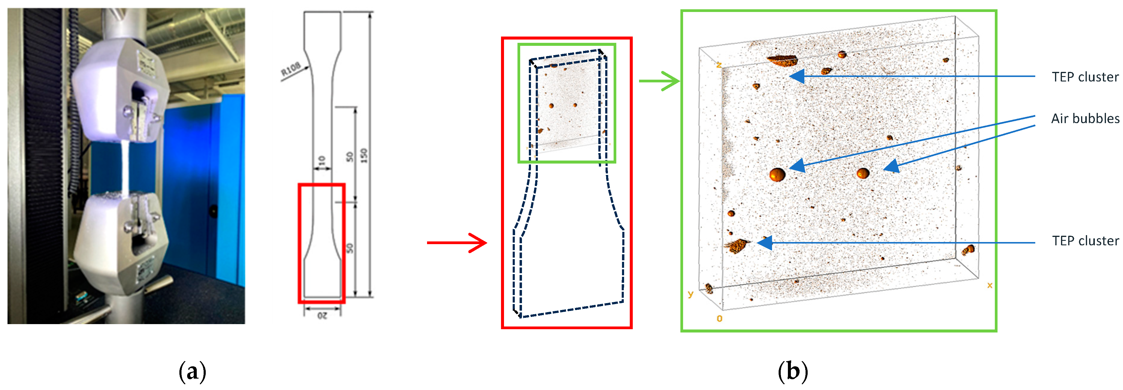
Series of 20 to 30 tensile test samples was fabricated with each of the ratios of 0%/0.15%/0.3% of TEPs to evaluate the influence of the presence of TEPs on the load-bearing capability. The tensile samples’ dimensions and experimental setup are described in Figure 7. This high number of samples was chosen for sensitivity analysis. Indeed, it is well known that the EC2216 epoxy adhesive’s mechanical properties depend on ambient test conditions. Furthermore, the mixing procedure created a non-uniform distribution of TEPs in the volume, and even some air bubbles, as can be observed in Figure 7b. Both are considered critical defaults capable of initiating the rupture and/or propagating it.
The ultimate tensile strength for each percentage of TEPs is reported as a function of axial strain in Figure 8a, and the envelope helps with obtaining the probability density of the Weibull distribution, as shown in Figure 8b.
In order to control the disassembly, the use of clusters of TEPs and a trigger system to initiate the crack, only if desired, is evaluated in the next paragraph.

2.3. Adhesive Joint Samples and Set-Up Preparation for Dissasembly on Demand Testing

To achieve the dual functions for the adhesive joint of load-bearing capability during life and controlled disassembly at the end of life, it is first necessary to evaluate the load-bearing capability of the joint in absence of TEPs or disassembly trigger or both. Three types of tests were performed: tensile opening mode I tests to characterize the joint behavior, tensile opening mode I tests to set and verify disassembly control and shear mode II tests to verify the possibility of using different adhesives with the TEPs and their trigger.
The trigger that was chosen was a metallic mesh so that it was not necessary to use the substrates to heat the TEPs, as can be found in the literature. In our work, substrates can then be metallic, composite, or honeycombs, etc. In these proof-of-concept tests, metallic substrates are used for tensile mode I openings, and both metallic and composite substrates are used for shear mode II ones. The metallic mesh of Gantois Industries Cie based in Saint-Dié-des-Vosges in France under reference n° 437.43 used to trigger the TEPs is made of woven inox 304 L wires of 0.025 mm diameter. The porosity is 37%, and the lateral size of the square aperture is 0.038 mm, allowing good impregnation of the adhesive even with TEPs, as described previously. This mesh was chosen in the Gantois catalogue because it has some characteristics we were seeking, among them being Joule heating capabilities, low thickness, and permeability leading to good impregnability. Analytical computations were performed to estimate the current that should be injected into the mesh to reach the ignition temperature in the TEP-charged liquid adhesive around the metallic mesh without destroying the adhesive surrounding the TEPs. Impregnation tests were conducted, and the samples’ moldings were designed to ensure the position of the metallic mesh in the middle of the adhesive’s joint thickness all over the joint surface. This allows for uniform heating from the center of the joint thickness to have a cohesive rupture and to avoid thermal damage to the substrates. It was not possible to measure the temperature reached inside the DCB or the SLJ samples. The temperature distribution is supposed to be uniform in the metallic mesh inside the joint because of precautions that have been taken in the deposition in the mold to ensure uniform and flat geometry.

2.3.1. DCB Mode I Samples and Test Set-Up

Tensile opening tests were conducted using the same INSTRON 5969 machine equipped with a 10 kN load cell as described earlier to pull apart classical double cantilever beam (DCB) specimens.
Sample dimensions are specified in Figure 9a. These specimens are commonly used for testing crack propagation and were prepared with precise geometry to ensure consistency across all experiments. The joint interface between the two steel rigid substrates does not cover their full length to create a pre-crack of 50 mm and simulate carack initiation. The effective joint length for crack propagation is 140 mm. The specimen is composed of the joint and the two assembled substrates. The substrates are sanded and degreased, and finally an additional coat of primer is applied before the adhesive is set, to ensure a cohesive rupture of the joint. The same process was then carried out for all the tests to eliminate this factor of influence from the experimental plan. The final thickness of the joint is ensured through 2 mm-thick shims. Specimens were cured at 2 bars and 66 °C for 140 min, with an added step for raising the temperature from ambient to 66 °C for 25 min and a second step for another 25 min to come back from 66 °C to ambient, following the 3M™ Scotch-Weld™ Epoxy Adhesive EC-2216 B/A Technical Datasheet.
The fixture consists of two U-shaped supports, which are rigidly attached to the lower fixed part and the movable crosshead of the machine. The specimens are connected to the supports via pins that pass through their width. The fixture is mounted on the machine frame using cylindrical grips. The testing system is hyperstatic, requiring loosening of one of the grips to install the specimen. To ensure proper alignment of at least one part, the upper section of the fixture remains permanently mounted on the machine. The specimen is installed first on the upper pin and then on the lower one. To prevent rotation around the pins, small screws (labeled A and B) pass through the thickness of the specimens and are screwed into the support pins.
Figure 9b provides a lateral view of the experimental setup, where A and B indicate the positions of the screws responsible for securing the specimen to each pin. These screws are tightened onto the flat surfaces of the pins.
To verify that the velocity of charge does not significantly affect the results and gives as few variabilities as possible, 5 velocities were used to test the mobile crossarm: 0.01 mm/min, 0.1 mm/min, 1 mm/min, 10 mm/min, and 100 mm/min. Because of those rates, the test duration varied between 0.04 min and 400 min to reach the desired maximum displacement. The influence of the velocity was evaluated only for the adhesive in absence of TEPs and trigger. No change in the fracture surface pattern nor in the slope of the force–displacement curve was observed. For that reason, the maximal velocity of 10 mm/min was kept for the rest of the tests. The tests were performed at an observed ambient room temperature of 24 °C ± 0.2.

2.3.2. DCB Mode I Samples for Dissassembly Tests

The proposed controlled disassembly method is based on two principles: the presence of TEPs and the addition of a conductive element used as a trigger through Joule effect. In our case, the trigger is a stainless-steel wire mesh, which was described earlier. This concept is the subject of a patent registered under the reference WO2023222900.
The adhesive was tested in various configurations: with the adhesive alone, with a high mass percentage of TEPs, with TEPs sprinkled on the metal fabric, and with metal fabric alone. Situations of TEPs and TEP cluster distribution are illustrated in Figure 10. The different TEP cluster distributions were obtained through uniform mixing for the “distributed” situation or no mixing for the “localized” one.
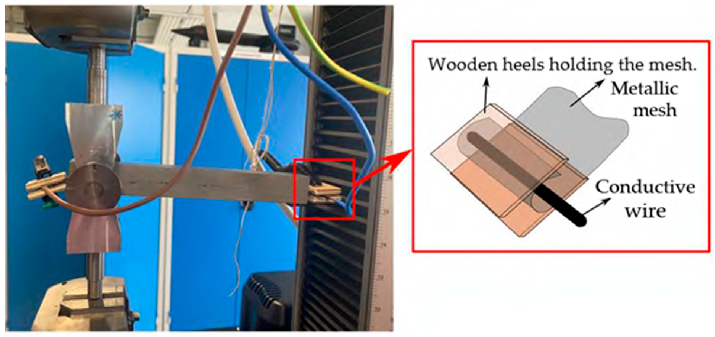
Samples are fabricated following the protocol described in the previous paragraph. When used, the metallic trigger is placed over the adhesive before closing the specimen with the second substrate covering it. The metallic mesh is connected at each extremity to a current generator. The full system is illustrated in Figure 11.
The tests begin by applying a tension at 10 mm/min until reaching a tensile load of 500 N, which is far below the strength of the DCB specimens containing neither TEPs nor trigger. Then, electrical current is injected into the metallic mesh using conductive wires that are wrapped around it, and the time to rupture is measured using a stopwatch. The maximum force and displacements at rupture are also registered.

2.3.3. SLJ Mode II Samples Preparation

The SLJ-type specimens were used for the application and demonstration of the disassembly protocol controlled by the Joule effect for three different adhesives: 3M™ EC2216 Scotch-Weld™ Epoxy Adhesive, Saint Paul, MN, USA (liquid two-component same as previously described), Redux® 609 (film from Hexcel Composites SASU, Blagnac, France), and FM300 (film from Syensqo, Pessac, France). The main difference in the protocol is the application method of the adhesive. For EC2216, the paste adhesive was applied to the substrates using a spatula, as in all previous tests. For the others, patches of adhesive, cut to the size of the bonded area, were applied to the substrates. To be able to use the TEPs and the trigger, three strategies of TEP distribution were tested: no TEPs, TEPs distributed in the whole adhesive (EC2216 liquid only), and TEPs localized in a thin layer of adhesive around the trigger. This last configuration is called “localized”. Wood or silicone shims were fabricated to ensure the desired thicknesses and were placed so that it was possible to assemble all the layers and consider the thickness of the metallic mesh. After assembly, samples were placed in vacuum bags and cured in an oven to polymerize the adhesives. As for DCB samples, the EC2216 followed a cycle of polymerization at 66 °C for 140 min, while the cycle was at 120 °C for 60 min for the Redux®609 and 175 °C for 60 min for the FM®300.
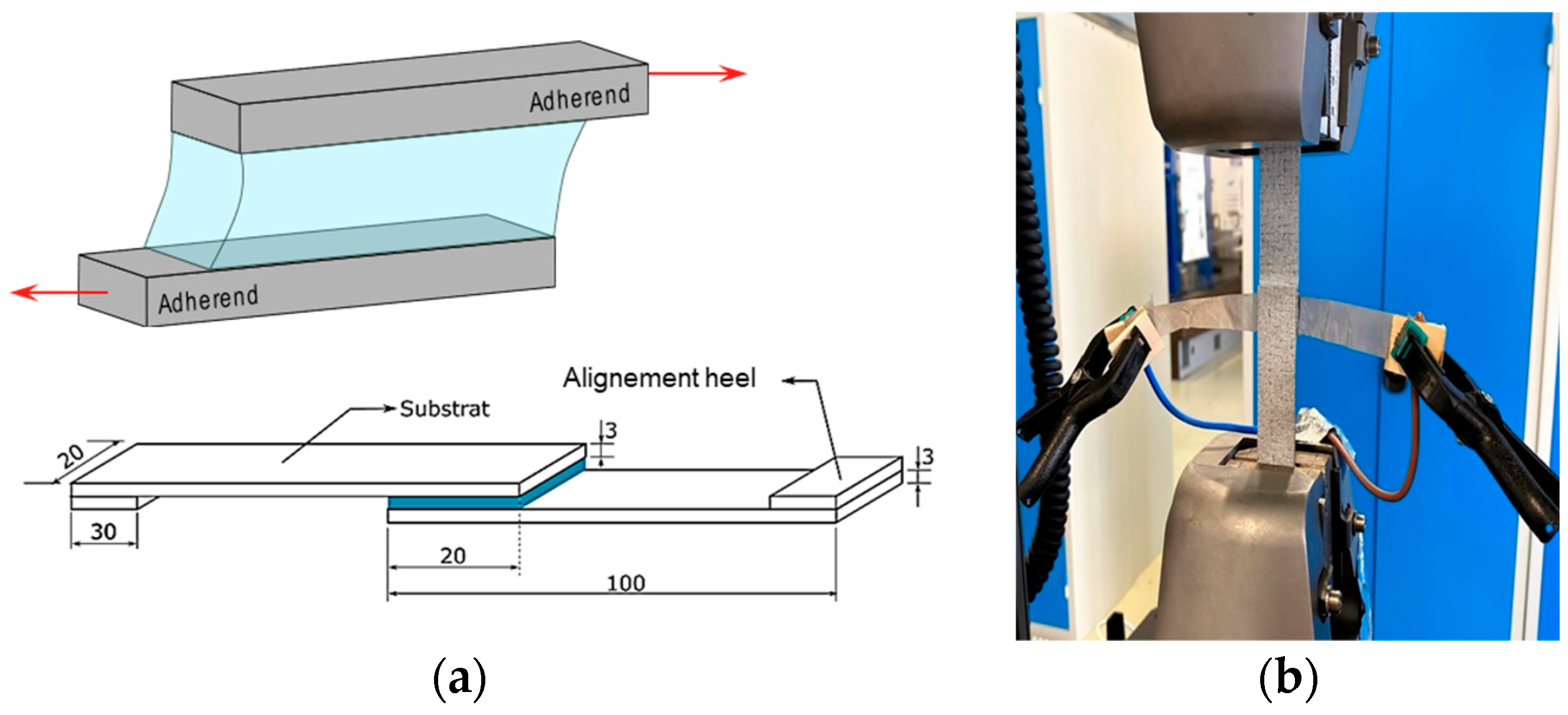
As for the DCB configurations, tests with no TEPs and no metallic mesh were performed to determine the ultimate strength of the “bare” specimens. The geometry of the specimens used can be seen in Figure 12a, and the experimental setup is shown in Figure 12b. The two substrates, as well as the two alignment blocks, were made from carbon fiber composite and epoxy resin, using woven composite plates available in the laboratory from other applications, with their stacking configuration confidential.
To demonstrate the disassembly control of shear samples, a constant force of 500 N was first applied, and the time until failure was measured after beginning injection of the 6A current, following the same procedure as for the DCB disassembly tests.

3. Results and Discussion

3.1. Adhesive Joint Assembly and Adhesive Spreading

It is shown in Figure 6 that the presence of TEPs increases the resistance to compression, but the peak force is delayed in time. This is due to a higher viscosity that limits the effect of gravity and maintains the compact shape of the adhesive longer.
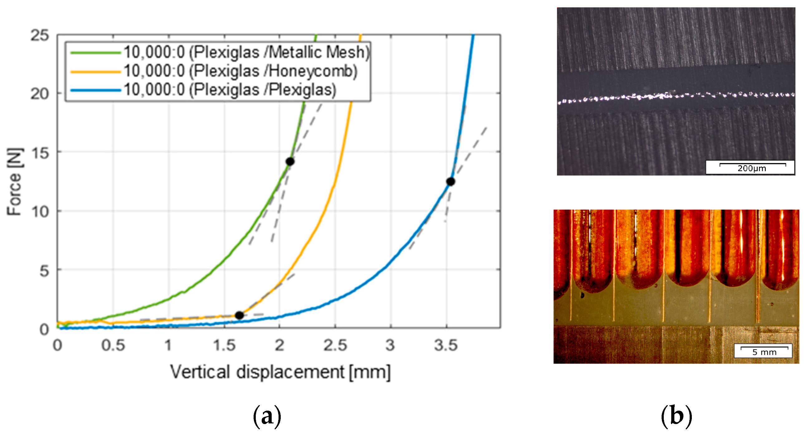
Impregnation test results are illustrated in Figure 13. In the absence of TEPs, the metallic mesh slightly increases the resistance to compression by about 10% compared to the flat plate. The low viscosity helps the liquid adhesive to flow easily in the honeycomb cells, decreasing a lot of the resistance of the axial compression force compared to the flat Plexiglas plate. The final shape of the menisci in the cells illustrates the capillary effect also shown in Figure 6. For the honeycomb case, the maximum displacement is reduced by a factor of two compared to the fat plate. This is because the lateral flow of the adhesive is highly limited by the honeycomb cells. Since the air present in the cells is freely pushed away by the adhesive, the adhesive is not compressed but guided to slide along the NOMEX cell walls.

3.2. TEP-Enriched Adhesive Load Sustainability

As shown in Figure 8, the introduction of TEPs slightly reduces the ultimate strength from 22 MPa to 20 MPa at 0.15% and to 15 MPa at 0.3%. This reduction, as expected, is not significant. The same behavior and variability are observed in all cases. But what is interesting is that the addition of particles narrows the curves. The higher the percentage of TEPs, the smaller the variability in the ultimate tensile strength. This phenomenon may not be solely attributed to the ambient environment of the tests or the percentage of TEP effects. It could correlate with the size and nature of the critical defect responsible for crack initiation as well as the crack propagation rate.
To better understand the regularization effect of the TEPs, the fracture surface was analyzed. Typical fracture patterns are illustrated in Figure 14. It was found that crack initiation and propagation always occur within TEP clusters. Clusters of TEPs are the white ellipsoids in Figure 14a. TEPs in a TEP cluster are visible as black spheres in Figure 14b.
Clusters are also visible in Figure 15. The negligible amount of adhesive in the cluster regions is shown in Figure 15. To understand crack initiation and propagation in the presence of clusters, three types of analysis were performed: volume reconstruction from X-ray data (a), analysis of 2D X-ray images ((a) center), and imaging using SEM ((b), realized by CNES). The crack path is clearly visible between particles strongly trapped in the adhesive and their neighbors in the cluster. The shape of the cluster creates a concentration of stress that initiates the crack.
Building on the findings from various analyses, it was possible to gain insights into the mechanisms of crack initiation and propagation in the presence of clusters and bubbles for the enriched adhesive solely charged by a mechanical load. Understanding this phenomenon is essential for controlling operational modes and ensuring a predictable process. The constraint of “disassembly only if desired when desired” is translated into an engineer innovation form to “find a way to trigger the clusters rupture if desired keeping the RF acceptable and sustain the loads during the life of the structure”.

3.3. Dissassembly on Demand

3.3.1. DCB Mode I Characterization Tests

No change in the fracture surface pattern nor in the slope of the force–displacement curve was observed (see Figure 16). For that reason, the maximal velocity of 10 mm/min was kept for the rest of the tests. The tests were performed at an observed ambient room temperature of 24 °C ± 0.2. Variability of the mm/min speed is due to the 6 h-long duration of the tests that were partially performed at night. The velocity of 10 mm/min seems optimal because of both the low variability and the short duration of tests.
The maximum force at rupture varies depending on the opening displacement. This could come from the viscous behavior of the EC2216 adhesive as suggested by [18]. This is why we have decided to keep this velocity for the rest of the tests and base our discussion on comparisons and not absolute values.
At 10 mm/min, the maximum force at rupture is 2750 N.

3.3.2. DCB Mode I Disassembly Tests

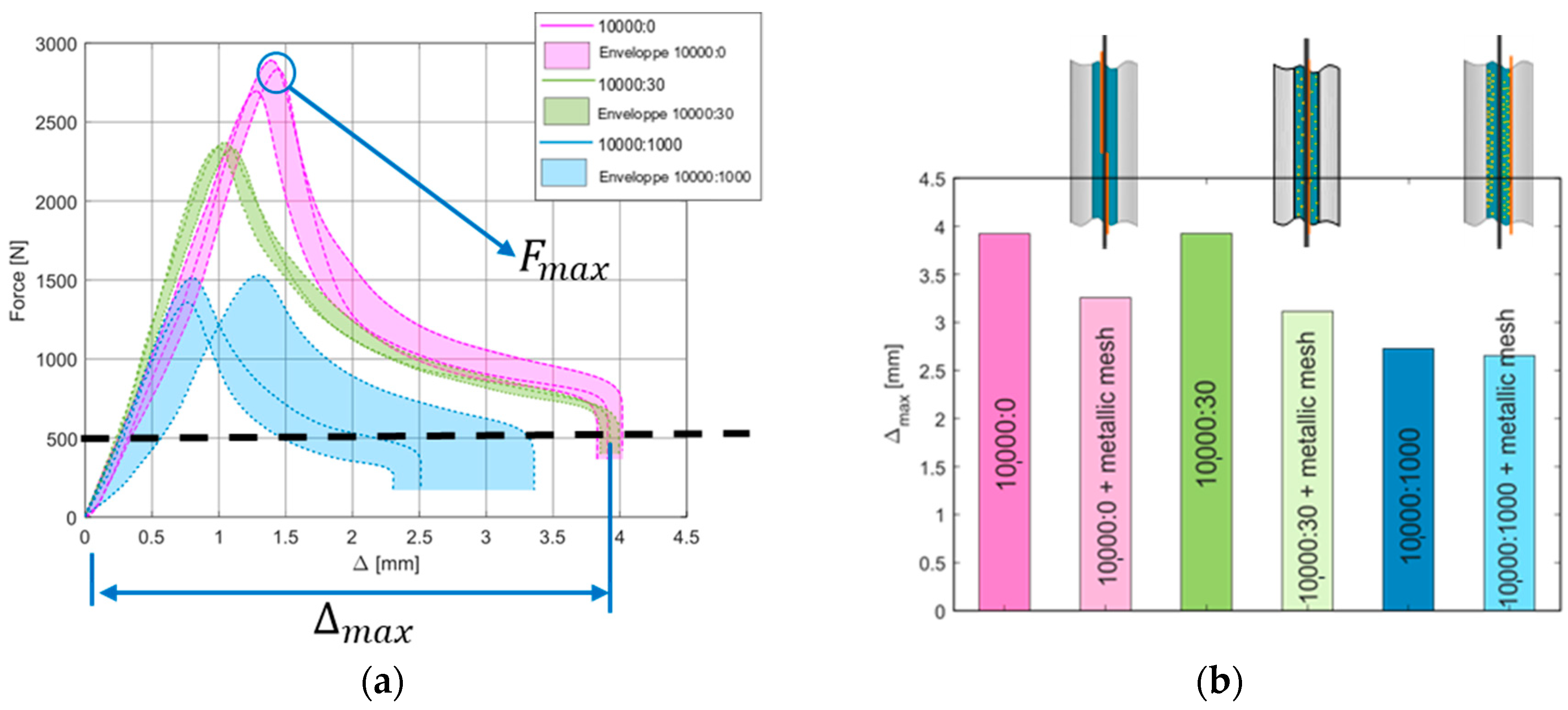
The addition of particles to the adhesive without a metallic mesh reduces the stress and strain at failure under tensile loading and narrows the uncertainties, as demonstrated during tensile tests. This phenomenon can also be observed by comparing the maximum force values for the dark colors in Figure 17a, which correspond to tests with the given percentile of TEPs and no metallic mesh.
Adding a very low mass percentage of TEPs (10,000:30) decreases the force from 2800 N to 2354 N, representing a reduction of approximately 16%. In this configuration, the particles form only clusters with some dispersed particles, as described in the previous paragraphs, and they are evenly distributed in the adhesive volume. In contrast, in the 10,000:1000 configuration, the particles are distributed with a few larger clusters. The maximum force in this case is around 1468 N, corresponding to a 47% reduction. This confirms the benefit of using a low mass percentage of TEPs if it is desirable to keep a distributed load distribution in the full adhesive volume. The choice of the trigger can be optimized, which was not the objective of this work, more focusing on proof-of-concept demonstration. Notably, failure in all cases was cohesive.
As shown in Figure 17b, the addition of a metallic mesh causes a decrease of about 31% in the maximum force for the adhesive alone (dark pink vs. light pink). For the 10,000:30 TEP configuration (green), the presence of the metallic mesh reduces this force by approximately 21%. Finally, the reduction in strength due to the metallic mesh for the 10,000:1000 configuration (blue) is only about 6%. Thus, the presence of the metallic mesh proportionally diminishes the properties more significantly when TEPs are added in small amounts. It is also noteworthy that failures involving the metallic mesh are all due to the adhesive.
Consequently, there are cross-effects between the presence of TEPs and the influence of the metallic mesh.
Another interesting phenomenon is the influence on crack initiation and propagation direction. The adhesive without particles shows poor impregnation of the mesh, which results in a crack almost completely adhesive between the adhesive and the mesh, with a change in orientation. On the other hand, the addition of particles alters the rheological properties of the adhesive, increasing its viscosity and improving the adhesive bonding to the mesh. This leads to fractures that are almost entirely adhesive between the substrate and the adhesive, in the last case.

3.3.3. SLJ Mode II Disassembly Tests

At 10 mm/min of vertical displacement to increase the load, the maximum force at rupture with no TEPs and no metallic mesh is 3750 N.
Values of time to disassemble the shear mode II specimens when the load is fixed at 500 N, which is far below this reference, and a constant current of 6A applied after reaching this mechanical load, can be found in Table 1.
The first adhesive tested was the bicomponent 3MTM EC2216, used in most of the thesis experiments, particularly to study the influence of TEPs, bonding, and strength.
When used alone, the bond did not break cleanly, leaving pieces of metal fabric attached to the substrates, which hinders clean reuse. When TEPs were added and an electric current applied, the disassembly was cleaner and more controlled, with a more distinct separation of the substrates (see Figure 18).
The Hexcel Redux® 609 adhesive, a modified epoxy film containing cotton fabric, showed different results. When used with metal fabric, the disassembly was less homogeneous. While the failure load was relatively high, some cotton fabric remained attached to the substrates after rupture, making reuse more difficult. When heating by the Joule effect is applied, the disassembly takes longer, but the separation of substrates is more homogeneous and cleaner, with no significant residues or visible damage to the composites, as was the case with the adhesive alone.
The Solvay® FM300 adhesive, designed for composite bonding applications, showed interesting results. When TEPs were sprinkled on the metal fabric without heating, the failure load was slightly reduced. When heating by the Joule effect was applied, disassembly took longer, but the separation of substrates was more homogeneous and cleaner, with no significant residues.

4. Conclusions

The proposed disassembly method presented in this paper was selected to address the need for dismantling multi-material structures assembled with a bonded joint typical of aeronautic structures. Adherends can be made of metal, composite, honeycombs, ceramic, etc. The proposed solution consists in embedding a conductive element within the adhesive joint between two adherends, to use as a trigger of thermally expandable particles judiciously distributed in the joint. The samples used for the proof of concept are made of typical aeronautic composite materials, adhesives natures, and thickness. Through the Joule effect, the adhesive joint is heated in the vicinity of the trigger, enabling the swelling of the particles without causing thermal degradation to the substrates. Using localized TEPs is an interesting strategy to demount a joint using liquid as well as film adhesives, without significant modifications of the structure or industrial assembly process. Locating TEPs near the region around the mesh allows a clean disassembly of composite substrates, whatever the adhesive used (liquid or aeronautical films). It was demonstrated that the crack initiates within the TEP clusters and occurs only if the trigger is activated. Functionalization of the adhesive bonding to control on-demand disassembly of composite aeronautical structures was demonstrated. Optimizing TEP distribution in single lap shear and double cantilever beam samples enables controlled disassembly without significantly increasing the total mass or decreasing strength. As an innovative perspective, it will be interesting to use other liquid adhesives that exhibit lower influence on the temperature.
A specific device was developed to measure the force required for substrate assembly and the adhesive distribution in complex shape substrates. This device was used to demonstrate that it is possible to introduce the metallic mesh that will easily serve as the TEP trigger during assembly without increasing the force needed for assembly. This will allow the proposed disassembly system to be used without changing the industrial process used to assemble structures of complex shape (honeycomb core of sandwich panels, double curvature antennas or plane doors, windshields, etc.). The device can also be used to evaluate and optimize the adhesive deposition to obtain the desired geometric and other properties. As a research perspective, the numerical simulations that have been performed with success to represent the adhesive expansion (while not presented here) will have to be improved upon to reproduce the correct bonding forces and the TEP clusters’ distribution.
The influence of the presence of TEPs has been demonstrated as being negligeable on the mass of laboratory samples, but non-negligeable on the strength, especially when the metallic mesh is added. Nevertheless, it is expected that after some complementary analysis, more optimum triggers and TEPs could be found to keep the properties of the joint at a desired level of requirements. A drawback of this technique is the necessity to have external access to the metallic trigger. This could be the source of an undesired trigger. As a perspective, it will be interesting to evaluate the impact of the dismantling system in aeronautical structures’ behavior under aerospace environment loads (fatigue, temperature, humidity, etc.) and its impact on certification. It also could be useful as a way to improve the numerical modeling of the functionalized joint to help model-based system engineering and improve the integration of the disassembly necessary in these industries to preserve resources on Earth.

5. Patents

This work has been patented under the reference WO2023222900.

Author Contributions

Conceptualization, L.A.S., C.E., E.P., and L.F.M.d.S.; methodology, L.A.S. and C.E.; software, L.A.S. and C.E.; validation, L.A.S., C.E., and L.F.M.d.S.; formal analysis, L.A.S., C.E., and R.C.; investigation, L.A.S., C.E., and R.C.; resources, C.E., RC, E.P., F.L., and L.F.M.d.S.; data curation, L.A.S. and C.E.; writing—original draft preparation, L.A.S. and C.E.; writing—review and editing, L.A.S. and C.E.; visualization, L.A.S. and C.E.; supervision, L.A.S., C.E., and L.F.M.d.S.; project administration, L.A.S., C.E., and L.F.M.d.S.; funding acquisition, C.E., E.P., F.L., and L.F.M.d.S. All authors have read and agreed to the published version of the manuscript.

Funding

This research was funded by the MEGEP Doctoral School and the French Ministry for higher education and research, ISAE-SUPAERO, University of Porto and University of Toulouse, and hosted by ICA and INEGI laboratories.

Data Availability Statement

The original data presented in the study are openly available at https://theses.fr/2022TOU30152 (accessed on 10 March 2025). More information regarding the PATENT WO2023222900 is available at https://patentscope.wipo.int/search/en/detail.jsf?docId=WO2023222900 (accessed on 10 March 2025).

Acknowledgments

The work and results presented in this paper were conducted in the frame of a PhD funded by the Doctoral School MEGeP. It was held in collaboration between ISAE-SUPAERO, University of Toulouse, and University of Porto. Analysis was conducted thanks to support from CNES to obtain high-quality fracture surfaces. All the administrative and technical staff of these institutions are thanked for their contribution to this work. The experimental device development and experimental fracture tests have also benefited from the key contributions of Timothée NEVEU during his internship at ISAE-SUPAERO, for which he is warmly thanked. The technical support of TTT is also thanked for its constructive and enriching contribution to the patent’s formulation and deposition. TEPs have been provided courtesy of Cie Nouryon, which is warmly thanked here.

Conflicts of Interest

The authors declare no conflicts of interest. The funders had no role in the design of this study; in the collection, analyses, or interpretation of data; in the writing of the manuscript; or in the decision to publish the results.

References

  1. Elsayed, A.; Roetger, T.; Bann, A. Best Practices and Standards in Aircraft End-of-Life and Recycling. Available online: https://www.icao.int/environmental-protection/Documents/EnvironmentalReports/2019/ENVReport2019_pg279-284.pdf (accessed on 14 January 2025).
  2. Katsiropoulos, C.V.; Chamos, A.N.; Tserpes, K.I.; Pantelakis, S.G. Fracture toughness and shear behavior of composite bonded joints based on a novel aerospace adhesive. Compos. Part B 2012, 43, 240–248. [Google Scholar] [CrossRef]
  3. Myslicki, S.; Kordy, H.; Kaufmann, M.; Créac’hcadec, R.; Vallée, T. Under water glued stud bonding fasteners for offshore structures. Int. J. Adhes. Adhes. 2020, 98, 102533. [Google Scholar] [CrossRef]
  4. Jaillon, A.; Jumel, J.; Lachaud, F.; Paroissien, E.; Renart, J. Adhesive thickness influence on a structural methacrylate adhesive behavior. In Proceedings of the 6th World Congress on Adhesion and Related Phenomena (WCARP), San Diego, CA, USA, 25 February–1 March 2018. [Google Scholar] [CrossRef]
  5. Banea, M.D. Debonding on Demand of Adhesively Bonded Joints: A Critical Review; Reviews of Adhesion and Adhesives; Scrivener Publishing LLC.: Beverly, MA, USA, 2019. [Google Scholar] [CrossRef]
  6. Boustie, M.; Berthe, L.; de Resseguier, T.; Arrigoni, M. Laser Shock Waves: Fundamentals and Applications. In Proceedings of the 1st International Symposium on Laser Ultrasonics: Science, Technology and Applications, Montreal, QC, Canada, 16–18 July 2008; Available online: https://www.ndt.net/?id=6904 (accessed on 10 March 2025).
  7. Ecault, R.; Boustie, M.; Berthe, L.; Touchard, F.; Voillaume, H.; Campagne, B.; Loison, D. Development of a laser shock wave adhesion test for the detection of weak composite bonds. In Proceedings of the 5th International Symposium on NDT in Aerospace, Singapore, 13–15 November 2013; Available online: https://www.ndt.net/?id=14947 (accessed on 10 March 2025).
  8. Kormpos, P.; Tserpes, K.; Berthe, L. Process simulation of laser shock-based disassembly of adhesively bonded composite/metallic structural parts: A numerical upscaling. J. Adhes. 2024, 101, 636–659. [Google Scholar] [CrossRef]
  9. Marques, J.B.; Barbosa, A.Q.; da Silva, C.I.; Carbas RJ, C.; da Silva LF, M. An overview of manufacturing functionally graded adhesives—Challenges and prospects. J. Adhes. 2021, 97, 172–206. [Google Scholar] [CrossRef]
  10. Tramis, O.; Hassoune-Rhabbour, B.; Nassiet, V. Structure-property relationship of nanostructured functionally graded epoxy adhesives. Int. J. Adhes. Adhes. 2021, 108, 102872. [Google Scholar] [CrossRef]
  11. Banea, M.D.; Da Silva LF, M.; Campilho RD, S.G.; Sato, C. Smart adhesive joints: An overview of recent developments. J. Adhes. 2014, 90, 16–40. [Google Scholar] [CrossRef]
  12. Lu, Y.; Broughton, J.; Winfield, P. A review of innovations in disbonding techniques for repair and recycling of automotive vehicles. Int. J. Adhes. Adhes. 2014, 50, 119–127. [Google Scholar] [CrossRef]
  13. Banea, M.D.; da Silva LF, M.; Carbas RJ, C.; de Barros, S. Debonding on command of multi-material adhesive joints. J. Adhes. 2017, 93, 756–770. [Google Scholar] [CrossRef]
  14. Nishiyama, Y.; Uto, N.; Sato, C.; Sakurai, H. Dismantlement behavior and strength of dismantlable adhesive including thermally expansive particles. Int. J. Adhes. Adhes. 2003, 23, 377–382. Available online: https://www.sciencedirect.com/book/9780128215210/materials-and-the-environment (accessed on 10 March 2025). [CrossRef]
  15. Ashby, M.F. Materials and the Environment—Eco-Informed Material Choice, 3rd ed.; Elsevier: Oxford, UK, 2021; ISBN 978-0-12-821521-0. [Google Scholar]
  16. Welsh, B.Y.; Jelinsky, S. The effect of out-gassing from commonly used spacecraft/space instrument materials on the UV-visible-IR reflectivity of optical surfaces. In Proceedings of the Photonics for Space Environments X, Optics and Photonics Conference. San Diego, CA, USA, 30 August 2025; Volume 5897. [Google Scholar]
  17. Spangenberg, J.; Uzal, A.; Nielsen, M.W.; Hattel, J.H. A robustness analysis of the bonding process of joints in wind turbine blades. Int. J. Adhesion. Adhes. 2018, 85, 281–285. [Google Scholar] [CrossRef]
  18. Nicolas, A.; Jumel, J. Double cantilever beam tests on a viscoelastic adhesive: Effects of the loading rate. Procedia Struct. Integr. 2016, 2, 269–276. [Google Scholar] [CrossRef]
Figure 1. Applications of adhesive joints in aeronautics [2] and automotive vehicles (https://www.buehnen.de/en/applications/automotive accessed on 10 March 2025).
Aerospace 12 00269 g001
Figure 2. Thermally expandable particles (TEPs) (a) before and (b) after expansion and (c) testing device used by [13,14] to force disassembly.
Aerospace 12 00269 g002
Figure 3. The three parts of our study presented on the circularity wheel of [15].
Aerospace 12 00269 g003
Figure 4. Melting process of the liquid adhesive and the TEPs and placement into a surgical syringe.
Aerospace 12 00269 g004
Figure 5. Deposition of the melted adhesive and TEPs on a plexiglass substrate (low base) before moving the upper part down to a prescribed position to reach the desired joint thickness. Letters in the figure are related to the reference of the sample.
Aerospace 12 00269 g005
Figure 6. The compression experimental device that allows the compression force to be measured by the cell (red circle pointing on the ordinate axis) as a function of vertical displacement (red arrow pointing on the abscissa axis) at constant velocity V (green arrow) and simultaneously allows the adhesive spreading from both the top and the side views to be observed as a function of time. Letters in the picture of the sample give its reference.
Aerospace 12 00269 g006
Figure 7. (a) Tension tests’ experimental setup and dimensions of the tensile samples in mm, and (b) typical distribution of TEPs and bubbles in the samples.
Aerospace 12 00269 g007
Figure 8. (a) Ultimate tensile strength and (b) probability density of ultimate strength for different TEP percentages.
Aerospace 12 00269 g008
Figure 9. (a) Dimensions and loading axes of the DCB specimens and (b) placement of the specimens in the INSTRON tensile device.
Aerospace 12 00269 g009
Figure 10. Schematic representation of the TEP clusters distribution (yellow dots) in the joint volume: no TEPs (left) uniformly distributed in the full thickness (middle) or localized around the mesh (right).
Aerospace 12 00269 g010
Figure 11. Experimental device and specimen placement for mode I disassembly tests. Each end of the trigger is connected to a current generator (maroon and blue wires) as described in the red square pointed by the red arrow. Wood hills are used to maintain the electrical conduction between the metallic mesh and the wire while isolating the rest of the setup.
Aerospace 12 00269 g011
Figure 12. (a) Dimensions in mm of the shear mode II specimens and representation of the local deformation when a tensile load is applied on each plate as illustrated by red arrows and (b) placement of the specimen into the tensile INSTRON device.
Aerospace 12 00269 g012
Figure 13. (a) Force–displacement and impregnation of complex hollow structures by the adhesive and (b) pictures of the adhesive with bubbles (holes) and TEPs clusters distribution (light colored spots).
Aerospace 12 00269 g013
Figure 14. (a) Fracture pattern showing crack initiation in TEP clusters (white ellipsoids) and (b) fractured zones in and around a TEP cluster visible on an SEM picture on which “Déc.” is for december.
Aerospace 12 00269 g014
Figure 15. (a) Failure localization in the sample and (b) SEM imaging on which “Déc.” is for december.
Aerospace 12 00269 g015
Figure 16. Tensile resistant force as a function of the opening velocity of the DCB specimens.
Aerospace 12 00269 g016
Figure 17. Influence of the addition of TEPs and metallic mesh on (a) maximum force and (b) maximum displacement: dark colors are without metallic mesh; light colors are with metallic mesh.
Aerospace 12 00269 g017
Figure 18. Cohesive fracture pattern in samples with localized distribution of TEPs and TEPs cluster near the trigger.
Aerospace 12 00269 g018
Table 1. Measured time to unbind the specimen at a constant tensile force when 6A current is injected.
AdhesiveTEPsTime to Unbound
EC2216 (liquid)Distributed80 s
Localized83 s
NoNo rupture
Redux® 609 (film)Localized55 s
FM 300 (film)Localized127 s
Disclaimer/Publisher’s Note: The statements, opinions and data contained in all publications are solely those of the individual author(s) and contributor(s) and not of MDPI and/or the editor(s). MDPI and/or the editor(s) disclaim responsibility for any injury to people or property resulting from any ideas, methods, instructions or products referred to in the content.