Article

Preliminary Aircraft Design for Hybrid Electric Propulsion Architectures: A Focus on Critical Loss of Thrust

University of Stuttgart, Institute of Aircraft Design, 70569 Stuttgart, Germany
*
Author to whom correspondence should be addressed.
Aerospace 2025, 12(4), 275; https://doi.org/10.3390/aerospace12040275
Submission received: 17 February 2025 / Revised: 20 March 2025 / Accepted: 21 March 2025 / Published: 25 March 2025

Abstract

:
Hybrid electric propulsion architectures offer a promising solution for reducing fuel consumption and emissions in aviation. However, the introduction of dual-energy carriers adds complexity to preliminary aircraft design, particularly in terms of power distribution, failure analysis, and compliance with operational regulations. Key challenges include defining failure cases, which requires refining conventional constraint analysis for hybrid electric aircraft and integrating failure scenarios into mission analysis to meet certification specifications and regulatory requirements. This study presents a unified methodology that combines an analytical constraint analysis with a higher-fidelity numerical design loop implemented in the SUAVE framework to address these challenges. Key innovations include the introduction of new parameters—such as the supplied shaft power ratio—and the ability to assess failure scenarios through the definition of the critical loss of thrust, thereby extending the analysis beyond conventional one-engine-inoperative cases. The methodology also integrates an energy management strategy that dynamically allocates power between the primary and secondary energy carriers, thereby capturing the interaction between energy (mission analysis) and power (constraint analysis) requirements. The results from both the constraint and mission analyses, including en-route alternate aerodrome scenarios, demonstrate that employing batteries as the secondary energy carrier can reduce the oversizing of primary power sources. However, their effective utilization is highly sensitive and may necessitate adjustments in energy sizing. These findings underscore the importance of incorporating dual-energy carrier considerations early in the design process and highlight the impact of critical loss of thrust conditions on hybrid electric aircraft configurations, ultimately benefiting researchers and engineers.

1. Introduction

Air transportation is important for driving economic prosperity, connecting millions of people, and providing a fast means of travel and goods transport [1]. However, environmental impacts, including carbon dioxide emissions, non-carbon emissions such as nitrogen oxides, aviation-induced cloudiness (contrails), and noise pollution, have drawn increasing public concern. Consequently, climate change and governmental regulations have imposed urgent challenges on the aviation sector to adopt more environmentally friendly practices [1,2,3].
Generally, the electrification of the powertrain expands the design possibilities for aircraft and propulsion systems. The higher efficiencies and mass-specific power of electric components [4,5] promise design advantages when optimally applied. While battery-electric aircraft generate no in-flight emissions, their range is limited by the relatively low mass-specific energy of current battery technology [4,6,7]. Conventional combustion propulsion architectures provide a significant range for aircraft but fail to meet stringent environmental objectives.
A key distinction between combustion and battery-based systems lies in the relationship between energy storage and power generation. In conventional propulsion, energy storage (fuel) and power generation (engine) are physically separate, meaning specific energy and specific power are independent. In contrast, batteries inherently couple energy storage and power generation within the same electrochemical system, linking specific energy and specific power. Although batteries offer high power conversion efficiency [4,5], they are limited by low mass-specific energy.
Aircraft design is highly sensitive to mass increases and must comply with stringent safety standards, including those for emerging technologies. Thus, the resulting design optimization challenge lies in balancing trade-offs between performance, emissions, and regulatory safety requirements. Combined with an all-electric powertrain, batteries enable new architectural opportunities, making battery-electric aircraft both efficient in power conversion and flexible in design [4,5]. This shift facilitates innovative propulsion concepts, such as distributed electric propulsion.
Different propulsion concepts and energy carriers may be suited to various aircraft types and projected availability. For long-haul and medium-haul flights, aircraft will likely rely on Sustainable Aviation Fuels (SAFs) as the most promising option until 2050 [8]. Hydrogen combustion may be suitable for short-haul aircraft, while regional and commuter aircraft allow for a wider exploration of alternative propulsion architectures and energy carriers [8]. A hybrid electric propulsion architecture with dual-energy carriers could address both the limited range of fully battery-electric solutions and the need to reduce emissions by combining a conventional primary power source, such as a combustion engine, with an electrified powertrain. In this context, primary energy carriers, such as SAF and liquid hydrogen, can be combined with the electricity stored in batteries as a secondary energy carrier. This study focuses on Jet A-1 (due to their similar characteristics compared to SAF [9,10]) and batteries as representative energy carriers. It enables various propulsion architectures [11], but integrating primary and secondary energy sources presents challenges in sizing, design, and power distribution [12].
The distribution, i.e., the Energy Management Strategy (EMS), defines the usage of the primary and/or secondary energy source and, consequently, the required energy for the mission. Scenarios like One-Engine-Inoperative (OEI) or Critical Loss Of Thrust (CLOT) in hybrid electric propulsion architectures lead to shifting power demands. These failures are challenging to incorporate into preliminary design methodologies because the propulsion architecture is not yet finalized. Equally, dimensioned propulsors are no longer viable, rendering traditional constraint analysis less effective. These interdependencies can create sizing advantages and synergies, as CLOT conditions and the number of propulsors play a decisive role in the transfer of Top-Level Aircraft Requirements (TLARs) to the preliminary aircraft design.
The novelty of this study lies in identifying failure(s) effects during preliminary aircraft design and incorporating these effects into the design and sizing process. This research emphasizes the importance of considering CLOT conditions for hybrid electric aircraft configurations and examines their impact on preliminary design. The findings aim to benefit researchers and engineers by addressing the following research questions:
  • How can a meaningful power loading be determined for hybrid electric propulsion architectures with two energy carriers?
  • What is the effect of a failure during cruise on the aircraft, especially the energy requirement of the secondary energy carrier?
In Section 2, this paper first presents the required fundamentals and state of the art necessary to obtain an overview of the challenges and opportunities of preliminary aircraft design of hybrid electric propulsion architectures. Then, in Section 3, the methodology is described to analyze the power and energy requirements. Finally, the results of the constraint analysis and mission analysis for failures and operational regulations are given in Section 4.

2. Fundamentals and State of the Art

This chapter provides an overview of the fundamentals and discussion of the current state of the art, which is essential for understanding the challenges addressed and formulating the hypothesis of this paper. First, hybrid electric propulsion architectures and key definitions are clarified. This is followed by a discussion of opportunities in mission analysis, with a focus on EMSs and operational regulations. Next, the challenges in determining the required power for hybrid electric propulsion architectures are examined.

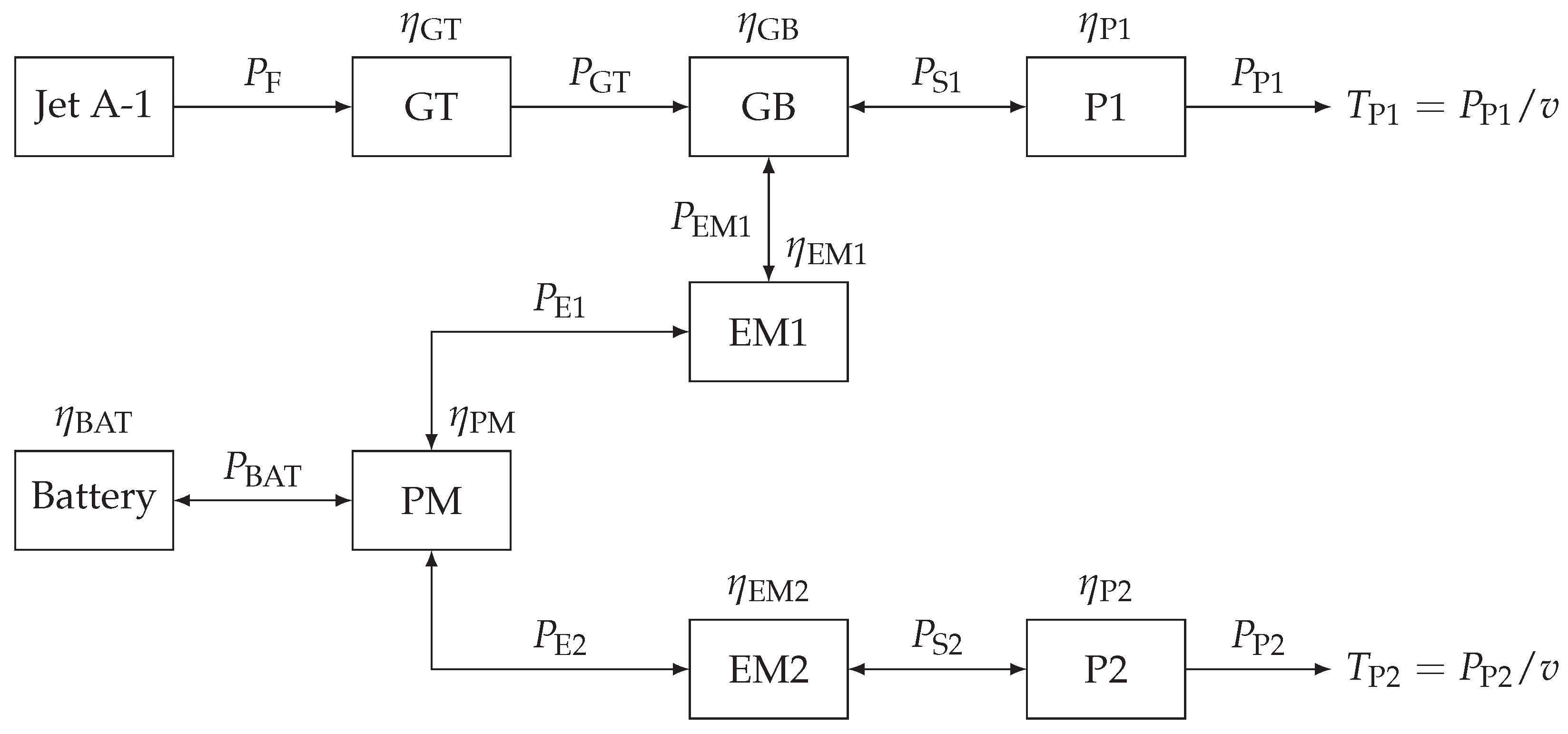
2.1. Hybrid Electric Propulsion Architectures

Hybrid electric propulsion architectures integrate multiple energy carriers (e.g., batteries, hydrogen, SAFs) with various power sources (e.g., internal combustion engines, fuel cells, electric motors) to generate thrust. In contrast, conventional systems rely on a single energy carrier and one type of power source, simplifying their definition through the number of equivalent components. However, for hybrid electric propulsion architectures with multiple energy carriers, power sources, and power paths, additional variables and parameters are required to define the system of equations.
There is a distinction between an energy carrier and an energy source. An energy carrier refers to a system or component that contains energy. As previously mentioned, the number of components is significant; therefore, multiple sources of a single energy carrier are referred to as multiple energy sources. For example, two fuel tanks of Jet A-1 would represent one energy carrier and two energy sources. A similar distinction applies to power sources: the type of power source refers to a specific type of conversion, while the power source refers to the number of sources. For example, an aircraft with two turbofan engines has two power sources but only one type of power source. This distinction is relevant for redundancy, failure analysis, certification, and regulations, as discussed in Section 2.3.
Hybrid electric propulsion architectures with multiple energy carriers require careful consideration of the distribution of energy sources and the type of power sources employed. One particularly promising architecture is the Serial-Parallel Partial-Hybrid (SPPH), which utilizes two energy carriers (see Figure 1). Other dual-energy carrier propulsion architectures, such as hydrogen fuel cell and battery systems, are not considered in this study due to the additional complexity involved in higher-fidelity modeling. However, the methodology and analysis developed in this study remain applicable to such systems.
The figure for this propulsion architecture shows the system components (represented as rectangles) along with their efficiencies, defined as η i = P i , out P i , in , displayed above each component. The power flow paths (depicted by arrows) indicate the associated output power P i . If the arrows point in both directions, this indicates a possible reverse power flow. The number of respective components is not shown for clarity.
The SPPH architecture includes two energy carriers: Jet A-1 as the primary energy carrier and a battery as the secondary carrier. This configuration features two power paths. As illustrated in Figure 1, the primary power path consists of a gas turbine (GT) supplied with fuel power P F (defined as the product of the lower heating value and mass flow rate), followed by a gearbox (GB) and a primary propeller (P1). The secondary power path includes a battery (BAT) connected to a power management (PM) component, followed by a secondary electric motor (EM2) that receives the secondary electric power P E 2 and a secondary propeller (P2). The PM component represents, in the first approximation, multiple power conversion and distribution units, such as a DC/DC converter or a DC/AC inverter. In this context, the PM is modeled as a component with an associated conversion efficiency. The two power paths are interconnected through the electric motor (EM1), which handles the corresponding primary electric power P E 1 , enabling power exchange between the primary and secondary paths. The propellers convert shaft power P S into propulsive power P P , which is then transformed into thrust T P together with the flight velocity v.
This propulsion architecture also distinguishes between the primary and secondary propellers, allowing for different sizes of each. This setup supports various power distribution strategies, such as boosting both propellers using power from the battery. For the SPPH, nine feasible operating scenarios are identified [14], made possible by the reverse power flow capability of the electric components.
As mentioned above, the categorization of hybrid electric propulsion architectures requires new parameters and variables due to the absence of a single power path. One approach to categorizing hybrid electric propulsion architectures is through the degree of hybridization. However, two fundamental definitions are essential for this categorization, particularly because of the distinction between energy sources and power sources. The first is the hybridization factor of power H P in Equation (1), which relates the electric motor shaft power P S , electric to the total shaft power P S , total , i.e., the sum of the electric motor shaft power and the gas turbine power P S , GT :
H P = P S , electric P S , total = P S , electric P S , electric + P S , GT
Secondly, the hybridization factor of energy H E , as defined in Equation (2), characterizes the ratio of electrical energy E BAT to total energy E total for a mission. Unlike H P , this comparative parameter depends on the range and payload of the current mission.
H E = E BAT E total = E BAT E BAT + E F
For the comparison of various propulsion architectures, these two hybridization factors are beneficial because they show the ratio of electrical power ( H P ) as well as the usage of the battery as an energy carrier ( H E ). The classification and comparison of propulsion architectures can be represented by the two hybridization factors [15,16]. However, it should be noted that hybridization factors can also take mathematically negative values. For H E , this occurs if the battery has a higher State of Charge (SoC) at the end of the mission than at the beginning. Additionally, H E depends on the range and payload of the current mission as it varies with the respective shares of the flight segments and the fuel requirements. If H P is considered a mission variable, a negative factor may arise when the electric motor operates in generator mode. Furthermore, treating H P as a mission variable rather than a constant parameter could be necessary in cases where gas turbine performance is affected by altitude, for example.
Therefore, it is essential to clarify the definitions of H P and H E . In the context of preliminary aircraft design and constraint analysis, gas turbine power (loading) is always normalized to Sea-Level Static (SLS) International Standard Atmosphere (ISA) conditions to facilitate comparisons across different requirements. Accordingly, H P can be reformulated as the hybridization factor of installed power, H P , SLS , to account for these standardized conditions. Often, research does not clearly specify whether hybridization factors are treated as mission variables or fixed parameters, leading to inconsistencies in analysis and interpretation.
For preliminary propulsion system sizing, the hybridization factor of installed power can be used in conjunction with power loading to determine the actual power requirements of the electric motor(s) and gas turbine(s), considering the respective numbers of primary and secondary power sources. However, the overall propulsion system size cannot be determined solely using the hybridization factors of installed power ( H P , SLS ) and energy ( H E ), as these factors define ratios at different points within the powertrain. Specifically, H P , SLS applies at the propeller shaft, while H E pertains to the energy carriers. This distinction introduces a dependency between the two factors as they are linked through time, following the relation E = P · t .
Additionally, if looking at the power provided by the energy carriers, the supplied power ratio Φ defined by Isikveren et al. [17] can be expressed as
Φ = P sup , b P sup , a + P sup , b
The supplied power ratio relates the power of the secondary energy carrier P sup , b to the total supplied power (i.e., the sum of the power of the primary energy carrier P sup , b and the power of the secondary energy carrier P sup , b ). As outlined by de Vries et al. [13], when the battery is designated as the secondary power source and fuel as the primary power source, Equation (3) simplifies to
Φ = P BAT P F + P BAT
Furthermore, the supplied power ratio can be linked to H E by integrating the supply power ratio over time. Physically, this integral represents the evaluation of the total mission energy ( H E ) , rather than focusing solely on a single mission point (supplied power ratio).
However, various methods exist for applying the specified parameters in the classification of hybrid electric propulsion architectures [11,12,13,18,19]. As previously mentioned, these parameters can serve as aircraft comparison metrics, sizing parameters, or mission variables. The key distinction lies in the fact that mission variables vary depending on the flight segment or mission phase under analysis, ensuring that the appropriate strategy is applied. Consequently, the EMS dictates how energy is utilized throughout the flight mission and can be expressed using different variables. A detailed analysis of these approaches and their effects on energy consumption (mission analysis) and performance (constraint analysis) is provided in Section 2.2 and Section 2.3.

2.2. Mission Analysis: An Energy Perspective

The use of two energy carriers in hybrid electric propulsion architectures introduces greater complexity to mission analysis compared to conventional architectures. This section provides an overview aimed at presenting the associated challenges and deriving hypotheses about the effects of multiple energy carriers on the energy considerations in preliminary aircraft design. Various methods for conducting mission analysis are introduced, followed by an examination of the EMS and its influences. In addition, special attention is given to operational regulations that require consideration in this context.
For conventional architectures with a single energy carrier and one type of power source and propulsor, the mission energy or fuel mass can be calculated using the Breguet equation [20,21,22]. While the Breguet equation can also be adapted for battery-electric architectures [6,7], its applicability is limited in cases involving multiple energy carriers and multiple types of power sources due to its boundary conditions. As a result, the Breguet equation is typically used only for segments involving steady horizontal flight, such as cruise, alternate, or holding phases.
Nam et al. [23] developed a preliminary aircraft design methodology (constraint and mission analysis) that accounts for multiple energy carriers and power paths. The power paths are not interconnected, which simplifies equation-solving by utilizing analytical mass fractions based on specific energy, including scenarios where the aircraft mass remains constant for battery-electric configurations [23]. Furthermore, de Vries et al. [24] proposed a simplified hybrid electric propulsion architecture that reduces the complexity of range estimation formulas and provides a practical approach for cruise flight analysis, in line with similar work by Joksimovic et al. [25]. While these approaches offer valuable frameworks for specific use cases, they do not yet enable comprehensive mission analysis across all flight phases, unlike Nam et al. [23]. Since traditional mass fraction methods [20,21,22,26] are typically limited to Jet A-1 fuel, new methodologies are essential to accurately determine energy requirements for alternative fuels and hybrid electric aircraft.
Numerical mission analysis is essential for hybrid electric propulsion architectures as it eliminates the need for new analytical equations while still providing valuable performance insights. SUAVE [27,28], an open-source preliminary design environment, enables numerical mission analysis through an iterative flight segment approach that does not rely on the Breguet equation. Additionally, SUAVE incorporates common handbook methods [20,21] and supports the adaptation of existing methods, the implementation of new surrogate models (multidisciplinary), and extensions to higher-fidelity models (multi-fidelity). Recognizing these advantages, Karpuk et al. [29] and Ma et al. [30] developed an initial sizing framework based on SUAVE. The implementation of numerical mission analysis will be presented in Section 3.2.

2.2.1. Energy Management Strategy

The utilization of energy carriers and their distribution across different types of power sources significantly influence their respective sizing and, consequently, the overall mass of the energy carriers. Given the differences in mass-specific energy and power between Jet A-1 fuel and batteries, the efficient use of the battery is essential. Otherwise, the mass-sensitive nature of the preliminary aircraft design may be negatively impacted. For instance, Jet A-1 fuel has a mass-specific energy of approximately 12.0 kWh/kg [31,32], whereas batteries currently achieve, depending on technology and future advancements, between 0.2 and 0.6 kWh/kg at the cell level [33].
One of the key advantages of hybrid electric propulsion architectures is their significant higher power conversion efficiency from chemical energy to shaft power (losses due to heat generation). Batteries reach discharge efficiencies of 95 to 99% [34,35], while cables and power converters contribute additional efficiencies of approximately 99% and 95%, respectively [36,37]. This results in an overall powertrain efficiency (excluding gearbox and propeller) of approximately 80%, compared to only 25 to 55% for conventional combustion engines [4].
To fully leverage the benefits of hybrid electric propulsion and achieve meaningful synergies, the battery must be strategically employed as an energy source. The main challenge is to integrate and implement an appropriate EMS within the preliminary aircraft design and mission analysis. The subsequent section will provide an explanation and discussion of the current state of the art.
Quillet et al. [38] used the hybridization factor of power H P to define and divide parallel hybrid electric propulsion architecture. To control the use of the electric motor during the mission, Quillet et al. [38] introduced a new variable, adapted from Hoelzen et al. [39]. This variable basically represents the throttle of the electric motor.
While this approach provides a valuable way to represent the distribution strategy, Quillet et al. [38] defined the equation for determining the current power of the electric motor only for two specific cases, thus limiting the analysis to two possible distribution strategies. Therefore, the actual power split between the primary and secondary energy carriers results as an outcome, contrasting with the method of de Vries et al. [13]. Bovet et al. [14] analyzed the EMS for the SPPH propulsion architecture (as shown in Figure 1) adapted from de Vries et al. [40], using a Monte Carlo optimization approach to determine the optimal EMS for each flight segment while managing computational complexity. Leite et al. [41] emphasized that optimizing EMS enhances hybrid electric aircraft design by minimizing block fuel consumption, as hybrid systems require selecting between multiple energy sources, unlike conventional aircraft. Although their study explores various strategies, it does not incorporate a full design loop with aircraft resizing, which could reveal stronger EMS influences due to snowball effects.
Conventional methods do not address hybrid electric propulsion architectures [16] as these lack sufficient operational flexibility. Moreover, integrating multi-energy carrier systems introduces additional challenges, including higher sensitivities and synergies [42]. This complexity can be managed through a multidisciplinary design and optimization framework [42]. Systematic analysis of flight conditions is crucial, but no current analytical method exists to identify an optimal design point that accounts for the distribution and utilization of primary and secondary energy carriers throughout a mission. Developing such a method would improve the efficiency of identifying optimal configurations.

2.2.2. Operational Regulations

Operational regulations [43] establish performance and reserve requirements for aircraft, covering fuel planning, reserve policies, and operational performance under normal and failure conditions. Performance Class A aeroplanes [43], defined as multi-engine aircraft with a maximum operational passenger seating configuration above nine or a Maximum Take-Off Mass (MTOM) exceeding 5700 kg, serve as a basis for these operational regulations.
Pre-flight calculations of usable fuel or energy must comprehensively account for operational requirements. According to CAT.OP.MPA.181(c) [43], operators are required to calculate fuel or energy consumption of the flight. These fuel requirements can be divided into two groups from the perspective of preliminary aircraft design. Firstly, regulatory reserves that are typically considered during the design phase are summarized as follows:
  • Contingency fuel: 3% of planned trip fuel/energy [43]
  • Destination alternate fuel: 50 to 200 NM [44]
  • Final reserve fuel: 30 min at holding speed at 1500 ft [43]
These reserves are incorporated into the aircraft design and mission analysis (see Section 2.2 and Section 3.2). However, they primarily account for external influences, such as adverse weather conditions at the destination aerodrome, rather than aircraft failures.
Secondly, there are additional fuel reserve requirements related to propulsion system failures that are often excluded from consideration in conventional single-energy carrier aircraft as they have a limited impact on such designs. This is because conventional reserve policies (contingency, alternate, and holding) already fulfill regulatory requirements for a failure in the propulsion system, since no differentiation between energy carriers is necessary; all available energy (fuel) remains usable by the remaining power sources (engines). Consequently, in conventional preliminary aircraft design based on Jet A-1, many operational regulations related to propulsion system failures are often not actively considered during the early design phase as they are implicitly covered through standard reserve provisions.
For example, in conventional propulsion architecture, if one combustion engine fails, the remaining engine(s) can utilize the entire fuel quantity, ensuring that sufficient energy remains available. In contrast, for hybrid electric propulsion architectures, a failure in the primary power path (e.g., combustion engine) means that the secondary power path (e.g., battery-electric) must compensate for a longer duration than it may have been originally sized for. This introduces new challenges for reserve sizing and energy management.
Thus, energy reserve requirements associated with propulsion system failures, which are implicitly covered in conventional designs, must be explicitly reconsidered in hybrid electric propulsion architectures and may become a decisive factor in flight route planning and regulatory compliance.
For instance, regulation CAT.OP.MPA.181(c)(6) [43] mandates additional reserves to ensure that an aircraft can reach an En-Route Alternate (ERA) aerodrome in case of a failure increasing fuel or energy consumption. Similarly, CAT.OP.MPA.140 [43] restricts the maximum distance from an adequate aerodrome for twin-engine aircraft without ETOPS approval, limiting operations to within 60 min of OEI cruising speed.
Performance regulations establish minimum climb rates, with CAT.POL.A.410 [43] requiring 300 ft/min under maximum continuous power and CAT.POL.A.415 [43] reducing this to 150 ft/min in OEI scenarios. Additionally, OEI ceiling constraints mandate a minimum obstacle clearance of 1000 ft, as specified in CAT.POL.A.215 [43], necessitating detailed route analysis to mitigate risks associated with engine failure over high terrain. While this study focuses on ERA, it is important to note that regulations also impose take-off alternate requirements, as outlined in AMC1 CAT.OP.MPA.182 [43].
Hybrid electric propulsion architectures introduce new challenges in meeting operational regulations, which are typically not crucial for conventional aircraft relying on a single energy carrier. In hybrid systems, multiple energy carriers require adjustments to existing regulations, which must now account for the contributions of each carrier. The distribution and integration of the EMS lead to varying consumption rates between primary and secondary carriers, impacting energy and power constraints in failure scenarios. This section discusses the influence of operational regulations on hybrid electric aircraft design, focusing on failure scenarios, energy management, and compliance with reserve requirements, highlighting the need to address regulatory gaps for safe integration.
Quillet et al. [38,45] emphasized the significant impact of OEI segments on fuel consumption and the necessity of considering failure scenarios in hybrid electric aircraft. Quillet et al. [45] highlighted the role of secondary energy carriers in enhancing operational flexibility through EMSs. Similarly, Boggero et al. [46] integrated operational regulations and certification requirements, analyzing emergency landings after engine failure and demonstrating their substantial influence on the size and mass of the secondary energy carrier, ultimately affecting overall aircraft design. Finger et al. [47] examined the impact of reserves and OEI scenarios on aircraft design, showing that alternate range requirements can significantly increase MTOM by 10 to 50%. While their study underscores the importance of failure considerations in hybrid electric aircraft design, it focuses primarily on combustion engine failures [47], highlighting opportunities to extend the analysis to additional critical failure scenarios relevant to hybrid electric propulsion architectures.
Unlike conventional aircraft design, considering OEI in a detailed additional mission analysis is uncommon. Sizing with reserves provides sufficient fuel (energy) and ensures that the power constraint is met for sustained flight with OEI. Therefore, there is no need for operational regulations with failures. However, this assumption needs validation for hybrid electric aircraft with two energy carriers, as the secondary energy source could be included in the power constraint for failures. Moreover, the energy requirement for the additional mission is often not included or is simplified. This discrepancy needs to be investigated and incorporated into the sizing and design process. For hybrid electric aircraft, however, these procedures or operational regulations are not yet defined and require further investigation. Therefore, the influence of OEI on preliminary aircraft design represents a research gap.

2.3. Influences and Parameters in Required Power Analysis

The design of hybrid electric propulsion architectures becomes more intricate due to the introduction of new variables, resulting in numerous possible parameter combinations. This complexity also impacts the determination of the required installed power as hybridization alters the altitude dependency of the powertrain. Specifically, electric motors and batteries are not directly influenced by changes in air density. A constraint analysis is conducted to determine and evaluate specified performance requirements in the preliminary aircraft design. These requirements are primarily derived from customer-specific specifications, market analyses, certifications, and regulations. For the preliminary aircraft design, they serve as inputs and are collectively summarized as TLARs. The conventional constraint analysis and the respective sizing chart are fundamentally explained in all common preliminary aircraft design books [20,21,26,48,49] and are not discussed further. This investigation focuses on transport aircraft, specifically large aeroplanes certified under Certification Specification CS-25 [50] (i.e., MTOM > 8618 kg) and operated under Performance Class A [43] (i.e., MTOM > 5700 kg), which form the foundation of this analysis. The methodology presented in this study is not limited to a specific aircraft size and remains applicable to a wide range of aircraft types. Fundamentally, the method focuses on integrating hybrid electric propulsion architectures within a framework that accounts for energy and power considerations.
This section aims to describe the influences and parameters necessary to meaningfully determine the required power of a hybrid electric propulsion architecture. First, existing methods for selecting the design point in the sizing chart are described and critically reviewed. Second, the influences of the EMS (see Section 2.2.1) are discussed in relation to the performance requirements to present possible scenarios. Finally, the methods for redundancy and failure considerations are reviewed and discussed, with reference to operational regulations (see Section 2.2.2).
As mentioned, Nam et al. [23] developed a methodology for the constraint analysis of hybrid electric propulsion architectures. To further enhance their methodology, Nam et al. [51] introduced separate sizing charts for the primary and secondary powertrains. However, optimal aircraft performance could not be determined through constraint analysis alone as differing powertrain responses to altitude create multiple design optima [51]. Moreover, Nam et al. [23] did not address potential powertrain failures, revealing a gap in the analysis of CLOT scenarios in hybrid electric architectures. Therefore, a comprehensive mission analysis, including detailed mass breakdown, is essential for accurate sizing.
Finger et al. [18,52] proposed a degree of hybridization-based method for selecting a design point, allowing for the downsizing of the gas turbine by distributing power between electric motors and the combustion engine. However. the full effects of hybridization on constraint equations, such as the altitude independence of electric motors, are not yet fully incorporated, which may lead to oversizing [19,53]. Additionally, aerodynamic interactions from flexible propeller placement remain unaddressed, representing an area for further research.
De Vries et al. [13,40,54] introduced a universal equation for all constraints, incorporating both primary and secondary powertrains through a shaft power ratio. Their method employs three power control variables to solve the equations [54], making powertrain sizing mission-dependent. However, this approach also presents new challenges because it merges design parameters with operational variables, complicating direct comparability with conventional design methods and requiring multiple sizing charts. Furthermore, it does not inherently optimize mission-dependent variables to enhance component utilization.

2.3.1. Mission Influences: A Power Perspective

The EMS plays a crucial role in hybrid electric propulsion architectures, as discussed in Section 2.2.1. While Nam et al. [51] implicitly incorporated an EMS into their constraint analysis by varying power contributions across flight segments, Finger et al. [55] highlighted that minimizing power loading does not necessarily result in the lowest MTOM due to battery mass considerations. However, their analysis is based on a simplified EMS, where the combustion engine primarily powers the aircraft [47], limiting the potential for flexible power distribution.
Boggero et al. [46] integrated an EMS directly into their design methodology, optimizing power distribution following an OEI scenario. Although their approach effectively reduces combustion engine size [46], it applies a fixed EMS, which restricts the hybridization potential. Increasing EMS flexibility across flight phases could further improve design optimization.
Overall, defining an adaptable EMS in early design stages is essential for optimizing hybrid electric aircraft, enabling efficient power distribution while minimizing mass penalties. Future methodologies should incorporate flexible EMS considerations into constraint analysis to improve performance and expand the feasible design space.

2.3.2. Redundancy and Failures

Hybrid electric propulsion architectures complicate OEI conditions due to multiple energy and power sources and require the re-evaluation of power requirements based on their distinct characteristics. Redundancy benefits only arise when both multiple energy carriers and types of power sources are employed. This section reviews existing OEI methodologies for hybrid electric propulsion, identifying gaps and exploring their implications for constraint analysis. Current certification regulations (e.g., CS25.1309, CS25.121) [50] primarily address conventional systems, necessitating adaptations for hybrid electric architectures [11].
In preliminary aircraft design, the redundancy of conventional propulsion architectures is addressed using the well-established oversizing factor f OS , conv for a single failure and the number of engines n eng , expressed as follows [20,26]:
f OS , conv = n eng n eng 1
As outlined in Section 2.1, conventional OEI definitions assume equally sized power sources, making the traditional oversizing factor inadequate for hybrid electric configurations. To address this challenge, the certification for normal-category aeroplanes CS-23 [56] (i.e., MTOM < 8618 kg) introduces CLOT, which considers failures across the power path, ensuring a more flexible and realistic safety framework.
De Vries et al. [13] highlighted that hybrid electric propulsion introduces multiple OEI constraints depending on the failed powertrain component. While failure scenarios are complex and case-specific [13], accurately predicting them during preliminary design is crucial for meeting certification requirements. In architectures with two energy sources and an appropriate powertrain configuration, the oversizing factor can be reduced. For instance, if a primary powertrain fails, the secondary powertrain can sustain operation.
Sgueglia et al. [57] integrated certification constraints into a multidisciplinary design framework, emphasizing that OEI conditions for dual-energy carrier systems are still undefined and require further clarification. Distributed propulsion further complicates failure analysis as individual propeller failures are less critical than in conventional designs [57]. Steiner et al. [58] proposed a simplified approach to redundancy calculations by assuming uniformly sized propulsion devices, offering a practical means to address redundancy. However, their method does not account for the distribution of energy sources or dependencies within the wiring, highlighting opportunities for further refinement.
Marciello et al. [59] analyzed a large number of potential failure cases, demonstrating that different EMSs lead to varying outcomes. Their study suggests that energy redistribution strategies could optimize EMS settings during preliminary design [59]. Similarly, Finger et al. [47] showed that OEI constraints significantly restrict the design space as aircraft performance depends on battery technology and alternate mission requirements. These findings underscore the need for a comprehensive failure analysis framework to optimize hybrid electric propulsion architectures.

2.4. Conclusion and Identification of Research Gaps

The hypotheses in this section form the basis of this research, linking objectives and expected outcomes. The investigation of hybrid electric propulsion architectures with dual-energy carriers, focusing on CLOT, is grounded in a thorough review (see Section 2).
The first research question examines how hybrid electric propulsion architectures affect constraint analysis, emphasizing the need to integrate EMS and failure scenarios. A comprehensive power loading can be derived analytically to ensure compliance with safety standards and optimize performance, while distinguishing between sizing and mission variables supports a robust design process.
The second research question explores the impact of operational regulations on hybrid electric propulsion, which must satisfy reserve and failure requirements for both energy carriers and power paths. An early integration of energy constraints is essential for regulations. In particular, a CLOT event may require new energy sizing criteria for the secondary energy carrier, directly affecting mission feasibility.

3. Methodology

To address the research questions, a structured and comprehensive methodology was developed. It began with a detailed analysis of hybrid electric propulsion architectures, focusing on configurations that utilize dual-energy carriers, such as Jet A-1 fuel and batteries. This study integrated theoretical frameworks, numerical modeling, and simulation tools to evaluate power and energy requirements and assess their implications for aircraft design and performance.
First, mathematical models were derived to describe the relationships between power (thrust) requirements based on the TLARs, with particular emphasis on certification specifications and operational regulations. Critical influences and parameters, such as failure scenarios and EMSs for hybrid electric propulsion architectures with two energy carriers, were incorporated into the analytical constraint analysis to initialize the preliminary aircraft design process.
Second, an enhanced SUAVE environment was developed to iteratively size the aircraft through a sizing loop that ensured that all requirements were met. The energy network was adapted to account for the critical factors identified, thereby enabling a comprehensive numerical analysis of constraints and operational regulations.
This methodology facilitated a systematic exploration of power and energy requirements for hybrid electric propulsion architectures, providing a robust foundation for informed decision-making and effective design optimization.
Due to the focus on two energy carriers, a new preliminary design variable was needed to relate the secondary to the primary energy carrier. As noted in Section 2.1, there are multiple ways to relate the power and energy variables of propulsion architecture. However, the challenge lies in determining whether these parameters should be treated as mission variables or design parameters. In the context of numerical analysis (see Section 3.2), an energy-based variable for the preliminary design is not useful as it depends on the mission and thus arises as an outcome of the mission analysis—similar to the analytical fuel calculation in conventional aircraft design using the Breguet equation. Furthermore, in analytical constraint analysis (see Section 3.1), which investigates power requirements, the parameter must be power-dependent.
Consequently, the preliminary design parameter for hybrid electric propulsion architectures with two energy carriers must be based on power. In this regard, two variables are reviewed: the hybridization factor of power ( H P ) and the supplied power ratio ( Φ ). The disadvantage of H P is that it is defined at the propeller shaft level, providing no direct information about the individual energy carriers and being influenced by the power distribution.
Although Φ can be used to compare energy carriers, the primary power source (e.g., a gas turbine or fuel cell) experiences significant power losses due to conversion efficiencies (see Section 2.2.1). Furthermore, this efficiency varies with the operating point and atmospheric conditions. For these reasons, the present investigation adopted a parameter defined based on the first energy conversion in the primary power path. Similar to Φ , the supplied shaft power ratio Φ S , SLS is introduced to compare the battery power P BAT , SLS (i.e., the power of the secondary energy carrier) to the sum of the battery power and the gas turbine shaft power P GT , SLS (i.e., the power of the primary energy carrier), with each quantity normalized to SLS, ISA conditions:
Φ S , SLS = P BAT , SLS P BAT , SLS + P GT , SLS
To differentiate the supplied shaft power ratio from the conventional supplied power ratio, note that the supplied shaft power ratio refers to quantities that are typical in aircraft preliminary design, such as P GT , SLS . This parameter is used, for example, in mass calculations or in defining power-specific fuel consumption and represents a classic design and comparison metric for aircraft. Although a battery is not primarily affected by atmospheric conditions, it was also normalized because it could be substituted by another secondary energy carrier that may be influenced by such conditions. The same consideration applied to the gas turbine. This new parameter served as the foundation for the methodology developed in this investigation. The advantages of using this approach in preliminary aircraft design for hybrid electric propulsion architectures are discussed in the following sections.

3.1. Analytical Constraint Analysis

Constraint analysis, illustrated by the sizing chart, is crucial for various aspects of preliminary aircraft design, as described in Section 2.3. On the one hand, the potential design window delineates non-physical limits and boundaries dictated by requirements and regulations. On the other hand, by strategically selecting the design point, a meaningful definition of the power loading of the aircraft P total / m 0 and wing loading m 0 / S can be established early in the process. Nevertheless, constraint analysis is not only to be executed once at the beginning but must be constantly adapted through the iterative preliminary aircraft design in order to adopt the changes. As already shown in the hypothesis, constraint analysis for hybrid electric propulsion architectures should in particular be able to represent failures (see Section 3.1.1) and thus the CLOT as well as the distribution of the energy carriers, i.e., the EMS (see Section 3.1.2).
The methodology for the constraint analysis will be elaborated upon in subsequent sections, particularly regarding the OEI ceiling requirement. Other requirements—and therefore the corresponding equations, such as those for cruise speed and altitude—can be adapted but are not described in detail here. In the event of an engine failure during cruise, the aircraft must maintain a specified altitude and climb rate, as outlined in Section 2.2.2. This designated altitude is critical for navigating over or around obstacles, such as mountains. Consequently, an additional energy constraint is essential for mission planning and determining the necessary fuel reserves; this is addressed in Section 3.2.
The normalized required power loading of propeller aircraft, P total , i , SLS , j m 0 , is a key parameter for assessing the constraint ( i ) [21,26,48]. This metric is especially relevant for conventional propulsion architectures that employ propellers, taking into account different types of power sources ( j ) , such as combustion engines. An example is provided in Equation (7), which shows the formulation for OEI scenarios (reflected in the oversizing factor f OS , conv ) considering the required vertical speed [21,26,48]:
P total , i , SLS , j m 0 = g · v i η P · 1 α i , j · β i · f OS , conv · v v , i v i + 1 L / D i
The power loading calculation incorporates several essential aerodynamic and performance variables. The MTOM is denoted as m 0 , while g represents the gravitational acceleration constant. The velocity components of the aircraft include the horizontal speed v i and the vertical speed v v , i . The lift-to-drag ratio L / D i is an aerodynamic parameter and η P represents the propeller efficiency.
Additional parameters include the power lapse ratio α i , j , as defined in Equation (8), which relates the actual shaft power P i , j to the normalized SLS, ISA shaft power P i , SLS , accounting for atmospheric conditions such as changes in air density with altitude and increasing Mach numbers.
α i , j = P i , j P i , SLS
The mass ratio β i , given in Equation (9), represents the ratio of the actual aircraft mass m i to the MTOM, which is necessary to normalize the power loading to the MTOM.
β i = m i m 0
To extend the performance assessment and constraint analysis to hybrid electric propulsion architectures, additional considerations must be incorporated beyond those for conventional propulsion architectures. As previously mentioned, conventional aircraft typically rely on a single energy carrier and a single power source. In contrast, hybrid electric architectures introduce multiple energy carriers and power sources, which significantly affect failure scenarios and power distribution. Therefore, the following sections first address potential failure considerations and then examine power distribution aspects through the EMS.

3.1.1. Failure Consideration

Failure considerations in hybrid electric propulsion architectures are more complex than in conventional systems due to the unequal sizing of propulsion components and the increased number and variety of components (see Section 2.3.2). Consequently, the failure methodology—particularly for thrust loss and identifying the CLOT—must differentiate among various propulsion component sizes to effectively assess the implications of such failures. A key parameter in this analysis is the conventional oversizing factor f OS , conv (see Equation (5)), which quantifies the additional power margin needed to ensure safe operation under failure conditions. Understanding the role of this factor (see Equations (10) to (14)) is crucial for ensuring redundancy, maintaining performance, and satisfying regulatory compliance.
The oversizing factor is multiplied by the ratio of the single-engine power, P eng P eng , which is mathematically equal to one and serves as a formal step to allow for the subsequent algebraic manipulation of the equation:
f OS , conv = n eng n eng 1 · P eng P eng
Expressing this in terms of the total aircraft power P total yields
f OS , conv = P total P total P eng
P k = P eng denotes the power lost from the k-th power source. Equation (12) demonstrates how the total power compares to the net power available after one engine fails:
f OS , k = P total P total P k
Let ϕ k denote the fraction of the total power P total and the loss of power due to a failure P k , i.e., the power split of a failure ϕ k :
ϕ k = P k P total
It is important to note that P total and P k can be defined at different levels of the powertrain—for example, at the propeller shaft level or at the level of the supplied power from the energy carrier—depending on the context of the analysis. This distinction is necessary because ϕ k may vary depending on the evaluation level within the hybrid electric propulsion architecture, as the power distribution can differ at various stages. For instance, in an architecture employing two batteries as energy carriers and eight electrically driven propellers, the failure of one of the two batteries would have a much greater impact than the failure of one of the eight propellers.
Factoring out P total in the denominator and substituting ϕ k yields the following simplified expression for the oversizing factor:
f OS , k = P total P total ϕ k · P total = 1 1 ϕ k
These equations demonstrate how the oversizing factor f OS can be expressed in different but equivalent forms: from a ratio based on the number of engines to a ratio involving total installed power and the power lost in a failure scenario. Ultimately in a general form, ϕ k represents the share of the total power contributed by the k-th source, while f OS indicates the oversizing factor required when that fraction of total power is lost.
Zamboni et al. [60,61] calculated a similar oversizing factor for hybrid electric propulsion architectures. However, their approach neither provides a detailed derivation of the oversizing factor nor explicitly examines the complete power path. Instead, their analysis focuses solely on propeller failures (i.e., at the propeller shaft level) without considering whether the power supply (from the energy carrier to the propeller shaft) is sufficient to meet the required power under failure conditions. In other words, their failure analysis does not consider failures at preceding levels of the power path. Despite these simplifications, the analysis by Zamboni et al. [60,61] underscores the importance of ensuring adequate propeller shaft power in the design of hybrid electric propulsion architectures.
Equation (14) can be verified through a plausibility check using conventional propulsion architectures. For instance, when ϕ = 0.5 (indicating a 50% power loss for two equally sized power sources and, thus, if one fails), the resulting f OS corresponds to f OS , conv for n eng = 2 .
This approach allows one to quantify the impact of a failure within the power path, even when components are of unequal size. In previous considerations, any failure leads to a loss of thrust, but a global assessment is required to identify the CLOT. In other words, the worst failure, i.e., the largest oversizing factor, defines the CLOT:
max f OS , k = ^ CLOT
Feeding this finding into the constraint analysis results in Equation (16):
P total , i , SLS , j m 0 = g · v i η P · 1 α i , j · β i · max f OS , k · v v , i v i + 1 L / D i
A key challenge in the early preliminary aircraft design phase is to determine how to size the components of hybrid electric propulsion architectures for failure considerations when many details remain unclear. One approach is to use the power split or fraction of power loss, along with the supplied shaft power ratio and the number of each component, to identify potential critical cases. To translate this methodology from the conceptual sketch of the hybrid electric propulsion architecture to the overall aircraft design, an additional dimension is required—namely, redundancy and the number of respective components—which is omitted in Figure 1 for simplicity.
Thus, the power split can also be determined using the supplied shaft power ratio and the number of the relevant energy sources n i (hence the distinction between energy carrier and energy source, see Section 2.1). For the battery as the secondary energy carrier, the power split is given by
ϕ BAT = Φ S , SLS n BAT
For the primary power source, fed by fuel as the primary energy carrier, the power split is given by
ϕ GT = 1 Φ S , SLS n GT
Additionally, it is possible to apply the general oversizing factor from Equation (14) to other levels of the aircraft. For example, consider distributed electric propulsion (DEP) with several equally sized propellers. If one propeller fails, the impact of the failure can be determined by using the number of propellers n P for the power split of the failure, i.e., ϕ DEP = 1 / n P . In this case, for equally sized components, the formulation depends solely on the number of components, which reflects the conventional oversizing factor described in Equation (5).
In another example, if the failure of one wing tip propeller leads to the shutdown of the propeller on the opposite side (to reduce yaw moment), the methodology must account for the failure of two propellers out of n. This can be achieved by defining the power split for a failure in a general form, applicable when several equally sized components n components are present and a subset n failures fails:
ϕ k = n failures n components
In summary, by defining the maximum oversizing factor to indicate the CLOT condition and incorporating it into the constraint analysis, a systematic framework is established for sizing the components of hybrid electric propulsion architectures. By decomposing the overall power split into contributions from both secondary (battery) and primary (fuel-based) power sources—while accounting for the number of each component—this approach enables a robust evaluation of failure scenarios. Ultimately, this methodology facilitates informed decision-making in the preliminary aircraft design phase, ensuring that redundancy and performance requirements are effectively balanced even when key details remain uncertain.

3.1.2. Energy Management Strategy Consideration

In contrast to conventional aircraft, constraint analysis for hybrid electric propulsion architectures requires a dynamic EMS to optimize overall performance (see Section 2.2.1 and Section 2.3.1). By integrating the EMS into the design framework, it becomes possible to refine power requirements, improve operational efficiency, and expand the viable design space for hybrid electric aircraft. Incorporating the EMS into constraint analysis ensures that power distribution adapts to different flight phases and associated constraints, thereby balancing energy consumption between primary and secondary sources. This adaptability directly influences propulsion power requirements and, consequently, the sizing of the primary and secondary power paths, as power distribution is selectable, preventing unnecessary oversizing, unlike conventional aircraft with a single energy carrier.
Additionally, in failure scenarios, an effective EMS is essential for distributing the remaining available power sources to sustain flight under constrained conditions. Moreover, it introduces an energy constraint due to the required reserve mission, which is particularly relevant for battery-powered systems, where power and energy are intrinsically linked. This relationship is effectively represented by the Ragone plot, a characterization method for energy storage that illustrates the non-linear trade-off between the available energy E and the discharge power P for a given energy storage system [62].
To align with the preliminary aircraft design phase and the sketch of the SPPH (see Figure 1), additional variables must be introduced to solve the equation system of the propulsion architecture explicitly, unlike the implicit solving process used in SUAVE (see Section 3.2). Incorporating these variables into the equations for SPPH propulsion architectures is essential to accurately capture the complexity, as hybrid electric propulsion architectures introduce additional degrees of freedom that require a refined constraint analysis accounting for multiple influencing factors.
Starting with the parameters already introduced, as the fundamental basis for dual-energy carriers, the supplied shaft power ratio Φ S , SLS determines the power contribution of each energy carrier (see Equation (6)). Variations in power output due to atmospheric conditions are expressed through the power lapse ratio α i , j (see Equation (8)). Finally, we obtain the mass ratio β i of the actual constraint and the efficiency of each component η i , as illustrated in Figure 1.
Additionally, to account for gas turbine and aircraft maintenance checks (e.g., limiting normal operations to maximum continuous power), the gas turbine throttle ξ GT is introduced as a parameter because it significantly influences the installed power. For example, the maximum continuous power of the ATR 42 (regional aircraft, MTOM = 18,600 kg) is 82% of the installed power [63], which increases the necessary installed power.
To incorporate the EMS, and since the supplied shaft power ratio is normalized, additional information is required regarding the usage of the power from the secondary energy carrier. On the one hand, the gas turbine’s actual power is defined by its throttle setting, ξ GT . On the other hand, a corresponding definition is needed for the battery as the secondary energy carrier. Thus, the battery power demand ξ BAT (essentially a throttle for the battery) is introduced to determine the actual power output from the battery during this preliminary design phase. With these two mission-related variables, a differentiation is established between the sizing parameter ( Φ S , SLS ) and the mission variable ( ξ i ), which is in line with the stated hypothesis.
The goal of introducing the EMS into the constraint analysis is to assess its impact on the aircraft’s power requirements, specifically, reducing gas turbine power demands by substituting part of the required power with battery support. The implementation involves selecting the contribution of the battery to the power requirement for each constraint using the mission variable ξ BAT . For instance, the formulation should accommodate scenarios where different battery power demands are applied or where the battery is recharged during flight, necessitating a negative power demand (i.e., a negative ξ BAT ).
As described in Section 2.1, there is an interconnection between the primary and secondary power paths through EM1. Therefore, an additional definition is needed to account for the distribution ratio Ψ D of the primary electric power P E 1 as the ratio of the sum of P E 1 and the secondary electric power P E 2 :
Ψ D = P E 2 P E 1 + P E 2
By substituting all these variables into the equation system of the SPPH propulsion architecture shown in Figure 1, the following relationship is obtained by solving the power loading of one gas turbine P i , SLS , GT m 0 · g :
P i , SLS , GT m 0 = g · v i a · η P 1 + b · η P 2 · β i · v v , i v i + 1 L / D i
Note that the power loading defined in Equation (21) is for one gas turbine out of n GT and also accounts for the presence of multiple batteries ( n BAT ). This formulation differs from the conventional aircraft power loading, expressed as P total / m 0 . In this context, the term a represents the dimensionless shaft power associated with the primary propeller (P1), while the term b corresponds to the secondary propeller (P2):
a = n GT · α GT · ξ GT + 1 Ψ D · Φ S 1 Φ S · α BAT · ξ BAT · η PM · η EM 1 · η GB
b = n BAT · Ψ D · Φ S 1 Φ S · α BAT · ξ BAT · η PM · η EM 2  
Equation (21) is inherently flexible and can be adapted to simulate failure scenarios by appropriately adjusting the throttle settings or power contributions of individual components. For example, in cases with multiple gas turbines, such as two gas turbines, a failure of one gas turbine can be modeled by adjusting the combined throttle (e.g., setting ξ BAT to 0.5) to represent the loss of half of the total power.
This comprehensive formulation of the constraint analysis, including the EMS and the additional variables, captures the complexity of hybrid electric propulsion architectures. It explicitly accounts for interdependencies and variable operating conditions when evaluating power requirements for certification purposes. By incorporating selectable mission variables for EMSs, this approach enables the efficient sizing of both primary and secondary power paths. This integrated methodology paves the way for more flexible and optimized aircraft designs, significantly expanding the viable design space for hybrid electric aircraft.

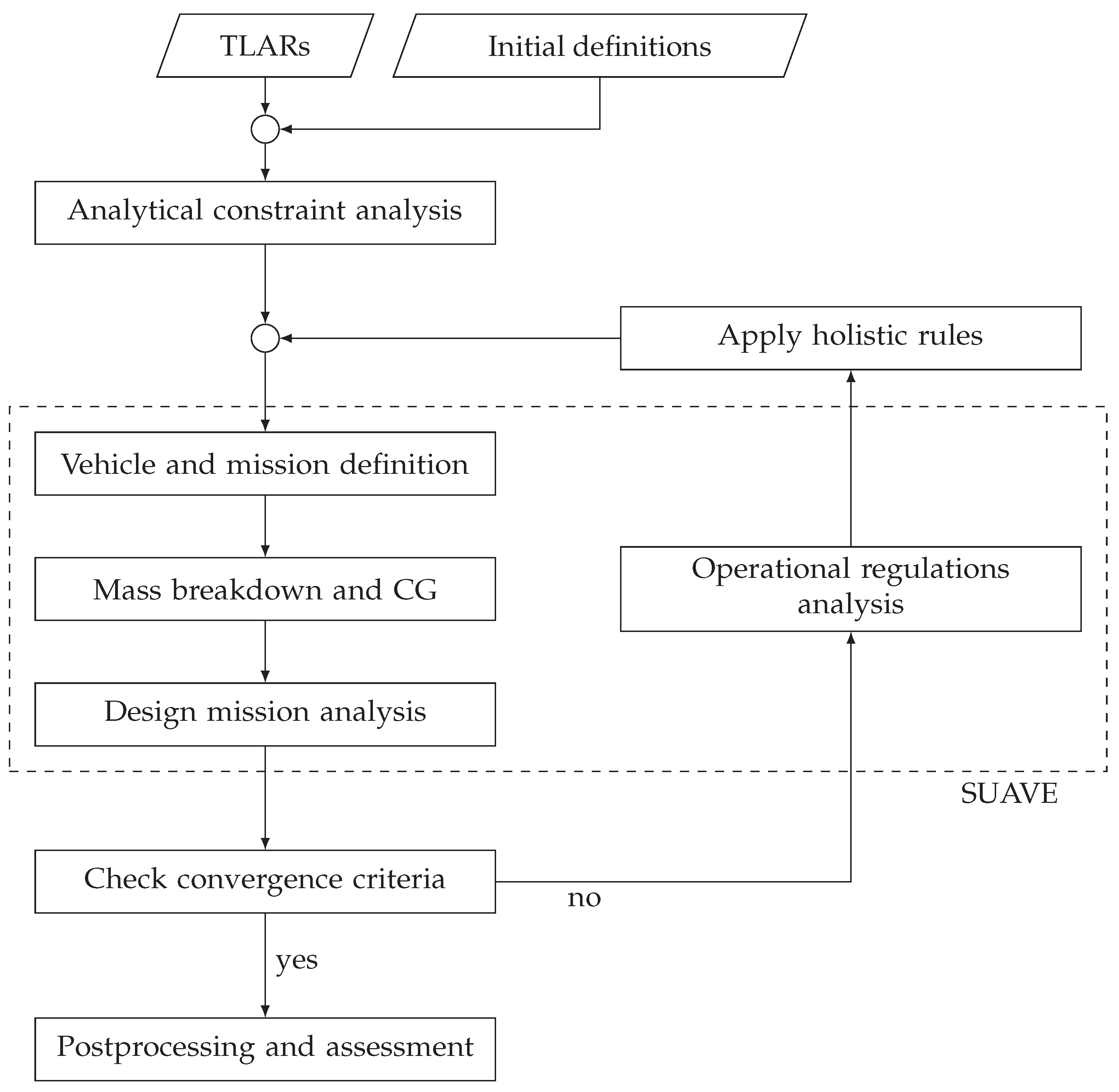
3.2. Numerical Analysis: Workflow with Enhanced SUAVE

The workflow and iterative sizing loop implemented in Python 3.9 for the overall aircraft design, implemented within the enhanced SUAVE framework (dashed box), adapted from Mangold et al. [12], is illustrated in Figure 2. The process began with the input of TLARs and initial definitions, which were fed into an initial analytical constraint analysis (see Section 3.1). The results of this analysis—namely, the design point defined by m 0 / S and P / m 0 —informed the vehicle and mission definition, where the aircraft was geometrically defined and the design mission was specified. Consequently, a mass breakdown and center-of-gravity (CG) were determined, followed by a mission analysis of the design mission. After these steps, the results were evaluated against convergence criteria. If these criteria were met, the process proceeded to postprocessing and assessment, finalizing the design (see Section 4). If not, the workflow diverted to a secondary loop consisting of an operational regulations mission analysis (see Section 3.2). The application of holistic design rules fed changes back into the vehicle and mission definition, and the process was reiterated until the design met all necessary criteria and requirements. This workflow systematically addressed the overall aircraft design process, ensuring compliance with certification specifications and operational regulations.
Numerical mission analysis in the enhanced SUAVE framework plays a critical role in sizing and optimizing hybrid electric propulsion architectures. At its core, this approach relies on a fully defined equation system for propulsion architectures (implemented in the energy network of SUAVE), which serves as the foundational basis for the analysis. By iteratively solving the complete set of energy network equations during the mission analysis (i.e., by solving the flight equations), the numerical analysis accounts for comprehensive, higher-fidelity models. This methodology captures the complex interdependencies between various components and enables a more detailed and realistic simulation of flight conditions. SUAVE employs a segment-based mission approach, allowing for flexible interventions to account for EMSs and failure scenarios (see Section 3.2.1 and Section 3.2.2).
In the SPPH architecture implemented in SUAVE by Mangold et al. [12], the distribution is mainly controlled by the throttles of the gas turbine ξ GT , EM1 ξ EM 1 , and EM2 ξ EM 2 . Therefore, the battery power is the result of the sum of the electric powers at PM (see Figure 1). This approach emerges through the solving procedure of the higher-fidelity energy network in SUAVE. Nevertheless, to admit compliance with the preliminary approach of not having an energy network already included in SUAVE, there needs to be slightly different variables.
To ensure that workflow and aircraft sizing issues did not arise, battery technology was improved, allowing all EMSs to function as intended. The improvement in battery performance was realized by scaling the Ragone plot, as described by Eisenhut et al. [64]. This approach highlighted the influence of EMS combined with the battery technology on overall system performance. Although the results yielded quantitative values, they were not necessarily indicative of an optimal aircraft design. Instead, the focus was on illustrating the interactions between hybrid electric propulsion components and operational constraints.
Table 1 summarizes an example implementation of an EMS, specifically, EMS1, by listing the throttle settings for each propulsion component across different flight segments relevant to the mission, which includes both the design mission and reserve phases. In this example, the gas turbine throttle ( ξ GT ) was set to 0.9 during both the climb and reserve climb segments and operated at idle during descent. For the cruise and reserve cruise segments, ( ξ GT ) was designated as ‘unknown’, reflecting the SUAVE mission analysis procedure, where certain mission segments included variables that needed to be solved during the analysis. For a detailed description of these mission segments, please refer to SUAVE [27,28].
The secondary electric motor (EM2) was operated at full throttle (1.0) during the climb, cruise, reserve climb, and reserve cruise segments but was turned off (0) during descent. In the configuration shown, the primary electric motor (EM1) was deactivated (0) throughout all flight segments, thereby neglecting the interaction between the two power paths and simplifying the analysis.
In contrast to the configuration depicted in Table 1, alternative EMS variants could be defined by varying the throttle settings for EM2. For clarity, the following variants were proposed:
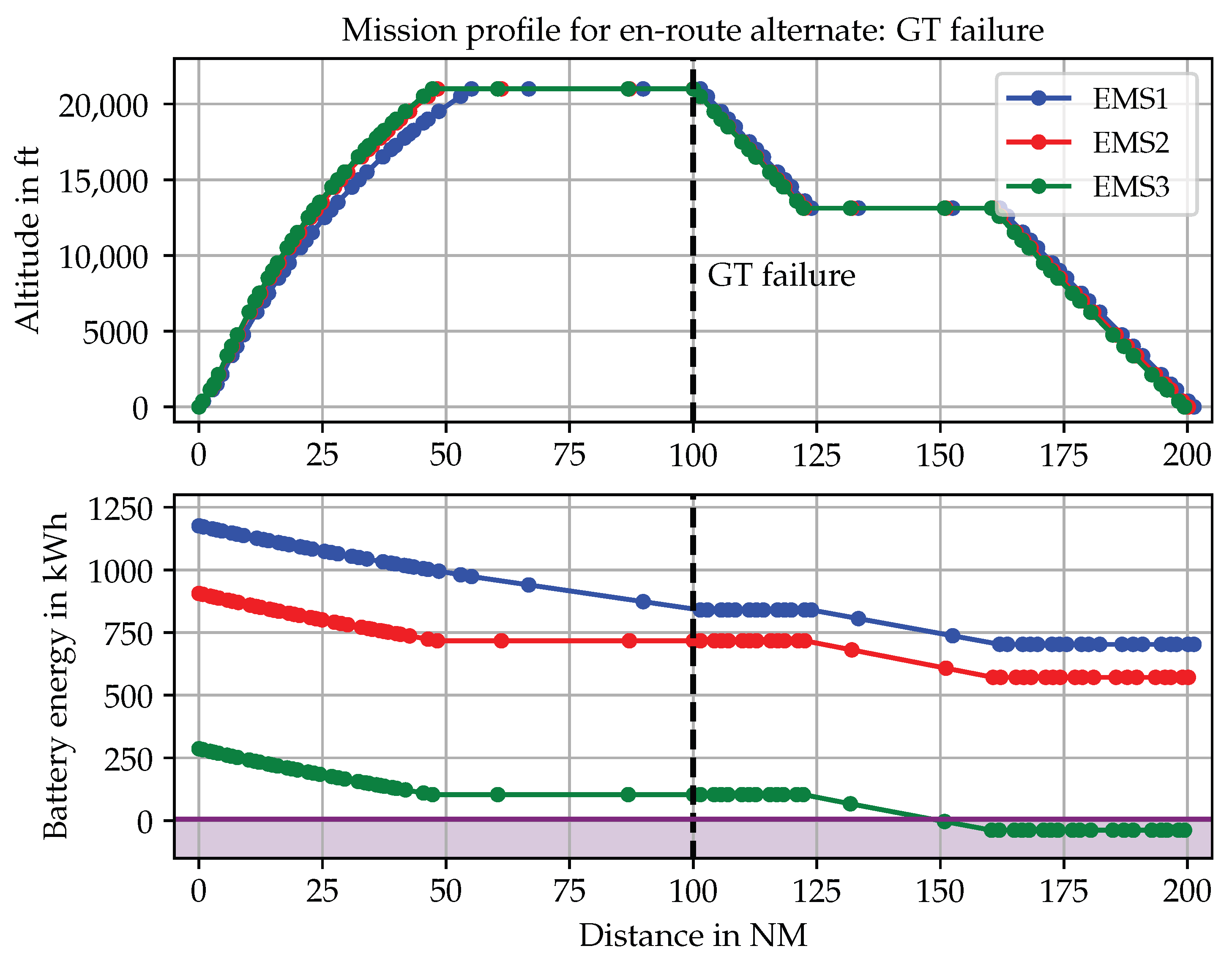
  • EMS1: The secondary electric motor (EM2) is powered by the battery in all flight segments except during descent.
  • EMS2: EM2 is powered by the battery in all flight segments except during cruise and descent.
  • EMS3: EM2 is powered by the battery only in the climb and reserve climb segments.
By adjusting the throttle settings for EM2, these strategies modifed the distribution of battery energy throughout the flight mission. Such variations can significantly influence both the sizing of the secondary energy carrier and the overall propulsion system performance (see Section 4).

3.2.1. Propulsion Architecture Adaptions for Failure Implementation

The adaptation of the energy network (i.e., the equation system of the propulsion architecture in SUAVE) to incorporate failure scenarios was achieved by introducing a failure flag within the SUAVE configuration setup (configs_setup). This configuration describes the current state of the aircraft (for example, whether the flaps are extended or the landing gear is extended).
In practical terms, this involved adding a tag labeled ’failure’ in the configuration. When set to true, the failure flag triggered adjustments within the energy network model (e.g., Equation (24)) that simulated the impact of a component or engine failure on power distribution and overall system performance. This mechanism allowed the model to account for reduced power availability and evaluate the resilience of the system under failure conditions, thereby enhancing the robustness of the design analysis.
For example, consider the following equation, which calculates the total power of all gas turbines, P GT , total , as a function of the power of a single gas turbine, P GT , the number of gas turbines, n GT , and the failure flag (where failure GT is equal to 1 when true and 0 when false):
P GT , total = P GT · n GT failure GT
This definition essentially represents the previously mentioned ( n 1 ) term in Section 2.3.2. Such a simple definition of a failure is possible because the equation system of the propulsion architecture is fully defined and implemented within the energy network in SUAVE. As noted for the preliminary aircraft design phase, a detailed energy network and explicit connections between components are often not yet available. Using SUAVE requires implementing the entire equation system of the propulsion architecture—including the number of individual components and their interconnections—which increases the fidelity of the preliminary design phase beyond a sketch or conceptual idea of the hybrid electric propulsion architecture. Consequently, the fully defined equation system allows for a comprehensive accounting of failure scenarios.
These definitions of failures in the numerical analysis with the enhanced SUAVE version were necessary for the operational regulations analysis in Section 3.2.2. Capturing the impact of failures on the power of the propulsion architectures was a key step toward developing a robust methodology for investigating the energy requirements under various failure conditions.

3.2.2. Operational Regulations Analysis

To assess the impact of operational regulations on hybrid electric propulsion architectures, a methodology must be implemented to evaluate how these additional requirements, beyond standard reserve policies, affect aircraft design, as summarized in Section 2.4. This analysis is crucial in the preliminary design phase for hybrid electric aircraft, ensuring compliance with stringent safety and performance standards mandated by aviation authorities [43]. One critical aspect is the ERA aerodrome requirement [43], which mandates that an aircraft must be capable of safely reaching an ERA aerodrome in the event of an engine failure. Hybrid electric propulsion architectures, however, introduce complexities due to the integration of multiple energy carriers, all of which must be considered when assessing the aircraft’s ability (energy constraint) to meet ERA criteria.
The ERA requirement under investigation considered a failure scenario—namely, the critical CLOT during cruise—after which the aircraft needed to fly 100 NM to safely reach an ERA aerodrome. Additionally, assuming that the departure aerodrome was equidistant, the failure was set to occur after 100 NM. To adopt a conservative approach, the aircraft was assumed to start at MTOM at the design point in the payload-range diagram. This meant that it operated at the design payload (full passenger capacity) and design fuel mass, with fully charged batteries at the start of the mission.
As part of the overall aircraft design process, an operational regulations analysis was incorporated, as illustrated in Figure 2. This analysis was based on the typical mission analysis framework of SUAVE, which numerically solves the flight equation for a predefined mission consisting of multiple segments. A mission segment in SUAVE represents a portion of the flight where certain variables remain constant, such as throttle setting and true airspeed (e.g., constant throttle constant speed) and All Engines Operating (AEO) or CLOT.
To determine whether a critical energy constraint arose, e.g., for the secondary energy carrier in the event of a primary power path failure (e.g., gas turbine failure), a new mission definition was required, as depicted in Section 2.2.2. The ERA aerodrome mission consisted of the following segments, which could include multiple SUAVE mission segments:
  • Climb, AEO: constant calibrated airspeed, constant throttle to cruise altitude
  • Cruise, AEO: constant true airspeed, constant altitude until 100 NM distance
  • Failure, i.e., CLOT
  • Descent/drift down, CLOT: constant calibrated airspeed, constant throttle (idle) to ceiling CLOT altitude
  • Cruise, CLOT: constant true airspeed, constant altitude
  • Descent, CLOT: constant calibrated airspeed, constant throttle (idle)
  • Landing, CLOT: constant true airspeed, constant angle, reaching a total distance of 200 NM
The results and assessment of the ERA analysis are presented in Section 4.2.

4. Results

In this section, the results of the analytical constraint and numerical analysis are presented based on the regional aircraft ATR 42 as a reference aircraft. The results are exemplified using a supplied shaft power ratio of Φ S , SLS = 0.2 , which corresponded to 20% battery power relative to the total power under normalized conditions. The analytical constraint analysis quantified the impact of failure cases and various EMS scenarios on overall performance, specifying the power requirements and enabling a clear determination of the CLOT condition and the necessary oversizing factor to maintain safe operation. In addition, an investigation of operational regulations for ERA aerodromes was conducted, with a particular focus on the CLOT ceiling and different EMS scenarios. This investigation evaluated the energy requirements of the secondary energy carrier under CLOT conditions, determining whether an energy sizing criterion for the secondary energy carrier was needed. Together, these results provide a comprehensive assessment of both the power constraints and the energy demands of the proposed hybrid electric propulsion architecture with dual-energy carriers.

4.1. Evaluating Power Requirements and Redundancy Under Failure Conditions

A key challenge in the preliminary design of hybrid electric aircraft is determining the necessary power loading to ensure safe operation under failure conditions. Addressing this question early in the design process is critical as it directly influences component sizing and the overall feasibility of the propulsion architecture. The analytical equations derived in Section 3.1 provided a structured approach to classifying failures and assessing the impact of EMS power requirements, ultimately leading to the identification of the CLOT and a meaningful design point.
The hybrid electric propulsion architecture featured symmetrical components on the left and right wings. Consequently, Figure 1 is mirrored horizontally, meaning that all components are present in duplicate. Due to the redundancy of the components (e.g., two gas turbines and two batteries), different failure scenarios led to different power availability conditions. If a gas turbine failed ( Φ GT = 0.4 , see Equation (18)), both batteries remained fully operational, providing their complete power output. In contrast, if one battery failed ( Φ = 0.1 , see Equation (17)), both gas turbines remained functional, but only half of the total battery power was available.
Through this initial analytical assessment (see Section 3.1.1), the CLOT could be evaluated. In this case, the gas turbine failure represented the most critical failure mode, resulting in an oversizing factor f OS of 1.667, compared to 2 for a conventional design with only two gas turbin, representing a reduction of 16.7 %. However, this purely analytical failure assessment has limitations compared to the approach that incorporates the EMS. The analysis in Section 3.1.1 considers only the ratio of available power after a failure, which can be easily determined under SLS and normalized conditions. However, Equation (16) does not account for the distinction between the primary and secondary power paths, making it difficult to accurately determine Φ under the influence of the power lapse ratio. As a result, Equation (16) is not universally valid as it does not differentiate between the two power paths.
In contrast, the general formulation of f OS using Φ from Equation (14) remains valid in all cases. However, determining Φ under the influence of the power lapse ratio is more complex as this requires a detailed consideration of power degradation effects under varying operating conditions. This aspect is addressed in the methodology of EMS consideration in Section 3.1.2.
Figure 3 presents the results of the constraint analysis incorporating the EMS methodology (see Section 3.1.2), represented by the sizing chart for the primary power source (one gas turbine). The plot illustrates the relationship between power loading (in W / kg ) and wing loading (in kg / m 2 ) under various constraints, including take-off and landing field length constraints (green and orange lines) and different OEI ceiling scenarios. The take-off and landing field length constraints are based on the ATR 42 and are included for context but are not the primary focus of this research.
The OEI ceiling conditions accounted for either a gas turbine failure or a battery failure, again using Φ S , SLS = 0.2 . In the case of a gas turbine failure, different levels of battery power support ξ BAT (0%, 50%, and 100%) were considered, representing variations in the EMS. The OEI ceiling constraints shown in Figure 3 were derived using Equation (21), which integrated the EMS into the analysis.
The boundary conditions and input parameters for the OEI ceiling equations were based on values comparable to those of an ATR 42: a horizontal speed of v = 100   m / s with a vertical speed of v v = 150   ft / min at a ceiling altitude of 13125 ft. The lift-to-drag ratio was L / D = 15.9 and the efficiency of both propellers was set to η P = 0.85 . The power lapse ratio of α = 0.8 was calculated according to Gudmundsson [21] and the mass ratio was set to β = 0.95 . For simplification, other parameters, such as the efficiency of the PM, were assumed to be 100%.
The solid, dashed, and dotted purple lines represent the OEI ceiling constraints for a gas turbine failure with different levels of battery support, demonstrating how the overall power requirement decreased as battery power contribution increased (from the dashed to the solid line). Consequently, the shaded purple region highlights areas where power loading requirements exceeded feasible design limits, emphasizing the impact of EMSs on aircraft sizing. Additionally, the blue line represents a battery failure scenario that was the least critical failure case.
One key observation is that for ξ BAT = 50 % , the constraint was not positioned symmetrically between the 0% and 100% constraints. This discrepancy arose due to the different power lapse ratios between the gas turbine and the battery. The primary power path, which relied on a combustion engine, exhibited a different efficiency behavior under altitude and atmospheric variations compared to the battery. As a result, the transition between EMS variations did not follow a linear trend.
At first glance, the scenario where the gas turbine failed without battery support (0% BAT, dashed purple line) appeared to be the most critical case, leading to the highest power requirement. However, since this case assumed no battery support, the propulsion architecture effectively behaved like a conventional system with only two gas turbines. Therefore, this case also corresponded to the power loading requirement of an ATR 42. Looking at the lower edge of the shaded purple region, the case of a gas turbine failure with 100% battery support (solid purple line) represented the minimum power loading requirement of 60 W/kg. This demonstrates the advantage of hybrid electric propulsion architectures with dual-energy carriers and two power paths. Specifically, for the same constraint, the required power loading was reduced by 37.5 % for Φ S , SLS = 0.2 . This reduction is particularly noteworthy because it did not scale linearly with Φ S , SLS due to the fact that the electrified secondary power path was not affected by atmospheric conditions (i.e., α BAT = 1 ).
To identify a meaningful design point, the results in Figure 3 indicate that a gas turbine failure with a specific level of battery support (e.g., ξ BAT = 20 % , not included in the figure) aligns with three overlapping constraints: take-off and landing field length and ceiling OEI (shifting the solid purple line upwards). This convergence suggests a potentially optimal design point that balances power distribution between the gas turbine and the battery while ensuring compliance with multiple operational constraints. However, this raises the question of whether it is reasonable to use only 20% of the available battery power or whether it would be more effective to reduce Φ S , SLS . Additionally, energy constraints could shift the design priorities since an energy constraint may have a more significant impact on overall aircraft performance than simply installing more power. Furthermore, other constraints not included in this sizing chart may also influence the final design decision.
When considering the overall aircraft design, including the design mission in combination with battery technology limitations and assessments, the apparent optimal design point could shift. In particular, integrating ERA requirements into the mission analysis introduced additional energy constraints, necessitating a more comprehensive evaluation of energy carriers. The interaction between these factors highlights the need for a holistic approach to overall aircraft design, particularly for hybrid electric propulsion architectures, where constraint analysis, mission feasibility, and regulatory compliance must be jointly considered.
Hybrid electric propulsion architectures inherently provide increased redundancy compared to conventional systems, not only due to the presence of additional components, such as a secondary energy carrier, but also due to fundamental differences in power lapse behavior. Consequently, this enables a downsizing of the gas turbine while maintaining overall performance and compliance with certification constraints. This synergy between multiple power and energy sources provides additional design flexibility, ensuring that hybrid electric aircraft can achieve performance targets while minimizing excess installed power and mass.
Furthermore, the first research question was effectively resolved by the proposed methodology, which demonstrated that the determination of power loading for hybrid electric propulsion architectures—including the integration of additional variables arising from multiple energy carriers—could be systematically addressed.

4.2. Impact of Operational Regulations on Energy: En-Route Alternate with CLOT Ceiling

Through integration with the higher-fidelity numerical analysis in SUAVE, as outlined in Section 3.2, operational regulations could also be evaluated through mission analysis. The results, as previously stated, are presented for an exemplary supplied shaft power ratio of Φ S , SLS = 0.2 . Based on the analytical constraint analysis and failure identification, the CLOT condition for this Φ S , SLS corresponded to a gas turbine failure. Consequently, in the operational analysis, a gas turbine failure was simulated to account for the CLOT condition.
As discussed earlier, the energy demand of the aircraft, particularly for the secondary energy carrier, was highly dependent on the EMS. This dependence became evident in the operational regulations analysis, where the ceiling CLOT requirement was examined in relation to the EMS used during the design mission of the aircraft. Depending on the EMS, we evaluated the battery’s energy requirements as the secondary energy carrier under critical scenarios.
Figure 4 presents the mission profile analysis for a gas turbine failure scenario, assessing the operational feasibility of ERA regulations. The results depict altitude and battery energy use over a 200 NM mission, as described in Section 3.2.2. The mission consisted of an initial climb and cruise phase, during which all systems operated nominally until 100 NM was reached. At this point, a gas turbine failure occurred during cruise, followed by a CLOT ceiling segment, after which the aircraft proceeded to descent and landed at the ERA aerodrome.
The upper plot of Figure 4 illustrates the aircraft’s altitude profile (in ft ) as a function of distance (in NM ). The different EMSs (EMS1, EMS2, EMS3) resulted in slight variations in flight paths due to the influence of EMS on the design mission sizing procedure, which, in turn, affected overall aircraft performance (see Table 2).
The bottom plot shows battery energy consumption, measured in kWh , over the flight distance, highlighting differences in battery utilization across EMS variations. Decreasing battery energy indicated that propulsion power was being supplied by the battery. After the gas turbine failure, the EMS remained identical across all three variations: during drift-down, the battery was not used; at the CLOT ceiling, the battery provided power; and during descent and landing, the battery was also not used. The bottom plot could alternatively be displayed using the battery’s SoC, which would yield a similar curve, but all EMS variations would begin at 95% SoC (as per the battery sizing criteria), thereby omitting the total battery capacity representation.
The results shown in Figure 4 highlight a critical scenario regarding the battery energy requirement—specifically, the occurrence of a negative SoC (indicated by the purple shaded area)—when the battery was primarily utilized during the climb phases of the design mission (EMS3, see Table 1). As illustrated in Figure 4, during the ERA mission following a gas turbine failure, all three EMSs required roughly the same battery energy. This observation suggests that the negative SoC at the end of the mission was due to the relatively low total battery energy available with EMS3. Furthermore, as shown in Table 2, the battery mass for the aircraft designed with EMS3 was lower compared to those designed with EMS1 and EMS2, indicating reduced battery utilization during the design mission.
However, a negative SoC was not feasible, as this indicated that the aircraft would not meet required energy reserves. To resolve this issue, a new convergence criterion needed to be introduced, ensuring that no operational scenario would lead to a negative battery SoC. Additionally, a holistic rule needed to be integrated into the design process, systematically accounting for energy constraints and regulatory requirements. This framework guaranteed that the battery retained sufficient charge throughout the entire mission, thereby maintaining compliance and ensuring overall operational safety.
Limiting the operation of the battery to only specific mission segments (EMS3) resulted in a sizing criterion based on power requirements, implying that the battery had a relatively high mass-specific power compared to its mass-specific energy, as indicated by the Ragone plot. In contrast, the batteries sized under EMS1 and EMS2 were characterized by relatively high mass-specific energy, corresponding to an energy-based sizing criterion.
If a gas turbine failure occurred during cruise, the available battery capacity needed to not only support the climb phase but also sustain subsequent cruise segments after the failure until the alternative airport was reached, as incorporated into the analytical constraint analysis in Section 4.1 to allow for a downsized gas turbine. This scenario and the operational mission analysis demonstrated that the choice of EMS during the design phase significantly influences the feasibility of meeting ERA aerodrome requirements and operational regulations in general.
The analysis highlights the importance of establishing robust energy sizing criteria for the secondary energy carrier and its impact on preliminary aircraft design. A well-balanced EMS is required to ensure compliance with ERA regulations while preventing excessive battery depletion. Moreover, operational regulations directly affect the sizing of the secondary energy carrier. By integrating a higher-fidelity numerical analysis within SUAVE, the operational feasibility of hybrid electric propulsion architectures can be assessed more accurately, thereby helping to define appropriate energy sizing criteria and ensuring robust aircraft performance under failure conditions. This mission profile thus demonstrates the interaction between operational regulations, EMS, and aircraft design. Hybrid electric propulsion architectures must account for both power and energy constraints as an insufficiently sized battery could compromise mission feasibility following a failure.
Additionally, for the advanced battery technology, the results shown in Table 2 from the aircraft design loop (excluding feedback from the operational regulations analysis) indicate that EMS1 yielded the lowest trip and design fuel consumption, suggesting that it may be the most fuel-efficient configuration. However, EMS1 also resulted in the highest MTOM, implying increased capital and direct operating costs. In other words, without a clearly defined figure of merit, it is challenging to identify the optimal aircraft design. Moreover, considering the operational regulations and ERA mission requirements, it is critical to note that if the secondary energy carrier is not used extensively during the design mission but is included in the constraint analysis to downsize the primary power source, a new (energy) sizing criterion for the secondary energy carrier may be necessary.
Overall, the results highlight a critical scenario regarding operational regulations when the battery is used primarily during the climb phases in the design mission (EMS3). If the battery is depleted too early because of a CLOT, the aircraft may not have sufficient reserves for sustained flight to the ERA aerodrome. Importantly, this analysis effectively addressed the second research question by demonstrating that operational regulations have a substantial impact on the secondary energy carrier. This finding underscores the need to rigorously evaluate operational regulations during the preliminary aircraft design process as they may lead to the development of new battery sizing criteria to ensure adequate energy reserves under failure conditions.
Furthermore, it should be noted that the battery is not only used during the design mission but also plays a critical role in the ERA mission. In the event of a GT failure, the battery must compensate for the lost power—a core aspect of EMS3. Although increasing the size of the primary power source (i.e., the GT) could theoretically mitigate this issue, such an approach would undermine the original purpose of EMS3: reducing the power loading of the GT through battery support. This highlights a key insight: different EMSs must be integrated from the outset of the design process to fully account for their implications. Moreover, this example illustrates how an initially promising concept aimed at lowering power loading can trigger snowball effects throughout the aircraft design, ultimately compromising overall performance when all operational and failure considerations are addressed.

5. Conclusions

The integration of a secondary energy carrier—specifically, batteries—into hybrid electric aircraft designs to enhance environmental sustainability and reduce emissions was examined in this study. By hybridizing the propulsion architecture, this research introduced new variables and synergies that extend beyond conventional design considerations, particularly in terms of failure classification and energy management strategies. Traditional one-engine-inoperative (OEI) scenarios were found to be insufficient for capturing the complexity of hybrid electric propulsion architectures, necessitating a more differentiated approach to assess propulsion failures and identify the critical loss of thrust (CLOT).
To address these challenges, the methodology combined an analytical constraint analysis for power requirements with a higher-fidelity numerical design loop implemented in SUAVE for energy requirements. This approach allowed for an in-depth evaluation based on the supplied shaft power ratio between primary and secondary energy carriers and facilitated a thorough classification of failure scenarios. The resulting analytical sizing charts demonstrated that while a secondary energy carrier increases system redundancy—thus reducing the need for excessive oversizing of the primary power source—the numerical analysis of operational regulations revealed a significant influence on the sizing of the battery, particularly when its use is limited to specific mission segments, i.e., the power requirement sizes the battery.
Importantly, this study aimed to answer two research questions: (1) How can a meaningful power loading be determined for hybrid electric propulsion architectures with two energy carriers? (2) What is the effect of a failure during cruise on the aircraft, especially regarding the energy requirement of the secondary energy carrier? The findings demonstrate that both research questions were successfully addressed.
The integration of analytical and numerical methods in the proposed framework successfully bridges the gap between certification specifications and operational regulations. This unified approach not only highlights the critical impact of energy management strategies and CLOT on aircraft design and performance but also underscores the importance of incorporating these considerations early in the design process.
Future research will build on these findings by investigating additional operational regulations (such as take-off alternates), incorporating higher-fidelity take-off field length calculation models, and analyzing the effects of battery turnaround procedures on aircraft utilization. These efforts are expected to further refine the interactions between aircraft design, operational regulations, and energy management strategies, ultimately contributing to more applicable aircraft designs with hybrid electric propulsion architectures.

Author Contributions

Conceptualization, J.M.; methodology, J.M.; writing—original draft preparation, J.M.; writing—review and editing, J.M. and A.S.; supervision, A.S.; All authors have read and agreed to the published version of the manuscript.

Funding

This research was funded by Deutsche Forschungsgemeinschaft (DFG, German Research Foundation) Project ID 498601949—TRR 364.

Data Availability Statement

The datasets presented in this article are not readily available as the enhanced SUAVE workflow is part of an ongoing study. Requests to access the datasets should be directed to the corresponding author.

Conflicts of Interest

The authors declare no conflicts of interest.

Nomenclature

Abbreviations 
AEOAll Engines Operating
CLOTCritical Loss of Thrust
EMSEnergy Management Strategy
ERAEn-Route Alternate
ISAInternational Standard Atmosphere
MTOMMaximum Take-Off Mass
OEIOne-Engine-Inoperative
SAFSustainable Aviation Fuel
SLSSea-Level Static
SoCState of Charge
SPPHSerial-Parallel Partial-Hybrid
TLARsTop-Level Aircraft Requirements
Symbols
α Power lapse ratio-
β Mass ratio-
η Efficiency-
Φ Supplied power ratio-
ϕ Power split-
Φ S Supplied shaft power ratio-
Ψ D Distribution ratio-
ξ Throttle-
EEnergy J
fFactor-
gGravitational acceleration constant m   s 2
HHybridization factor-
mMass k g
m 0 / S Wing loading k g   m 2
nNumber-
P / m 0 Power loading W kg 1
PPower W
TThrust N
vVelocity m   s 1
L/DLift-to-drag ratio-
Subscripts
BATBattery
convConventional
EEnergy
E1Primary electric
E2Secondary electric
EM1Primary electric motor
EM2Secondary electric motor
engEngine
F                        Fuel
GBGear box
GTGas turbine
iConstraint
jType of power source
kSource with a failure
OSOver sizing
PPower
P1Primary propeller
P2Secondary propeller
PMPower management
SShaft
S1Primary shaft
S2Secondary shaft
supSupplied
vVertical

References

  1. European Commission and Directorate-General for Research and Innovation. Fly the Green Deal—Europe’s Vision for Sustainable Aviation; Publications Office of the European Union: Luxembourg, 2022. [Google Scholar] [CrossRef]
  2. European Commission. The European Green Deal COM(2019) 640. Available online: https://eur-lex.europa.eu/resource.html?uri=cellar:b828d165-1c22-11ea-8c1f-01aa75ed71a1.0002.02/DOC_1&format=PDF (accessed on 18 July 2024).
  3. European Commission. Directorate General for Research and Innovation; European Commission. Directorate General for Mobility and Transport. In Flightpath 2050: Europe’s Vision for Aviation: Maintaining Global Leadership and Serving Society’s Needs; Publications Office: Luxembourg, 2011. [Google Scholar]
  4. Geiß, I. Sizing of the Series Hybrid-Electric Propulsion System of General Aviation Aircraft. Ph.D. Thesis, University of Stuttgart, Stuttgart, Germany, 2020. [Google Scholar]
  5. Mangold, J.; Brenner, F.; Moebs, N.; Strohmayer, A. Aircraft Design Implications of Alternative Fuels for Future Hybrid-Electric Regional Aircraft Configurations. In Proceedings of the 9th European Conference for Aerospace Sciences, Lille, France, 27 June–1 July 2022. [Google Scholar] [CrossRef]
  6. Geiß, I.; Voit-Nitschmann, R. Sizing of the Energy Storage System of Hybrid-Electric Aircraft in General Aviation. CEAS Aeronaut. J. 2017, 8, 53–65. [Google Scholar] [CrossRef]
  7. Hepperle, M. Electric Flight—Potential and Limitations. In Proceedings of the Energy Efficient Technologies and Concepts of Operation, Lisbon, Portugal, 22–24 October 2012. [Google Scholar]
  8. Air Transport Action Group. Waypoint 2050, Second Edition. 2021. Available online: https://aviationbenefits.org/media/167417/w2050_v2021_27sept_full.pdf (accessed on 8 October 2024).
  9. Braun-Unkhoff, M.; Riedel, U. Alternative fuels in aviation. CEAS Aeronaut. J. 2014, 6, 83–93. [Google Scholar] [CrossRef]
  10. Heyne, J.; Rauch, B.; Clercq, P.L.; Colket, M. Sustainable aviation fuel prescreening tools and procedures. Fuel 2021, 290, 120004. [Google Scholar] [CrossRef]
  11. Moebs, N.; Eisenhut, D.; Windels, E.; van der Pols, J.; Strohmayer, A. Adaptive Initial Sizing Method and Safety Assessment for Hybrid-Electric Regional Aircraft. Aerospace 2022, 9, 150. [Google Scholar] [CrossRef]
  12. Mangold, J.; Eisenhut, D.; Brenner, F.; Moebs, N.; Strohmayer, A. Preliminary Hybrid-Electric Aircraft Design with Advancements on the Open-Source Tool SUAVE. J. Phys. Conf. Ser. 2023, 2526, 012022. [Google Scholar] [CrossRef]
  13. de Vries, R.; Brown, M.; Vos, R. Preliminary Sizing Method for Hybrid-Electric Distributed-Propulsion Aircraft. J. Aircr. 2019, 56, 2172–2188. [Google Scholar] [CrossRef]
  14. Bovet, L. Conceptual design optimization of Hybrid-Electric Regional Aircraft using SPPH architecture. In Proceedings of the Aerospace Europe Conference -EUCASS-CEAS-2023, Lausanne, Switzerland, 9–13 July 2023. [Google Scholar] [CrossRef]
  15. Kuśmierek, A.; Galiński, C.; Stalewski, W. Review of the hybrid gas - electric aircraft propulsion systems versus alternative systems. Prog. Aerosp. Sci. 2023, 141, 100925. [Google Scholar] [CrossRef]
  16. Brelje, B.J.; Martins, J.R. Electric, hybrid, and turboelectric fixed-wing aircraft: A review of concepts, models, and design approaches. Prog. Aerosp. Sci. 2019, 104, 1–19. [Google Scholar] [CrossRef]
  17. Isikveren, A.; Kaiser, S.; Pornet, C.; Vratny, P. Pre-design strategies and sizing techniques for dual-energy aircraft. Aircr. Eng. Aerosp. Technol. 2014, 86, 525–542. [Google Scholar] [CrossRef]
  18. Finger, D.F.; Braun, C.; Bil, C. An Initial Sizing Methodology for Hybrid-Electric Light Aircraft. In Proceedings of the 2018 Aviation Technology, Integration, and Operations Conference, Atlanta, GA, USA, 25–29 June 2018; American Institute of Aeronautics and Astronautics: Reston, VA, USA, 2018. [Google Scholar] [CrossRef]
  19. Finger, D.F.; de Vries, R.; Vos, R.; Braun, C.; Bil, C. A Comparison of Hybrid-Electric Aircraft Sizing Methods. In Proceedings of the AIAA Scitech 2020 Forum, Orlando, FL, USA, 6–10 January 2020; American Institute of Aeronautics and Astronautics: Reston, VA, USA, 2020. [Google Scholar] [CrossRef]
  20. Raymer, D. Aircraft Design: A Conceptual Approach, 6th ed.; American Institute of Aeronautics and Astronautics, Inc.: Reston, VA, USA, 2018. [Google Scholar] [CrossRef]
  21. Gudmundsson, S. General Aviation Aircraft Design; Elsevier Science & Technology: Amsterdam, The Netherlands, 2014. [Google Scholar]
  22. Roskam, J. Airplane Design Part I–VIII; Design Analysis & Research: Lawrence, KS, USA, 1985. [Google Scholar]
  23. Nam, T.; Soban, D.; Mavris, D. Power Based Sizing Method for Aircraft Consuming Unconventional Energy. In Proceedings of the 43rd AIAA Aerospace Sciences Meeting and Exhibit, Reno, NV, USA, 10–13 January 2005; American Institute of Aeronautics and Astronautics: Reston, VA, USA, 2005. [Google Scholar] [CrossRef]
  24. de Vries, R.; Hoogreef, M.F.M.; Vos, R. Range Equation for Hybrid-Electric Aircraft with Constant Power Split. J. Aircr. 2020, 57, 552–557. [Google Scholar] [CrossRef]
  25. Joksimović, A.; Carbonneau, X.; Crabé, C.; Benichou, E. Generalised Methodology for Sizing of Air Vehicles with Hybrid-Electric Propulsion. In Proceedings of the STO-MP-AVT-323, Trondheim, Norway, 7–11 October 2019. [Google Scholar]
  26. Torenbeek, E. Synthesis of Subsonic Airplane Design; Springer: Dordrecht, The Netherlands, 1982. [Google Scholar] [CrossRef]
  27. MacDonald, T.; Clarke, M.; Botero, E.M.; Vegh, J.M.; Alonso, J.J. SUAVE: An Open-Source Environment Enabling Multi-Fidelity Vehicle Optimization. In Proceedings of the 18th AIAA/ISSMO Multidisciplinary Analysis and Optimization Conference, Denver, CO, USA, 5–9 June 2017; American Institute of Aeronautics and Astronautics: Reston, VA, USA, 2017. [Google Scholar] [CrossRef]
  28. Botero, E.M.; Wendorff, A.; MacDonald, T.; Variyar, A.; Vegh, J.M.; Lukaczyk, T.W.; Alonso, J.J.; Orra, T.H.; Ilario da Silva, C. SUAVE: An Open-Source Environment for Conceptual Vehicle Design and Optimization. In Proceedings of the 54th AIAA Aerospace Sciences Meeting, San Diego, CA, USA, 4–8 January 2016; American Institute of Aeronautics and Astronautics: Reston, VA, USA, 2016. [Google Scholar] [CrossRef]
  29. Karpuk, S.; Mosca, V.; Liu, C.; Elham, A. Development of a Multi-fidelity Design, Analysis, and Optimization Environment for Future Transport Aircraft. In Proceedings of the AIAA SCITECH 2022 Forum, San Diego, CA, USA, 3–7 January 2022; American Institute of Aeronautics and Astronautics: Reston, VA, USA, 2022. [Google Scholar] [CrossRef]
  30. Ma, Y.; Karpuk, S.; Elham, A. Conceptual design and comparative study of strut-braced wing and twin-fuselage aircraft configurations with ultra-high aspect ratio wings. Aerosp. Sci. Technol. 2022, 121, 107395. [Google Scholar] [CrossRef]
  31. Chuck, C.J.; Donnelly, J. The compatibility of potential bioderived fuels with Jet A-1 aviation kerosene. Appl. Energy 2014, 118, 83–91. [Google Scholar] [CrossRef]
  32. Coordinating Research Council. Handbook of Aviation Fuel Properties; CRC Report No. 530; Coordinating Research Council: Atlanta, GA, USA, 1983. [Google Scholar]
  33. Budde-Meiwes, H.; Drillkens, J.; Lunz, B.; Muennix, J.; Rothgang, S.; Kowal, J.; Sauer, D.U. A review of current automotive battery technology and future prospects. Proc. Inst. Mech. Eng. Part D J. Automob. Eng. 2013, 227, 761–776. [Google Scholar] [CrossRef]
  34. Farhad, S.; Nazari, A. Introducing the energy efficiency map of lithium-ion batteries. Int. J. Energy Res. 2018, 43, 931–944. [Google Scholar] [CrossRef]
  35. Saxon, A.; Yang, C.; Santhanagopalan, S.; Keyser, M.; Colclasure, A. Li-Ion Battery Thermal Characterization for Thermal Management Design. Batteries 2024, 10, 136. [Google Scholar] [CrossRef]
  36. Anker, M.A.; Hartmann, C.; Nøland, J.K. Feasibility of Battery-Powered Propulsion Systems for All-Electric Short-Haul Commuter Aircraft. IEEE Access. 2025, 13, 32260–32275. [Google Scholar] [CrossRef]
  37. Hu, J.; Booker, J. Preliminary Sizing of Electric-Propulsion Powertrains for Concept Aircraft Designs. Designs 2022, 6, 94. [Google Scholar] [CrossRef]
  38. Quillet, D.; Boulanger, V.; Rancourt, D.; Freer, R.; Bertrand, P. Parallel Hybrid-Electric Powertrain Sizing on Regional Turboprop Aircraft with Consideration for Certification Performance Requirements. In Proceedings of the AIAA AVIATION 2021 FORUM, Virtual, 2–6 August 2021; American Institute of Aeronautics and Astronautics: Reston, VA, USA, 2021. [Google Scholar] [CrossRef]
  39. Hoelzen, J.; Liu, Y.; Bensmann, B.; Winnefeld, C.; Elham, A.; Friedrichs, J.; Hanke-Rauschenbach, R. Conceptual Design of Operation Strategies for Hybrid Electric Aircraft. Energies 2018, 11, 217. [Google Scholar] [CrossRef]
  40. de Vries, R. Hybrid-Electric Aircraft with Over-the-Wing Distributed Propulsion: Aerodynamic Performance and Conceptual Design. Ph.D. Thesis, Delft University of Technology, Delft, The Netherlands, 2022. [Google Scholar]
  41. Pinto Leite, J.P.S.; Voskuijl, M. Optimal energy management for hybrid-electric aircraft. Aircr. Eng. Aerosp. Technol. 2020, 92, 851–861. [Google Scholar] [CrossRef]
  42. Quillet, D.; Boulanger, V.; Rancourt, D. Off-Design Performance Analysis of a Parallel Hybrid Electric Regional Turboprop Aircraft. J. Aircr. 2023, 60, 1728–1738. [Google Scholar] [CrossRef]
  43. European Union Aviation Safety Agency. Easy Access Rules for Air Operations (Regulation (EU) No 965/2012) Revision 21, September 2023, 2023. Available online: https://www.easa.europa.eu/en/document-library/easy-access-rules/easy-access-rules-air-operations-regulation-eu-no-9652012 (accessed on 18 July 2024).
  44. Jackson, P. (Ed.) Jane’s All the World’s Aircraft: Development & Production 2017–2018; IHS Global Limited: London, UK, 2017. [Google Scholar]
  45. Quillet, D.; Boulanger, V.; Rancourt, D.; Freer, R.; Bertrand, P. Impact of OEI requirement on parallel hybrid electric turboprop regional aircraft optimization. Aircr. Eng. Aerosp. Technol. 2022, 95, 276–283. [Google Scholar] [CrossRef]
  46. Boggero, L.; Fioriti, M.; Corpino, S. Development of a new conceptual design methodology for parallel hybrid aircraft. Proc. Inst. Mech. Eng. Part G J. Aerosp. Eng. 2017, 233, 1047–1058. [Google Scholar] [CrossRef]
  47. Finger, D.F.; Braun, C.; Bil, C. Impact of Engine Failure Constraints on the Initial Sizing of Hybrid-Electric GA Aircraft. In Proceedings of the AIAA Scitech 2019 Forum, San Diego, CA, USA, 7–11 January 2019; American Institute of Aeronautics and Astronautics: Reston, VA, USA, 2019. [Google Scholar] [CrossRef]
  48. Loftin, L. Subsonic aircraft: Evolution and the matching of size to performance. In National Aeronauticsand Space Administration, Reference Publication 1060; NASA: Hampton, VA, USA, 1980. [Google Scholar]
  49. Mattingly, J.D.; Heiser, W.H.; Pratt, D.T. Aircraft Engine Design, 2nd ed.; American Institute of Aeronautics and Astronautics: Reston, VA, USA, 2002. [Google Scholar] [CrossRef]
  50. European Aviation Safety Agency. Certification Specifications and Acceptable Means of Compliance for Large Aeroplanes (CS-25), Amendment 28; European Aviation Safety Agency: Cologne, Germany, 2023.
  51. Nam, T.; Soban, D.; Mavris, D. A Generalized Aircraft Sizing Method and Application to Electric Aircraft. In Proceedings of the 3rd International Energy Conversion Engineering Conference, San Francisco, CA, USA, 15–18 August 2005; American Institute of Aeronautics and Astronautics: Reston, VA, USA, 2005. [Google Scholar] [CrossRef]
  52. Finger, D.F.; Bil, C.; Braun, C. Initial Sizing Methodology for Hybrid-Electric General Aviation Aircraft. J. Aircr. 2019, 57, 245–255. [Google Scholar] [CrossRef]
  53. Finger, D.F.; de Vries, R.; Vos, R.; Braun, C.; Bil, C. Cross-Validation of Hybrid-Electric Aircraft Sizing Methods. J. Aircr. 2022, 59, 742–760. [Google Scholar] [CrossRef]
  54. de Vries, R.; Brown, M.T.; Vos, R. A Preliminary Sizing Method for Hybrid-Electric Aircraft Including Aero-Propulsive Interaction Effects. In Proceedings of the 2018 Aviation Technology, Integration, and Operations Conference, Atlanta, GA, USA, 25–29 June 2018; American Institute of Aeronautics and Astronautics: Reston, VA, USA, 2018. [Google Scholar] [CrossRef]
  55. Finger, D.F.; Götten, F.; Braun, C.; Bil, C. Mass, primary energy, and cost: The impact of optimization objectives on the initial sizing of hybrid-electric general aviation aircraft. CEAS Aeronaut. J. 2020, 11, 713–730. [Google Scholar] [CrossRef]
  56. European Aviation Safety Agency. Certification Specifications for Normal-Category Aeroplanes (CS-23) and Acceptable Means of Compliance and Guidance Material to the Certification Specifications for Normal-CategoryAeroplanes (AMC & GM to CS-23), CS-23 Amendment 6/AMC & GM to CS-23 Issue 4; European Aviation Safety Agency: Cologne, Germany, 2023.
  57. Sgueglia, A.; Schmollgruber, P.; Bartoli, N.; Benard, E.; Morlier, J.; Jasa, J.; Martins, J.R.R.A.; Hwang, J.T.; Gray, J.S. Multidisciplinary Design Optimization Framework with Coupled Derivative Computation for Hybrid Aircraft. J. Aircr. 2020, 57, 715–729. [Google Scholar] [CrossRef]
  58. Steiner, H.J.; Vratny, P.C.; Gologan, C.; Wieczorek, K.; Isikveren, A.T.; Hornung, M. Optimum number of engines for transport aircraft employing electrically powered distributed propulsion. CEAS Aeronaut. J. 2014, 5, 157–170. [Google Scholar] [CrossRef]
  59. Marciello, V.; Orefice, F.; Nicolosi, F.; Ciliberti, D.; Della Vecchia, P. Design of hybrid-electric aircraft with fault-tolerance considerations. Chin. J. Aeronaut. 2023, 36, 160–178. [Google Scholar] [CrossRef]
  60. Zamboni, J. A method for the Conceptual Design of Hybrid Electric Aircraft. Master’s Thesis, Delft University of Technology, Delft, The Netherlands, 2018. [Google Scholar]
  61. Zamboni, J.; Vos, R.; Emeneth, M.; Schneegans, A. A Method for the Conceptual Design of Hybrid Electric Aircraft. In Proceedings of the AIAA Scitech 2019 Forum, San Diego, CA, USA, 7–11 January 2019; American Institute of Aeronautics and Astronautics: Reston, VA, USA, 2019. [Google Scholar] [CrossRef]
  62. Beyers, I.; Bensmann, A.; Hanke-Rauschenbach, R. Ragone plots revisited: A review of methodology and application across energy storage technologies. J. Energy Storage 2023, 73. [Google Scholar] [CrossRef]
  63. Avions de Transport Regional. ATR 42-500 Flight Crew Operating Manual; ATR: Blagnac, France, 1998. [Google Scholar]
  64. Eisenhut, D.; Mangold, J.; Moebs, N.; Brenner, F.; Strohmayer, A. Case study on hybrid-electric aircraft designs enabled by an enhanced SUAVE version. J. Physics Conf. Ser. 2023, 2526, 012019. [Google Scholar] [CrossRef]
Figure 1. Serial-parallel partial-hybrid propulsion architecture, combination of combustion engine and battery, adapted from de Vries et al. [13] and Bovet et al. [14].
Aerospace 12 00275 g001
Figure 2. Flowchart and sizing loop for enhanced SUAVE, incorporating analytical and numerical constraint analysis alongside mission analysis to account for operational regulations.
Aerospace 12 00275 g002
Figure 3. Sizing chart for the primary power source (i.e., gas turbine), illustrating the relationship between power loading and wing loading under various constraints for Φ S , SLS = 0.2 . The chart includes take-off and landing field length requirements, as well as ceiling constraints including failure(s) of the battery or gas turbine. Additionally for gas turbine failures, there are different EMS scenarios through the level of battery power support ξ BAT (0%, 50%, and 100%).
Aerospace 12 00275 g003
Figure 4. Mission profiles for en-route alternate regulation analysis, including a gas turbine failure scenario representing critical loss of thrust. The top plot depicts the altitude profile over a 200 NM mission, including a 100 NM diversion following the failure event. The bottom plot illustrates battery energy consumption for different energy management strategies: EMS1 (blue), EMS2 (red), EMS3 (green).
Aerospace 12 00275 g004
Table 1. Implementation of energy management strategy (e.g., EMS1) based on throttle values for different flight segments.
Flight Segment/
Throttle of
ClimbCruiseDescentReserve ClimbReserve Cruise
GT ξ GT 0.9unknownidle0.9unknown
EM1 ξ EM 1 00000
EM2 ξ EM 2 11011
Table 2. Comparison of aircraft design performance metrics for different energy management strategies, including MTOM, design and trip fuel, and the battery mass.
EMSMTOM
in kg
Design Fuel
in kg
Trip Fuel
in kg
Battery Mass
in kg
119,1046773221391
218,9987493911118
318,157840380415
Disclaimer/Publisher’s Note: The statements, opinions and data contained in all publications are solely those of the individual author(s) and contributor(s) and not of MDPI and/or the editor(s). MDPI and/or the editor(s) disclaim responsibility for any injury to people or property resulting from any ideas, methods, instructions or products referred to in the content.

