
Efficient Methodology for Power Management Optimization of Hybrid-Electric Aircraft †


Abstract
1. Introduction
2. Methodology
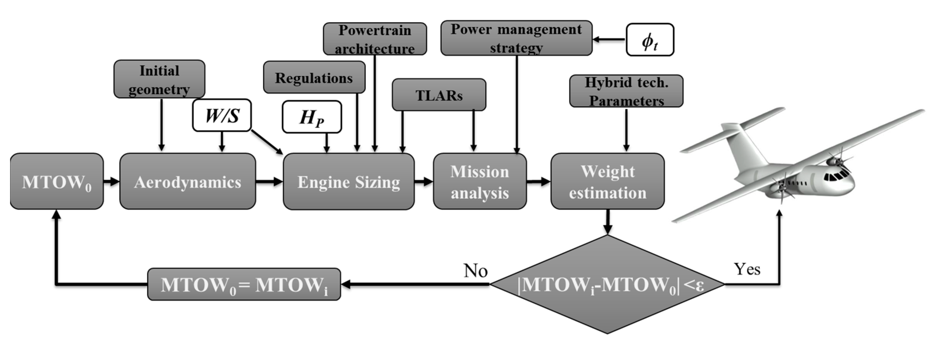
2.1. Conceptual Design Tool
2.2. Optimization Framework
3. Top-Level Aircraft Requirements and Main Aircraft Data
4. Results
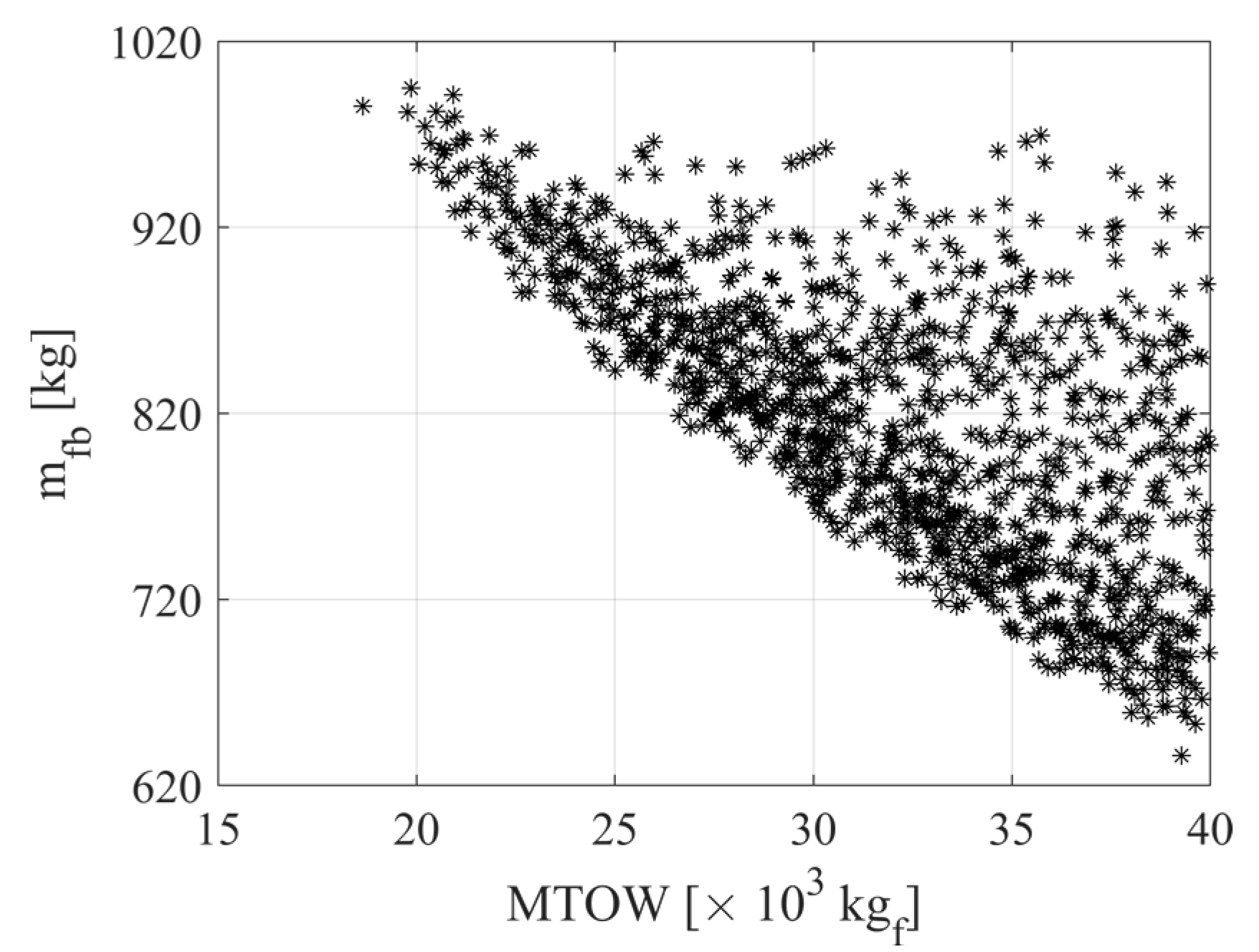
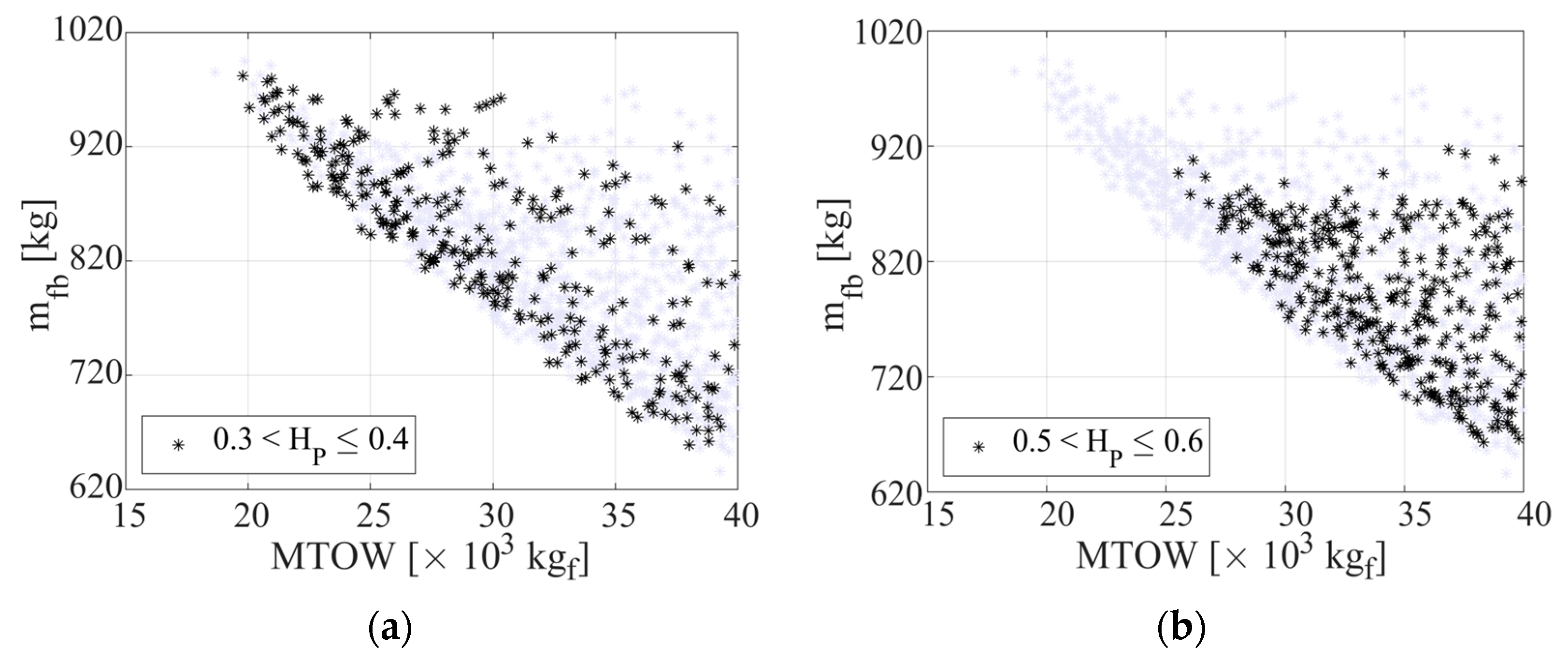
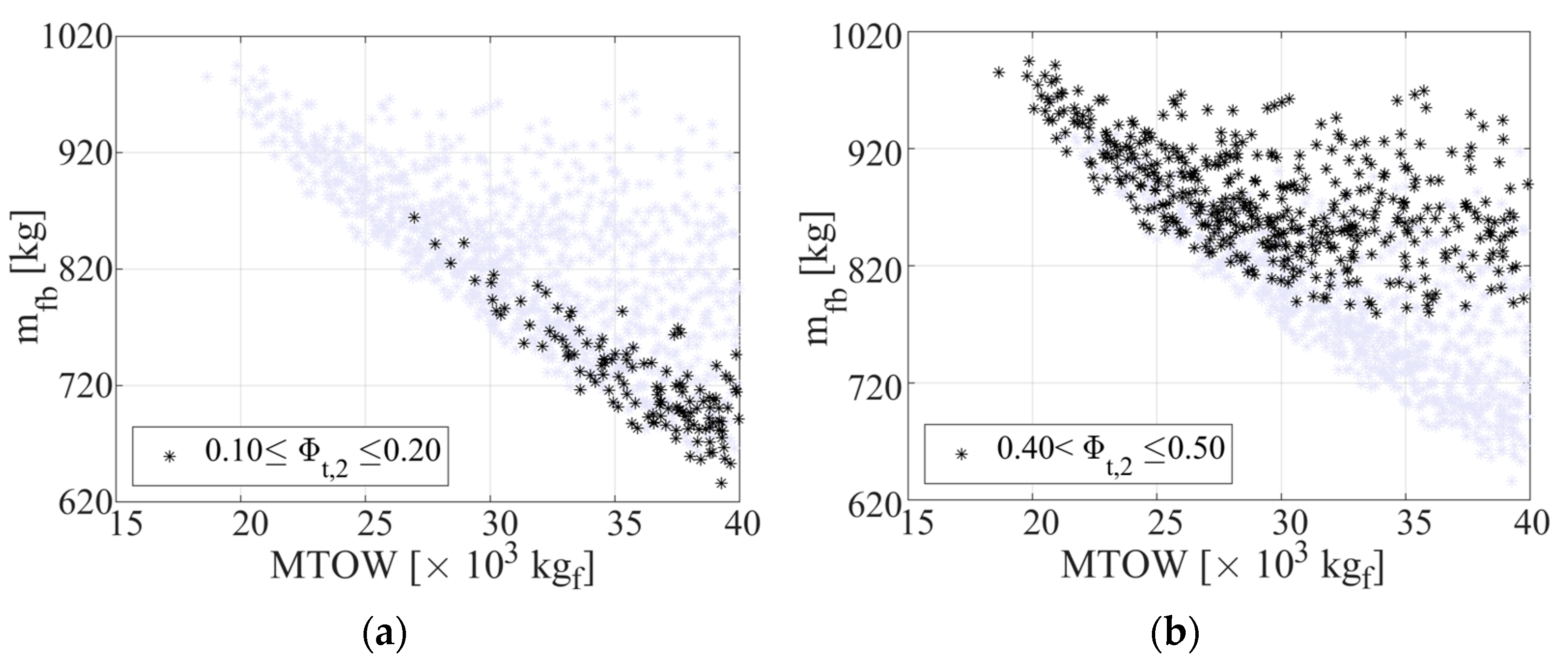
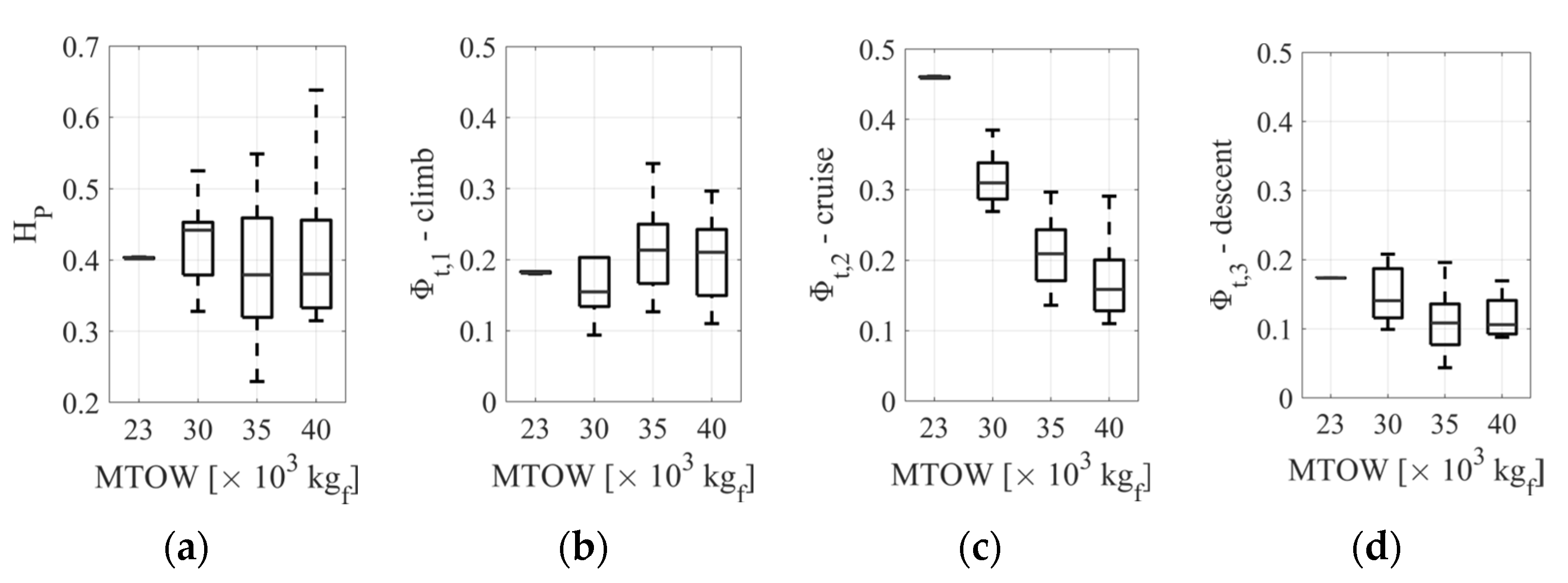
4.1. Parametric Analysis of the Design Variables
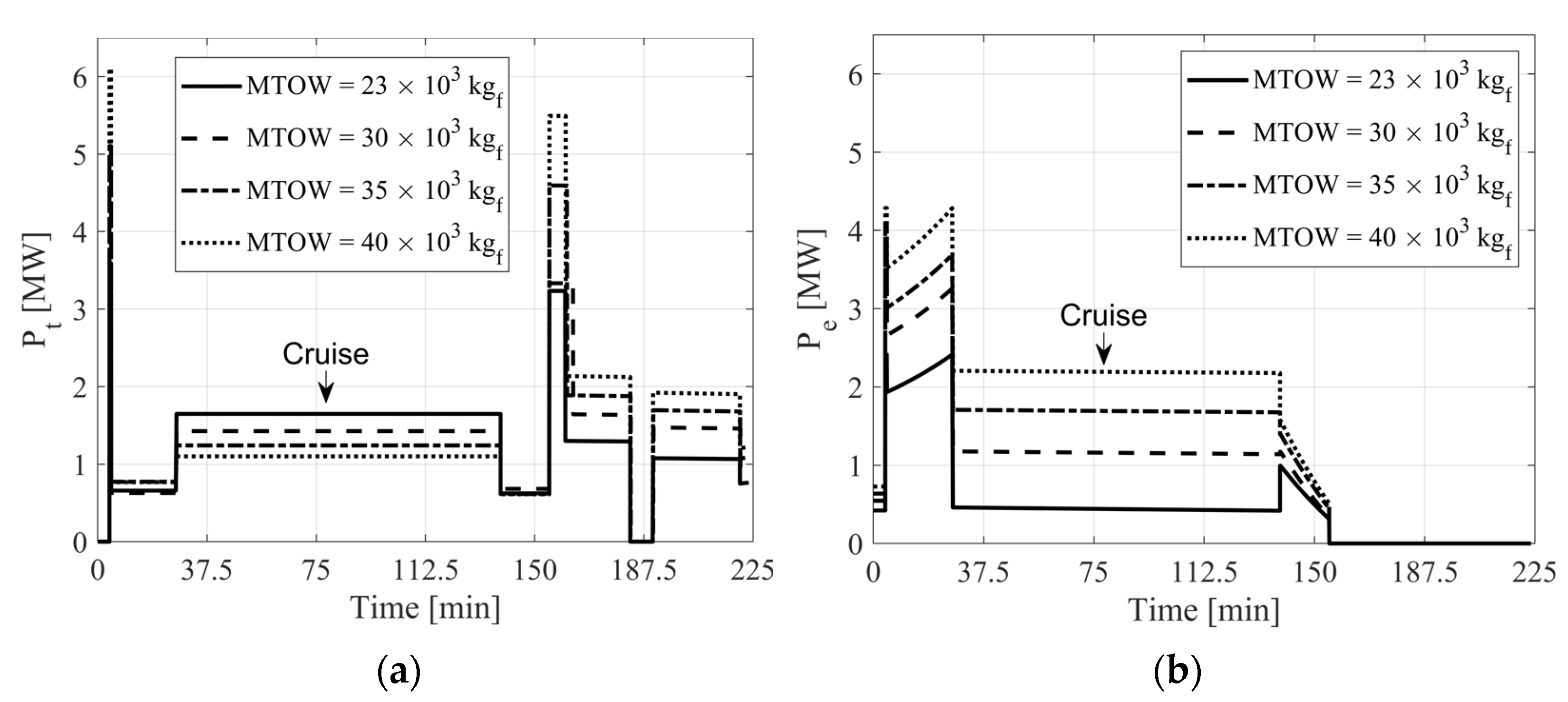
4.2. Optimization Results: Three-Stage Mission
4.3. Optimization Results: Parametric Analysis of the Number of Stages Dividing the Mission
5. Discussion
6. Conclusions
Author Contributions
Funding
Data Availability Statement
Conflicts of Interest
Abbreviations
| List of Acronyms | |
| BSFC | Brake-Specific Fuel Consumption |
| FAR | Federal Aviation Regulations |
| FoM | Figure of Merit |
| IAS | Indicated Air Speed |
| ICAO | Internal Civil Aviation Organization |
| MTOW | Maximum Take-Off Weight |
| OEW | Operating Empty Weight |
| TLARs | Top-Level Aircraft Requirements |
| List of Symbols | |
| BED | battery energy density [Wh/kg] |
| D | drag [N] |
| energy stored in the battery [J] | |
| degree of hybridization | |
| brake-specific fuel consumption [kg/kWh] | |
| L | lift [N] |
| M | Mach number |
| battery mass [kg] | |
| block fuel [kg] | |
| n | number of optimization runs |
| P | power requested to fly [W] |
| power supplied by the battery pack [W] | |
| power supplied by the fuel [W] | |
| power supplied by the electric motor [W] | |
| power supplied by the thermal engine [W] | |
| final battery state of charge | |
| initial battery state of charge | |
| t | time [s] |
| V | aircraft speed [m/s] |
| W | ] |
| /s] | |
| W/S | ] |
| ∆t | time step [s] |
| trajectory slope | |
| powertrain efficiency | |
| battery efficiency | |
| electric motor efficiency | |
| inverter efficiency | |
| thermal chain efficiency | |
| max electric motor power fraction supplied | |
| electric motor power fraction supplied | |
| max thermal engine power fraction supplied | |
| thermal engine power fraction supplied | |
| constraint parameter for thermal engine | |
| air density at sea level [kg/m3] | |
| air density [kg/m3] | |
| superscript a | available |
| superscript i | installed |
| subscript k | k-th stage |
References
- Platzer, M.F. A perspective on the urgency for green aviation. Prog. Aerosp. Sci. 2023, 141, 100932. [Google Scholar] [CrossRef]
- Ficca, A.; Marulo, F.; Sollo, A. An open thinking for a vision on sustainable green aviation. Prog. Aerosp. Sci. 2023, 141, 100928. [Google Scholar] [CrossRef]
- Ryley, T.; Baumeister, S.; Coulter, L. Climate change influences on aviation: A literature review. Transp. Policy 2020, 92, 55–64. [Google Scholar] [CrossRef]
- Delbecq, S.; Fontane, J.; Gourdain, N.; Planès, T.; Simatos, F. Sustainable aviation in the context of the Paris Agreement: A review of prospective scenarios and their technological mitigation levers. Prog. Aerosp. Sci. 2023, 141, 100920. [Google Scholar] [CrossRef]
- Jensen, L.L.; Bonnefoy, P.A.; Hileman, J.I.; Fitzgerald, J.T. The carbon dioxide challenge facing US aviation and paths to achieve net zero emissions by 2050. Prog. Aerosp. Sci. 2023, 141, 100921. [Google Scholar] [CrossRef]
- Bows-Larkin, A.; Mander, S.L.; Traut, M.B.; Anderson, K.L.; Wood, F.R. Aviation and Climate Change—The Continuing Challenge. In Encyclopedia of Aerospace Engineering; John Wiley & Sons: Hoboken, NJ, USA, 2016. [Google Scholar] [CrossRef]
- Graver, B.; Rutherford, D. CO2 Emissions from Commercial Aviation: 2013, 2018 and 2019; ICCT, The International Council on Clean Transportation: Washington, DC, USA, 2019. [Google Scholar]
- Franz, S.; Rottoli, M.; Bertram, C. The wide range of possible aviation demand futures after the COVID-19 pandemic. Environ. Res. Lett. 2022, 17, 064009. [Google Scholar] [CrossRef]
- Afonso, F.; Sohst, M.; Diogo, C.M.; Rodrigues, S.S.; Ferreira, A.; Ribeiro, I. Strategies towards a more sustainable aviation: A systematic review. Prog. Aerosp. Sci. 2023, 137, 100878. [Google Scholar] [CrossRef]
- Brelje, B.; Martins, J.R. Electric, hybrid, and turboelectric fixed-wing aircraft: A review of concepts, models, and design approaches. Prog. Aerosp. Sci. 2018, 104, 1–19. [Google Scholar] [CrossRef]
- Abu Salem, K.; Palaia, G.; Quarta, A. Review of hybrid-electric aircraft technologies and designs: Critical analysis and novel solutions. Prog. Aerosp. Sci. 2023, 141, 100924. [Google Scholar] [CrossRef]
- Kuśmierek, A.; Galiński, C.; Stalewski, W. Review of the hybrid gas-electric aircraft propulsion systems versus alternative systems. Prog. Aerosp. Sci. 2023, 141, 100925. [Google Scholar] [CrossRef]
- Sahoo, S.; Zhao, X.; Kyprianidis, K. A Review of Concepts, Benefits, and Challenges for Future Electrical Propulsion-Based Aircraft. Aerospace 2020, 7, 44. [Google Scholar] [CrossRef]
- Jones, C.E.; Norman, P.J.; Burt, G.M.; Hill, C.; Allegri, G.; Yon, J.M. A Route to Sustainable Aviation: A Roadmap for the Realization of Aircraft Components With Electrical and Structural Multifunctionality. IEEE Trans. Transp. Electrif. 2021, 7, 3032–3049. [Google Scholar] [CrossRef]
- Adler, E.J.; Martins, J. Hydrogen-powered aircraft: Fundamental concepts, key technologies, and environmental impacts. Prog. Aerosp. Sci. 2023, 141, 100922. [Google Scholar] [CrossRef]
- Cipolla, V.; Zanetti, D.; Abu Salem, K.; Binante, V.; Palaia, G. A Parametric Approach for Conceptual Integration and Performance Studies of Liquid Hydrogen Short–Medium Range Aircraft. Appl. Sci. 2022, 12, 6857. [Google Scholar] [CrossRef]
- Degirmenci, H.; Uludag, A.; Ekici, S.; Karakoc, T.H. Challenges, prospects and potential future orientation of hydrogen aviation and the airport hydrogen supply network: A state-of-art review. Prog. Aerosp. Sci. 2023, 141, 100923. [Google Scholar] [CrossRef]
- Magrini, A.; Benini, E.; Yao, H.D.; Postma, J.; Sheaf, C. A review of installation effects of ultra-high bypass ratio engines. Prog. Aerosp. Sci. 2020, 119, 100680. [Google Scholar] [CrossRef]
- Abu Salem KPalaia, G.; Bravo-Mosquera, P.D.; Quarta, A.A. A Review of Novel and Non-Conventional Propulsion Integrations for Next-Generation Aircraft. Designs 2024, 8, 20. [Google Scholar] [CrossRef]
- Moirou, N.G.; Sanders, D.S.; Laskaridis, P. Advancements and prospects of boundary layer ingestion propulsion concepts. Prog. Aerosp. Sci. 2023, 138, 100897. [Google Scholar] [CrossRef]
- Fard, M.T.; He, J.; Huang, H.; Cao, Y. Aircraft Distributed Electric Propulsion Technologies—A Review. IEEE Trans. Transp. Electrif. 2022, 8, 4067–4090. [Google Scholar] [CrossRef]
- Bravo-Mosquera, P.D.; Cerón-Muñoz, H.D.; Catalano, F.M. Design, aerodynamic analysis and optimization of a next-generation commercial airliner. J. Braz. Soc. Mech. Sci. Eng. 2022, 44, 609. [Google Scholar] [CrossRef]
- Abu Salem, K.; Cipolla, V.; Palaia, G.; Binante, V.; Zanetti, D. A Physics-Based Multidisciplinary Approach for the Preliminary Design and Performance Analysis of a Medium Range Aircraft with Box-Wing Architecture. Aerospace 2021, 8, 292. [Google Scholar] [CrossRef]
- Li, L.; Bai, J.; Qu, F. Multipoint Aerodynamic Shape Optimization of a Truss-Braced-Wing Aircraft. J. Aircr. 2022, 59, 1179–1194. [Google Scholar] [CrossRef]
- Grazioso, G.; De Marco, A. Strut-braced wing induced drag modeling for regional turboprop aircraft design. In Proceedings of the 34th ICAS Congress, Florence, Italy, 9–13 September 2024; Available online: https://www.icas.org/ICAS_ARCHIVE/ICAS2024/data/papers/ICAS2024_0462_paper.pdf (accessed on 8 December 2024).
- Cavallaro, R.; Simon, P.N.; Cini, A. Local air quality and noise optimization of a large aspect ratio wings with distributed hybrid electric propulsion. In Proceedings of the 34th ICAS Congress, Florence, Italy, 9–13 September 2024. Available online: https://www.icas.org/ICAS_ARCHIVE/ICAS2024/data/papers/ICAS2024_1067_paper.pdf (accessed on 8 December 2024).
- Okonkwo, P.; Smith, H. Review of evolving trends in blended wing body aircraft design. Prog. Aerosp. Sci. 2016, 82, 1–23. [Google Scholar] [CrossRef]
- Palaia, G.; Abu Salem, K.; Quarta, A. Parametric Analysis for Hybrid–Electric Regional Aircraft Conceptual Design and Development. Appl. Sci. 2023, 13, 11113. [Google Scholar] [CrossRef]
- Finger, D.F.; Braun, C.; Bil, C. Impact of battery performance on the initial sizing of hybrid-electric general aviation aircraft. J. Aerosp. Eng. 2020, 33, 1–18. [Google Scholar] [CrossRef]
- Viswanathan, V.; Epstein, A.H.; Chiang, Y.M.; Takeuchi, E.; Bradley, M.; Langford, J.; Winter, M. The challenges and opportunities of battery-powered flight. Nature 2022, 601, 519–525. [Google Scholar] [CrossRef] [PubMed]
- Palaia, G.; Abu Salem, K.; Quarta, A. Comparative analysis of hybrid-electric regional aircraft with tube-and-wing and box-wing airframes: A performance study. Appl. Sci. 2023, 13, 7894. [Google Scholar] [CrossRef]
- De Vries, R.; Brown, M.; Vos, R. Preliminary sizing method for hybrid-electric distributed-propulsion aircraft. J. Aircr. 2019, 56. [Google Scholar] [CrossRef]
- Figueroa, R.Q.; Cavallaro, R.; Cini, A. Feasibility Studies on Regional Aircraft Retrofitted with Hybrid-Electric Powertrains. Aerosp. Sci. Technol. 2024, 151, 109246. [Google Scholar] [CrossRef]
- Reid, S.J.; Perez, R.E.; Jansen, P.W. Hybrid electric aircraft design with optimal power management. Aerosp. Sci. Technol. 2024, 109479, 154. [Google Scholar] [CrossRef]
- Voskuijl, M.; Van Bogaert, J.; Rao, A.G. Analysis and design of hybrid-electric regional turboprop aircraft. CEAS Aeronaut. J. 2017, 9, 15–25. [Google Scholar] [CrossRef]
- Marciello, V.; Di Stasio, M.; Ruocco, M.; Trifari, V.; Nicolosi, F.; Meindl, M. Design Exploration for Sustainable Regional Hybrid-Electric Aircraft: A Study Based on Technology Forecasts. Aerospace 2023, 10, 165. [Google Scholar] [CrossRef]
- Moebs, N.; Eisenhut, D.; Windels, E.; Van der Pols, J.; Strohmayer, A. Adaptive Initial Sizing Method and Safety Assessment for Hybrid-Electric Regional Aircraft. Aerospace 2022, 9, 150. [Google Scholar] [CrossRef]
- Habermann, A.L.; Kolb, M.G.; Maas, P.; Kellermann, H.; Rischmüller, C.; Peter, F.; Seitz, A. Study of a Regional Turboprop Aircraft with Electrically Assisted Turboshaft. Aerospace 2023, 10, 529. [Google Scholar] [CrossRef]
- Gesell, H.; Wolters, F.; Plohr, M. System analysis of turbo-electric and hybrid electric propulsion systems on a regional aircraft. Aeronaut. J. 2019, 123, 1602–1617. [Google Scholar] [CrossRef]
- Finger, D.F.; Braun, C.; Bil, C. Comparative assessment of parallel-hybrid-electric propulsion systems for four different aircraft. J. Aircr. 2020, 57, 843–853. [Google Scholar] [CrossRef]
- Hoelzen, J.; Liu, Y.; Bensmann, B.; Winnefeld, C.; Elham, A.; Friedrichs, J.; Hanke-Rauschenbach, R. Conceptual design of operation strategies for hybrid electric aircraft. Energies 2018, 11, 217. [Google Scholar] [CrossRef]
- Karpuk, S.; Elham, A. Influence of novel airframe technologies on the feasibility of fully-electric regional aviation. Aerospace 2021, 8, 163. [Google Scholar] [CrossRef]
- Abu Salem, K.; Palaia, G.; Quarta, A. Introducing the Box-Wing Airframe for Hybrid-Electric Regional Aircraft: A Preliminary Impact Assessment. Appl. Sci. 2023, 13, 10506. [Google Scholar] [CrossRef]
- Abu Salem, K.; Palaia, G.; Quarta, A.; Chiarelli, M. Medium-Range Aircraft Conceptual Design from a Local Air Quality and Climate Change Viewpoint. Energies 2023, 16, 4013. [Google Scholar] [CrossRef]
- Xie, Y.; Savvarisal, A.; Tsourdos, A.; Zhang, D.; Jason, G.U. Review of hybrid electric powered aircraft, its conceptual design and energy management methodologies. Chin. J. Aeronaut. 2021, 34, 432–450. [Google Scholar] [CrossRef]
- Doff-Sotta, M.; Cannon, M.; Bacic, M. Predictive Energy Management for Hybrid Electric Aircraft Propulsion Systems. IEEE Trans. Control Syst. Technol. 2023, 31, 602–614. [Google Scholar] [CrossRef]
- Montazeri-Gh, M.; Khasheinejad, M. Dynamic Modeling and Rule-Based Control Design for a Hybrid-Electrified Regional Aircraft. IEEE Trans. Transp. Electrif. 2022, 8, 4140–4147. [Google Scholar] [CrossRef]
- Wang, M.; Mesbahi, M. To Charge In-Flight or Not: A Comparison of Two Parallel Hybrid Electric Aircraft Configurations via Optimal Control. IEEE Trans. Transp. Electrif. 2024, 10, 475–484. [Google Scholar] [CrossRef]
- Leite, J.P.S.P.; Voskuijl, M. Optimal energy management for hybrid-electric aircraft. Aircr. Eng. Aerosp. Technol. 2020, 92, 851–861. [Google Scholar] [CrossRef]
- Zhang, J.; Roumeliotis, I.; Zolotas, A. Nonlinear Model Predictive Control-Based Optimal Energy Management for Hybrid Electric Aircraft Considering Aerodynamics-Propulsion Coupling Effects. IEEE Trans. Transp. Electrif. 2022, 8, 2640–2653. [Google Scholar] [CrossRef]
- Riboldi, C.E.D. Energy-optimal off-design power management for hybrid-electric aircraft. Aerosp. Sci. Technol. 2019, 95, 105507. [Google Scholar] [CrossRef]
- Spinelli, A.; Enalou, H.B.; Zaghari, B.; Kipouros, T.; Laskaridis, P. Application of Probabilistic Set-Based Design Exploration on the Energy Management of a Hybrid-Electric Aircraft. Aerospace 2022, 9, 147. [Google Scholar] [CrossRef]
- Palaia, G.; Abu Salem, K. Mission Performance Analysis of Hybrid-Electric Regional Aircraft. Aerospace 2023, 10, 105507. [Google Scholar] [CrossRef]
- Palaia, G.; Zanetti, D.; Abu Salem, K.; Cipolla, V.; Binante, V. THEA-CODE: A design tool for the conceptual design of hybrid-electric aircraft with conventional or unconventional airframe configurations. Mech. Ind. 2021, 22, 19. [Google Scholar] [CrossRef]
- Pornet, C.; Isikveren, A.T. Conceptual design of hybrid-electric transport aircraft. Prog. Aerosp. Sci. 2015, 79, 114–135. [Google Scholar] [CrossRef]
- Vratny, P.C.; Gologan, C.; Pornet, C.; Isikveren, A.T.; Hornung, M. Battery Pack Modeling Methods for Universally-Electric Aircraft. In Proceedings of the 4th CEAS Air & Space Conference, Linköping, Sweden, 16–19 September 2013. [Google Scholar]
- Abu Salem, K.; Palaia, G.; Quarta, A. Impact of Figures of Merit Selection on the Hybrid-Electric Regional Aircraft Performance Analysis. Energies 2023, 16, 7881. [Google Scholar] [CrossRef]
- Fletcher, R. Practical Methods of Optimization; John Wiley & Sons: Hoboken, NJ, USA, 2013; ISBN 978-1-118-72318-0. [Google Scholar]
- Martins, J.R.; Ning, A. Engineering Design Optimization; Cambridge University Press: Cambridge, UK, 2021; ISBN 978-1108833417. [Google Scholar]
- Dever, T.P.; Duffy, K.P.; Provenza, A.J.; Loyselle, P.L.; Choi, B.B.; Morrison, C.R.; Lowe, A.M. Assessment of Technologies for Noncryogenic Hybrid Electric Propulsion; Technical Report NASA/TP—2015-216588; NASA: Cleveland, OH, USA, 2015. [Google Scholar]
- Donateo, T.; Ficarella, A. A Methodology for the Comparative Analysis of Hybrid Electric and All-Electric Power Systems for Urban Air Mobility. Energies 2022, 15, 638. [Google Scholar] [CrossRef]
- Marciello, V.; Cusati, V.; Nicolosi, F.; Saavedra-Rubio, K.; Pierrat, E.; Thonemann, N.; Laurent, A. Evaluating the economic landscape of hybrid-electric regional aircraft: A cost analysis across three time horizons. Energy Convers. Manag. 2024, 312, 118517. [Google Scholar] [CrossRef]
- Palaia, G.; Abu Salem, K. Environmental implications of hybrid-electric regional aircraft: Emissions and climate change. In Proceedings of the 34th ICAS Conference, Florence, Italy, 9–13 September 2024; Available online: https://www.icas.org/icas_archive/icas2024/data/papers/icas2024_0222_paper.pdf (accessed on 8 December 2024).
- Palaia, G.; Abu Salem, K. Power management supply optimization for hybrid-electric regional aircraft. In Proceedings of the 34th ICAS Conference, Florence, Italy, 9–13 September 2024; Available online: https://www.icas.org/ICAS_ARCHIVE/ICAS2024/data/papers/ICAS2024_0303_paper.pdf (accessed on 8 December 2024).


| Aerodynamics | Input | Aircraft weight Geometric parameters of the lifting system, i.e., aspect ratio, taper ratio, sweep angle, W/S TLARs, i.e., cruise altitude and related Mach number |
| Output | Aircraft polar drag | |
| Engine Sizing | Input | Aircraft polar drag and weight Current regulations, i.e., FAR W/S and TLARs, i.e., cruise altitude and related Mach number |
| Output | Electric and thermal installed power | |
| Mission Analysis | Input | Aircraft polar drag and weight Mission profile Power management parameters, i.e., Powertrain model |
| Output | Fuel consumption and battery weight, mission parameters | |
| Weight Estimation | Input | Aircraft weight and geometry TLARs |
| Output | Aircraft weight breakdown |
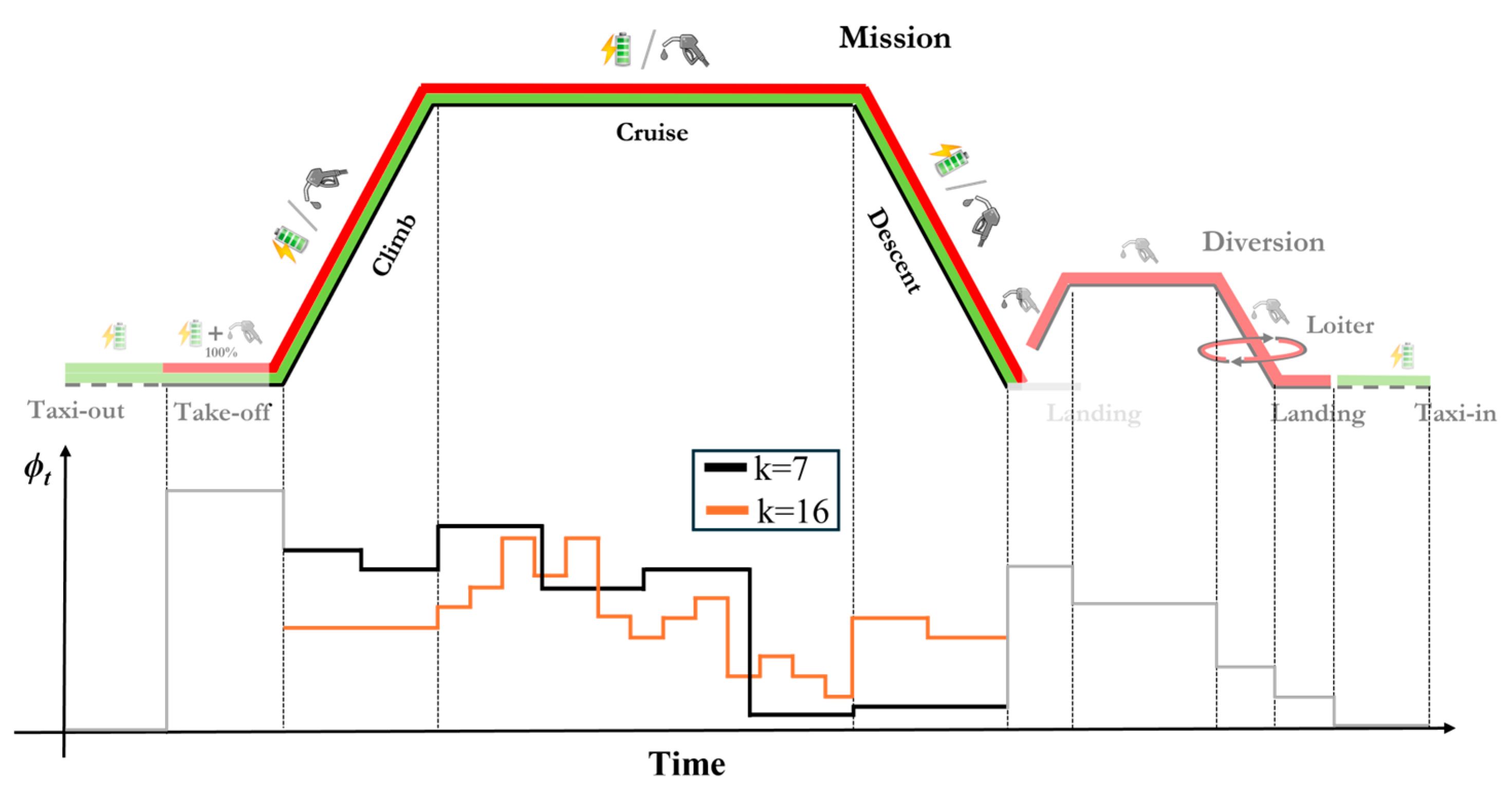
| Mission Phase | Assumption |
|---|---|
| Climb | IAS = 170 kt, rate of climb = 900 ft/min |
| Cruise | M = 0.4 @ flight level = 200 |
| Descent | IAS = 220 kt, rate of descent = −1100 ft/min |
| Range [nm] | 400 | 600 | 800 |
| Wingspan [m] | 20.5 | 20.9 | 21.9 |
| Wing surface [m2] | 46.6 | 48.2 | 50.3 |
| Tail surface [m2] | 13 | 13.5 | 14 |
| MTOW [kgf] | 15,153 | 15,731 | 16,365 |
| OEW [kgf] | 10,361 | 10,550 | 10,766 |
| Total fuel [kg] | 1042 | 1432 | 1837 |
| Block fuel [kg] | 733 | 1103 | 1487 |
| Installed power [MW] | 4 | 4.15 | 4.3 |
| Variable | Value | |||
|---|---|---|---|---|
| [] | 23,000 | 30,000 | 35,013 | 40,049 |
| 0.402 | 0.525 | 0.438 | 0.413 | |
| 0.183 | 0.169 | 0.151 | 0.128 | |
| 0.459 | 0.385 | 0.243 | 0.180 | |
| 0.173 | 0.184 | 0.120 | 0.100 | |
| [MW] | 3.593 | 3.704 | 5.105 | 6.102 |
| [MW] | 2.489 | 4.221 | 4.108 | 4.418 |
| [kg] | 4291 | 8196 | 10,962 | 13,698 |
| [kg] | 872 | 764 | 688 | 620 |
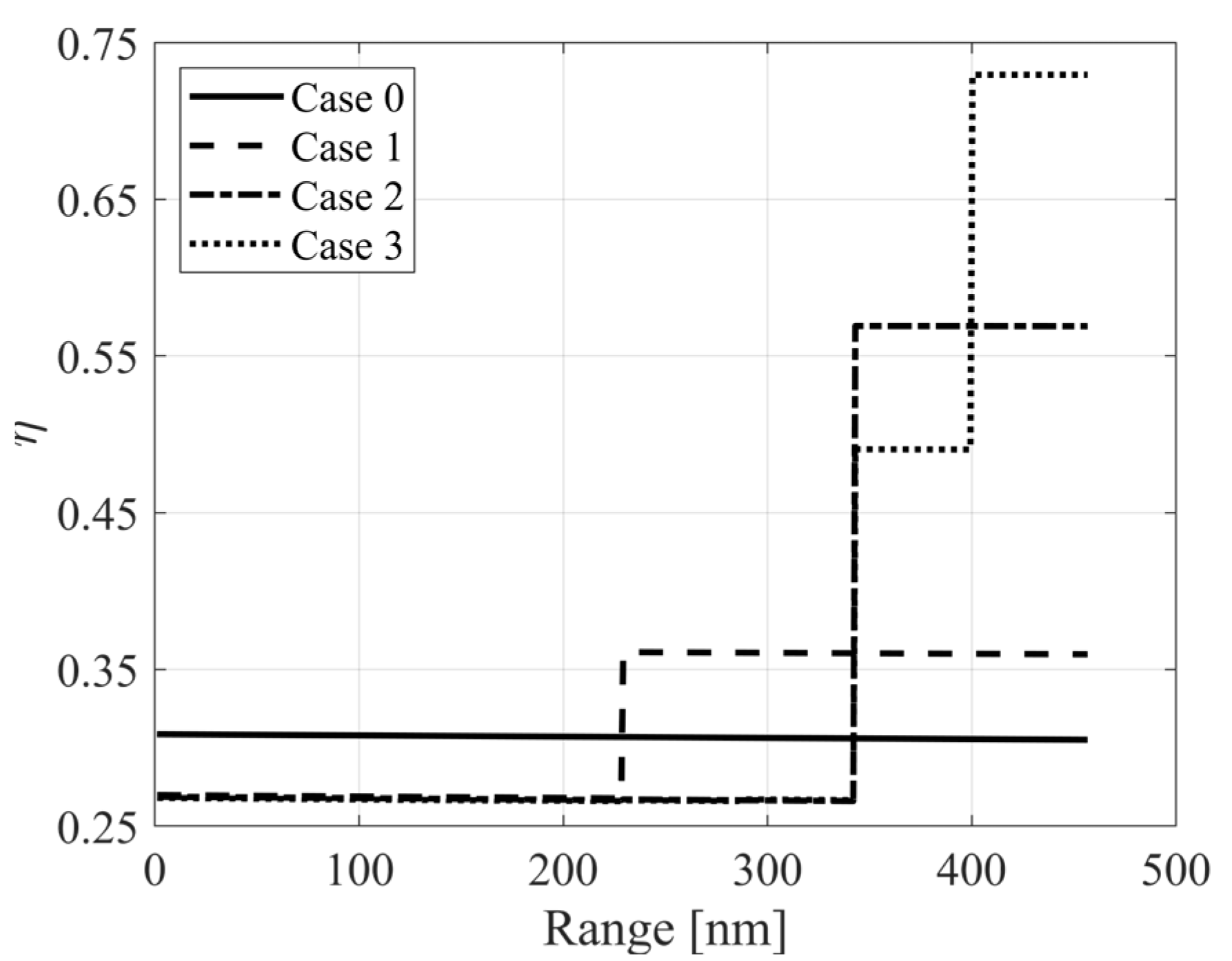
| Analyzed Case | Description |
|---|---|
| Case 0 | One stage at cruise phase |
| Case 1 | Two stages at cruise phase |
| Case 2 | Four stages at cruise phase |
| Case 3 | Eight stages at cruise phase |
Disclaimer/Publisher’s Note: The statements, opinions and data contained in all publications are solely those of the individual author(s) and contributor(s) and not of MDPI and/or the editor(s). MDPI and/or the editor(s) disclaim responsibility for any injury to people or property resulting from any ideas, methods, instructions or products referred to in the content. |
© 2025 by the authors. Licensee MDPI, Basel, Switzerland. This article is an open access article distributed under the terms and conditions of the Creative Commons Attribution (CC BY) license (https://creativecommons.org/licenses/by/4.0/).
Share and Cite
Palaia, G.; Abu Salem, K.; Carrera, E. Efficient Methodology for Power Management Optimization of Hybrid-Electric Aircraft. Aerospace 2025, 12, 230. https://doi.org/10.3390/aerospace12030230
Palaia G, Abu Salem K, Carrera E. Efficient Methodology for Power Management Optimization of Hybrid-Electric Aircraft. Aerospace. 2025; 12(3):230. https://doi.org/10.3390/aerospace12030230
Chicago/Turabian StylePalaia, Giuseppe, Karim Abu Salem, and Erasmo Carrera. 2025. "Efficient Methodology for Power Management Optimization of Hybrid-Electric Aircraft" Aerospace 12, no. 3: 230. https://doi.org/10.3390/aerospace12030230
APA StylePalaia, G., Abu Salem, K., & Carrera, E. (2025). Efficient Methodology for Power Management Optimization of Hybrid-Electric Aircraft. Aerospace, 12(3), 230. https://doi.org/10.3390/aerospace12030230