Article

Analysis of Flutter Characteristics for Composite Laminates in Hypersonic Yawed Flow

1
Key Laboratory of Unsteady Aerodynamics and Flow Control, Ministry of Industry and Information Technology, Nanjing University of Aeronautics and Astronautics, Nanjing 210016, China
2
AVIC Shenyang Aircraft Design and Research Institute, Shenyang 110035, China
*
Author to whom correspondence should be addressed.
Aerospace 2025, 12(3), 174; https://doi.org/10.3390/aerospace12030174
Submission received: 23 January 2025 / Revised: 16 February 2025 / Accepted: 19 February 2025 / Published: 21 February 2025
(This article belongs to the Special Issue Advanced Aircraft Structural Design and Applications)

Abstract

:
This paper investigates the flutter characteristics of composite laminates in hypersonic yawed flow using numerical simulations. The governing equations are derived based on Hamilton’s principle and were discretized using the assumed mode method. The unsteady aerodynamic force is calculated by using the piston theory, including the influence of the yaw angle. Several laminate models are designed to study the effects of the stacking sequence, thickness ratio, and fiber orientation on the critical dynamic pressure and the amplitude of the limit cycle oscillation. Numerical results show that positioning the material with higher stiffness on the upper layer can lead to a higher critical dynamic pressure and a smaller amplitude of the limit cycle oscillation. In the case of large yaw angles, increasing the thickness of the material with larger stiffness can clearly suppress the amplitude of the limit cycle oscillation. Fiber orientation symmetry to the x-axis can improve the flight stability with the change in the yaw angle.

1. Introduction

Thin-walled structures such as panels and laminates are largely used in aircraft skins and rudders. Compared to subsonic or supersonic flow, the fluid–structure interactions in these structures are more serious in hypersonic flow, probably leading to the panel flutter phenomenon. If panel flutter occurs, it may cause fatigue or damage to the structures [1,2]. To prevent or delay flutter onset, the mechanical properties of the materials must be optimized. Along the flow direction, the stiffness of composite materials is generally larger than that of isotropic materials, but the stiffness in other directions is smaller, resulting in aeroelastic instability in hypersonic yawed flow. If flutter occurs, we need to minimize the amplitude of limit cycle oscillation (LCO amplitude) to avoid structural damage. This paper focuses on the flutter characteristics of composite laminates in hypersonic yawed flow, including the critical dynamic pressure and the LCO amplitude.
Over the past few decades, the frequency domain method is usually used to predict the critical dynamic pressure [3,4,5,6,7], but it is difficult to analyze the behavior when flutter occurs. Dowell [8,9,10] developed kinetic equations utilizing the large deformation theory proposed by Von-Karman in the time domain, and the critical dynamic pressure and LCO amplitude of the panel were calculated. On this basis, the impact of symmetrical layering, static pressure differential, and aerodynamic damping on the flutter characteristics of composite laminates in supersonic flow have been investigated [11,12]. In the last twenty years, the effects of thermal loading and acoustic excitation at varying flow velocities have been studied [13]. Xie et al. [14] used the potential of utilizing low-order Galerkin modes to enhance computational efficiency for three-dimensional panels with varying structures. In recent years, the governing equations of the curved panel have been established, and the results show that the flutter characteristics of the curved panel were much different from those of the flat panel [15,16,17,18]. Lin et al. [19] analyzed the flutter characteristics of composite laminates under various boundary conditions. Zhou et al. [20] analyzed the vibration and flutter behavior of supersonic porous composite laminates under elastic support, especially the boundary conditions, volume fraction index, temperature distribution, and pore volume fraction. Chai et al. [21] summarized the nonlinear dynamic characteristics of lattice composite laminates on a Winkler elastic foundation. Meng et al. [22] derived the maximum point of the LCO amplitude of the two-dimensional panel and used the CFD-CSD method for numerical verification. Abdukhakimov et al. [23] analyzed the flutter characteristics of the panel in low-speed flow using the potential flow theory. Moreira et al. [24] studied the fluid–structure interactions and vibration control of a panel with piezoelectric patches. The modal reduction technique is widely used in the study of flutter problems. Mozaffari-Jovin, S. et al. [25] studied the aeroelastic interaction of a locally distributed, flap-type control surface with aircraft wings operating in a subsonic potential flow field. An analytical solution to this boundary value problem is then accomplished by assumed modes and the extended Galerkin’s method. Vindigni, C.R. et al. [26] used a hybrid semi-analytical reduced-order aerodynamic model to analyze the aeroelasticity of structures in subsonic flow.
There have been many studies on single-layer panels and laminates. However, most of them do not consider the case with a non-zero yaw angle. In fact, when the hypersonic vehicle is maneuvering, the direction of the incoming flow will no longer be along the axial direction and the yaw angle will not be zero. In this case, the elastic modulus of the anisotropic material along the flow direction will be different from that at a yaw angle of zero. As the yaw angle increases, the influence of the axial elastic modulus decreases, and the influence of the normal elastic modulus increases. Therefore, the mechanical properties will be changed [11,27,28], which may lead to aeroelastic instability. In order to obtain the flutter characteristics of the composite laminates in hypersonic yawed flow, we need to analyze the influence of typical parameters. After obtaining the influence of some key parameters on the flutter characteristics, some methods will be proposed which can delay the flutter or suppress the LCO amplitude.
In this work, the influences of the stacking sequence, thickness ratio, and fiber orientation on the flutter characteristics of composite laminates will be studied. The remainder of this paper is organized as follows: Section 2 introduces the governing equations and the numerical method. Section 3 introduces the used laminated models and then comprehensively analyzes the effects of the stacking sequence, thickness of each layer, and fiber orientation on the flutter characteristics of composite laminates in hypersonic yawed flow. Particularly, theoretical analysis of the effect of the material placed on the upper layer on the critical dynamic pressure is also provided. Section 4 gives the conclusions.

2. Methodology

2.1. Constitutive Relation

Thin-walled structures composed of composite laminates consist of multiple material layers. According to the nonlinear strain theory developed by Von-Karman [13], the geometric nonlinear strain in each layer is as follows:
ε x = u x z 2 w x 2 + 1 2 ( w x ) 2 ε y = v y z 2 w y 2 + 1 2 ( w y ) 2 γ x y = u y + v x + w x w y 2 z 2 w x y
where ε x and ε y are the normal strain, γ x y is the shear strain, u , v and w are the displacements of the mid-plane in the x , y and z directions, respectively.
The relationship between stress and strain of the kth layer is expressed as [11]
σ x k σ y k τ x y k = Q 11 Q 12 0 Q 12 Q 22 0 0 0 Q 66 ε x ε y γ x y
where σ x k and σ y k are normal stress, τ x y k is shear stress, and Q i j is the elastic stiffness coefficient determined by the mechanical properties of the material. For a fiber orientation angle of θ k , the transformation relation of Q i j can be written as
Q 11 k ¯ Q 12 k ¯ Q 16 k ¯ Q 21 k ¯ Q 22 k ¯ Q 26 k ¯ Q 16 k ¯ Q 26 k ¯ Q 66 k ¯ = T k Q 11 Q 12 0 Q 12 Q 22 0 0 0 Q 66 T k T
where T k is the transformation matrix, which can be written as
T k = cos 2 θ k sin 2 θ k 2 sin θ k cos θ k sin 2 θ k cos 2 θ k 2 sin θ k cos θ k sin θ k cos θ k sin θ k cos θ k cos 2 θ k sin 2 θ k

2.2. Governing Equation

According to the Hamilton principle [11],
δ t 1 t 2 T U + W d t = 0
T is the kinetic energy, U is the strain energy, and W is the work performed by aerodynamic force, and the expressions are as follows:
T k = 1 2 0 a 0 b I 0 ( u t ) 2 + ( v t ) 2 + ( w t ) 2 2 I 1 ( u t ) ( 2 w x t ) 2 I 1 ( v t ) ( 2 w y t ) + I 2 ( 2 w x t ) 2 + I 2 ( 2 w y t ) 2 d x d y
U = 1 2 0 a 0 b 0 h σ x ε x + σ y ε y + τ x y γ x y   d x d y d z  
W = 0 a 0 b Δ p w d x d y
Substitute Equations (6)–(8) into Equation (5) and write them into a matrix form:
M X + K X = F
where M is the mass matrix, K is the stiffness matrix, and the aerodynamic force F is described by the piston theory including the influence of the yaw angle. Piston theory [8,9,10] has become a common method for calculating hypersonic aerodynamic force because of its simple expression. Although it cannot capture shock waves, it has high computational efficiency and its accuracy meets the needs of engineering field, and the specific expression is shown in Equation (10):
Δ p = ρ U 2 M 2 1 [ w x cos ( α ) + w y sin ( α ) + 1 U M 2 2 M 2 1 w t ]
where ρ is the flow density, U is the flow velocity, α is the yaw angle, and M is the Mach number. The three-dimensional matrix form of M , K , and F are shown in Equation (11), and the specific expression of them are shown in Appendix A.
M = M u u 0 M u w 0 M v v M v w M u w T M v w T M w w K = K uu K uv K uw K vu K vv K vw K wu K wv K ww F = 0 0 0 0 0 0 0 0 Δ p
Since the displacement cannot be obtained directly, the assumed mode method is used for numerical solution. For simply supported boundary conditions, the displacement can be written as
w ( x , y , t ) = m = 1 k 1 n = 1 k 2 φ m n q m n = m = 1 k 1 n = 1 k 2 s i n ( m π x a ) s i n ( n π y b ) q m n t
where w is the displacement and m and n are the modal orders in the x and y directions. q m n is a time-dependent parameter to be solved.
Increasing k 1 and k 2 in Equation (12) can improve the accuracy of the result, and a large number of studies show that it is appropriate to use the superposition of the first six modes for panel flutter calculation [15,20,29,30]. In this case, the dimension of matrix Equation (9) is 108. The Gauss–Legendre integral method is used for spatial discretization. Considering the balance between efficiency and accuracy, 10*10 integral points are selected in the x and y directions. The 4th order Runge–Kutta method is adopted to solve the differential equations. After the independent verification, the time-step-size is 5 × 10 6 s, and all the calculations in this paper use an in-house MATLAB 2022a code. In this study, the time domain method is used to determine the critical flutter point. By tracking the convergence or divergence of the displacement response curve, we judged whether the flow pressure had exceeded the critical value. Using an Intel Core i5-9500 CPU processor (3.00 GHz), it takes about half an hour to determine the divergence or convergence of the response curve, and it takes about 4 h to have a stable amplitude.

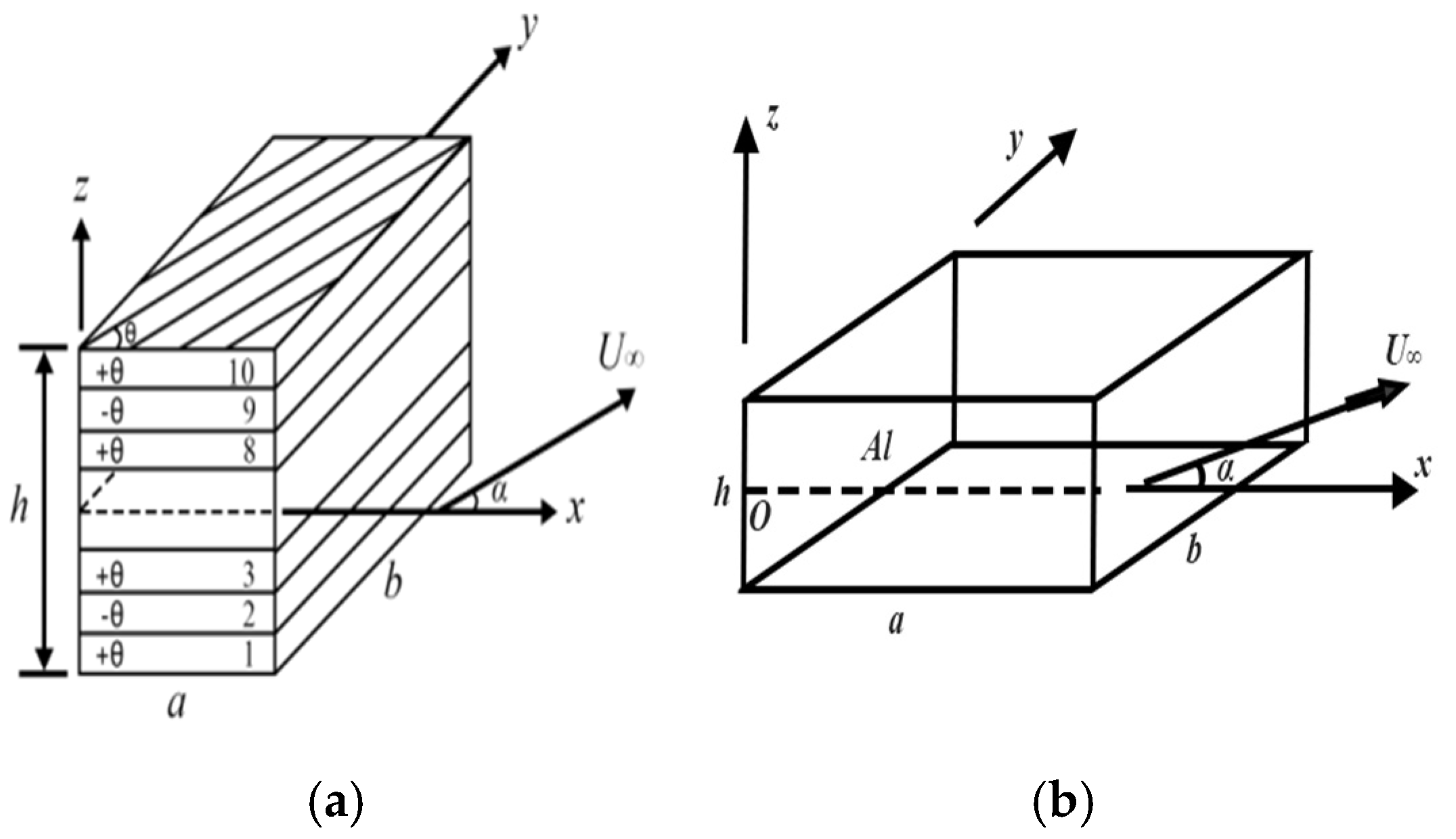
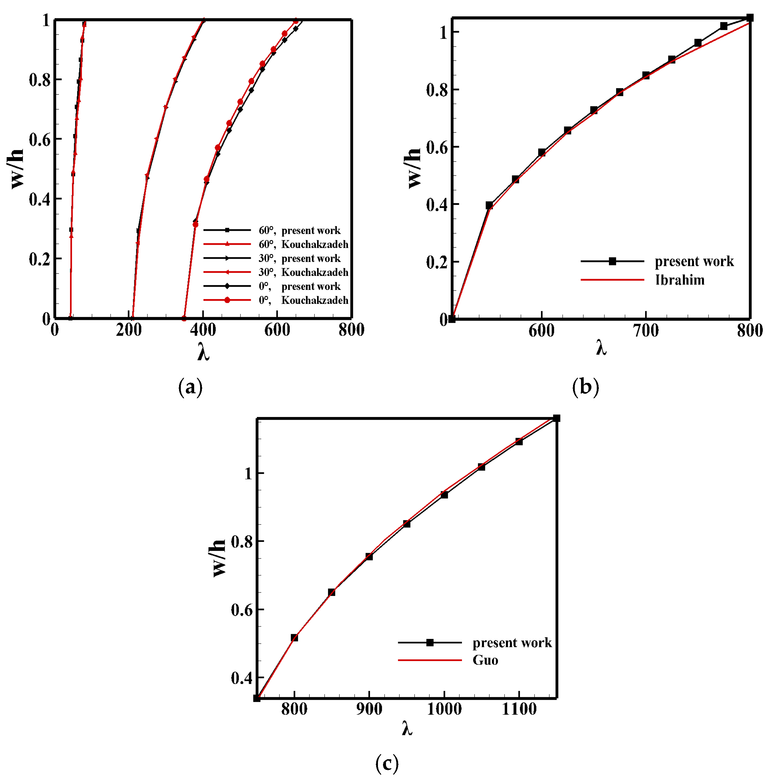
2.3. Code Validation

In the study of panel flutter, the maximum point of the LCO amplitude in the plates or laminates is more significant than other points [22], which is usually used as the monitor point. According to the numerical calculations, the monitor point is located at (0.75 a , 0.5 b ) in the case of α = 0 , and it is consistent with the conclusion in Ref. [22].
The following examples are selected for code verification. The results of Ref. [11] is reproduced by using a graphite–epoxy resin AS-3002 laminate (Figure 1a); take a / b = 1 / 20 , μ / M = ρ a / M ρ s h = 0.01 , E 11 / E 22 = 26.5 , G 12 = 1.184 E 22 , and υ 12 = 0.21 , where a is the length, b is the width, h is the thickness, μ is the mass ratio, and ρ s is the material density. Then, the results of Ref. [13] are reproduced by using a single-layer panel (Figure 1b); take a = b = 0.305   m , h = 0.00127   m , μ / M = 0.1 , E 1 = E 2 = 70   Gpa , G 12 = 26.9   Gpa , and υ = 0.3 . Furthermore, in order to verify the method in this paper where the yaw angle is non-zero, the results of Ref. [30] are reproduced by using another single-layer panel; take a = 0.381   m , b = 0.305   m , h = 0.00127   m , μ / M = 0.01 , E 1 = 155   Gpa , E 2 = 8.07   Gpa , G 12 = 4.55   Gpa , υ 12 = 0.22 , and ρ s = 1550   kg / m 3 . The boundary condition is simply supported in these cases, and the dimensionless dynamic pressure is defined as
λ = ρ U 2 a 3 D M 2 1
where U is the flow velocity and D is the bending stiffness of the reference material.
Figure 2a shows the comparison results of dimensionless displacement with Ref. [11] at different ply angles, and the maximum error is 6.1%. Figure 2b shows the comparison results of the dimensionless displacement of the single-layer panel with that of Ref. [13], and the maximum error is only 3.0%. Figure 2c shows the comparison between the dimensionless displacement with yaw angle and that in Ref. [30], and the maximum error is only 1.2%. Therefore, the comparison of the results (Figure 2) shows reasonable agreement, and these good agreements verify the developed method in predicting the critical dynamic pressure and LCO amplitude.
Many studies [5,11,15,30] show that the flutter characteristics for composite laminates have weaker regularity than that of the single-layer plates. In order to further understand the flutter characteristics of composite laminates, the effects of several key structural parameters will be studied in the next section.

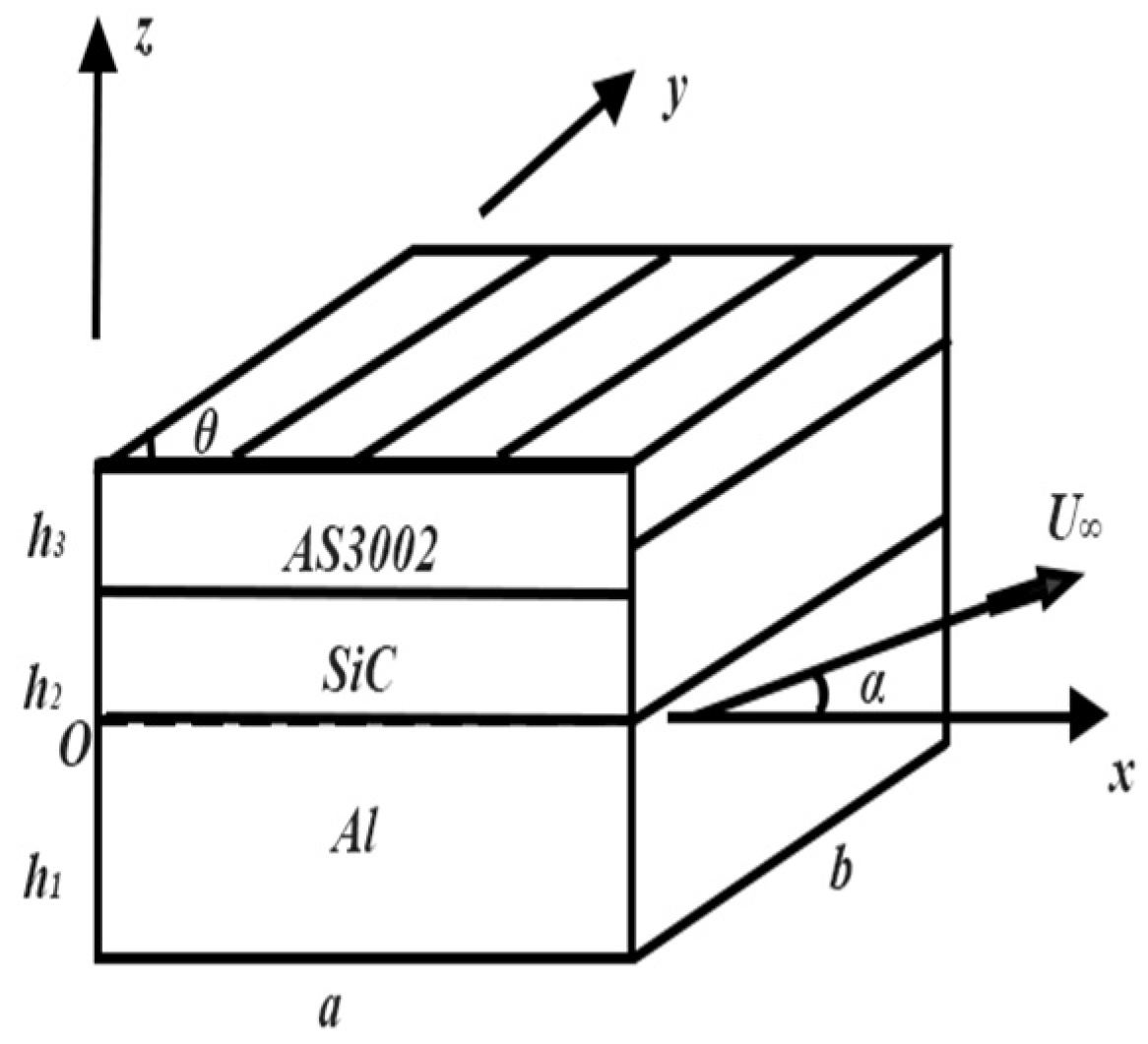
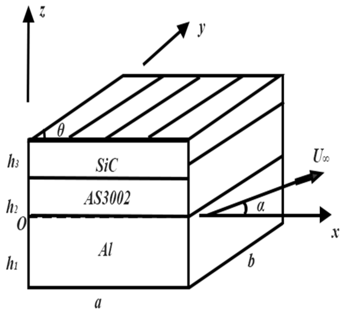
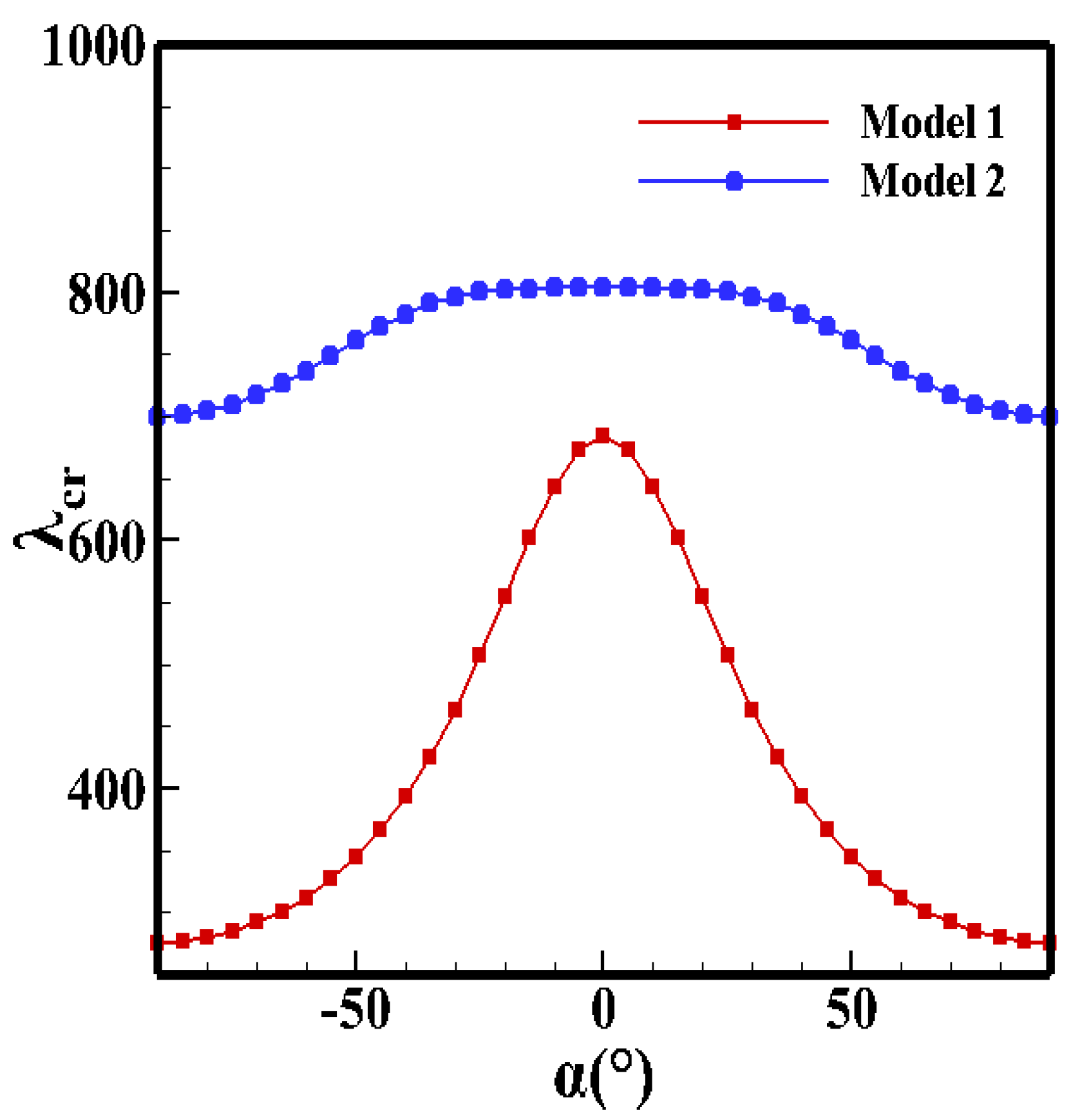
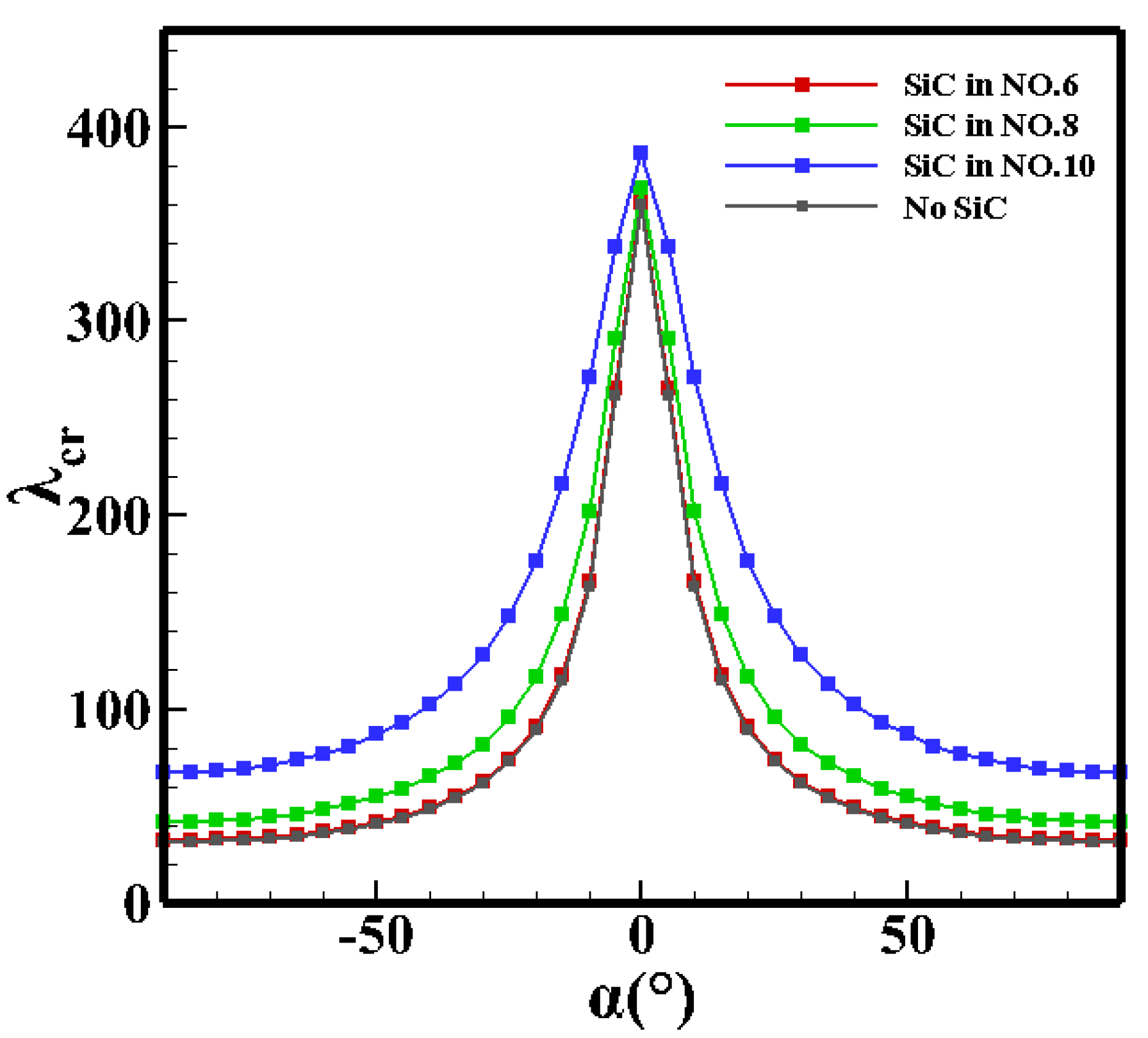
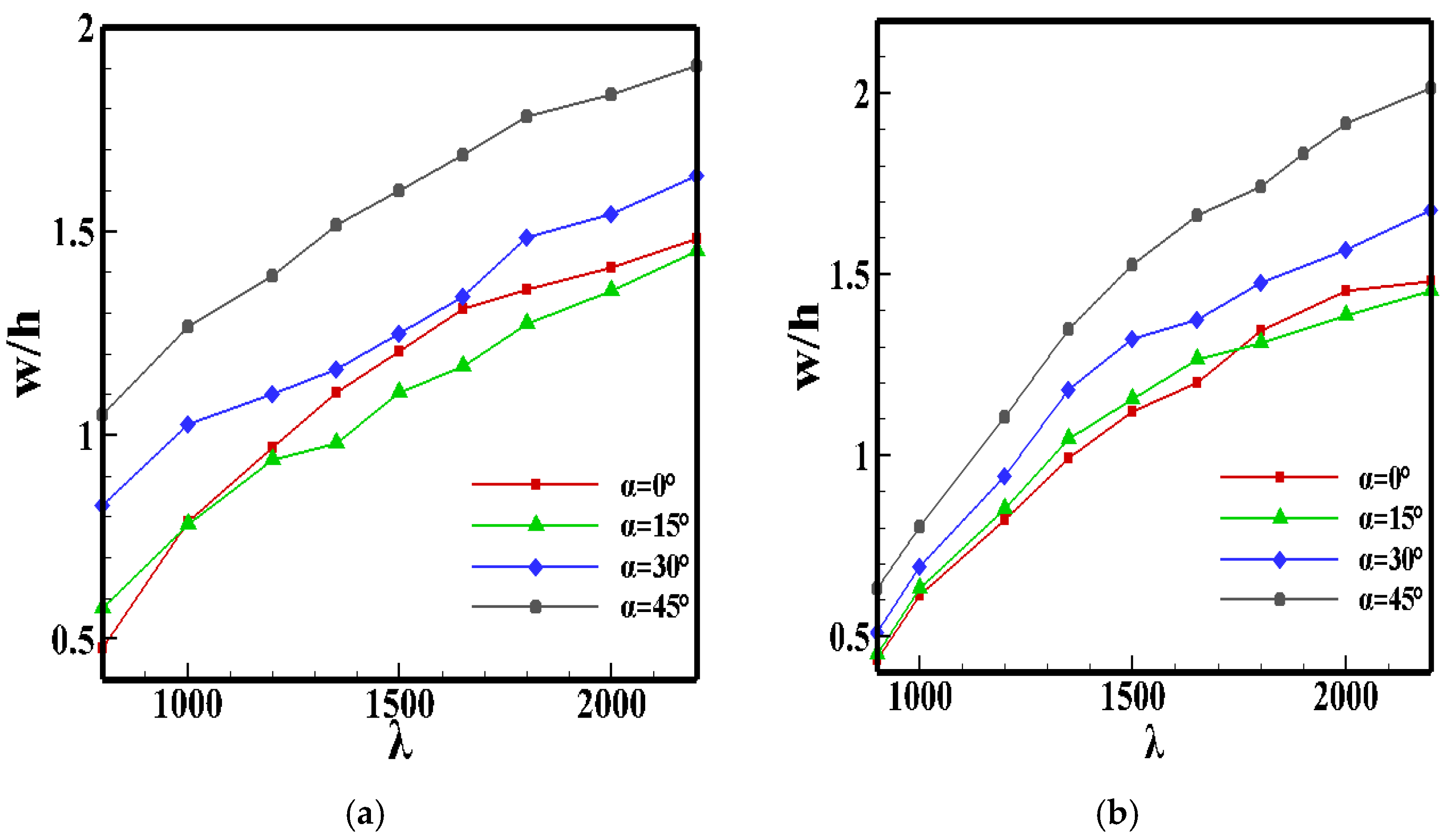
3. Numerical Results and Discussion

In this section, the composite laminated models are designed firstly. After obtaining the location of the monitor points, the influence of the stacking sequence, the thickness of each layer, and the fiber orientation on flutter characteristics are analyzed.
Model 1 and Model 2 are designed with three materials which are widely used in thin-walled structures on aircrafts, and they are shown in Figure 3 and Figure 4. With a large number of numerical calculations, all the maximum points of LCO amplitude with different yaw angles are obtained. The results are shown in Table 1, and they are used as monitor points in this section. Table 2 shows the mechanical properties of the materials.
The mechanical properties of these materials are shown in Table 2.
Using Model 1 and Model 2, the critical dynamic pressure and LCO amplitude of different stacking sequences, thickness ratios, and fiber orientations are calculated, and the flutter characteristics in hypersonic yawed flow are analyzed, especially the critical dynamic pressure and the LCO amplitude. Take a = b = 1   m , h 1 + h 2 + h 3 = h = 1 / 300 a , h 1 = 0.5 h , h 2 = h 3 = 0.25 h in Section 3.1 and Section 3.3. In order to study the influence of changing the thickness on the flutter characteristics, take h 1 = 0.5 h , h 2 + h 3 = 0.5 h in Section 3.2. In addition, the ply angle is zero in Section 3.1 and Section 3.2, and the fiber orientations in Section 3.3 are shown in Table 3 and Table 4.
The freestream Mach number is 5, ρ = 0.413   kg / m 3 , the specific heat ratio is 1.4, and all the laminates are simply supported. Since the stacking sequence and thickness of the aluminum material is not changed in Section 3.1 and Section 3.2 and the aluminum material is isotropic, it is not affected by the fiber orientation in the study of Section 3.3. Therefore, the bending stiffness of aluminum is used for calculating the dimensionless dynamic pressure.

3.1. Effect of Stacking Sequence

In this section, the influence of stacking sequence on the flutter characteristics of composite laminates is analyzed. Before showing the numerical results, we would like to first prove theoretically that positioning the material with a higher elastic modulus on the upper layer effectively increases the critical dynamic pressure, and the theoretical result will also be used for comparison purposes.
Since the stacking sequence is changed without adding new materials, the mass matrix is almost unchanged. In the stiffness matrix of Equation (11), K w w is dominant and the values of the other parts are small. If the nonlinear terms in K w w and other parts are ignored, only the terms containing D i j are kept (see Appendix A). For most materials, the greater the elastic modulus is, the larger the values of D i j are. In the theoretical analysis below, the thickness of each layer and the fiber orientations are assumed to be constant.
Consider two layers of composite laminates which have
0 < Q i j 1 Q i j 2 , 0 < z 1 < z 2
where z i is the height of the interface of each layer.
According to Equation (14), when the integral of z 2 is an increasing function, we can obtain
Q i j 2 z 1 z 2 z 2 d z + Q i j 1 0 z 1 z 2 d z Q i j 1 z 1 z 2 z 2 d z + Q i j 2 0 z 1 z 2 d z
where Q i j k is the elastic stiffness coefficient of each layer.
Therefore, the conclusion that positioning the material with a higher elastic modulus on the upper layer can obtain greater stiffness is proven using two-layer composite laminates.
Extending this to N-layer laminates, suppose that
0 < Q i j 1 Q i j 2 Q i j n , 0 < z 1 < z 2 < < z n < z n + 1
We need to prove that Equation (17) is the largest:
Q i j 1 z 1 z 2 z 2 d z + + Q i j k z k z k + 1 z 2 d z + + Q i j n z n z n + 1 z 2 d z
which is equivalent to proving that
Q i j 1 z 1 z 2 z 2 d z + Q i j 2 z 2 z 3 z 2 d z + + Q i j n z n z n + 1 z 2 d z Q i j k 1 z 1 z 2 z 2 d z + Q i j k 2 z 2 z 3 z 2 d z + + Q i j k n z n z n + 1 z 2 d z
where Q i j k k is the elastic stiffness coefficient of each layer in the random stacking sequence.
In the case of
Q i j 1 = Q i j k 1 , Q i j 2 = Q i j k 2 Q i j n = Q i j k n
Equation (18) is correct. For other cases, suppose that
Q i j k n Q max
The right side of Equation (18) can be written as
Q i j k 1 z 1 z 2 z 2 d z + + Q i j k k z k z k + 1 z 2 d z + + Q i j k n z n z n + 1 z 2 d z
In Equation (21), there must be
Q i j k k = Q i j n = Q max
After exchanging the order of Q i j k k and Q i j k n , a new formula is obtained:
Q i j k 1 z 1 z 2 z 2 d z + + Q i j k k z n z n + 1 z 2 d z + + Q i j k n z k z k + 1 z 2 d z
Subtracting Equation (23) from Equation (21), we can obtain
( Q i j k k Q i j k n ) ( z n z n + 1 z 2 d z z k z k + 1 z 2 d z ) 0
After performing the same operations on other items, the proof can be completed.
Therefore, placing the material with the larger elastic modulus on the upper layer of the laminates can obtain larger structural stiffness.
The three-layer laminated models (Figure 3 and Figure 4) are used for the calculation in this section. The results of the critical dynamic pressure with the yaw angle are shown in Figure 5.
Figure 5 shows that when the SiC material with the larger elastic modulus is placed on the top layer of the laminate (Model 2), the critical dynamic pressure is larger. This phenomenon shows that, regardless of the yaw angle, the stiffness of Model 2 is greater than that of Model 1, which is consistent with the theory proposed in this section.
As the verification, the single-layer panel shown in Figure 1b is divided into ten layers, and the geometric parameters are consistent with Ref. [13]. Then, the materials of the sixth, eighth, and tenth layers from the bottom are replaced with SiC, respectively, and the critical dynamic pressure with the yaw angle is calculated. Similarly, the laminate model shown in Figure 1a is adopted, the geometric parameters are consistent with Ref. [11], and the critical dynamic pressure with the yaw angle is calculated. The results are shown in Figure 6 and Figure 7.
As shown in Figure 6 and Figure 7, when the SiC layer is placed on the top of the laminate, the critical dynamic pressure is the largest, and it becomes smaller when the SiC layer is placed lower. This phenomenon is similar to that shown Figure 5.
The theoretical analysis and large number of simulation calculations show that the critical dynamic pressure is larger in the case where the material with higher stiffness is placed on the upper layer.
In the cases where flutter occurs, the large vibration amplitude will destroy the structure. Therefore, it is necessary to study the LCO amplitude of laminates.
Figure 8 shows that a large yaw angle will cause a larger LCO amplitude, and this phenomenon is not obvious when the yaw angle is small. Comparing Figure 8a,b, although the critical dynamic pressure of Model 2 is larger, with the increase in λ , the growth rate of the LCO amplitude is larger than that of Model 1. Therefore, changing the stacking sequence can only suppress the LCO amplitude within a certain range. In the case of large dynamic pressure ( λ 1350 ) , it is unable to suppress the LCO amplitude.

3.2. Effect of Thickness Ratio

In this section, the influence of the thickness ratio on the flutter characteristics of composite laminates is analyzed, and Model 1 and Model 2 are used for the study in this section. Numerical calculation is used for the analysis in this section. Taking different yaw angles, the critical dynamic pressure is calculated with the thickness of the SiC.
Figure 9 shows that the stiffness of the SiC in the direction perpendicular to the freestream flow is much larger than that of graphite–epoxy resin AS-3002. With the increase in the yaw angle, the elastic modulus of graphite–epoxy resin AS-3002 in the direction of the incoming flow decreases significantly, resulting in a rapid decrease in the critical dynamic pressure. Thus, in the case of large yaw angles, increasing the proportion of the SiC material is more effective in increasing the critical dynamic pressure than that of small yaw angles.
In addition, for the same yaw angle, the critical dynamic pressure of Model 2 is obviously larger than that of Model 1, which is consistent with the conclusion in Section 3.1.
Then, the influence of the thickness ratio on the LCO amplitude is studied. Model 2 is used in this section, and several typical thickness ratio parameters are selected.
According to Figure 10, with the increase in the thickness ratio of the SiC material, the LCO amplitude can be suppressed to a certain extent in cases of large yaw angles, but the effect is not obvious at small yaw angles. This phenomenon is similar to the mechanism of the critical dynamic pressure changing with the yaw angle in this section.

3.3. Effect of the Fiber Orientation

Large change rate of critical dynamic pressure with yaw angle may lead to aeroelastic instability, which is intolerable during flight. In this section, the influence of fiber orientation on the flutter characteristics of composite laminates is analyzed, and a fiber orientation of each layer is symmetrical to x a x i s is proposed to effectively improve the flight stability with the change in the yaw angle.
Due to the larger stiffness of Model 2, the difference in fiber orientation is difficult to cause the critical dynamic pressure changes significantly, which is not conducive to obtain the influence of fiber orientation intuitively. Therefore, Model 1 is used in this section, and the graphite–epoxy resin AS-3002 laminate (Figure 1a) is used for the verification. The considered fiber orientations are shown in Table 3 and Table 4, which are taken for the simulation.
The elastic modulus differences in anisotropic materials in different directions are large, leading the critical dynamic pressure sharply changed with the yaw angle (Mode 1 in Figure 11 and Figure 12). Therefore, we try to change the ply angle, increasing the maximum stiffness of each layer in different directions, so that the stiffness of the laminates in all directions is more balanced.
As shown in Figure 11, when the fiber orientation of each layer is symmetrical to x a x i s , as the fiber orientation angle increases, the curve of the critical dynamic pressure with the yaw angle becomes narrower, and alternating plying at 45 degrees and −45 degrees (Mode 9 and 10 in Table 3) achieves the best stability. Otherwise, the critical dynamic pressure will decrease significantly when the yaw angle is large. This phenomenon proves that the stiffness of the laminates is indeed more balanced in all directions, which improves the flight stability with the change in the yaw angle. Mode 2, Mode 5, and Mode 8 show the fiber orientations which are not symmetrical to x a x i s . In this case, the maximum critical dynamic pressure is not located at a zero yaw angle, which does not conform to the design concept. In addition, asymmetric fiber orientation and random modes will make the critical dynamic pressure unpredictable, which needs further study.
The results in Figure 12 show that Mode 9 and 10 in Table 4 achieve the best stability, and Mode 11 to 14 are unpredictable, which is similar to the results in Figure 11.

4. Conclusions

The flutter characteristics of three-dimensional composite laminates in hypersonic yawed flow are studied. The piston theory including the influence of the yaw angle is employed to compute the aerodynamic force, and Von-Karman’s large deflection theory is used to account for geometric nonlinearity. The governing equations are derived based on Hamilton’s principle, and the assumed mode method is used for discretization. Several laminated models are designed to study the effect of the stacking sequence, thickness, and fiber orientation on critical dynamic pressure and LCO amplitude. The conclusions are as follows:
(1) The material with the larger elastic modulus being placed on the upper layer can effectively improve the critical dynamic pressure, which is verified by theoretical analysis and numerical calculations. It can also suppress the LCO amplitude within a certain range, but the effect is not obvious in the case of large dynamic pressure.
(2) In cases of large yaw angles, increasing the thickness of the material with the larger elastic modulus can improve the critical dynamic pressure and suppress the LCO amplitude, but the effect is not obvious when the yaw angle is small.
(3) As the yaw angle changes continuously, the fiber orientation symmetry to x a x i s can make the stiffness of the laminate more balanced in all directions, and the flight stability can be improved. Asymmetric and randomly distributed fiber orientations result in more unpredictable flutter characteristics.
Although this paper discusses several specific laminated plate models, only the material properties are used. In theory, the conclusions in this paper can be extended to other aviation composite materials, and further research on this issue will require study in the future.

Author Contributions

Methodology, S.C.; software, S.C. and D.Z.; validation, S.C., T.G. and D.Z.; formal analysis, S.C. and J.W.; investigation, J.W.; resources, E.S.; data curation, S.C. and T.G.; writing—original draft preparation, S.C.; writing—review and editing, S.C. and D.Z.; visualization, J.W.; supervision, E.S.; project administration, J.W.; funding acquisition, T.G and D.Z. All authors have read and agreed to the published version of the manuscript.

Funding

This research was funded by the National Natural Science Foundation of China (Grant No. 12102187) and a project funded by the Priority Academic Program Development of Jiangsu Higher Education Institutions.

Data Availability Statement

Data are contained within the article.

Acknowledgments

This work is also partially supported by the High Performance Computing Platform of Nanjing University of Aeronautics and Astronautics.

Conflicts of Interest

The authors declare no conflicts of interest.

Appendix A

In Equation (9), the specific form of the mass matrix is
M u u = 0 a 0 b I 0 φ T φ d x d y
M u w = 0 a 0 b I 1 φ T φ x I 1 ( φ x ) T φ d x d y
M v w = 0 a 0 b I 1 φ T φ y I 1 ( φ x ) T φ d x d y
M w w = 0 a 0 b I 0 φ T φ + I 2 ( φ x ) T ( φ x ) + I 2 ( φ y ) T ( φ y ) d x d y
In Equations (A1)–(A4),
I 0 = k = 1 n ρ s k ( z k + 1 z k )
I 1 = 1 2 k = 1 n ρ s k ( z k + 1 2 z k 2 )
I 2 = 1 3 k = 1 n ρ s k ( z k + 1 3 z k 3 )
The specific form of the stiffness matrix is
K u u = 0 a 0 b A 11 ( φ x ) T ( φ x ) + A 66 ( φ y ) T ( φ y ) + A 16 ( φ y ) T ( φ x ) + A 16 ( φ x ) T ( φ y ) d x d y
K u v = 0 a 0 b A 12 ( φ x ) T ( φ y ) + A 66 ( φ y ) T ( φ x ) + A 16 ( φ x ) T ( φ x ) + A 26 ( φ y ) T ( φ y ) d x d y
K v v = 0 a 0 b A 22 ( φ y ) T ( φ y ) + A 66 ( φ x ) T ( φ x ) + A 26 ( φ x ) T ( φ y ) + A 26 ( φ y ) T ( φ x ) d x d y
K u w = 0 a 0 b A 11 2 ( φ x ) T ( φ x ) q w ( φ y ) + A 12 2 ( φ x ) T ( φ y ) q w ( φ y ) + A 16 2 ( φ y ) T ( φ x ) q w ( φ x ) + A 66 ( φ y ) T ( φ x ) q w ( φ y ) + A 16 ( φ x ) T ( φ x ) q w ( φ y ) + A 26 2 ( φ y ) T ( φ y ) q w ( φ y ) B 11 ( φ x ) T ( 2 φ x 2 ) B 12 ( φ x ) T ( 2 φ y 2 ) 2 B 16 ( φ y ) T ( 2 φ x 2 ) B 16 ( φ y ) T ( 2 φ x 2 ) B 26 ( φ y ) T ( 2 φ y 2 ) 2 B 66 ( φ y ) T ( 2 φ x y ) d x d y
K v w = 0 a 0 b A 22 2 ( φ y ) T ( φ y ) q w ( φ y ) + A 12 2 ( φ y ) T ( φ x ) q w ( φ x ) + A 66 ( φ x ) T ( φ x ) q w ( φ y ) + A 16 2 ( φ x ) T ( φ x ) q w ( φ x ) + A 26 2 ( φ x ) T ( φ y ) q w ( φ y ) + A 26 ( φ y ) T ( φ x ) q w ( φ y ) B 22 ( φ y ) T ( 2 φ y 2 ) B 12 ( φ y ) T ( 2 φ x 2 ) 2 B 66 ( φ x ) T ( 2 φ x y ) B 16 ( φ x ) T ( 2 φ x 2 ) B 26 ( φ x ) T ( 2 φ y 2 ) 2 B 26 ( φ y ) T ( 2 φ x y ) d x d y
K w u = 0 a 0 b A 11 ( φ x ) T q w T ( φ x ) ( φ x ) + A 11 ( φ y ) T q w T ( φ y ) ( φ x ) + A 66 ( φ x ) T q w T ( φ y ) ( φ y ) + A 66 ( φ y ) T q w T ( φ x ) ( φ y ) + A 12 ( φ y ) T q w T ( φ y ) ( φ x ) + A 16 ( φ x ) T q w T ( φ x ) ( φ y ) + A 16 ( φ x ) T q w T ( φ y ) ( φ x ) + A 16 ( φ y ) T q w T ( φ x ) ( φ x ) + A 26 ( φ y ) T q w T ( φ y ) ( φ y ) B 11 ( φ x ) T ( 2 φ x 2 ) B 12 ( φ x ) T ( 2 φ y 2 ) 2 B 16 ( φ y ) T ( 2 φ x 2 ) B 16 ( φ y ) T ( 2 φ x 2 ) B 26 ( φ y ) T ( 2 φ y 2 ) 2 B 66 ( φ y ) T ( 2 φ x y ) d x d y
K v w = 0 a 0 b A 22 ( φ y ) T q w T ( φ y ) ( φ y ) + A 12 ( φ x ) T q w T ( φ x ) ( φ y ) + A 66 ( φ x ) T q w T ( φ y ) ( φ x ) + A 66 ( φ y ) T q w T ( φ x ) ( φ x ) + A 16 ( φ x ) T q w T ( φ x ) ( φ x ) + A 26 ( φ y ) T q w T ( φ y ) ( φ x ) + A 26 ( φ x ) T q w T ( φ y ) ( φ y ) + A 26 ( φ y ) T q w T ( φ x ) ( φ y ) B 22 ( φ y ) T ( 2 φ y 2 ) B 12 ( φ y ) T ( 2 φ x 2 ) 2 B 66 ( φ x ) T ( 2 φ x y ) B 16 ( φ x ) T ( 2 φ x 2 ) B 26 ( φ x ) T ( 2 φ y 2 ) 2 B 26 ( φ y ) T ( 2 φ x y ) d x d y
K w w = 0 a 0 b D 11 ( 2 φ x 2 ) T ( 2 φ x 2 ) + D 22 ( 2 φ y 2 ) T ( 2 φ y 2 ) + D 12 ( 2 φ x 2 ) T ( 2 φ y 2 ) + D 12 ( 2 φ y 2 ) T ( 2 φ x 2 ) + D 66 ( 2 φ x y ) T ( 2 φ x y ) + 2 D 16 ( 2 φ x 2 ) T ( 2 φ x y ) + 2 D 16 ( 2 φ x y ) T ( 2 φ x 2 ) + 2 D 26 ( 2 φ y 2 ) T ( 2 φ x y ) + 2 D 26 ( 2 φ x y ) T ( 2 φ y 2 ) + A 11 2 ( φ x ) T ( φ x ) q w q w T ( φ x ) T ( φ x ) + A 22 2 ( φ y ) T ( φ y ) q w q w T ( φ y ) T ( φ y ) + A 12 2 ( φ x ) T ( φ x ) q w q w T ( φ y ) T ( φ y ) + A 12 2 ( φ y ) T ( φ y ) q w q w T ( φ x ) T ( φ x ) + A 66 ( φ x ) T ( φ x ) q w q w T ( φ y ) T ( φ y ) + A 66 ( φ y ) T ( φ y ) q w q w T ( φ x ) T ( φ x ) + 3 A 16 2 ( φ x ) T ( φ x ) q w q w T ( φ x ) T ( φ y ) + A 16 2 ( φ y ) T ( φ x ) q w q w T ( φ y ) T ( φ y ) + 3 A 26 2 ( φ y ) T ( φ y ) q w q w T ( φ y ) T ( φ x ) + A 26 2 ( φ x ) T ( φ y ) q w q w T ( φ y ) T ( φ y ) B 11 2 ( 2 φ x 2 ) T ( φ x ) q w ( φ x ) B 11 ( φ x ) T q w T ( φ x ) T ( 2 φ x 2 ) B 22 2 ( 2 φ y 2 ) T ( φ y ) q w ( φ y ) B 22 ( φ y ) T q w T ( φ y ) T ( 2 φ y 2 ) B 12 2 ( 2 φ y 2 ) T ( φ x ) q w ( φ x ) B 12 ( φ x ) T q w T ( φ x ) T ( 2 φ y 2 ) B 12 2 ( 2 φ x 2 ) T ( φ y ) q w ( φ y ) B 12 ( φ y ) T q w T ( φ y ) T ( 2 φ x 2 ) B 66 ( 2 φ x y ) T ( φ x ) q w ( φ y ) 2 B 66 ( φ x ) T q w T ( φ y ) T ( 2 φ x y ) 2 B 66 ( φ y ) T q w T ( φ x ) T ( 2 φ x y ) B 16 ( 2 φ x 2 ) T ( φ x ) q w ( φ y ) B 16 ( φ x ) T q w T ( φ y ) T ( 2 φ x 2 ) B 16 ( φ y ) T q w T ( φ x ) T ( 2 φ x 2 ) B 16 ( 2 φ x y ) T ( φ x ) q w ( φ x ) 2 B 16 ( φ x ) T q w T ( φ x ) T ( 2 φ x y ) B 26 ( 2 φ y 2 ) T ( φ x ) q w ( φ y ) B 26 ( φ x ) T q w T ( φ y ) T ( 2 φ y 2 ) B 26 ( φ y ) T q w T ( φ x ) T ( 2 φ y 2 ) B 26 ( 2 φ x y ) T ( φ y ) q w ( φ y ) 2 B 26 ( φ y ) T q w T ( φ y ) T ( 2 φ x y ) d x d y
A i j = z k z k + 1 Q i j d z
B i j = z k z k + 1 Q i j z d z
D i j = z k z k + 1 Q i j z 2 d z
where A i j is the tensile stiffness, B i j is the coupling stiffness, D i j is the bending stiffness, and Q i j is determined by the material properties.

References

  1. Meng, X.; Zhao, R.; Wang, Q.; Zhang, Z.; Wang, J. Fluid–Structure Interactions between Oblique Shock Trains and Thin-Walled Structures in Isolators. Aerospace 2024, 11, 482. [Google Scholar] [CrossRef]
  2. Wang, Y.-R.; Ma, Y.-H. Application of Deep Learning Models to Predict Panel Flutter in Aerospace Structures. Aerospace 2024, 11, 677. [Google Scholar] [CrossRef]
  3. Hasheminejad, S.M.; Aghayi Motaaleghi, M. Aeroelastic analysis and active flutter suppression of an electro-rheological sandwich cylindrical panel under yawed supersonic flow. Aerosp. Sci. Technol. 2015, 42, 118–127. [Google Scholar] [CrossRef]
  4. Li, J.; Narita, Y. Analysis and optimal design for supersonic composite laminated plate. Compos. Struct. 2013, 101, 35–46. [Google Scholar] [CrossRef]
  5. Shao, C.; Cao, D.; Xu, Y.; Zhao, H. Flutter and Thermal Buckling Analysis for Composite Laminated Panel Embedded with Shape Memory Alloy Wires in Supersonic Flow. Int. J. Aerosp. Eng. 2016, 2016, 8562716. [Google Scholar] [CrossRef]
  6. Zhou, J.; Xu, M.; Yang, Z.; Kłosowski, P. Nonlinear Flutter Response of Heated Curved Composite Panels with Embedded Macrofiber Composite Actuators. Adv. Mater. Sci. Eng. 2018, 2018, 3103250. [Google Scholar] [CrossRef]
  7. Qi, W.; Wang, M.; Tian, S. Effects of Mass Attachments on Flutter Characteristics of Thin-Walled Panels. Aerospace 2022, 9, 748. [Google Scholar] [CrossRef]
  8. Dowell, E.H. Nonlinear oscillations of a fluttering plate. AIAA J. 1966, 4, 1267–1275. [Google Scholar] [CrossRef]
  9. Dowell, E.H. Nonlinear oscillations of a fluttering plate. II. AIAA J. 1967, 5, 1856–1862. [Google Scholar] [CrossRef]
  10. Ventres, C.S.; Dowell, E.H. Comparison of theory and experiment for nonlinear flutter of loaded plates. AIAA J. 1970, 8, 2022–2030. [Google Scholar] [CrossRef]
  11. Kouchakzadeh, M.A.; Rasekh, M.; Haddadpour, H. Panel flutter analysis of general laminated composite plates. Compos. Struct. 2010, 92, 2906–2915. [Google Scholar] [CrossRef]
  12. Shiau, L.-C.; Lu, L.-T. Nonlinear flutter of two-dimensional simply supported symmetric composite laminated plates. J. Aircr. 1992, 29, 140–145. [Google Scholar] [CrossRef]
  13. Ibrahim, H.H.; Yoo, H.H.; Lee, K.-S. Supersonic Flutter of Functionally Grated Panels Subject to Acoustic and Thermal Loads. J. Aircr. 2009, 46, 593–600. [Google Scholar] [CrossRef]
  14. Xie, D.; Xu, M.; Dowell, E.H. Proper Orthogonal Decomposition Reduced-Order Model for Nonlinear Aeroelastic Oscillations. AIAA J. 2014, 52, 229–241. [Google Scholar] [CrossRef]
  15. Zhou, K. Nonlinear dynamic analysis and vibration suppression on the composite laminated plates with general boundary conditions in supersonic airflow. Thin-Walled Struct. 2023, 190, 110956. [Google Scholar] [CrossRef]
  16. Amirzadegan, S.; Dowell, E.H. Correlation of Experimental and Computational Results for Flutter of Streamwise Curved Plate. AIAA J. 2019, 57, 3556–3561. [Google Scholar] [CrossRef]
  17. Arani, A.G.; Kiani, F.; Afshari, H. Aeroelastic Analysis of Laminated FG-CNTRC Cylindrical Panels Under Yawed Supersonic Flow. Int. J. Appl. Mech. 2019, 11, 1950052. [Google Scholar] [CrossRef]
  18. Singha, M.K.; Mandal, M. Supersonic flutter characteristics of composite cylindrical panels. Compos. Struct. 2008, 82, 295–301. [Google Scholar] [CrossRef]
  19. Lin, H.; Cao, D.; Xu, Y. Vibration characteristics and flutter analysis of a composite laminated plate with a store. Appl. Math. Mech. 2017, 39, 241–260. [Google Scholar] [CrossRef]
  20. Zhou, K.; Huang, X.; Tian, J.; Hua, H. Vibration and flutter analysis of supersonic porous functionally graded material plates with temperature gradient and resting on elastic foundation. Compos. Struct. 2018, 204, 63–79. [Google Scholar] [CrossRef]
  21. Chai, Y.; Li, F.; Song, Z. Nonlinear vibrations, bifurcations and chaos of lattice sandwich composite panels on Winkler–Pasternak elastic foundations with thermal effects in supersonic airflow. Meccanica 2019, 54, 919–944. [Google Scholar] [CrossRef]
  22. Meng, X.; Ye, Z.; Ye, K.; Liu, C. Analysis on location of maximum vibration amplitude in panel flutter. Proc. Inst. Mech. Eng. Part G J. Aerosp. Eng. 2019, 234, 457–469. [Google Scholar] [CrossRef]
  23. Abdukhakimov, F.A.; Vedeneev, V.V. Effect of yaw angle on flutter of rectangular plates at low supersonic speeds. AIAA J. 2022, 60, 4256–4266. [Google Scholar] [CrossRef]
  24. Moreira, J.A.; Moleiro, F.; Araújo, A.L.; Pagani, A. Analytical modeling of panel flutter and active control in supersonic variable stiffness composite laminates. Mech. Adv. Mater. Struct. 2022, 30, 930–944. [Google Scholar] [CrossRef]
  25. Mozaffari-Jovin, S.; Firouz-Abadi, R.D.; Roshanian, J. Flutter of wings involving a locally distributed flexible control surface. J. Sound Vib. 2015, 357, 377–408. [Google Scholar] [CrossRef]
  26. Vindigni, C.R.; Mantegna, G.; Orlando, C.; Alaimo, A.; Berci, M. A refined aeroelastic beam finite element for the stability analysis of flexible subsonic wings. Comput. Struct. 2025, 307, 107618. [Google Scholar] [CrossRef]
  27. Jansson, S.; Deve, H.E.; Evans, A.G. The anisotropic mechanical-properties of a TI matrix composite reinforced with SiC fibers. Metall. Trans. A-Phys. Metall. Mater. Sci. 1991, 22, 2975–2984. [Google Scholar] [CrossRef]
  28. Paley, M.; Aboudi, J. Viscoplastic bifurcation buckling of plates. AIAA J. 1991, 29, 627–632. [Google Scholar] [CrossRef]
  29. Muc, A.; Flis, J. Free vibrations and supersonic flutter of multilayered laminated cylindrical panels. Compos. Struct. 2020, 246, 112400. [Google Scholar] [CrossRef]
  30. Guo, X.; Mei, C. Using Aeroelastic Modes for Nonlinear Panel Flutter at Arbitrary Supersonic Yawed Angle. AIAA J. 2003, 41, 272–279. [Google Scholar] [CrossRef]
Figure 1. Models for validating code. (a) Graphite–epoxy resin AS-3002 laminate in Ref. [11]. (b) Single-layer panel.
Aerospace 12 00174 g001
Figure 2. Present results compared with other studies. (a) Comparing the present study with the results of Ref. [11]. (b) Comparing the present study with the results of Ref. [13]. (c) Comparing the present study with the results of Ref. [30] ( α = 40 ).
Aerospace 12 00174 g002
Figure 3. Model 1.
Figure 3. Model 1.
Aerospace 12 00174 g003
Figure 4. Model 2.
Figure 4. Model 2.
Aerospace 12 00174 g004
Figure 5. Critical dynamic pressure of the Models 1 and 2.
Aerospace 12 00174 g005
Figure 6. Critical dynamic pressure of the aluminum alloy plate.
Aerospace 12 00174 g006
Figure 7. Critical dynamic pressure of the graphite–epoxy resin AS-3002 laminate.
Aerospace 12 00174 g007
Figure 8. LCO amplitude at different yaw angles. (a) Model 1; (b) Model 2.
Aerospace 12 00174 g008
Figure 9. Critical dynamic pressure at different yaw angles. (a) Model 1; (b) Model 2.
Aerospace 12 00174 g009
Figure 10. LCO amplitude of Model 2 at different yaw angles. (a) α = 0 ; (b) α = 15 ; (c) α = 30 ; (d) α = 45 .
Aerospace 12 00174 g010
Figure 11. Critical dynamic pressure of Model 1 in different modes. (a) Modes 1 to 4. (b) Modes 5 to 7. (c) Modes 8 to 10. (d) Modes 11 to 14.
Aerospace 12 00174 g011
Figure 12. Critical dynamic pressure of the graphite–epoxy resin AS-3002 laminate in different modes. (a) Modes 1 to 4. (b) Modes 5 to 7. (c) Modes 8 to 10. (d) Modes 11 to 14.
Aerospace 12 00174 g012
Table 1. Monitor points with different yaw angles.
Yaw Angle (deg)0153045
Monitor point(0.75  a , 0.5  b )(0.74  a , 0.56  b )(0.72  a , 0.63  b )(0.70 a , 0.70  b )
Table 2. Mechanical properties of materials.
Material E 1 / E 2 G 12 ( Gpa ) υ 12 ρ ( kg / m 3 )
Al1.00026.9000.3002700
Graphite–Epoxy
AS-3002
26.5008.9360.2101600
SiC1.16962.9000.2703200
Table 3. Fiber orientations of Model 1.
Mode/Layer 1234567891011121314
Al 00000000000000
SiC015−151530−303045−45455820−407
AS300201515−153030−304545−4524−39−5746
Table 4. Fiber orientations of the graphite–epoxy resin AS-3002 laminate.
Mode/Layer1234567891011121314
1015−151530−303045−454559−3−42−19
201515−153030−304545−45−56−531955
3015−151530−303045−45454722251
401515−153030−304545−4550−5557−54
5015−151530−303045−454536−521829
601515−153030−304545−45−49336−28
7015−151530−303045−4545−29−49−6−9
801515−153030−304545−45−2038−86
9015−151530−303045−454522183954
1001515−153030−304545−45−4427−50−10
Disclaimer/Publisher’s Note: The statements, opinions and data contained in all publications are solely those of the individual author(s) and contributor(s) and not of MDPI and/or the editor(s). MDPI and/or the editor(s) disclaim responsibility for any injury to people or property resulting from any ideas, methods, instructions or products referred to in the content.

