1. Introduction
Unmanned aerial vehicles (UAVs), developed from manned aircraft, are reusable airborne systems that operate without onboard pilots. They are increasingly employed in a variety of engineering applications, such as inspection [
1], harvesting [
2], surveillance [
3], crop monitoring [
4], precision agriculture [
5], and remote sensing [
6]. Currently, aerial platforms involved in long-duration flight missions face significant challenges due to limitations in battery technology. In contrast, tethered UAVs can circumvent these constraints by deriving power from ground-based sources. Tethered UAVs are also applicable for payload transportation using single or multiple drones. A defining characteristic of tethered UAVs is their reliance on ground power to supply electricity to the UAV and its ancillary systems [
7]. Tethered UAV systems can be categorized based on their flight platforms into two types: the first type comprises tethered rotorcraft UAV systems that utilize rotor-based platforms for extended aerial endurance, and the second type consists of tethered fixed-wing UAV systems, where fixed-wing drones loiter in the air to maintain a stationary position within a defined area [
8].
Tethered UAVs offer extended aerial endurance compared to conventional UAVs and have experienced significant global development, particularly in multi-rotor configurations. For example, Israel’s Stark Aerospace developed the Hover Lite, which features a hovering light and four external propellers for rotational control [
9]. The U.S. military’s Tether Eye project, funded by the Office of Counterterrorism Technology Support, is utilized for intelligence, surveillance, and reconnaissance, achieving altitudes of to 150 feet and providing panoramic, all-weather views through a tethered automated system. CyPhy Industries, in collaboration with the U.S. military, introduced the Extreme Access Pocket Flyer, an interference-resistant UAV designed for confined spaces such as collapsed buildings and tunnels. This UAV can track explosive devices and monitor areas without radio frequency control, with a tether range of 400 feet. Additionally, Drone Aviation Corp. launched “Bolt”, a heavy-duty tethered UAV with enhanced payload capacity and altitude, aimed at military and security applications including patrols, embassy security, fleet escort, border control, crowd management, and search and rescue operations [
4]. In recent years, domestically developed tethered rotorcraft UAVs have also advanced, with several mature products emerging. Examples include Dagong Technology’s DG-M and DG-X series of tethered UAVs, which achieve maximum hovering altitudes of 100–300 m, carry payloads up to 20 km, and withstand wind speeds up to level six. Additionally, Zhuoying Intelligent has developed a six-axis, twelve-rotor tethered firefighting UAV capable of carrying up to 30 km, reaching heights of 150 m, sustaining firefighting operations for up to eight hours, and withstanding wind conditions up to level seven. According to the review by Miguel Nakajima [
8], the number of research articles on tethered unmanned systems increased from 100 to 600 between 2017 and 2022. revealing that tethered fixed-wing UAVs constitute a significantly smaller percentage compared to tethered rotorcraft UAVs. This disparity indicates that the technology for tethered rotorcraft UAVs has become increasingly mature, with most research focusing on payload expansion and application areas. In contrast, the field of tethered fixed-wing UAVs offers a wide array of research opportunities, including but not limited to aerodynamic design, control system development, dynamic modeling, and pattern recognition. Additionally, tethered fixed-wing UAVs typically achieve greater flight altitudes and higher speeds than their tethered rotorcraft counterparts, making control research for tethered fixed-wing UAVs both more challenging and more significant.
Compared to traditional rotorcraft UAVs, fixed-wing UAVs possess superior aerodynamic characteristics, enabling them to achieve greater payload capacities and longer endurance times under the same power conditions. The increased payload capacity allows tethered fixed-wing UAVs to attain higher flight altitudes and accommodate a wider variety of payloads, thereby expanding their potential application scenarios. These applications include signal relaying, airspace monitoring, and defense, among others, which hold substantial promise. Furthermore, tethered fixed-wing UAVs offer two major advantages over tethered rotorcraft UAVs: their loitering mode allows them to cover a larger area, and they exhibit better wind resistance. Although tethered fixed-wing UAVs cannot match the altitude capabilities of tethered balloons, they provide higher controllability compared to tethered balloons. This enhanced controllability is particularly beneficial when carrying payloads that require high stability, thereby improving their overall performance in such applications.
Over the past decades, airborne wind energy research has shifted from diverse prototypes to flight control strategies, with tethered fixed-wing UAVs emerging as a promising solution [
10]. Compared to soft kites, these UAVs offer higher aspect ratios and superior aerodynamic efficiency. Studies on tethered fixed-wing UAVs have covered system design, dynamic modeling, and control optimization [
11]. Vander Lind analyzed aspect ratio and airfoil selection, identifying optimal flight speeds for maximizing lift. Vimalakanthan et al. conducted CFD simulations, revealing discrepancies between SU2 and OpenFOAM solvers in 3D force predictions [
12]. De Lellis et al. demonstrated that slight aerodynamic modifications enhance power generation [
13]. Control strategies have also advanced significantly. Ruiterkamp and Sieberling developed waypoint-based lateral control [
14], while Bauer and Kennel optimized UAV designs using genetic algorithms, proving that biplanes outperform monoplanes [
15]. Rapp and Schmehl introduced a nonlinear control framework, validating its robustness under turbulence [
16]. Cobb and Barton proposed iterative learning for refining trajectory tracking [
17]. These studies highlight the advantages of tethered fixed-wing UAVs in airborne wind energy applications, emphasizing their potential for efficient power generation and stable flight control.
This paper focuses on designing a tethered fixed-wing unmanned aerial vehicle (UAV) system, developing a corresponding simulation model, and validating the design through actual flight tests. The design process includes selecting aerodynamic structures, propulsion systems, and tether management to ensure optimal performance and reliability under tethered conditions. A comprehensive simulation model was developed to accurately capture the UAV’s flight dynamics and tether interactions, aiding in the analysis and optimization of control strategies specifically for tethered operations.
Following the simulation, a physical prototype was constructed and tested in a controlled environment to validate the simulation results. Flight experiments were conducted to assess the UAV’s stability, maneuverability, and endurance, as well as the effectiveness of the tethered system in sustaining prolonged aerial operations. The results demonstrate that the designed system can maintain stable flight and precise trajectory tracking, highlighting the feasibility of tethered fixed-wing UAVs for extended-duration missions.
2. System Design
Tethered rotorcraft UAVs typically consist of a flight platform, data link, and ground station [
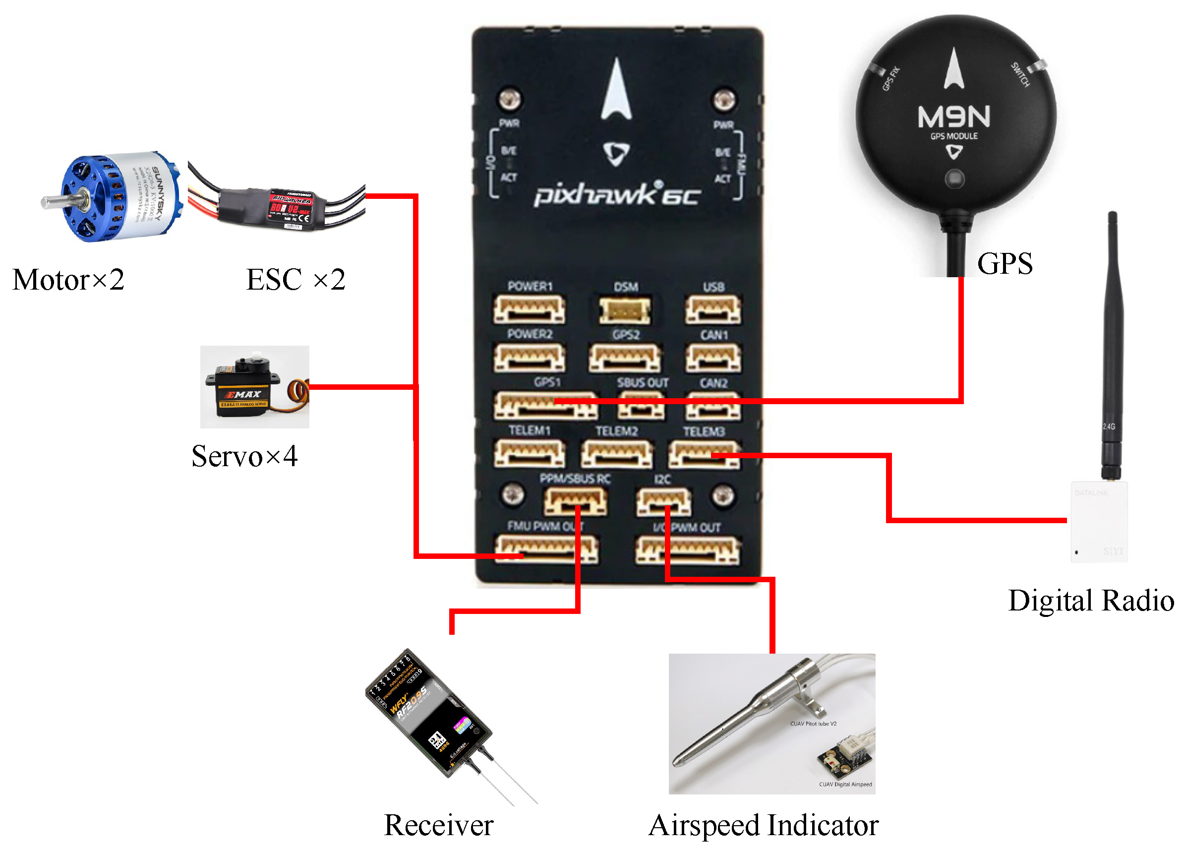
18]. Similarly, a tethered fixed-wing UAV system can be divided into three main components: the flight system, ground station system, and power system. The flight system includes the flight platform, sensors, flight control computer, data transmission radio, and other components. The flight platform is an electric motor-driven fixed-wing UAV that collects various parameters during flight through its sensors. The flight control computer utilizes these parameters to manage the operation of the platform. In considering that the operational range of the tethered fixed-wing UAV is too large and optical fibers cannot withstand sharp bends, along with the mass limitations associated with optical fiber switches, the wireless transmission of control signals was chosen for the experimental setup to reduce the weight of the UAV. Consequently, tethering was not used as the medium for transmitting control signals. Data are transmitted back to the ground computer via a data transmission radio for the real-time monitoring of the platform status.
The ground station system comprises a ground computer, winch, motor, and other equipment. The ground computer communicates with the flight platform through a digital radio, sends mission commands, and uses the motor to manage the deployment and retrieval of the tether.
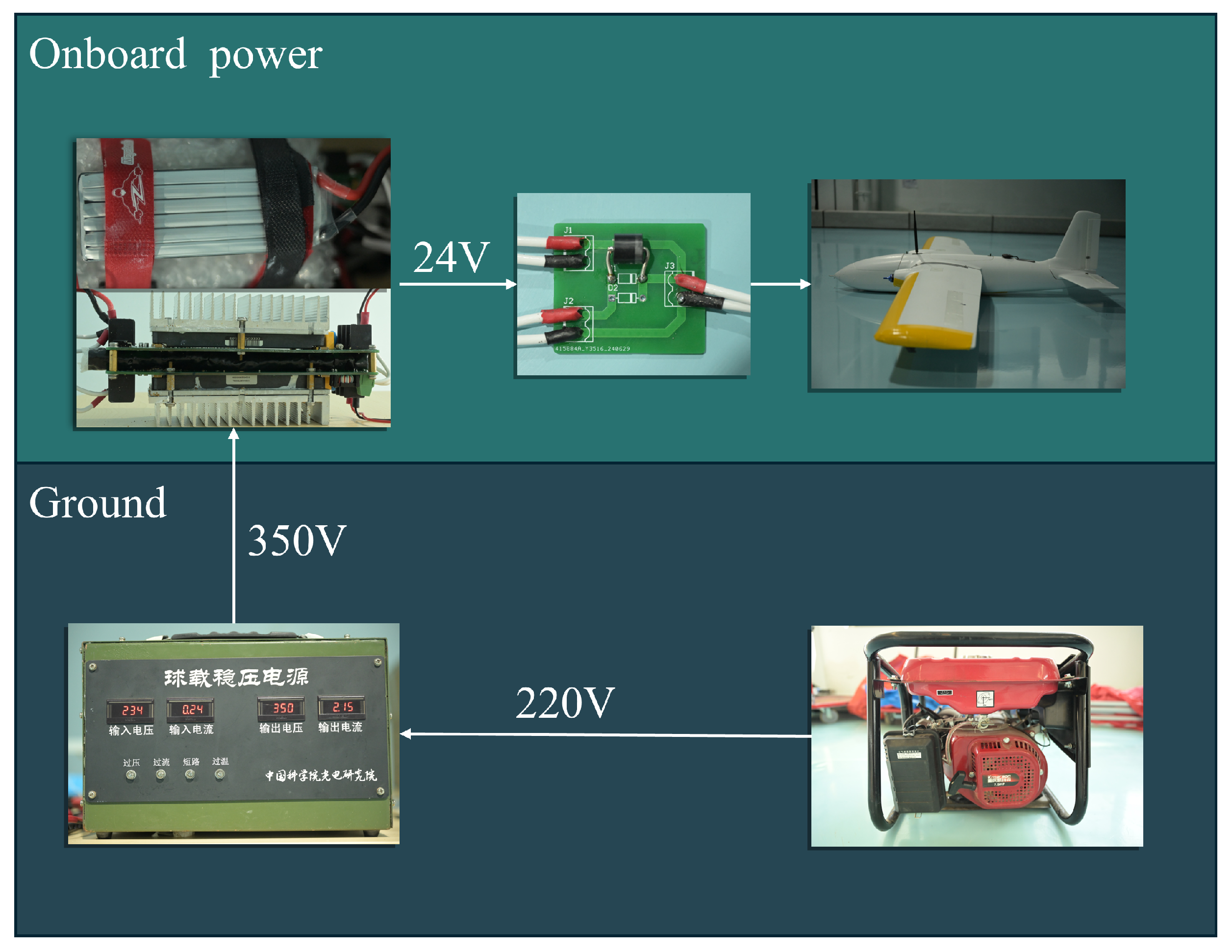
The power system must include a boost rectification module to ensure the normal operation of ground components by adapting to a 220-volt AC power grid. This module converts grid power into high-voltage DC power, which is transmitted through the tether, significantly reducing energy loss. Upon reaching the UAV, the electrical energy is converted to the operating voltage of the flight platform through a step-down module to ensure its proper functioning.
Figure 1 illustrates the system architecture.
3. System Simulation Model
This study presents a model designed to simulate tethered fixed-wing unmanned aerial vehicle (UAV) systems, thereby facilitating the subsequent validation of controller performance. The architecture of the simulation model is illustrated in
Figure 2. The flight controller generates specified control surface angles and throttle settings tailored for trajectory tracking tasks, which are subsequently used to calculate the forces and moments experienced by the aircraft.
In the tether subsystem, the winch controller produces torque setpoints that are input into the winch dynamic model to determine the winch’s rotational angles, thereby deriving the tether length. Based on the determined tether length, the tether mass point model, in conjunction with optimization methods, is employed to calculate the tether tension at the aircraft end. In utilizing the calculated forces and moments received by the aircraft, the state information of the aircraft can be accurately determined.
3.1. UAV Modeling
This section begins with the analysis of a small fixed-wing unmanned aerial vehicle (UAV) prototype, examining its structure and layout, and subsequently developing a dynamic model for a small twin-engine fixed-wing UAV. Initially, several assumptions regarding the flight process of the fixed-wing aircraft are made [
19]:
Rigid Body Assumption: The UAV is modeled as a rigid body with constant mass;
Inertial Reference Frame: The ground is assumed to constitute an inertial reference frame;
Flat Ground Approximation: The curvature of the ground is neglected, treating the ground as a flat plane;
Constant Gravitational Acceleration: Gravitational acceleration is presumed to remain unchanged with variations in flight altitude;
The tether attachment point is located at the aircraft’s center of mass, thereby generating force without exerting a net torque.
Based on the aforementioned assumptions, Newton’s second law can be applied within an inertial reference frame to formulate the aircraft’s translational motion under the influence of the resultant external force and its rotational motion under the influence of the resultant external moment,
where
is the matrix of aircraft inertia. Since fixed-wing UAVs are nearly symmetric about the xz-plane of the body frame,
and
are zero.
and
denote the angular velocity and velocity in the body-fixed coordinate system, respectively.
The resultant external force is given by
where
denotes aerodynamic forces,
is tether tension,
is the position of UAV,
l is the length of tether,
is gravity, and
is motor thrust
Further decomposition of the velocity and angular velocity in the body-fixed coordinate system yields the set of force equations and the set of moment equations.
u,
v, and
w denote the components of the aircraft’s velocity in the body-fixed coordinate system, while
p,
q, and
r represent the components of angular velocity.
where coefficients
,
,
,
,
,
,
,
, and
are defined as
Next, the rotational motion of the aircraft about its center of mass is established. Based on
Figure 3, the relationships between the rates of the attitude angles and the three angular velocity components in the body-fixed coordinate system can be formulated, thereby yielding the kinematic equations.
,
, and
are the roll, pitch, and yaw angle, respectively.
The lift force
L, drag force
D, side force
Y, roll moment
, pitch moment
M, and yaw moment
N acting on the aircraft during flight are modeled as follows. First, the aerodynamic forces are given by
where
is the dynamic pressure,
is the air density,
is the reference wing area, and
and
are the lift coefficient, drag coefficient, and side force coefficient, respectively.
The moments are represented as
where
and
are the rolling, pitching, and yawing moments, respectively.
b is the wingspan, and
is the average aerodynamic chord length.
The overall lift coefficient, drag coefficient, side force coefficient, and pitching, rolling, and yawing moment coefficients are given by
where
and
are the deflection angles of the ailerons, elevators, and rudders, respectively.
and
are the non-dimensionalized roll and yaw rates. To ensure the success of the experiment, it is necessary to guarantee the static stability of the UAV. Therefore, the longitudinal static stability derivative
, lateral static stability derivative
, and directional static stability derivative
need to be assessed. The UAV is considered to have static stability when the following conditions are met:
,
and
[
19].
In summary, a nonlinear mathematical model of a fixed-wing unmanned aerial vehicle can be derived based on the navigation equation, the kinematic equation, and the dynamic equation:
where
represents the UAV’s state variables, and
represents the UAV’s control inputs.
Since the operational state of the tethered fixed-wing UAV is steady circling, the steady-flight condition is selected as the equilibrium state. The nonlinear equations of the UAV are linearized using small perturbation theory [
19], where
represents the UAV nonlinear system and consists of
. The steady state corresponds to a particular solution of nonlinear system
In the steady circling state, the roll rate
and pitch rate
are both zero, while the yaw rate
remains constant. In carrying out a Taylor expansion of each nonlinear equation in the system, we obtain
In applying the small perturbation assumption, the quadratic and higher-order terms in the Taylor expansion are neglected, yielding the following result:
For fixed-wing unmanned aerial vehicles (UAVs), aerodynamic forces and moments are relatively clearly decomposed based on the airflow coordinate system. Therefore, the kinematic equations are transformed into state equations in terms of airspeed
, angle of attack
, and sideslip angle
. The airspeed
, angle of attack
, and sideslip angle
can be defined as follows:
Upon obtaining the linearized state-space equations, it is observed that the longitudinal and lateral dynamics of the fixed-wing unmanned aerial vehicle (UAV) are decoupled. Consequently, we decouple the lateral and longitudinal motions of the fixed-wing UAV to simplify the controller design process.
and
are state values of the UAV.
and
are control input of acutators. Specifically, we define the state variables and input variables as follows:
where
,
,
,
,
, and
are specifically represented as
where
,
, and
represent the desired airspeed, pitch angle, and angle of attack.
is gravitational acceleration.
The force linearization coefficients and moment linearization coefficients above are shown in
Table 1 and
Table 2.
In order to facilitate system identification using discrete data in the subsequent system identification process, the continuous-state space equations are discretized, yielding
where
,
,
,
.
3.2. UAV System Identification
This study employed system identification to determine the aerodynamic parameters of the unmanned aerial vehicle (UAV) [
20]. The excitation signals used for identification are the actual flight controller inputs during flight operations, specifically
(elevator deflection),
(throttle),
(aileron deflection), and
(rudder deflection). Sensor data, sampled at different frequencies, were utilized as the state inputs of the aircraft. Subsequently, parameter identification was conducted using the Recursive Least Squares (RLS) method [
21].
Building upon the previously derived linearized state-space model, input–output pairs were constructed to facilitate system identification. This methodology involves defining specific control inputs and observing the corresponding system outputs, thereby capturing the dynamic behavior of the fixed-wing unmanned aerial vehicle (UAV). By systematically applying various control inputs and recording the resultant outputs, a comprehensive dataset was generated that reflects the UAV’s response under different operating conditions.
Define the longitudinal inputs as
and the output as
. The model definition for system identification is presented in the equation. The objective of linear regression is to determine the parameter
such that the error
between the model’s predicted output and the actual output is minimized.
where
k represents the current time step, and
i denotes the
i-th time step from the initial time to the current time step.
Estimate the parameter
by minimizing the objective function
. The objective function is defined as
The specific recursive process is as follows: first, define the residual as
The parameter update formula is defined as
where
is a matrix representing the weight for updating parameters at the current time step, defined as
The gain matrix
can be calculated using the covariance matrix
from the previous time step and the current input vector
. Subsequently, the update formula for the covariance matrix is given by
Through the aforementioned update process, the system identification of the UAV’s linearized parameters can be carried out, with the lateral process being identical.
3.3. Tether Modeling
Firstly, the tether mass point model is introduced by modeling the tether as a series of spring-mass points [
22]. In the application of tethers for tethered unmanned aerial vehicles (UAVs), the influence of the tether’s bending stiffness can be neglected. Consequently, a model is developed in which the tether is represented as a sequence of mass points connected by frictionless hinges and massless segments.
Figure 4 illustrates the tether configuration of a fixed-wing tethered UAV during flight, where the position vector from the origin to the i-th mass point is defined as
, the position vector of the aircraft-end mass point is denoted as
, and the
i-th mass point is represented by
[
23].
Performing a force analysis on the
i-th mass point yields its equation of motion as
where
represents the gravitational force on the i-th mass point,
denotes the drag force experienced by the i-th tether segment, and
and
are the tensions exerted by the
i-th segment on the (
)-th segment and by the (
)-th segment on the
i-th segment, respectively.
The definition of the drag coefficient is presented in Equation (
37), where the dynamic pressure is
. The cross-sectional area of the tether is defined as
, where
d is the radius of the tether,
is the length of the i-th segment, and
is the normal velocity of the i-th segment. The tether tension for the i-th segment can be computed using
where
in the equation is defined as the difference between the velocity of the i-th mass point and the wind speed
at the current altitude, representing the airspeed of the i-th mass point:
Each segment has an initial length
and a mass
, and
L,
N, and
represent the current tether length, the number of mass points, and the linear density of the tether, respectively.
During each simulation step, the tether is assumed to behave as a rigid body, allowing the approximation of the tether’s angular velocity
and the velocity
and acceleration of
’s i-th mass point to be calculated as
After defining the tether model in
Section 3.3, it is not possible to obtain the tensions at the ground or aircraft ends of the tether as initial values. Consequently, the shape and tension of the tether cannot be directly calculated. Therefore, an optimization algorithm is employed to approximate the tether’s shape and tension. Common methods include classical approaches such as the Gauss–Newton, Gradient Descent, and Levenberg–Marquardt (LM) methods. In this study, the Dogleg algorithm is utilized to optimize the tether model. The Dogleg algorithm is a type of trust region method [
24].
Compared to line search methods, the Dogleg algorithm’s primary feature is its ability to determine a locally optimized value within a certain constraint range (typically by limiting the iteration step size) using a small number of steps. Relative to other methods, the Dogleg algorithm offers advantages such as rapid convergence, strong adaptability, the absence of a requirement for second-order derivatives, and controllability. These advantages effectively address the issue of rapid tether simulation in the simulation process of tethered fixed-wing unmanned aerial vehicle (UAV) systems.
First, the input state vector is defined as
, as shown in the equation. With the aircraft’s position vector
, angles
and
are calculated. The tension
is obtained using the tether elongation between the tether and the aircraft.
According to the tether model, the position
of the tether end and the real-time position
of the aircraft are compared. The objective function for optimization is
Since the tether model calculation process already uses the aircraft’s velocity as the basis for calculating the tether mass point velocities, the velocity of the tether end is consistent with the aircraft’s velocity. Therefore, the objective function includes only the positional differences. Subsequently, the Dogleg algorithm is used to calculate the update step size , thereby updating the state vector . When the objective function is less than the predefined allowable error, the loop is exited. This algorithm is summarized in Algorithm 1. This process yields the tensions at both the aircraft and ground ends of the tether, as well as the tether’s shape.
3.4. Winch Modeling
The ground station primarily consists of stepper motors and winches. The dynamic model of the winch is analyzed, and a first-order scalar model can be employed to represent the winch as
where
is the angular velocity of the winch,
is the radius of the winch,
is the friction coefficient of the winch,
is the tension of the ground tether segment, and
is the torque generated by the winch motor.
| Algorithm 1 Dogleg-Based Tether Tension Algorithm |
Require: , , , L
Ensure: , - 1:
Set , , , - 2:
while do - 3:
- 4:
Compute - 5:
if then - 6:
break - 7:
end if - 8:
Compute Jacobian - 9:
- 10:
- 11:
- 12:
- 13:
if then - 14:
- 15:
else if then - 16:
- 17:
else - 18:
- 19:
end if - 20:
- 21:
- 22:
end while
|
6. Results
6.1. Identification Results
System identification was performed using actual flight data from the aircraft, with the cruise speed set to 15 m/s and the altitude set to 30 m. During the flight, the pilot maximized the range of remote controller inputs to cover the full operational limits, thereby improving the accuracy of the parameter identification. The airspeed and angle of attack are measured using the MD4525D airspeed indicator, with a sampling frequency of 10 Hz. The roll angle and pitch angle in the attitude are calculated based on the three-axis acceleration measured by the accelerometer in the IMU. With the gravitational acceleration, and can be determined.The magnetometer in the IMU measures the three-axis magnetic field strength. In comparing this with the Earth’s magnetic field, the yaw angle can be calculated. Meanwhile, the gyroscope in the IMU effectively measures the angular velocity along the three axes. The sideslip angle can be calculated based on the UAV’s attitude angles. The sampling frequency of the IMU is 50 Hz. Due to differences in the sampling frequencies of the various sensors, the sampling frequency is standardized to 10 Hz. System identification is performed using flight data collected during calm wind conditions. During the flight, all four control surfaces are set to their maximum range to ensure full coverage of the system identification parameters. The UAV also performs steady circling maneuvers to improve the accuracy of identification under these conditions. After data filtering, there are 3324 sampling points for the longitudinal system identification and 1460 sampling points for the lateral system identification. The parameters were then identified using the Recursive Least Squares (RLS) method.
The specific identification results are shown in
Figure 13 and
Figure 14. It can be observed that at the beginning of the parameter identification process, there is significant fluctuation due to the small amount of data. However, after accumulating a sufficient amount of data, the identification results gradually stabilize.
6.2. Simulation Results
In implementing the simulation model described above in Simulink and using the ground coordinate system as the reference frame for all subsequent vector representations, the following scenario is established: The initial position of the aircraft is , with all initial attitude angles set to 0°, and the initial velocity is . The target trajectory is circular, with the center at (0, 0, 50), a radius of 50 m, and a target altitude of 50 m. The initial tether length is 80 m, and the simulation time is 120 s. Under these same initial conditions, simulations were conducted both with and without the tether for comparison. Additionally, a wind field was introduced for comparison purposes. The wind field was randomly generated, with the wind speed increasing linearly with altitude; at 50 m, the wind speed was 5 m/s from due north. In the numerical simulations, the tension force of the ground-based winch was systematically configured to three distinct levels (5 N, 10 N, and 20 N) to investigate the coupled dynamics between the unmanned aerial vehicle (UAV) motion characteristics and the cable tension variations. This parametric study enabled the quantitative analysis of how winch tension modulation influences the UAV’s kinematic response, including positional stability, attitude adjustments, and trajectory tracking performance. The experimental protocol specifically examines the tension–motion interdependency through a comparative evaluation of flight dynamics under varying tensile loading conditions.
First, as shown in
Figure 15, a comparison of flight trajectories under different conditions indicates that the presence of the tether has a noticeable effect on both path tracking and altitude maintenance.
Figure 15 shows thaT the UAV’s circular trajectory exhibits a progressive reduction in radius with increasing tether tension, demonstrating an inverse correlation between tensile load magnitude and orbital scale. However, altitude tracking performance deteriorates under higher-tension conditions due to the coupled tether length dynamics and tension–force interactions. During the initial phase, all three tension configurations (5 N, 10 N, and 20 N) manifested comparable transient characteristics in motion parameters, attributable to the gradual cable retraction process that maintained quasi-consistent tether lengths across experimental groups. Divergent behaviors emerged in subsequent phases as distinct cable length profiles governed by their respective tension setpoints induced measurable variations in vertical tracking accuracy.
Figure 16 demonstrates that under different ground tether tension setpoints, the internal tension of the tether fluctuates and increases as the setpoint value rises. Additionally, for each of the three setpoints, the variation in ground tether tension initially overshoots before gradually returning to the set value.
Next, the influence of the tether on the longitudinal and lateral–directional motions is analyzed.
Figure 17 shows that the initial effects of different ground tether tension setpoints are generally consistent. However, as the tether tension increases over time, the larger tether tension causes a greater deviation in the state variables compared to the no-tether scenario.
As for the lateral-directional motion shown in
Figure 18, the changes in roll rate, yaw rate, roll angle, and sideslip angle under tethered and untethered conditions indicate that the tether does have some influence on lateral–directional motion. However, compared to the longitudinal motion, this influence is smaller. Therefore, when designing flight control systems for tethered fixed-wing UAVs, particular attention should be paid to control in the longitudinal plane.
From
Figure 15,
Figure 16,
Figure 17 and
Figure 18, it can be observed that increasing the tether tension affects both the lateral and longitudinal movements. In the initial phase, the impact of different tension setpoints is not very significant due to the longer tether length. However, as the tether shortens and the internal tension increases, it becomes clear that the tether has a greater impact on longitudinal motion, with the system becoming more sensitive to changes in tether tension.
In summary, the tethered fixed-wing UAV simulation system constructed in this study provides an accurate continuous simulation model. From the results, it can be deduced that the tether primarily exerts a noticeable influence on the UAV’s longitudinal plane motion. In contrast, its effect on lateral–directional motion is less pronounced, though a steady-state error can occur in lateral trajectory, and altitude gradually tends toward the reference value. Additionally, it is verified that traditional fixed-wing UAV controllers can still function under tethered conditions, but their performance is insufficient to ensure stable flight. Consequently, future research should focus on developing improved control systems specifically tailored for tethered fixed-wing UAVs.
6.3. Flight Test
A tethering test was conducted using a 2 m fixed-wing unmanned aerial vehicle (UAV), powered by the previously described energy system, and electrical power was transmitted through a procured tether cable. The apex circling test of the ground-powered tethered fixed-wing UAV was successfully completed.
Figure 19 shows the fixed-wing UAV during flight testing. During the flight test, the cruising altitude was set to 30 m, the cruising speed to 15 m/s, and the circling radius to 50 m. The flight trajectory after attaching the tether is shown in
Figure 20.
Furthermore, the performance of the TECS controller and the NLGL trajectory tracking controller was analyzed. According to the tracking results illustrated in
Figure 21, the NLGL controller is generally capable of effectively completing the circling maneuver. However, due to the influence of the tether and the local wind field, there is a significant error in the central tracking trajectory, which must remain below the predetermined radius value.
Based on the altitude–velocity graph shown in
Figure 22, the control performance of the TECS controller under tethered conditions was evaluated, demonstrating that while airspeed tracking is effectively maintained, there is a substantial error in altitude tracking. The analysis leads to the conclusion that energy losses caused by the gravitational and drag forces exerted by the tether cable disrupt the TECS controller’s energy distribution. Additionally, it is determined that the primary impact of the tether cable pertains to changes in potential energy during the flight process.
Furthermore, the variations in the angle of attack and roll angle under tethered and untethered conditions were compared, as illustrated in
Figure 23. The results are largely consistent with the simulation outcomes. The angle of attack exhibits significant fluctuations to counteract the influence of external tether forces, and the frequency of changes in the sideslip angle is also higher.
7. Conclusions
In conclusion, this study successfully designed a tethered fixed-wing unmanned aerial vehicle (UAV) system and developed a detailed simulation model that accurately represents the system’s dynamics and behavior under various operating conditions. The feasibility of the proposed system was rigorously validated through simulations conducted under multiple scenarios, including with and without wind as well as with and without tethering, allowing for a comprehensive understanding of the system’s performance in diverse environments. These simulations highlight the impact of external factors, such as wind fields and tether forces, on the UAV’s path tracking and stability, providing crucial insights into its dynamic responses.
Additionally, a physical tethered fixed-wing UAV system was constructed, incorporating key components such as a custom power module, a high-performance tether cable, and a flight platform integrated with open source flight control software. Ground-based power supply capabilities were implemented using a gasoline generator and boost rectifier module, ensuring the system’s compatibility with real-world operational scenarios. The system’s feasibility and the effectiveness of traditional controllers under tethered conditions were thoroughly validated through a series of actual flight tests. These tests demonstrated that traditional fixed-wing UAV controllers could maintain flight stability and perform basic flight tasks in tethered configurations, despite the additional challenges posed by tether forces and environmental disturbances.
This study not only confirms the feasibility and reliability of the tethered fixed-wing UAV system but also lays a solid foundation for future research. By identifying the effects of tethered conditions on critical aspects such as path tracking, altitude maintenance, and speed control, this research provides valuable insights for the development of advanced control strategies. The findings highlight the need for more reliable and robust controllers capable of mitigating the specific challenges posed by tethered operations, such as compensating for the energy losses caused by tether forces and ensuring precise trajectory tracking. Ultimately, the results of this study contribute to advancing the practical implementation and operational efficiency of tethered fixed-wing UAVs, paving the way for their application in a variety of fields requiring extended flight durations, high stability, and rapid deployment capabilities.


