Article

Main Structure of the Survey Camera for CSST: A Paradigm for Structural Design of Large-Scale Complex Space Optical Instruments

1
Institute of Optics and Electronics, Chinese Academy of Sciences, Chengdu 610209, China
2
Changchun Aerospace Composite Materials Co., Ltd., Changchun 130102, China
*
Author to whom correspondence should be addressed.
Aerospace 2025, 12(12), 1036; https://doi.org/10.3390/aerospace12121036
Submission received: 28 September 2025 / Revised: 31 October 2025 / Accepted: 18 November 2025 / Published: 21 November 2025
(This article belongs to the Section Astronautics & Space Science)

Abstract

As the core observation instrument of the China Space Station Telescope (CSST), the Survey Camera (SC) features large volume, heavy weight and high complexity, which poses considerable challenges to the development of its Main Structure (MST). Focusing on the design, optimization and verification of the MST, this study aims to meet the technical requirements of lightweight, high stiffness, high strength and mechanical stability, and provide high-precision Measurement References (MRs) for components such as the Focal Plane Array (FPA). The MST is an M55J carbon fiber/cyanate ester resin composite framework and incorporates titanium alloy inserts for thread machining. The thickness of carbon fiber plies was optimized using size optimization techniques to maximize structural efficiency. The carbon fiber plies and embedded parts along the structural force transmission path were strengthened to improve structural strength. A spherically mounted retroreflector (SMR)–cube mirror composite MR system was employed, along with a contact–non-contact integrated measurement scheme, achieving a position and angle measurement uncertainty of 5.26 μm/5.53″ (3σ). Through experimental verification, the final mass of the MST was controlled at 66.8 kg, and the fundamental frequency reached 120.6 Hz. After assessment via vibration tests and thermovacuum tests, the strength, mechanical stability, and thermal stability of the structure all met the mission requirements.

1. Introduction

Spatial optical instruments are the core payloads in fields such as spaceborne remote sensing and deep space exploration. With the continuous improvement of requirements for imaging resolution and observation range in space exploration missions, the size of these instruments has been increasing, and the system complexity has significantly enhanced—their imaging quality directly determines the success or failure of the mission. As the “supporting framework” of the instrument, the structural system serves as a critical carrier for ensuring the stable performance of optical functions [1].
In the complex environment of spacecraft launch and on-orbit operation, the structural design of the instrument must simultaneously meet multiple stringent requirements, including lightweight, high stiffness, high strength, and precision stability [2,3,4]: lightweight design can reduce the launch cost of carrier rockets and increase the proportion of effective payloads [5,6]; high stiffness and high strength ensure that the structure does not undergo plastic deformation or fracture under impact and vibration loads during the launch phase [7,8,9], and suppress dynamic responses during on-orbit operation [10,11]; precision stability is the prerequisite for maintaining the relative positional accuracy of optical components and ensuring imaging quality. Therefore, the structural design of spatial optical instruments is by no means the optimization of a single performance index; instead, it requires seeking the optimal balance among lightweight, high stiffness, high strength, and precision stability. Ultimately, this balance builds a solid and reliable structural foundation for the long-term and efficient on-orbit operation of the instrument.
From the perspective of engineering practices of spatial optical instruments, structural designs under different mission backgrounds are all centered on the above-mentioned core requirements, leading to the development of technical solutions with distinct characteristics. Through material selection, structural form optimization, and integrated design improvement, engineers explore adaptive solutions in performance balance. For instance, the Wide Field Camera 3 of the Hubble Space Telescope adopts an aluminum honeycomb panel structure with composite materials as the skin. With a structural mass of only 44.5 kg, it achieves a load-bearing capacity of 412 kg [12,13] and a fundamental frequency of 38 Hz [14], realizing an efficient balance between lightweight and load-bearing performance. The Near-Infrared Spectrometer and Photometer of the Euclid mission uses a silicon carbide (SiC) truss structure. Leveraging the high stiffness and low thermal expansion coefficient of SiC material, its main structure (37 kg) achieves a load-bearing capacity of 155 kg [15,16], a fundamental frequency of ≥80 Hz, and exhibits excellent thermal stability. The main structure of the Near-Infrared Spectrograph of the James Webb Space Telescope adopts an integrated design, where all components are integrated on a single SiC substrate. Eventually, it achieves a load-bearing capacity of 276 kg and a fundamental frequency of ≥50 Hz [17].
The China Space Station Telescope (CSST) [18] is a large-scale space astronomical observation facility planned and constructed under China’s Manned Space Engineering Program [19], with a primary mirror aperture of 2 m [20,21]. As shown in Figure 1, the Survey Camera (SC), as the core observation instrument of CSST, aims to achieve high-resolution, large-field-of-view multi-band imaging and seamless spectroscopic survey observations. During the mission, the SC will collect nearly 5 PB of raw data, covering 40% of the entire sky. Its observation wavelength range spans 255–1000 nm [22], the Focal Plane Array (FPA) size reaches 500 × 600 mm, and the total pixel count amounts to 2.6 billion—surpassing the focal plane assembly of GAIA [23] and making it the spatial optical instrument with the largest pixel scale to date. These functional and performance requirements have pushed the SC to an unprecedented scale: its launch mass exceeds 450 kg, the overall dimension is 895 mm × 1047 mm × 1047 mm, and it needs to meet the requirement of a fundamental frequency of ≥100 Hz. While satisfying the requirements of high load-bearing capacity and high stiffness, the Main Structure (MST) of the SC must also provide measurement references (MRs) for the integration and alignment of components such as the FPA, with an allocated weight of only 68 kg. Thus, the design and development of the MST need to achieve breakthroughs in multiple dimensions, including lightweight, stiffness, strength, mechanical stability, and integration accuracy.
This study systematically elaborates on the design, optimization, and verification technologies of the MST for the SC, aiming to address the technical challenges of lightweight, high stiffness, high strength, and high precision stability faced by the structures of spatial optical instruments with high load-bearing capacity, large size, and high integration. Section 2 introduces the composition of the SC and the technical index requirements for the MST; Section 3 elaborates on the structural form, material selection, design ideas, and stiffness and strength optimization methods of the MST; Section 4 details the manufacturing, testing and experimental verification work during the development of the MST; Section 5 describes the testing and experiments of the SC, further verifying the relevant functions and performance of the MST.

2. Composition of the SC and Requirements for the MST

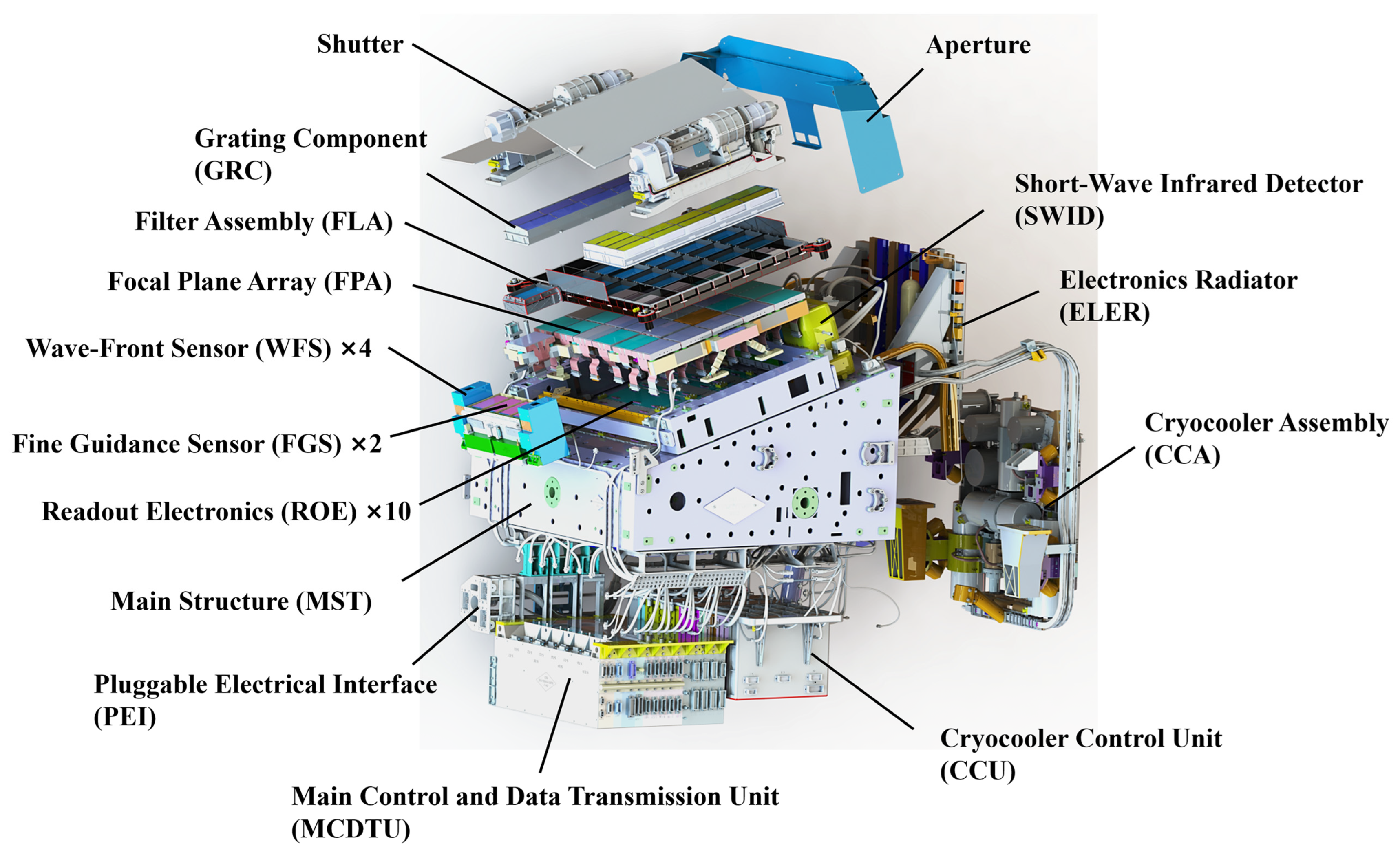
The SC consists of 28 components, all integrated into the MST, as shown in Figure 2. The FPA, with a size of 500 × 600 mm, is in the main imaging area of the survey field of view (1.1° × 1.0°). Within the FPA, 31 CCDs are deployed. The Short-Wave Infrared Detector (SWID) is coplanar with the FPA but independent of it, enabling temperature control under different operating conditions. On both sides of the main imaging area of the survey field of view are the fields of view (0.2° × 1.0° × 2) for the Fine Guidance Sensors (FGS) and Wave-Front Sensors (WFS). Within these fields, two Fine Guidance Sensors (FGS) and four Wave-Front Sensors (WFS) are installed, responsible for observation and positioning, and measuring wavefront distortion of light waves, respectively. The Filter Assembly (FLA) and Grating Component (GRC) are positioned at the front end of the FPA, sequentially achieving selective wavelength transmission and spectral formation. The foremost shutter controls the camera’s exposure. Ten Readout Electronics (ROEs) are placed in the central cavity of the MST, connected to each CCD via flexible cables. Multi-layer insulation materials are installed between the ROEs and the FPA to block heat transfer. The Electronics Radiator (ELER) and Cryocooler Assembly (CCA) are mounted on the side of the camera, jointly realizing temperature control for the entire camera. The ELER stabilizes the operating temperature of each electronics unit at approximately 20 °C through passive heat dissipation. The CCA, equipped with 4 refrigeration compressors, controls the temperatures of the FPA assembly and SWID to below 185 K and 80 K. This assembly is connected to the MST via four liquid-damped vibration isolators to achieve vibration suppression, with the support stiffness after vibration isolation being less than 10 Hz. To ensure the support stiffness during the launch process, the vibration isolators of the CCA remain locked until the SC enters orbit. The Cryocooler Control Unit (CCU) and Main Control and Data Transmission Unit (MCDTU) are located at the lower part of the camera. Both communication and power transmission between the SC and CSST are accomplished through the Pluggable Electrical Interface (PEI).
In the shutter-closed state, the overall dimensions of the survey camera are 895 mm × 1047 mm × 1047 mm, with a launch mass of 450 kg. The fundamental frequency is required to be ≥100 Hz. While meeting the requirements of high load-bearing capacity and high stiffness, the MST must also have sufficient strength, with its mass controlled within 68 kg. Furthermore, it must provide high-precision MRs for components such as the FPA and SWID.
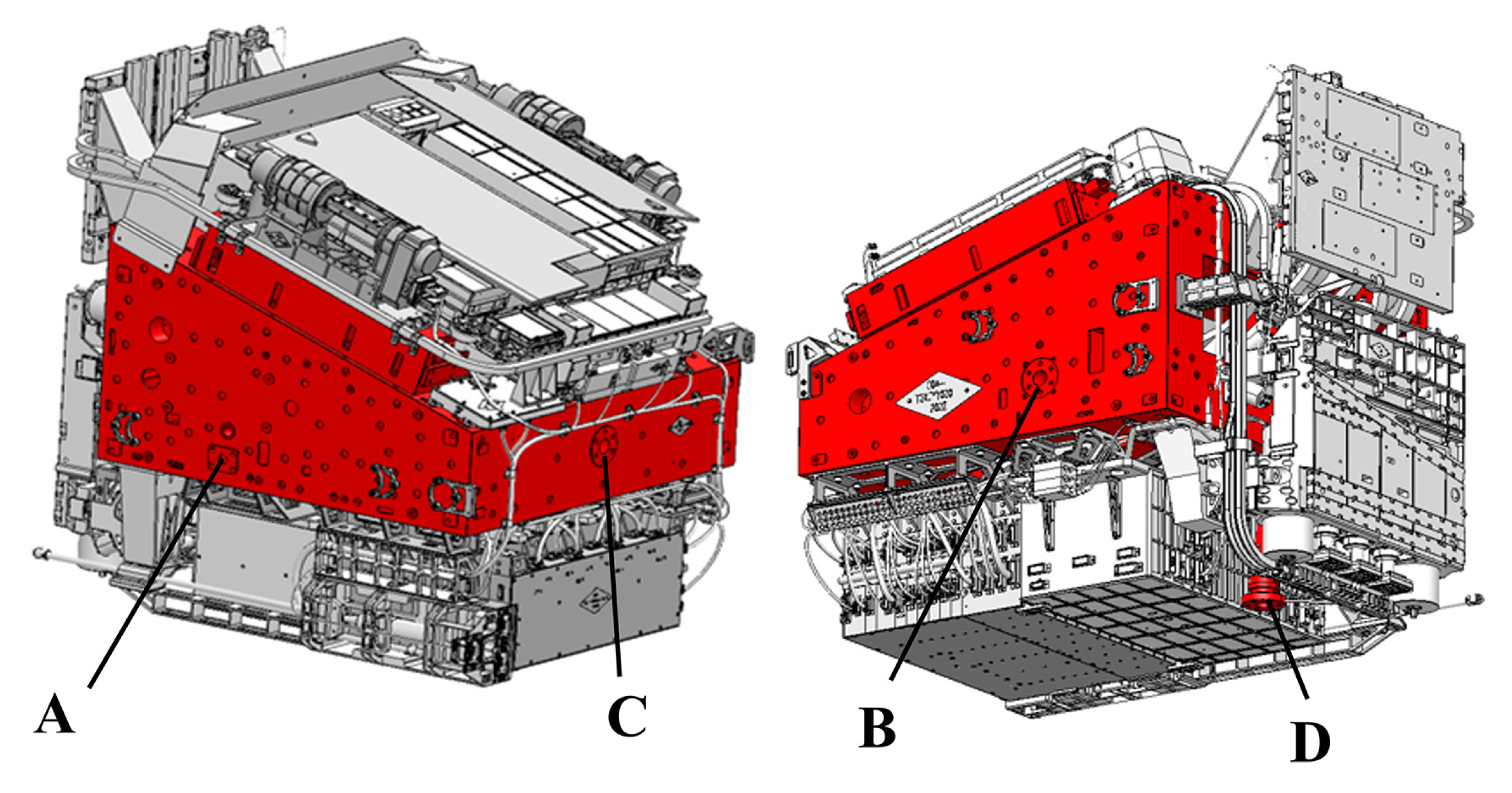
To support future upgrades and enhance system reliability, the SC and some of its components are designed in accordance with the requirements for Orbital Replacement Units (ORUs) [24]. The MST has been optimized in multiple detailed dimensions simultaneously: first, all edges have been rounded to prevent sharp edges from scratching astronauts’ spacesuits; second, a robotic arm adapter interface has been installed on the MST surface near the hatch for connecting the robotic arm and the space telescope camera; third, various markers have been arranged on the MST surface to provide clear identification references for astronauts’ operations. In terms of mechanical interfaces, the SC is docked with the CSST via four mechanical interfaces (A, B, C, and D Mounting Interfaces) on the MST, as shown in Figure 3. Each interface is equipped with automatic/manual unlocking functionality, enabling on-orbit unlocking and separation between the SC and CSST, thereby providing hardware support for its extraction and maintenance operations.

3. MST Design and Optimization

3.1. Configuration and Composition

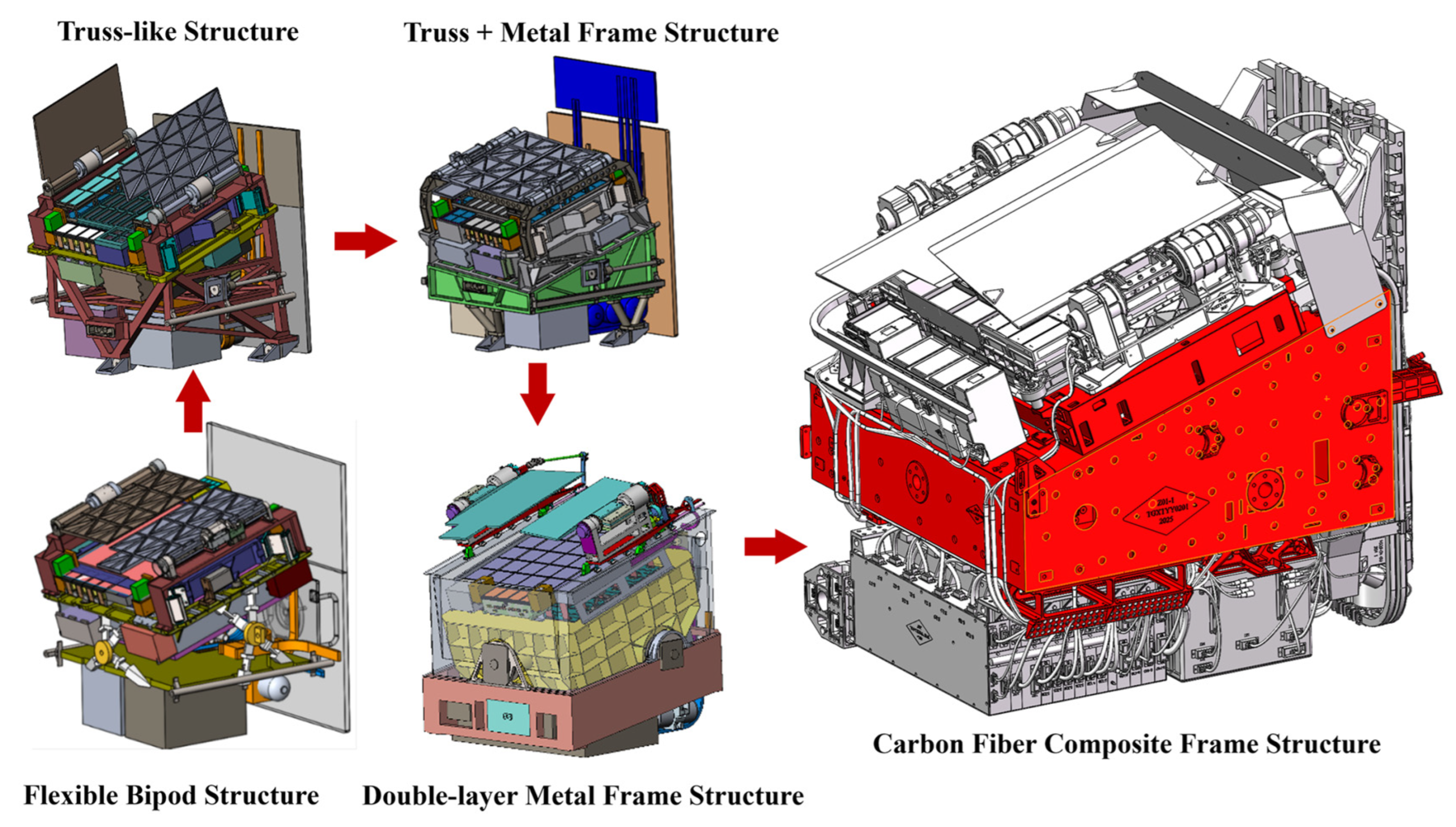
During the design process of the MST configuration, multiple structural concepts—including the flexible bipod structure, truss-like structure, truss + metal frame structure, and double-layer metal frame structure—were systematically evaluated through several rounds of technical iteration. Figure 4 illustrates the iterative evolution of these configurations. After comprehensive multi-dimensional assessments considering mechanical performance, thermal control characteristics, and material compatibility, the carbon fiber composite frame structure was ultimately selected.
In terms of load-bearing capacity, the frame structure provides more mounting interfaces compared to other configurations, effectively enhancing spatial utilization and aligning seamlessly with the SC’s high integration density and numerous load-bearing components. Thermally, the inherently low thermal conductivity of the carbon fiber composite facilitates the establishment of an efficient thermal isolation system, enabling differential temperature control for various camera components. Additionally, its coefficient of thermal expansion (1–2 × 10⁻⁶/°C) closely matches that of the silicon carbide substrate (~2 × 10⁻⁶/°C) of the FPA, reducing thermally induced deformation and ensuring long-term optical stability, which is critical for high-precision imaging devices.
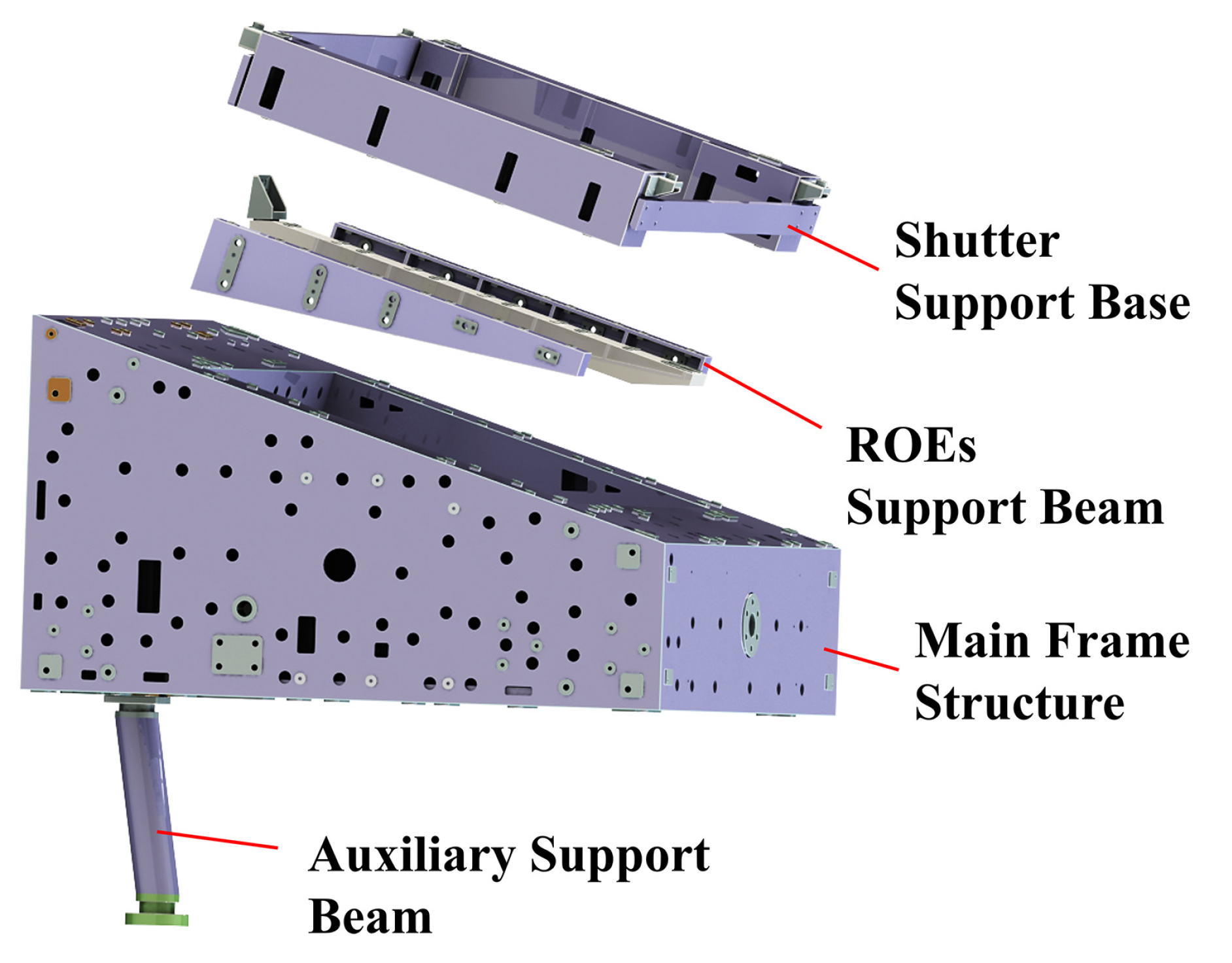
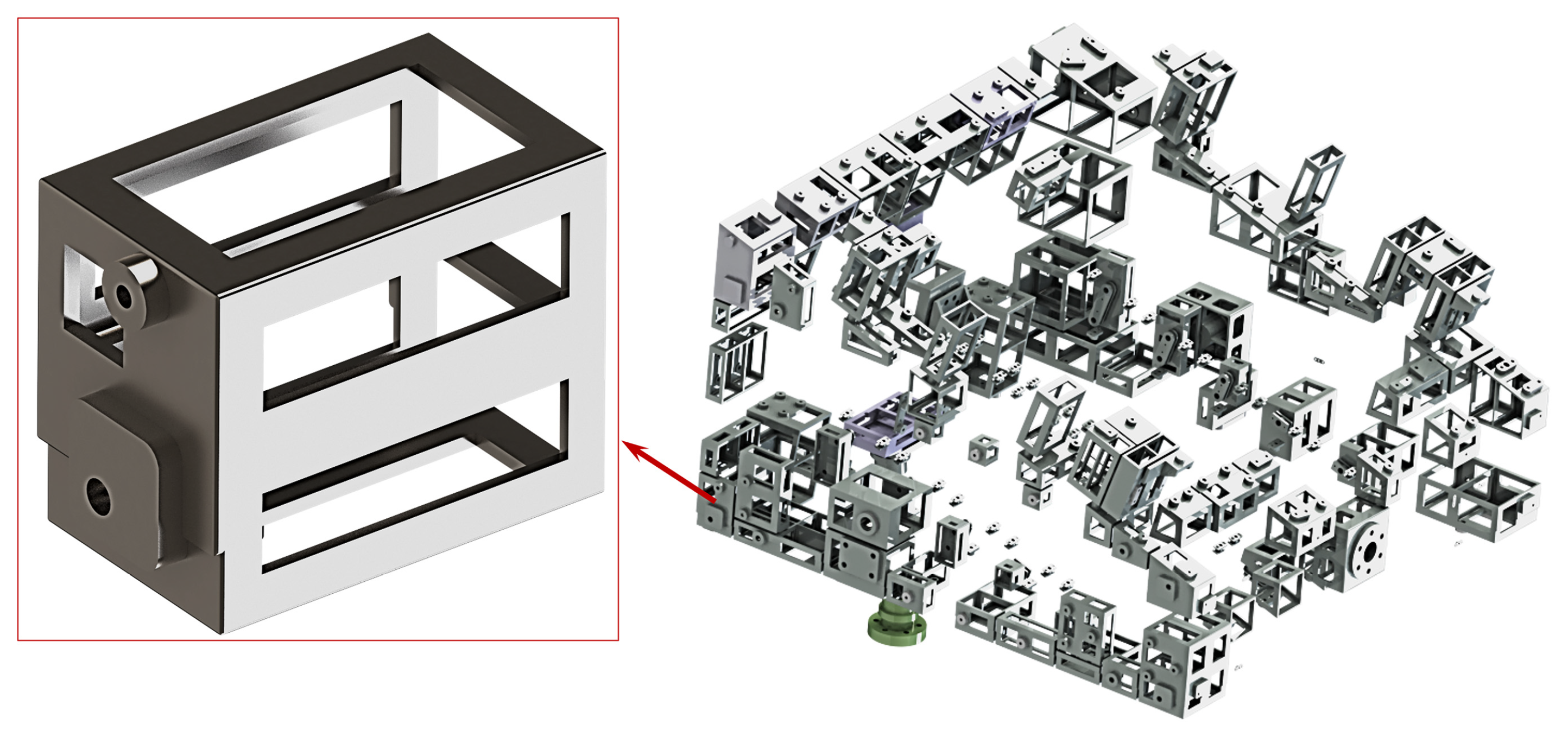
The MST is mainly composed of the main frame structure, shutter support base, ROEs support beam, and auxiliary support beam, as shown in Figure 5. Each component achieves precise positioning and connection with the main frame through locating pins and high-strength screws. The main frame structure, as the primary load—bearing component, is an integrated wedge—shaped frame with a central cavity. This design effectively avoids the problem of connection stiffness loss and enhances the structural stability.

3.2. Carbon Fiber Layup Process and Material Selection

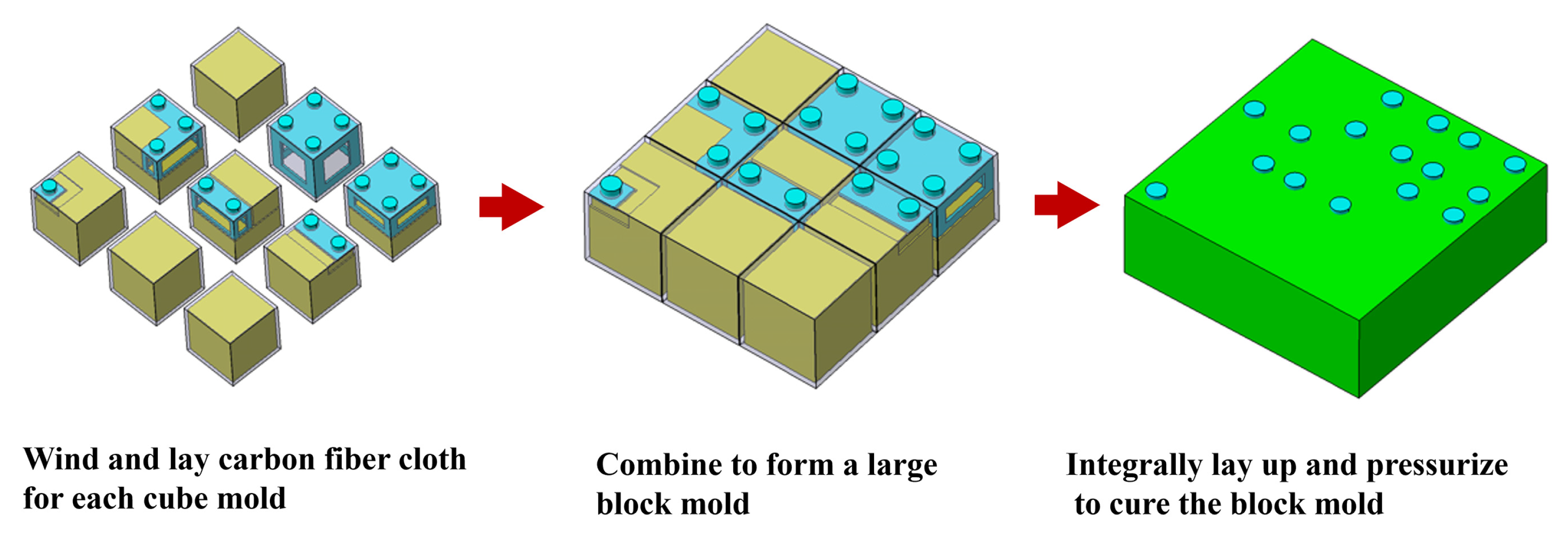
Since carbon fiber composites are not suitable for thread machining, titanium alloy parts are pre-embedded at all interfaces of the MST, and bosses are exposed for thread machining. The MST adopts a carbon fiber layup manufacturing process of “cube mold laying—integral assembly—integral laying”. The specific process is as follows: first, assemble the titanium alloy inserts with soluble core molds into cube molds, then cut carbon fiber unidirectional tapes according to the mold shapes, and wind them onto the surface of each cube mold at the designed angle; subsequently, assemble the wound cube molds to form a block mold; then, integrally lay up the block mold. An outer mold is used to apply pressure to the block mold, and the composite material is fully cross-linked through heating and curing. After curing, drill process holes on the outer surface of each cube mold, and dissolve the soluble-core molds via high-pressure water injection to remove the soluble cores. Clean the residual overflow glue at the mold-splicing joints carefully. Finally, complete the rough machining of the carbon fiber composite component. Figure 6 illustrates the carbon fiber layup process.
The MST adopts M55J carbon fiber as the reinforcing material. This grade falls into the category of high-modulus carbon fibers [25], and it is among the fiber materials with the most superior stiffness performance in the current aerospace field, providing reliable support for achieving the MST’s high stiffness characteristics. To enhance the adaptability and reliability of the MST in the space environment, cyanate ester resin is selected as the matrix material. Compared with epoxy resin, cyanate ester resin has an extremely low moisture absorption rate, a higher initial thermal weight loss temperature, excellent dimensional stability, superior heat resistance, good mechanical properties, excellent dielectric properties, and favorable processability and molding performance [26,27,28,29,30,31]. In terms of processing, copolymerization modification technology is used to regulate the viscosity of cyanate ester resin, enabling the resin to remain in a liquid state under hot-melt prepreg processing conditions, thereby preparing unidirectional tape prepregs. The thickness of the unidirectional tape is controlled at 0.1 mm, and the fiber volume content is 60 ± 1.5%. Cyanate ester resin is cured via addition polymerization, during which no volatile substances or by-products are generated, resulting in a significantly lower content of small molecules in the cured product compared with traditional epoxy resin. In addition, during the modification process for processability and comprehensive performance, the selected modifiers are all polymers or inorganic materials, and the modification methods employ chemical cross-linking, which minimizes the impact of modification on the vacuum outgassing performance of cyanate ester resin. The vacuum outgassing performance of the modified M55J carbon fiber/cyanate ester resin composite is detailed in Table 1. Before the MST undergoes precision machining procedures, a 96 h vacuum degassing treatment will be conducted. During this process, the temperature is controlled at 40 °C, and the vacuum degree is maintained at a level better than 1 × 10⁻³ Pa, which can effectively remove volatile impurities in the material, thereby reducing the risk of contamination to the camera.
Over 200 titanium alloy parts are embedded in the carbon fiber composite cavity of the MST and undergo synchronous curing with the composite material. Considering the difference in linear expansion coefficients between titanium alloy and carbon fiber composite, to avoid peeling during curing and subsequent service, the size of each embedded part is strictly controlled within 100 mm. To enhance the bonding strength between the embedded parts and the composite, the outer surfaces of the embedded parts are sandblasted. This increases surface roughness, effectively expanding the bonding contact area. In addition, each embedded part is provided with a boss structure, which is exposed on the surface of the composite material after molding for subsequent thread machining. Sufficient allowance is reserved for the boss height, and finish machining will be performed on the boss after the carbon fiber structure is molded to ensure interfacial precision. All embedded parts are designed with lightweight considerations, as shown in Figure 7, and the wall thickness of all embedded part structures is controlled at approximately 3 mm.

3.3. Optimal Design and Performance Analysis

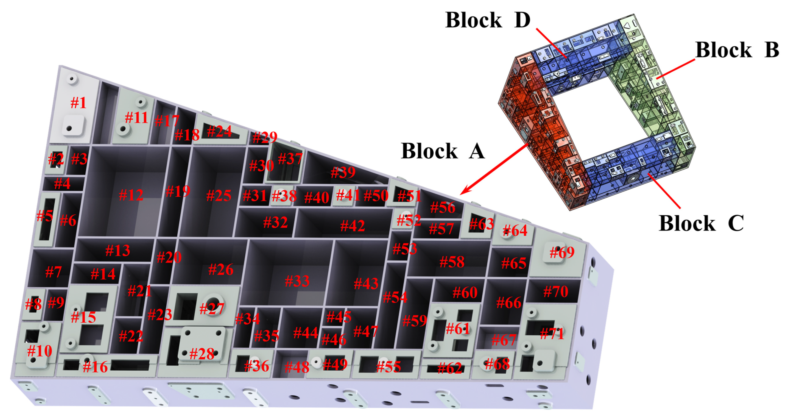
To minimize the mass of the MST while meeting stiffness requirements and maximize structural efficiency, size optimization techniques [32] were applied to optimize the carbon fiber ply thickness of each cube mold. The essence of size optimization lies in the coupling of finite element analysis and optimization algorithms. By parameterizing the carbon fiber layup thickness of each cube mold, the minimum weight is achieved under the constraint of overall fundamental frequency. Its principle can be summarized as follows: with size parameters as variables, finite element calculation methods as performance evaluation tools, and optimization algorithms as search engines, the design is updated through iterative calculations until convergence. Taking the Main Frame Structure of the MST as an example, it can be divided into four blocks (A, B, C, and D), each consisting of several cube molds. A partial cross-sectional view of Block A is shown in Figure 8. The thickness of the crisscross internal stiffeners is the sum of the carbon fiber layup thicknesses of adjacent small block molds.
The MST adopts an in-plane isotropic layup to ensure structural dimensional stability and a uniform linear expansion coefficient. Each layup group has a layup angle sequence of 0°/90°/45°/−45°/−45°/45°/90°/0° with a thickness of 0.8 mm. The layup thickness of cube molds is set as an integer multiple of the layup group thickness, which can significantly reduce the degrees of freedom in size optimization and facilitate convergence. Meanwhile, the layup thickness is limited to the range of 1.6–8 mm to avoid degradation of structural mechanical performance caused by stress concentration due to excessive thickness differences.
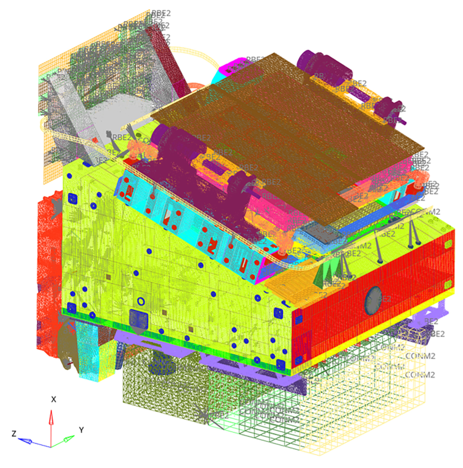
The finite element model of the SC is shown in Figure 9. A hybrid modeling method with multiple element types (including solid, shell, beam, and mass point elements) was adopted to construct a model containing over 1 million elements. The carbon fiber ply thicknesses of each cube mold and outer skin were parameterized, with layup rules and thickness limits (1.6–8 mm) set simultaneously. Taking the constraint that the overall fundamental frequency of the camera should not be less than 125 Hz (overall modes and local modes are distinguished based on the criterion that the modal effective mass ratio is ≥10%), and aiming at minimizing the weight of the MST, the ply thicknesses of each cube mold were optimized.
The thickness distribution of carbon fiber plies in various parts of the optimized MST is shown in Table 2. The carbon fiber ply thicknesses in different functional regions range from 1.6 mm to 5.6 mm, with a total mass of only 66.8 kg, including 28.2 kg of titanium alloy inserts and 38.6 kg of carbon fiber composites.
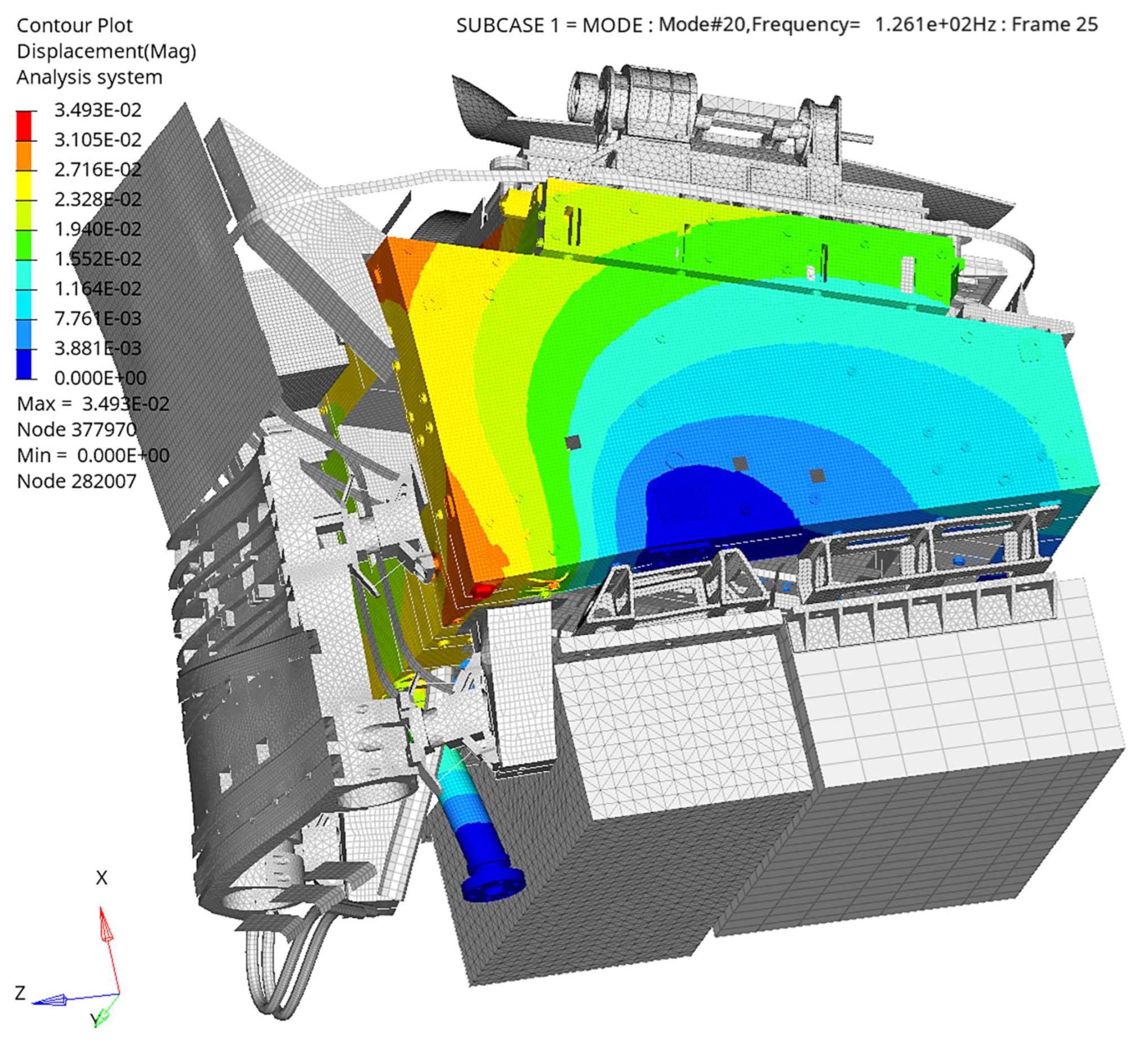
The overall fundamental frequency of the SC reaches 126.1 Hz (under the constraint of ABCD mounting interfaces), and its mode shape is shown in Figure 10. The designed stiffness meets the requirement of ≥100 Hz with a certain margin. While satisfying the structural stiffness, the lightweight design goal has been achieved.
The structural strength of the MST is also a core consideration. The sine vibration frequency of the SC ranges from 5 to 100 Hz with a maximum acceleration of 6 g, while the random vibration frequency spans 20–2000 Hz with a maximum power spectral density of 0.02 g2/Hz and a total root mean square acceleration of 4.02 gRMS. Since the overall fundamental frequency of the camera exceeds 100 Hz, resonance of the MST will not be excited within the sine vibration frequency band. Therefore, the primary threat to the structural strength arises from random vibrations.
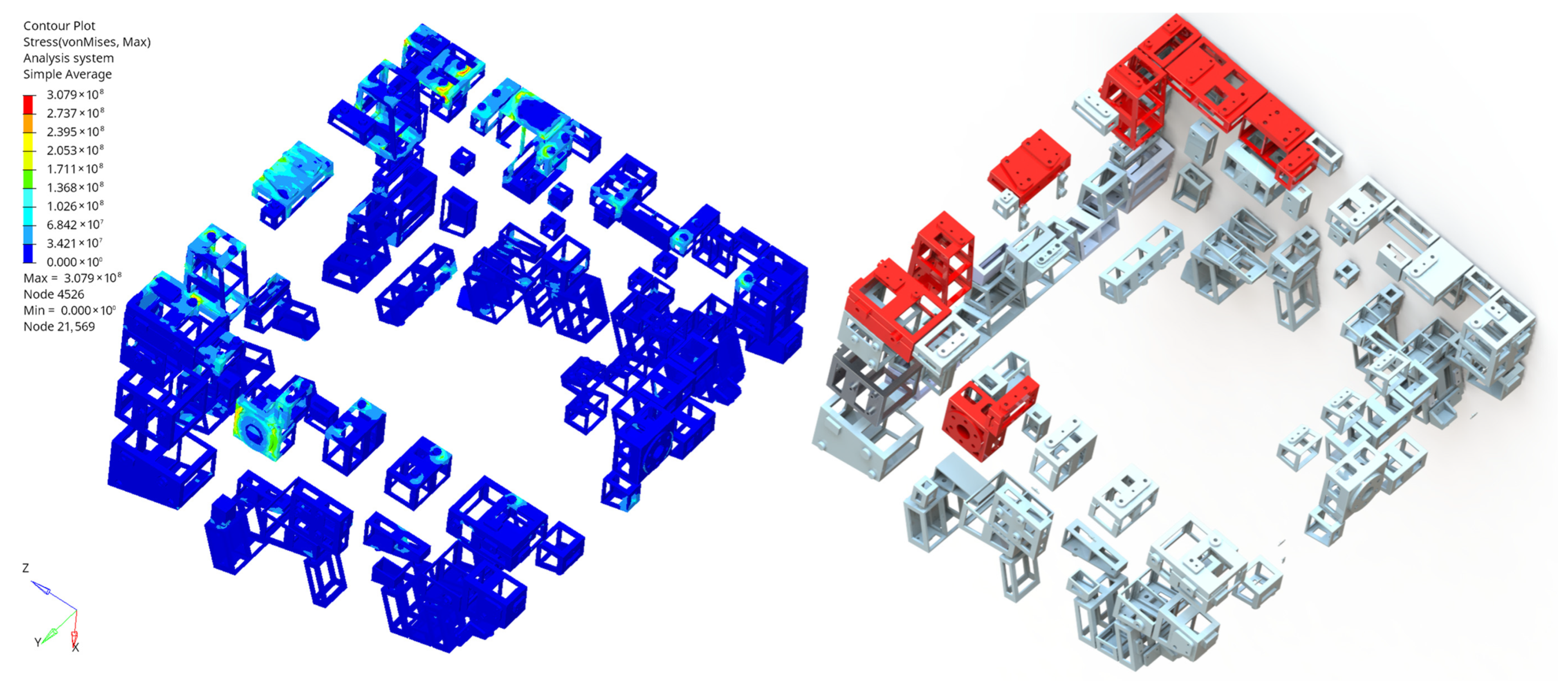
Under random vibration in the X-direction, the longitudinal stress of the composite material in the MST reaches its maximum value of 253.8 MPa (3σ), as shown in the cloud diagram in Figure 11 (left). Although this stress remains within the allowable range of the material, local reinforcement of the carbon fiber plies in the MST was still carried out based on the force transmission paths revealed by the cloud diagram, as shown in the red area of Figure 11 (right). After optimization, the stress was reduced to 140.5 MPa, demonstrating a significant improvement.
The stress of the embedded parts reaches its maximum value of 307.9 MPa (3σ), as shown in the cloud diagram in Figure 12 (left). For the embedded parts with relatively high stress, measures such as increasing the thickness of the frame, reducing the size of the weight-reduction holes, and optimizing the filet radius were adopted, as indicated in the red-marked areas in Figure 12 (right). After these modifications, the maximum stress was reduced to 265.3 MPa, thereby further improving the structural strength and mechanical reliability.
The strength performance analysis results of the optimized MST under sine and random vibration conditions are presented in Table 3. For key mechanical indicators, such as the longitudinal stress, transverse stress, and shear stress of the carbon fiber plies, as well as the von Mises stress of the titanium alloy inserts, under the evaluation system with a safety factor of 1.35, the minimum safety margins of the composite materials and the titanium alloy inserts can reach 1.64 and 1.23, respectively. Thus, the structure has sufficient safety margins, and its structural strength and reliability are adequately guaranteed.

4. Manufacturing and Testing of the MST

4.1. Manufacturing and Machining

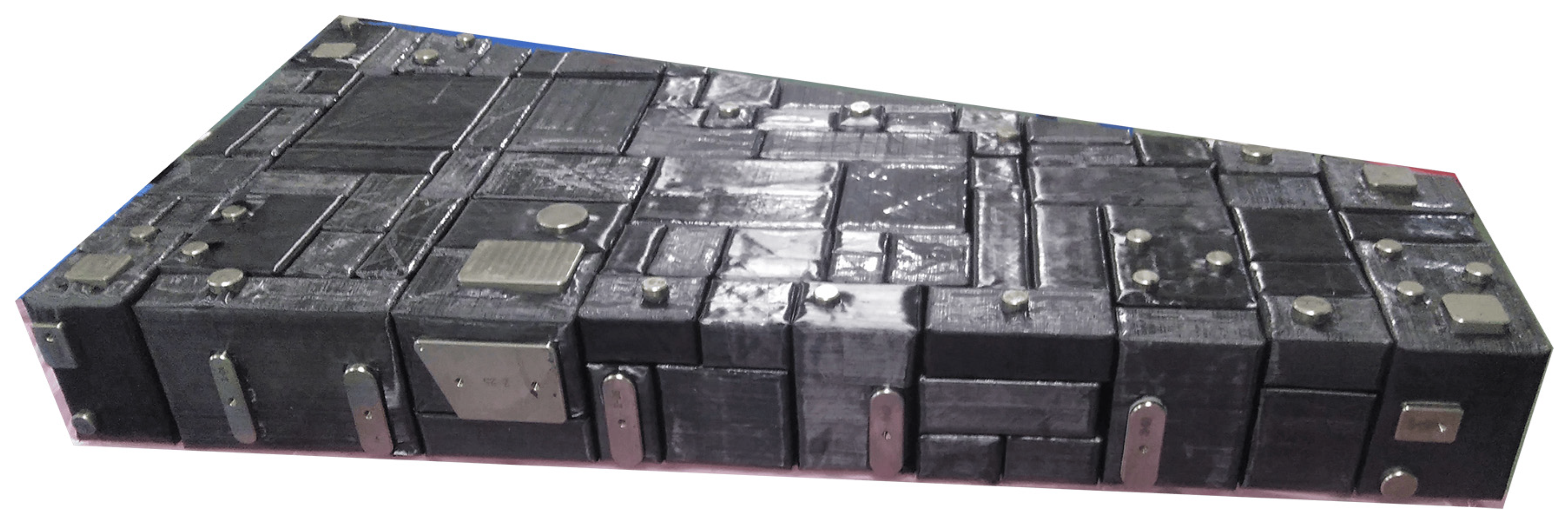
Block A of the MST before curing is shown in Figure 13. Considering that mold-closing errors in the manufacturing process will lead to deviations between the actual positions of the embedded parts and the design values, the boss surfaces of the embedded parts must have sufficient dimensions to ensure that the precision-machined threaded holes can be accurately machined on the corresponding bosses. The specific requirements are as follows: the diameter of the boss surface for threaded holes of M5 and smaller specifications should not be less than Φ15 mm, and that for M6 and M8 threaded holes should not be less than Φ20 mm.
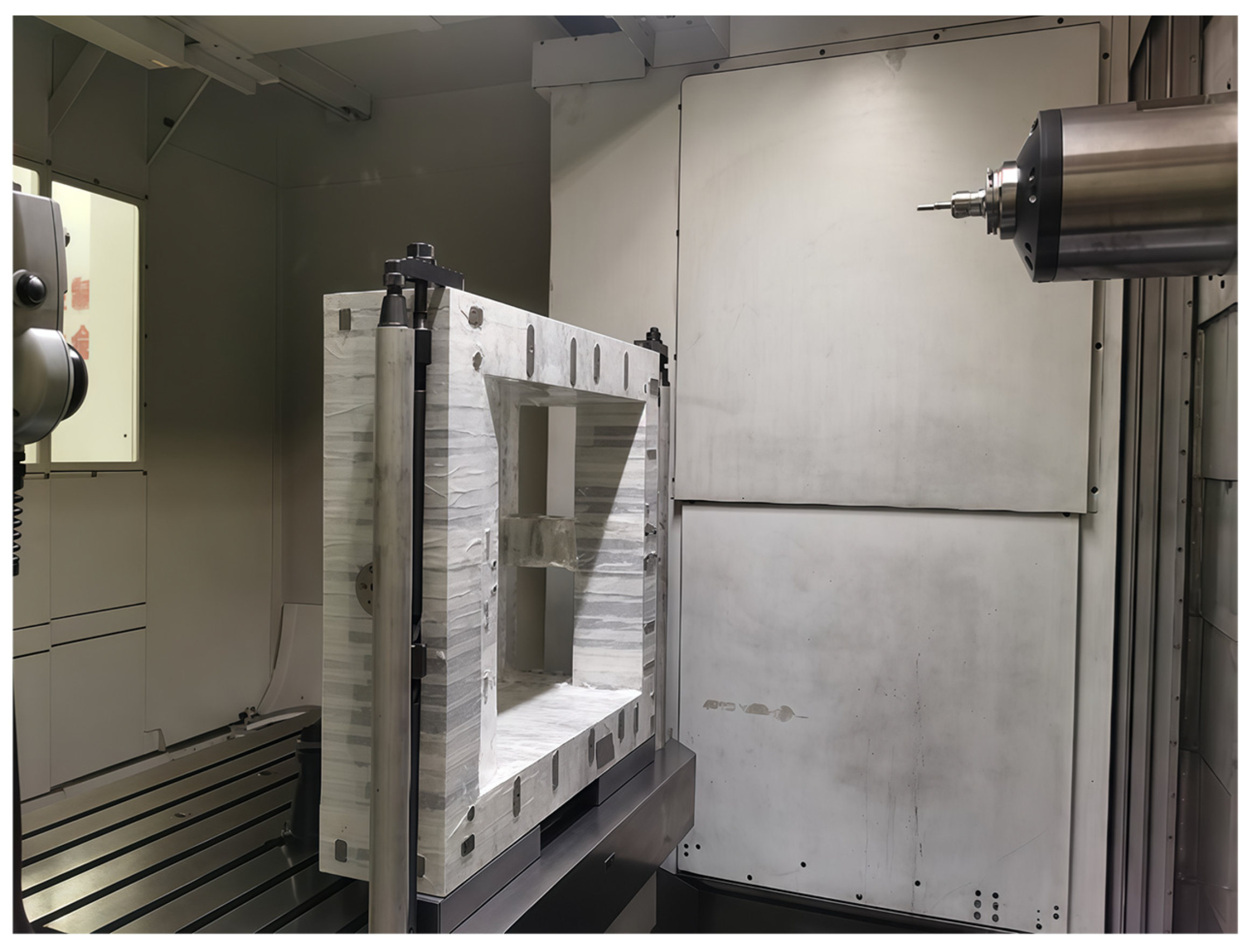
In the precision machining stage of the MST, key processes such as precision milling and grinding of each structural surface, as well as drilling and tapping of each interface, must be completed. Since carbon fiber composites are sensitive to cutting fluids, being prone to contamination and corrosion, and metal chips generated during machining may fall into the process holes of the MST—potentially forming excess materials and posing quality hazards—special tape is used to cover and protect the MST, leaving only the titanium alloy inserts’ bosses to be machined exposed, as shown in Figure 14. After precision machining, the roughness of each mounting surface of the MST is held within 1.6 μm, and the flatness is held within 0.01 mm; the parallelism and perpendicularity between mounting surfaces are both held within 0.02 mm, and the positional tolerance of each mounting hole is held within 0.1 mm.

4.2. Free Modal Testing

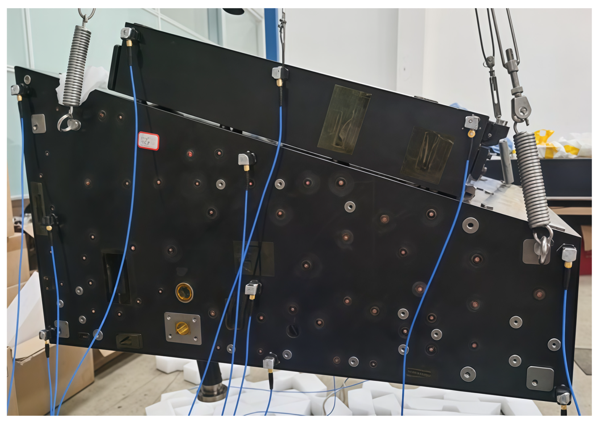
To investigate the dynamic characteristics of the MST under free boundary conditions and verify the previously established finite element model as well as the effectiveness of stiffness optimization, a free modal test on the MST was conducted. In the test, the lifting rings at the four corners of MST were connected via a combination of steel wires and springs in series to suspend the structure, with the suspension configuration as shown in Figure 15. The frequency of the suspension system was less than 3.9 Hz, which is far lower than 5% of the fundamental frequency of the main structure, thus satisfying the approximate requirements for the free boundary condition test.
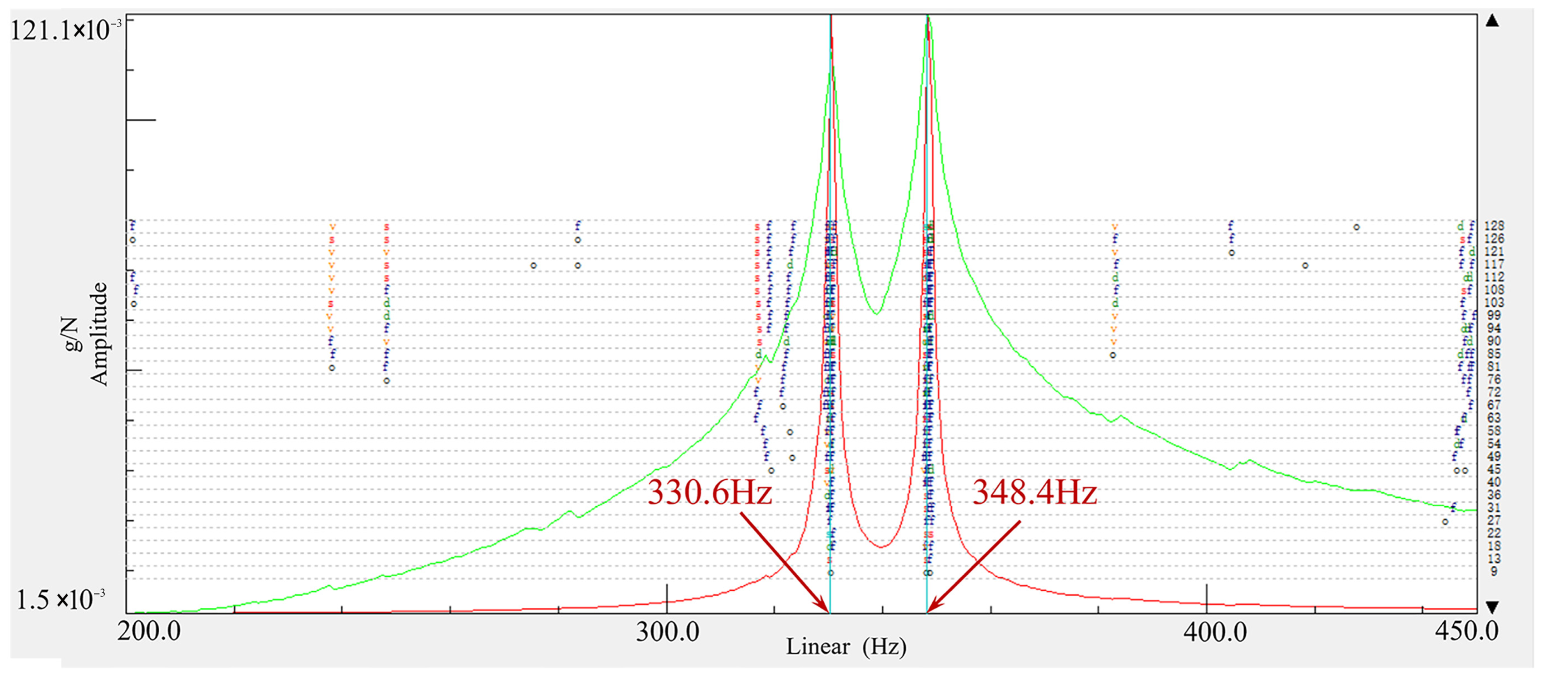
The designated characteristic positions of the MST were tapped with an impact hammer, and the response signals from each acceleration sensor on the structure were collected. The modal parameters of the MST were extracted using the PolyMAX modal identification algorithm [33] in Siemens Testlab® (TL-DTP.21.1) software. Figure 16 shows the frequency response curves of the MST in the 200–450 Hz frequency range, with the fundamental frequency under free boundary conditions being 330.6 Hz.
A comparison between the measured and simulated results of the modal frequencies and mode shapes of the MST under free boundary conditions is presented in Table 4. The maximum frequency deviation between the simulation and measurement is only 7.8%, and the mode shapes of each order are consistent, which verifies the validity of the finite element model of the MST and the reliability of the 126.1 Hz full-load overall fundamental frequency analyzed based on this model.
Under free boundary conditions, the first five orders of modal shapes of the MST are shown in Figure 17, namely the 1st torsional mode, 2nd torsional mode, 1st radial mode, 2nd radial mode, and bending mode in sequence.

4.3. Integration and Calibration of the MRs

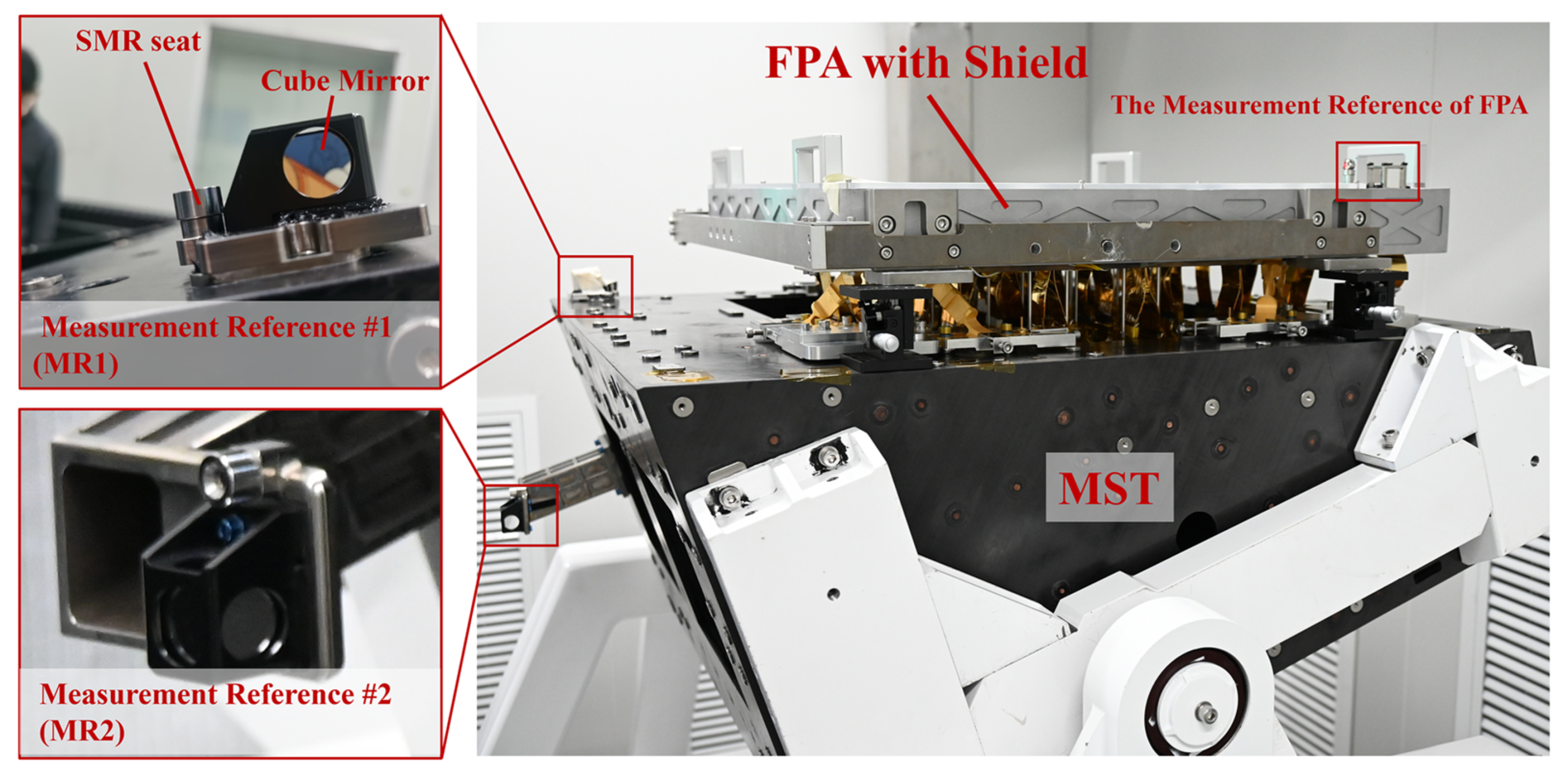
To ensure the precision of the installation positions of each component in the SC, MRs must be established on the MST. These MRs can also enable the precise expression of the camera’s position during the integration of the SC with the CSST. Unlike the multi-SMRs (spherically mounted retroreflectors) calibration schemes adopted by Euclid [34] and JWST [35], the MST employs a composite MR system consisting of an SMR (representing spatial position) and a cube mirror (representing spatial angle). Compared with the multi-SMR calibration scheme, the composite system only requires exposing the MR at a single position, resulting in looser line-of-sight constraints and better satisfying the measurement requirements of the SC at all stages. Additionally, the introduction of the cube mirror ensures that angular measurement accuracy is not limited by the component span, thereby enhancing the accuracy and stability of angular measurements. The MRs settings for the MST and FPA are presented in Figure 18. Two independent MRs (MR1 and MR2) were deployed on the MST. This design not only expands the degrees of freedom in measurement but also further improves the reliability and accuracy of measurements through the dual-reference mutual verification mechanism.
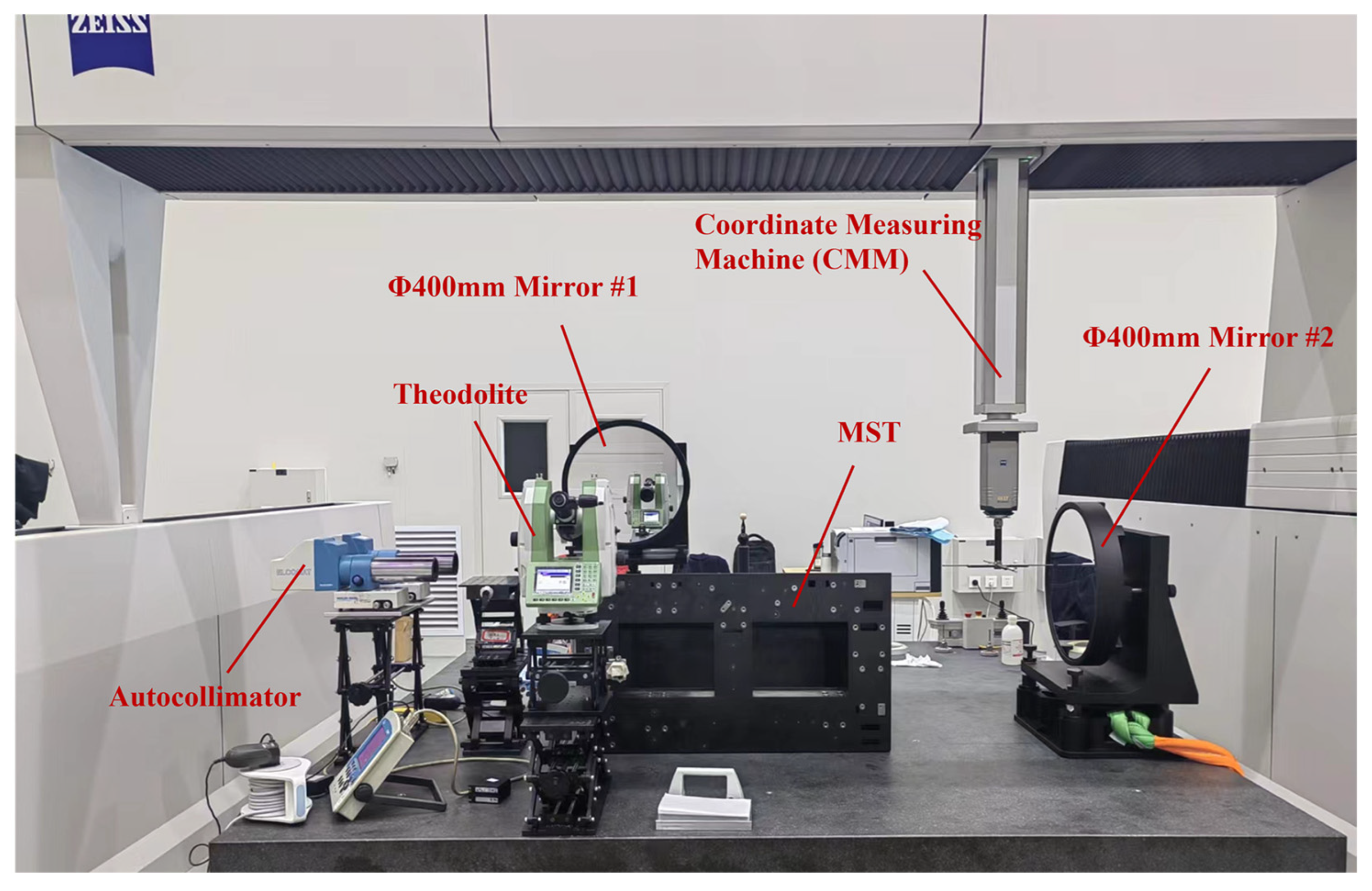
To transfer the mechanical geometric datum of the MST to the MRs (MR1 and MR2), a hybrid contact–noncontact calibration scheme was adopted. Specifically, a coordinate measuring machine (CMM) measured the characteristic surfaces and holes of the MST, thereby establishing the mechanical geometric datum. Then, the CMM measured the angles of the two Φ400 mm mirrors relative to the geometric datum. Furthermore, an autocollimator and a theodolite measured the angles between the two Φ400 mm mirrors and the corresponding surfaces of the cube mirrors in the MRs. From these two sets of measurement data, the angular relationship between the mechanical geometric datum and the MRs could be derived. Finally, the CMM measured the center positions of the SMRs, thus allowing the six-dimensional spatial relationship between the mechanical geometric datum and the MRs to be determined. The position and angle measurement uncertainties of this scheme are 5.26 μm/5.53″ (3σ), respectively, and the calibration scenario is presented in Figure 19.

4.4. Vibration Test

To verify the strength of the MST, a qualification-level vibration test (as shown in Table 5) was conducted on it using counterweights. After counterweight adjustment, the inertia of the entire system remained consistent with that of the SC. The test scenario is shown in Figure 20.
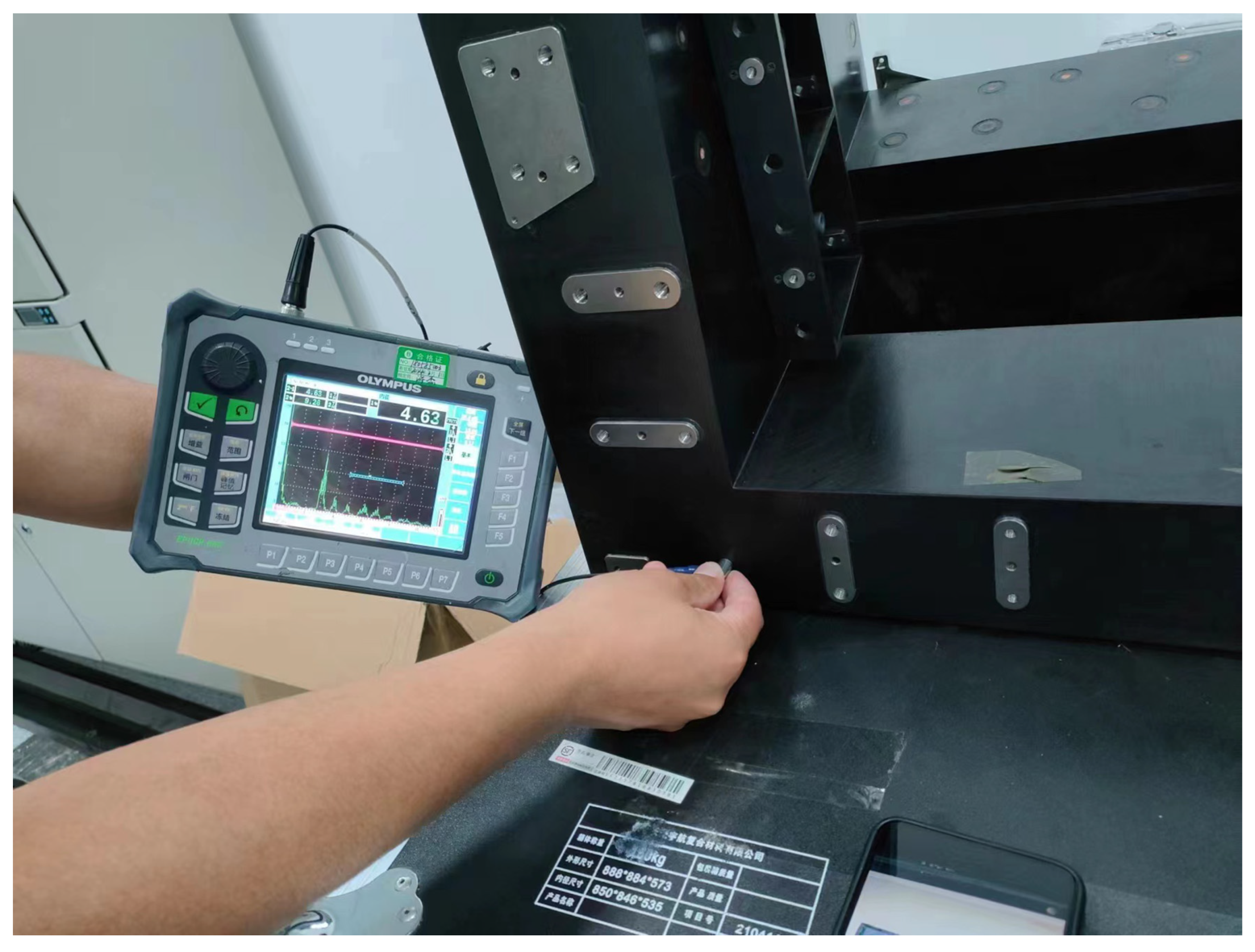
After the vibration test, ultrasonic flaw detection was conducted on the MST, as shown in Figure 21. The results indicated that no defects such as fiber breakage, delamination, or misalignment were observed in the composite material, and no debonding occurred at the interface between the composite and the embedded parts. Additionally, the CMM inspected the geometric characteristics of the MST. The results showed that there were no significant changes in the form and position accuracy of the mounting surfaces and interfaces. The strength and stiffness of the MST are sufficient to withstand the launch environment.

5. Testing and Experimentation of the SC

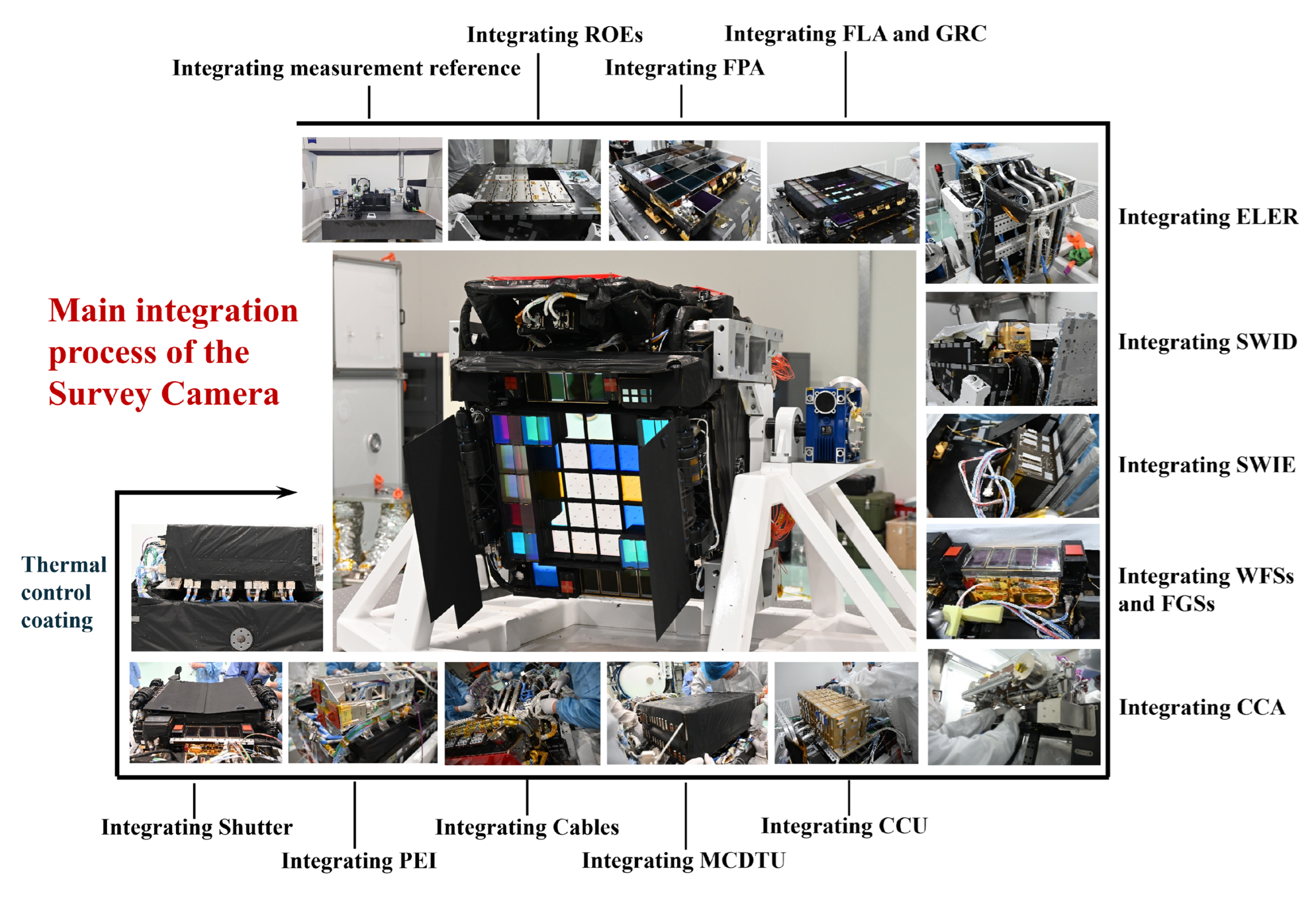
Through testing and experimental verification, all functional and performance requirements of the MST were satisfied. It was delivered to the SC in November 2023 and immediately incorporated into the integration and assembly of the SC. Figure 22 illustrates the main integration process. As of June 2024, the integration task has been fully completed, and all mounting interfaces of the MST have been fully validated. By utilizing the two MRs of the MST, the FPA and SWID successfully achieved high-precision integration.
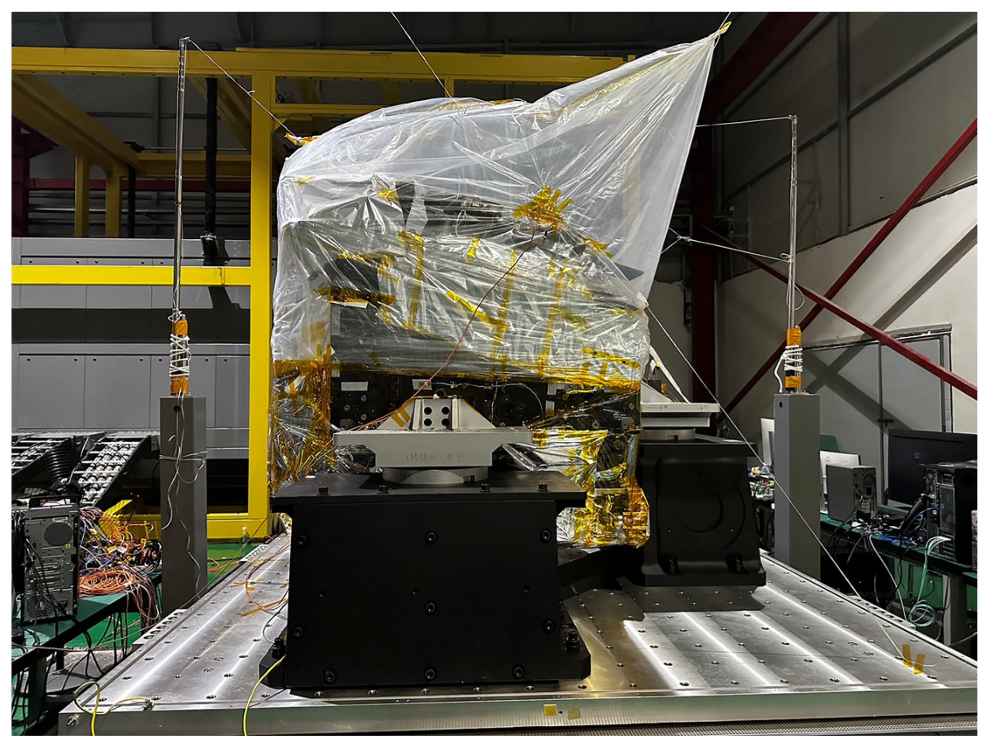
The MST underwent the qualification-level vibration test again along with the SC. To prevent contamination of the camera during the test, comprehensive protective measures were implemented using a film, as shown in Figure 23. Additionally, the overall fundamental frequency of the SC was measured to be 120.6 Hz, confirming that the stiffness of the MST met the requirements.
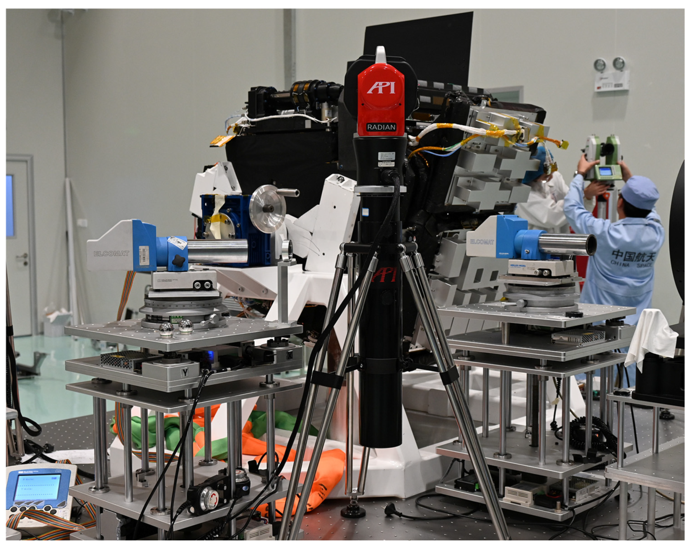
After the vibration test, the angle and position of FPA-MR relative to MST-MR were re-measured, with the specific measurement scenario shown in Figure 24.
The measurement results are presented in Table 6. Before and after the vibration test, the maximum variations in the angle and position of FPA-MR relative to MST-MR were 5.4″/22 μm, respectively. These variations mainly stemmed from factors such as deformation of the MST, deformation of the flexible bipod between the FPA and MST, and measurement repeatability errors. The above variations were within the expected controllable range, and the FPA position after the vibration test still satisfied the accuracy requirements, thus validating the mechanical stability of the MST.
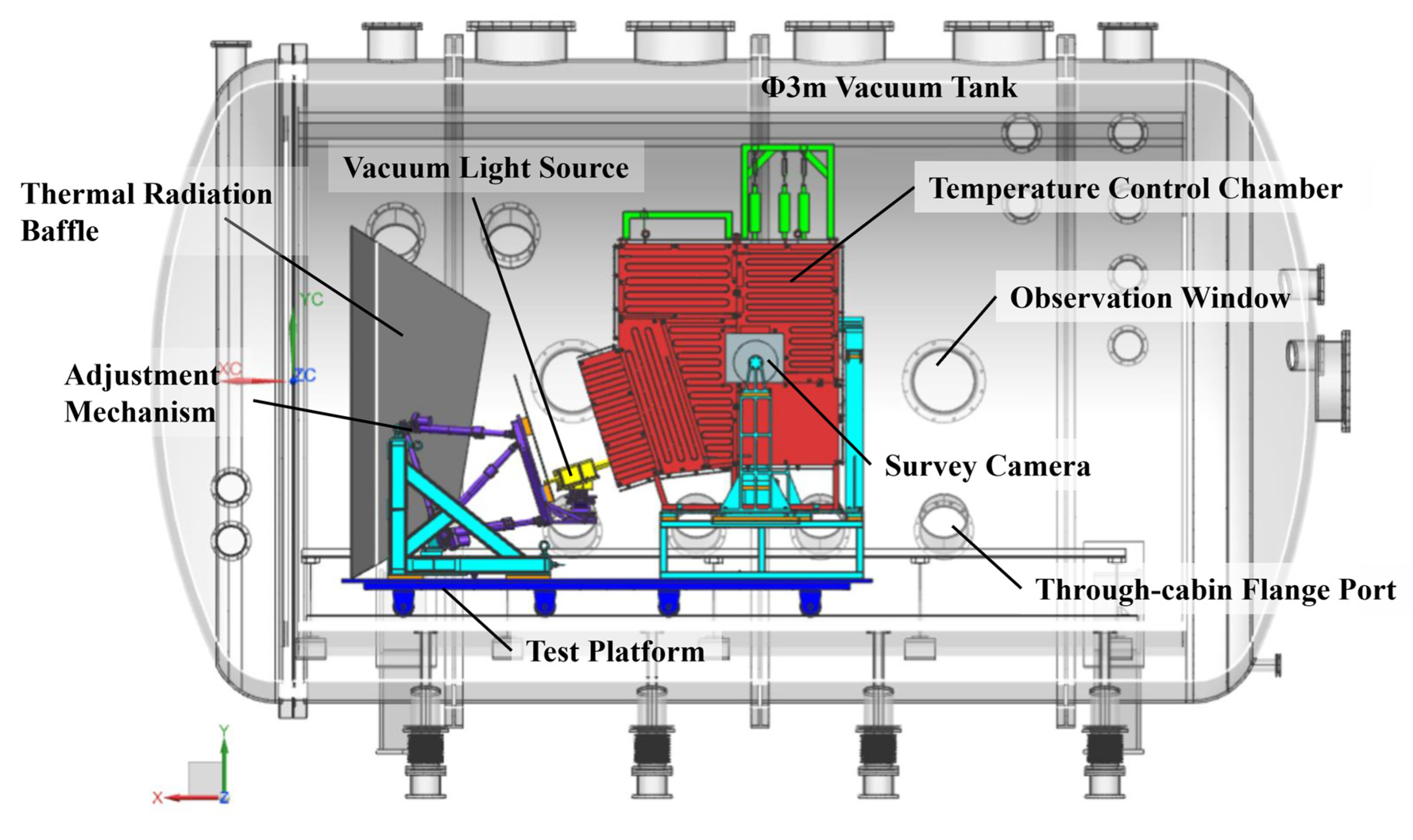
To verify the operating performance of the SC under specified pressure and qualification-level temperature conditions, a thermovacuum test was additionally conducted on the SC, and the composition of the test system is shown in Figure 25. The entire test system was constructed inside a 3 m-diameter vacuum tank. The on-orbit ambient temperature of the SC was simulated using a temperature control chamber and a thermal radiation baffle. The test system was equipped with 80 heating circuits and 164 temperature measurement points, and the minimum and maximum boundary temperatures for the test were −45 °C and 5 °C, respectively.
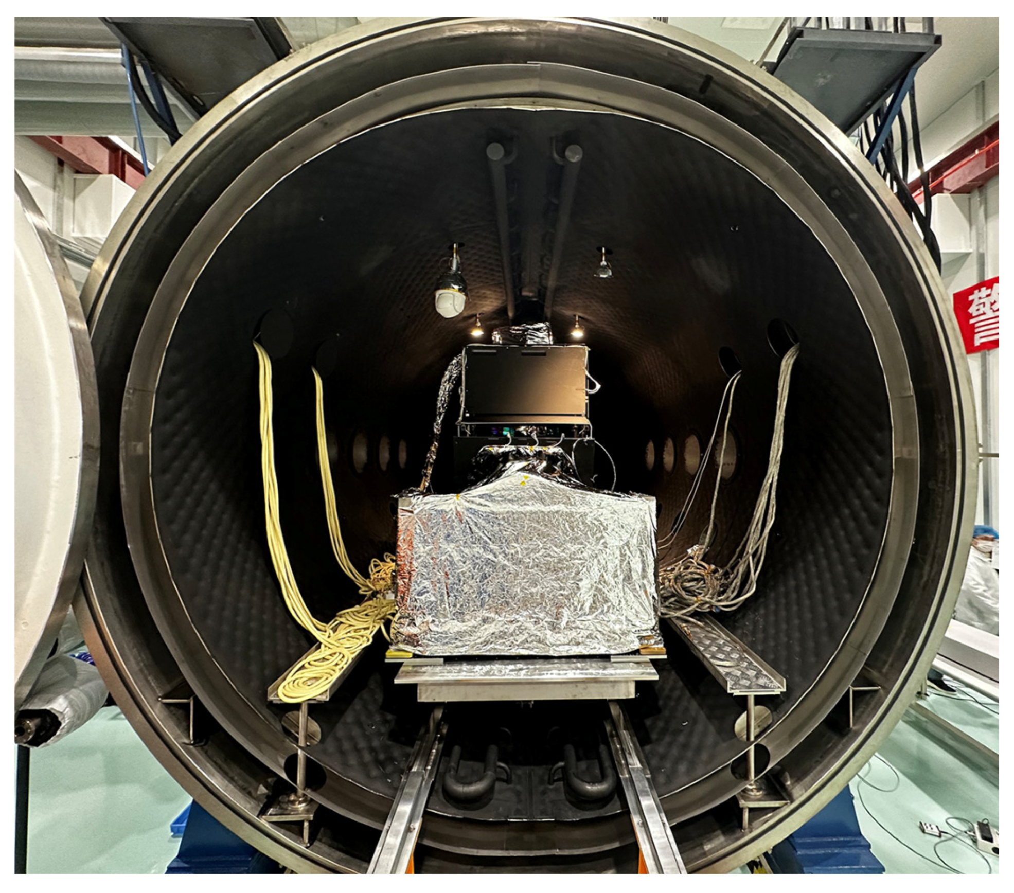
Under the extreme thermal boundary conditions of the thermovacuum test, all components of the SC operated stably. This test verified the camera’s reliability and temperature adaptability in extreme thermal environments. Separate imaging tests were conducted under both high-temperature and low-temperature conditions, and no significant changes were observed in the imaging results—this verified the thermal stability and dimensional stability of the MST. Relevant test scenarios are shown in Figure 26.

6. Conclusions

This study addresses the challenges of lightweight, high stiffness, high strength, and mechanical stability for the Main Structure (MST) of the Survey Camera (SC) aboard the China Space Station Telescope (CSST). A systematic framework integrating structural design, material selection, performance optimization, and multi-condition verification was established. An M55J carbon fiber/cyanate ester composite framework with titanium alloy inserts was adopted, and the carbon fiber ply thickness was optimized to meet the requirements for weight, stiffness, and strength. Additionally, a hybrid SMR–cube mirror measurement reference system was employed to ensure high-precision integration of components. Vibration and thermovacuum tests confirmed the robustness and stability of the MST. This work provides a paradigm for the development of large-scale, highly integrated load-bearing structures for space optical instruments.

Author Contributions

Conceptualization, R.J., A.Z. and W.L.; methodology, R.J., H.Z. and W.L.; software, H.S. and M.H.; validation, R.J., Y.Z. (Yongchao Zhang), S.L., Z.L., S.G., Q.L., H.W., L.W. and Y.M.; formal analysis, R.J.; investigation, R.J.; resources, E.L.; data curation, R.J.; writing—original draft preparation, R.J.; writing—review and editing, A.Z. and W.L.; visualization, J.S.; supervision, A.Z. and J.D.; project administration, W.X., Y.Z. (Yanqing Zhang) and P.C.; funding acquisition, A.Z. All authors have read and agreed to the published version of the manuscript.

Funding

This work was supported by the Manned Space Engineering Project of China.

Data Availability Statement

Data may be available from the corresponding author upon reasonable request and with appropriate approvals.

Acknowledgments

We gratefully acknowledge the support from all institutions and individuals contributing to this work. Special thanks to Changchun Aerospace Composite Materials Co., Ltd. for its expertise in carbon fiber composite manufacturing and titanium alloy insert processing, which ensured MST’s high-precision fabrication. We also extend special gratitude to the China Manned Space Agency (CMSA) for its overall leadership and support in the CSST mission, which laid the foundational guarantee for the SC’s development and integration.

Conflicts of Interest

Author Hongyu Wang was employed by the company Changchun Aerospace Composite Materials Co., Ltd. The remaining authors declare that the research was conducted in the absence of any commercial or financial relationships that could be construed as a potential conflict of interest.

References

  1. Edeson, R.; Aglietti, G.S.; Tatnall, A.R.L. Conventional Stable Structures for Space Optics: The State of the Art. Acta Astronaut. 2010, 66, 13–32. [Google Scholar] [CrossRef]
  2. Liu, X.; Gu, K.; Li, M.; Cheng, Z. Optimization Design of Large-Aperture Primary Mirror for a Space Remote Camera. Sensors 2023, 23, 5441. [Google Scholar] [CrossRef]
  3. Peng, J.; Liu, S.; Wang, D.; Xu, A.; Huang, X.; Ma, T.; Wang, J.; Li, H. Design and Optimization of Thin-Walled Main Support Structure for Space Camera Based on Additive Manufacturing. Micromachines 2024, 15, 211. [Google Scholar] [CrossRef]
  4. Men, S.; Shen, J.; Shi, Y.; Liang, Z.; Li, Z. Optimization Design and Analysis for Support Structure of Space Camera. In Proceedings of the International Conference on Precision Instruments and Optical Engineering (PIOE 2023), Shanghai, China, 25–27 August 2023; Tao, W., Pan, H., Yao, B., Eds.; SPIE: Ile-de-France, France; p. 48. [Google Scholar]
  5. Kang, S.-Y.; Jo, M.-S.; Choi, J.-Y.; Yang, S.S. Cost Effectiveness of Reusable Launch Vehicles Depending on the Payload Capacity. Aerospace 2025, 12, 364. [Google Scholar] [CrossRef]
  6. Sairajan, K.K.; Aglietti, G.S.; Mani, K.M. A Review of Multifunctional Structure Technology for Aerospace Applications. Acta Astronaut. 2016, 120, 30–42. [Google Scholar] [CrossRef]
  7. Wei, L.; Zhang, L.; Gong, X.; Ma, D. Design and Optimization for Main Support Structure of a Large-Area off-Axis Three-Mirror Space Camera. Appl. Opt. 2017, 56, 1094. [Google Scholar] [CrossRef]
  8. Zhang, C.; Li, Z. A Review of Lightweight Design for Space Mirror Core Structure: Tradition and Future. Machines 2022, 10, 1066. [Google Scholar] [CrossRef]
  9. Djojodihardjo, H. Structural Integrity of Spacecraft Structures Subject to Motion, Thermo-Structural Dynamics and Environmental Effects—An Overview. Acta Astronaut. 2024, 222, 219–243. [Google Scholar] [CrossRef]
  10. Chen, S.; Duan, S.; Zhang, B.; Xiao, J.; Zhang, L.; Zhong, X.; Luo, Z. A Novel Variable-Stiffness Structure for Microvibration Suppression of High-Resolution Optical Microsatellites. Acta Astronaut. 2024, 218, 137–146. [Google Scholar] [CrossRef]
  11. Yin, X.; Zhang, B.; Zhang, X.; Wei, L.; Zhang, L.; Song, C.; Yin, L. Optimal Design of Integrated Main Supporting Structure with Ultra-Light Weight and High Stability for Space Camera. J. Vibroengineering 2021, 23, 1694–1706. [Google Scholar] [CrossRef]
  12. Kimble, R.A.; MacKenty, J.W.; O’Connell, R.W. Status and Performance of HST Wide Field Camera 3, Mather, J.C., Ed.; 2004; 266.
  13. Borders, T.M.; Baggett, S.; Bushouse, H.; Gilliland, R.; Kalirai, J.; Petro, L.; Kozhurina-Platais, V.; MacKenty, J.; Noeske, K.; Rajan, A. WFC3 UVIS Detector: On-Orbit Performance. In Proceedings of the American Astronomical Society Meeting Abstracts# 217, Seattle, WA, USA, 9–13 January 2011; Volume 217, pp. 237–254. [Google Scholar]
  14. Holz, J.M.; Kunt, C.; Lashley, C.; McGuffey, D.B. Development of a Lightweight Near-Zero CTE Optical Bench for the Wide-Field Camera 3 Instrument, Blades, J.C., Siegmund, O.H.W., Eds.; 2003; 435.
  15. Jahnke, K.; Gillard, W.; Schirmer, M.; Ealet, A.; Maciaszek, T.; Prieto, E.; Barbier, R.; Bonoli, C.; Corcione, L.; Dusini, S.; et al. Euclid. Astron Astrophys. 2025, 697, A3. [Google Scholar] [CrossRef]
  16. Morgante, G.; Maciaszek, T.; Martin, L.; Riva, M.; Bortoletto, F.; Prieto, E.; Bonoli, C.; Corcione, L.; De Caprio, V.; Grupp, F. Euclid NISP Thermal Control Design. In Proceedings of the Space Telescopes and Instrumentation 2012: Optical, Infrared, and Millimeter Wave, Amsterdam, The Netherlands, 1–6 July 2012; SPIE: Ile-de-France, France, 2012; Volume 8442, pp. 1122–1133. [Google Scholar]
  17. Bagnasco, G.; Kolm, M.; Ferruit, P.; Honnen, K.; Koehler, J.; Lemke, R.; Maschmann, M.; Melf, M.; Noyer, G.; Rumler, P.; et al. Overview of the Near-Infrared Spectrograph (NIRSpec) Instrument on-Board the James Webb Space Telescope (JWST); Heaney, J.B., Burriesci, L.G., Eds.; SPIE: Ile-de-France, France, 2007; p. 66920M. [Google Scholar]
  18. Tan, S.; Yao, Q.; Li, J.; Shi, S.-C. Modified Genetic Algorithm for China Space Station Telescope High-Sensitivity Terahertz Detection Module Observation Schedule. J. Astron. Telesc. Instrum. Syst. 2024, 10, 037002. [Google Scholar] [CrossRef]
  19. Gu, Y. The China Space Station: A New Opportunity for Space Science. Natl. Sci. Rev. 2022, 9, nwab219. [Google Scholar] [CrossRef]
  20. Zhan, H. The Wide-Field Multiband Imaging and Slitless Spectroscopy Survey to Be Carried out by the Survey Space Telescope of China Manned Space Program. Chin. Sci. Bull. (Chin. Version) 2021, 66, 1290–1298. [Google Scholar] [CrossRef]
  21. Cao, Y.; Gong, Y.; Liu, D.; Cooray, A.; Feng, C.; Chen, X. Anisotropies of Cosmic Optical and Near-IR Background from the China Space Station Telescope (CSST). Mon. Not. R. Astron. Soc. 2022, 511, 1830–1840. [Google Scholar] [CrossRef]
  22. Li, C.; Zheng, Z.; Li, X.; Pang, X.; Tang, B.; Milone, A.P.; Wang, Y.; Wang, H.; Jiang, D. Searching for Multiple Populations in Star Clusters Using the China Space Station Telescope. Res. Astron. Astrophys. 2022, 22, 095004. [Google Scholar] [CrossRef]
  23. De Bruijne, J.; Kohley, R.; Prusti, T. Gaia: 1000 Million Stars with 100 CCD Detectors. In Proceedings of the Space Telescopes and Instrumentation 2010: Optical, Infrared, and Millimeter Wave, San Diego, CA, USA, 27 June–2 July 2010; SPIE: Ile-de-France, France, 2010; Volume 7731, pp. 395–409. [Google Scholar]
  24. Ren, J.; Kong, N.; Zhuang, Y.; Zhang, J.; Ma, S.; Wang, B.; Liu, W. A Review on the Interfaces of Orbital Replacement Unit: Great Efforts for Modular Spacecraft. Proc. Inst. Mech. Eng. Part G J. Aerosp. Eng. 2021, 235, 1941–1967. [Google Scholar] [CrossRef]
  25. Chen, P.C.; Bowers, C.W.; Content, D.A.; Marzouk, J.; Romeo, R.C. Advances in Very Lightweight Composite Mirror Technology. Opt. Eng. 2000, 39, 2320–2329. [Google Scholar] [CrossRef]
  26. Frame, B.J. Characterization and Process Development of Cyanate Ester Resin Composites; Oak Ridge National Lab. (ORNL): Oak Ridge, TN, USA, 1999.
  27. Rao, G.R.; Srikanth, I.; Reddy, K.L. Mechanical, Thermal and Ablative Behavior of Organo Nanoclay Added Carbon Fiber/Cyanate Ester Resin Composites and Effect of Heat Flux on Its Ablative Performance. Polym. Polym. Compos. 2021, 29, S250–S261. [Google Scholar] [CrossRef]
  28. Zheng, X.; Fei, J.; Gu, Y.; Li, M.; Huang, J. Constructing Interfacial Path for Enhancing Mechanical and Thermal Performances of Carbon Fiber/Cyanate Ester Resin Composite. Colloids Surf. A Physicochem. Eng. Asp. 2021, 617, 126311. [Google Scholar] [CrossRef]
  29. Wang, Z.; Li, S.; Wang, J.; Han, E.; Tian, G.; Wu, D. Dielectric and Mechanical Properties of Polyimide Fiber Reinforced Cyanate Ester Resin Composites with Varying Resin Contents. J. Polym. Res. 2020, 27, 160. [Google Scholar] [CrossRef]
  30. Ren, P.; Liang, G.; Zhang, Z. Epoxy-modified Cyanate Ester Resin and Its High-modulus Carbon-fiber Composites. Polym. Compos. 2006, 27, 402–409. [Google Scholar] [CrossRef]
  31. Chung, K.; Seferis, J.C. Evaluation of Thermal Degradation on Carbon Fiber/Cyanate Ester Composites. Polym. Degrad. Stab. 2001, 71, 425–434. [Google Scholar] [CrossRef]
  32. Ahrari, A.; Atai, A.A. Fully Stressed Design Evolution Strategy for Shape and Size Optimization of Truss Structures. Comput. Struct. 2013, 123, 58–67. [Google Scholar] [CrossRef]
  33. Peeters, B.; Van der Auweraer, H.; Guillaume, P.; Leuridan, J. The PolyMAX Frequency-domain Method: A New Standard for Modal Parameter Estimation? Shock Vib. 2004, 11, 395–409. [Google Scholar] [CrossRef]
  34. Bonnefoi, A.; Bon, W.; Niclas, M.; Solheim, B.G.B.; Torvanger, O.; Schistad, R.; Foulon, B.; Garcia, J.; Vives, S. Focal Plane Mechanical Design of the NISP/Euclid Instrument. In Proceedings of the Space Telescopes and Instrumentation 2016: Optical, Infrared, and Millimeter Wave, Edinburgh, UK, 26 June–1 July 2016; SPIE: Ile-de-France, France, 2016; Volume 9904, pp. 939–948. [Google Scholar]
  35. Hadjimichael, T.; Ohl, R.G.; Berrier, J.; Gum, J.; Hayden, J.; Khreishi, M.; McLean, K.; Redman, K.; Sullivan, J.; Wenzel, G. Metrology for Trending Alignment of the James Webb Space Telescope before and after Ambient Environmental Testing. In Proceedings of the Optical System Alignment, Tolerancing, and Verification XI, San Diego, CA, USA, 6–7 August 2017; SPIE: Ile-de-France, France, 2017; Volume 10377, pp. 121–134. [Google Scholar]
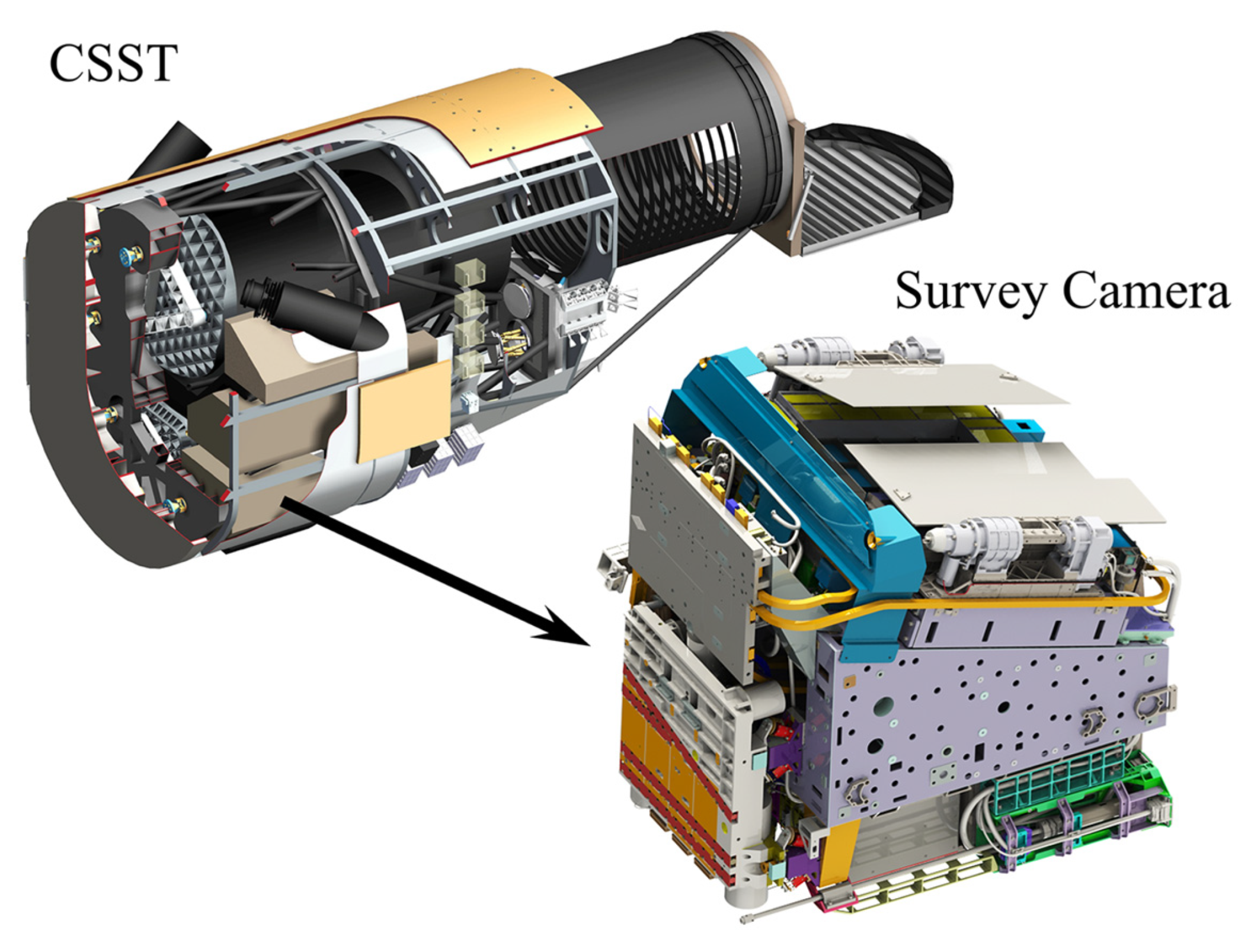
Figure 1. Cross-sectional view of the China Space Station Telescope (CSST) and Survey Camera (SC).
Aerospace 12 01036 g001
Figure 2. Mechanical architecture of the Survey Camera (SC).
Aerospace 12 01036 g002
Figure 3. Mechanical mounting interfaces (A, B, C, and D Mounting Interfaces) between the China Space Station Telescope (CSST) and Survey Camera (SC).
Aerospace 12 01036 g003
Figure 4. Iterative optimization process of Main Structure (MST) configurations.
Aerospace 12 01036 g004
Figure 5. Main components of the Main Structure (MST).
Aerospace 12 01036 g005
Figure 6. Schematic illustration of the carbon fiber layup process for the Main Structure (MST).
Aerospace 12 01036 g006
Figure 7. Titanium alloy embedded parts of the Main Structure (MST).
Aerospace 12 01036 g007
Figure 8. Block division and structural optimization of the MST’s main frame structure.
Aerospace 12 01036 g008
Figure 9. Finite element model of the Survey Camera (SC), constructed using a hybrid modeling approach with multiple element types.
Aerospace 12 01036 g009
Figure 10. Overall fundamental frequency of the SC under ABCD interface constraint.
Aerospace 12 01036 g010
Figure 11. Local thickening optimization of carbon fiber plies in the Main Structure (MST).
Aerospace 12 01036 g011
Figure 12. Reinforcement optimization of titanium alloy inserts in the Main Structure (MST).
Aerospace 12 01036 g012
Figure 13. Block A of the Main Structure (MST) in the pre-curing state.
Aerospace 12 01036 g013
Figure 14. Machining process of the Main Structure (MST).
Aerospace 12 01036 g014
Figure 15. Free modal test setup of the Main Structure (MST).
Aerospace 12 01036 g015
Figure 16. Frequency response curve of the Main Structure (MST) under free boundary conditions.
Aerospace 12 01036 g016
Figure 17. First five-order modal shapes of the Main Structure (MST) under free boundary conditions.
Aerospace 12 01036 g017
Figure 18. Measurement Reference (MR) system of the Main Structure (MST) and Focal Plane Array (FPA).
Aerospace 12 01036 g018
Figure 19. Calibration setup for the Measurement References (MRs) of the Main Structure (MST).
Aerospace 12 01036 g019
Figure 20. Qualification-level vibration test setup of the Main Structure (MST).
Aerospace 12 01036 g020
Figure 21. Ultrasonic flaw detection of the Main Structure (MST) post-vibration test.
Aerospace 12 01036 g021
Figure 22. Main integration process of the Survey Camera (SC).
Aerospace 12 01036 g022
Figure 23. Vibration test of the Survey Camera (SC).
Aerospace 12 01036 g023
Figure 24. Measurement setup for the relative angle and position between the Focal Plane Array (FPA) Measurement Reference (MR) and Main Structure (MST) MR after the vibration test.
Aerospace 12 01036 g024
Figure 25. Schematic diagram of the composition of the thermovacuum test system.
Aerospace 12 01036 g025
Figure 26. The thermovacuum test of the SC.
Aerospace 12 01036 g026
Table 1. The vacuum outgassing properties of M55J carbon fiber/cyanate ester resin composites.
Project CategoryValue
Total Mass Loss (TML)0.114%
Condensable Volatile Content (CVC)0.009%
Water Vapor Regain (WVR)0.099%
Table 2. Thickness distribution of carbon fiber plies in various parts of the MST.
AreaThickness of Plies
Block ACube Mold 1.6~3.2 mm
Outer Skin4.0 mm
Block BCube Mold 1.6~3.2 mm
Outer Skin4.0 mm
Block CCube Mold 1.6~3.2 mm
Outer Skin4.0 mm
Block DCube Mold 1.6~3.2 mm
Outer Skin4.0 mm
Shutter Support BaseCube Mold 1.6~3.2 mm
Outer Skin3.2 mm
ROEs Support BeamCube Mold 3.2~4.0 mm
Outer Skin5.6 mm
Auxiliary Support Beam5.6 mm
Table 3. Mechanical strength performance of the MST.
Analysis CategoryAnalysis ItemValue (MPa)Allowable Value (MPa)Safety Margin
Sine
Vibration
Maximum longitudinal stress of carbon fiber layers132.35001.80
Maximum transverse stress of carbon fiber layers2.4205.17
Maximum shear stress of carbon fiber layers2.45014.43
Maximum von Mises stress of titanium alloy inserts220.18001.69
Random
Vibration
Maximum longitudinal stress of carbon fiber layers140.55001.64
Maximum transverse stress of carbon fiber layers2.8204.29
Maximum shear stress of carbon fiber layers2.4505.17
Maximum von Mises stress of titanium alloy inserts265.38001.23
Table 4. Modal frequencies and mode shapes of the MST under free boundary.
Modal OrderMeasured (Hz)Simulated (Hz)DeviationMode Shape
1st330.6354.57.2%1st Torsional
2nd348.4369.56.1%2nd Torsional
3rd507.5547.27.8%1st Radial
4th661.0624.1−5.6%2nd Radial
5th702.8675.9−3.8%Bending
Table 5. Vibration test conditions of the SC.
Sine Vibration-X
Frequency Range (Hz)5~1010~1414~3030~4545~100
Amplitude7.45 mm3.0 g4.5 g6.0 g4.0 g
Sweep Rate2 oct/min
Sine Vibration-Y, Z
Frequency Range (Hz)5~1010~1414~6060~100
Amplitude9.93 mm4.0 g6.0 g4.0 g
Sweep Rate2 oct/min
Random Vibration-X, Y, Z
Frequency Range (Hz)20~100100~600600~2000
Power Spectral Density (PSD)3 dB/oct0.02 g2/Hz−9 dB/oct
Root Mean Square (RMS)4.02 g
Test Duration per Direction3 min
Table 6. Measurement results between the FPA-MR and MST-MR.
ItemsDirectionBefore Vibration TestAfter Vibration TestDifference
Angles of FPA-MR Relative to MST-MRX1.3674°1.3681°2.5″
Y340.4″345.8″5.4″
Z−20.5″−25.7″−5.2″
Positions of FPA-MR Relative to MST-MRX393.500 mm393.521 mm21 μm
Y564.548 mm−564.552 mm−4 μm
Z−816.868 mm−816.846 mm22 μm
Disclaimer/Publisher’s Note: The statements, opinions and data contained in all publications are solely those of the individual author(s) and contributor(s) and not of MDPI and/or the editor(s). MDPI and/or the editor(s) disclaim responsibility for any injury to people or property resulting from any ideas, methods, instructions or products referred to in the content.