Article

Inertia Parameter Identification of Non-Cooperative Targets via Motion Estimation

1
State Key Laboratory of Mechanical System and Vibration, School of Mechanical Engineering, Shanghai Jiao Tong University, Shanghai 200240, China
2
Beijing Institute of Control Engineering, Beijing 100190, China
*
Author to whom correspondence should be addressed.
Aerospace 2025, 12(11), 995; https://doi.org/10.3390/aerospace12110995
Submission received: 28 September 2025 / Revised: 30 October 2025 / Accepted: 5 November 2025 / Published: 7 November 2025

Abstract

In space missions, particularly in on-orbit servicing (OOS) missions, many tasks involve non-cooperative targets. To ensure the safety and precision of such missions, complete identification of the target’s inertia parameters is essential. This paper proposes a novel method for identifying the inertia parameters of a non-cooperative target, introducing an innovative approach to position and velocity estimation based on a time-of-flight (TOF) camera. The paper first describes the physical configuration of the system, followed by the overall identification process of the target. Subsequently, all inertia parameters are reviewed, and the associated data processing procedures are presented. The (angular) momentum of both the satellite and the manipulator is calculated to make preparations for subsequent identification steps. The motion parameters of the target are estimated using the Kalman filter (KF) and extended Kalman filter (EKF), with newly designed models for position and velocity. Furthermore, a novel full-parameter identification method is proposed, building upon the preceding motion estimation process. Simulations show that the identification errors of all inertia parameters are less than 0.3%, which validates the correctness and effectiveness of the proposed methods.

1. Introduction

It is essential to identify the physical parameters—particularly the inertia parameters—prior to mission execution to ensure safety and reliability.
In recent years, OOS has been receiving increasing attention [1,2,3]. Typical OOS missions include refueling operations, fault diagnostics and resolution, satellite retrieval, and debris mitigation [4,5,6]. Depending on the nature of the target, these missions can be classified into operations involving cooperative targets and non-cooperative targets. Missions involving non-cooperative targets are considerably more challenging due to the lack of cooperation from the targets. In addition, the unknown physical parameters of such targets result in uncertain dynamics, thereby increasing the operational risks. Consequently, it is essential to identify the physical parameters—particularly the inertia parameters—prior to mission execution to ensure safety and reliability.
To identify all the inertia parameters, the first step is to estimate the position and attitude of the target. At present, various types of sensors can be employed for target observation, including visible light camera [7], TOF camera [8], infrared camera [9], laser radar [10], etc. Considering that the illumination conditions in space are often uncontrollable, TOF camera or laser-based sensors are generally preferred. Once point clouds are sampled, several approaches can be used to determine the position and attitude of the target. These methods are typically classified into two categories: global registration and local registration. Global registration methods generally provide an initial rough estimation of the transformation matrix between two sets of point clouds. Common techniques include Random Sample Consensus (RANSAC) combined with Fast Point Feature Histograms (FPFH) [11], 4-Point Congruent Sets (4PCS) [12], and Fast Global Registration (FGR) [13], etc. The optimization function of the mostssss commonly used global registration method FGR is seen in Equation (1). Local registration methods often achieve higher accuracy but are sensitive to initial conditions and prone to convergence toward local minima. The iterative closest point (ICP) method [14,15] is widely used due to its simplicity, efficiency, and accuracy. In this study, the ICP method is adopted since point clouds do not require global registration.
E ( R , t ) = ( p i ,   q i ) C ρ R p i + t q i 2
where P = {pi} is the source point cloud, Q = {qi} is the target point cloud, R is the rotation matrix, t is the translation vector, and ρ() is the robust loss function.
After the completion of point cloud registration, it is necessary to estimate the target’s motion state before identifying its inertia parameters. Approaches to target motion estimation are generally divided into two principal categories: image-based methods and filter-based methods. Regarding imaged-based methods, Scharr et al. [16] proposed a model for simultaneous estimation of full 3D motion and 3D positions in world coordinates from multi camera sequences. Shakernia et al. [17] presented an algorithm for infinitesimal motion estimation from multiple central panoramic views based on optical flow equations. Haller et al. [18] introduced a highly robust and precise global motion estimation (GME) approach using motion vectors (MVs), which enables accurate short-term global motion parameter estimation. However, these image-based techniques primarily estimate positional information and are generally unable to determine the target’s attitude. As for filter-based methods, Yang et al. [19] proposed a dual Kalman filter framework to sequentially estimate the position and attitude parameters of a target. Olama et al. [20] utilized signal strength and wave scattering models to estimate the position and velocity of the target. De Jongh et al. [21] used a stereo–camera pair to extract distinct surface features via the scale invariant feature transform (SIFT) and adopted an EKF to estimate the position, attitude, velocity, and moments of inertia of the target. Tweddle et al. [22] proposed a comprehensive approach combining factor graph and Multiplicative extended Kalman Filter (MEKF) to identify both the pose and partial inertia parameters of the target.
If the target has been captured, all its inertia parameters can be identified utilizing manipulators or another mechanism capable of altering the pose of the whole system [23,24,25]. Murotsu et al. [26] employed the least squares method (LSM) to determine the inertia parameters of the target by adjusting the pose of the arm body system after the target was securely fixed. The core LSM equation can be seen in Equation (2). Zhang et al. [27] used a tethered system to approach and capture the target, identifying the full set of inertia parameters based on the dynamics response of the target. Nguyen-Huynh et al. [28] employed a base minimum-disturbance control strategy to modify the attitude of the entire system, thereby enabling the identification of all inertia parameters. Wu et al. [29] proposed an inertia matrix identification approach that integrates a structure optimization strategy. Their method effectively enhances the computational efficiency of DNN-based inertia estimation under complex measurement noise. Platanitis et al. [30] presented an inertia parameter estimation framework for cargo-carrying spacecraft based on causal learning, which enables parameter identification without prior knowledge of the system’s state following a deployment event. However, these capture-based methods involved high-risk operations due to the unknown dynamics of the target, making them less desirable. On the other hand, many studies have explored methods that do not require target capture. Matthew et al. [31,32] proposed an architecture for estimating dynamic states, geometric shapes, and model parameters; however, their approach can only identify the normalized principal moments of inertia. Richard et al. [33] estimated the inertia parameters of a space object using photometric and astrometric data. Sheinfeld et al. [34] presented a general framework that could estimate the inertia of any rigid body. While valuable, the three methods are limited to identifying normalized inertia parameters rather than full inertia matrices. Meng et al. [35] extended Matthew’s work by employing a touch probe to make physical contact with the target and applying the impulse theorem to achieve full identification of all inertia parameters. Their main identification equation is shown in Equation (3). Mammarella et al. [36] introduced a recursive algorithm that combines physics-based modeling with black-box learning techniques to improve the accuracy and reliability of spacecraft inertia estimation, enhancing convergence toward true values. Baek et al. [37] proposed a fast, learning-based inertia parameter estimation framework capable of modeling the dynamics of unknown objects using a time-series, data-driven regression model, which significantly improves identification speed.
U p ˙ U L K U = P K U ω i U × 0 P K U × 0 [ # U ω i ] 1 m U a U U I r r U
Δ j = m b Δ v b Δ l = T ( q p ) ( 1 ) I b ω b ( 1 ) T ( q p ) ( 0 ) I b ω b ( 0 )
where the identified parameters include the mass mU, position vector UaU, and six-dimensional inertia vector UIrr.
In this paper, a novel position and velocity estimation method is proposed to facilitate the identification of inertia parameters. Since filter-based approaches are capable of estimating a broader range of motion parameters, both the KF and EKF are employed. Unlike conventional methods, which require reconstructing the entire target model to determine its geometric center [31,32,33,34,35], the proposed method relies solely on point cloud data captured by the camera at a given moment, making it more general and practical for non-cooperative targets. Furthermore, this paper introduces a new method for identifying the complete set of inertia parameters of a non-cooperative target. Traditional approaches typically construct an LSM equation involving a 10-dimensional parameter vector and require continuous contact monitoring using a force sensor, or at least three collisions in the absence of one [23,24,25,26,27,28]. In contrast, the proposed method eliminates the need for a force sensor and reduces the identification process to only two parameters after visual processing. As a result, it requires merely a single instance of contact with the target to identify all remaining unknown inertia parameters, significantly simplifying the identification procedure.
The structure of this paper is organized as follows: First, Section 2 briefly introduces the hardware system and the identification process for the non-cooperative target. Second, Section 3 presents the procedure for processing the collected data, as well as the newly proposed approach for non-cooperative target identification based on a novel position and velocity estimation method. Third, simulations are performed and analyzed in Section 4. Finally, Section 5 is illustrated.

2. System Overview

2.1. Physical Composition

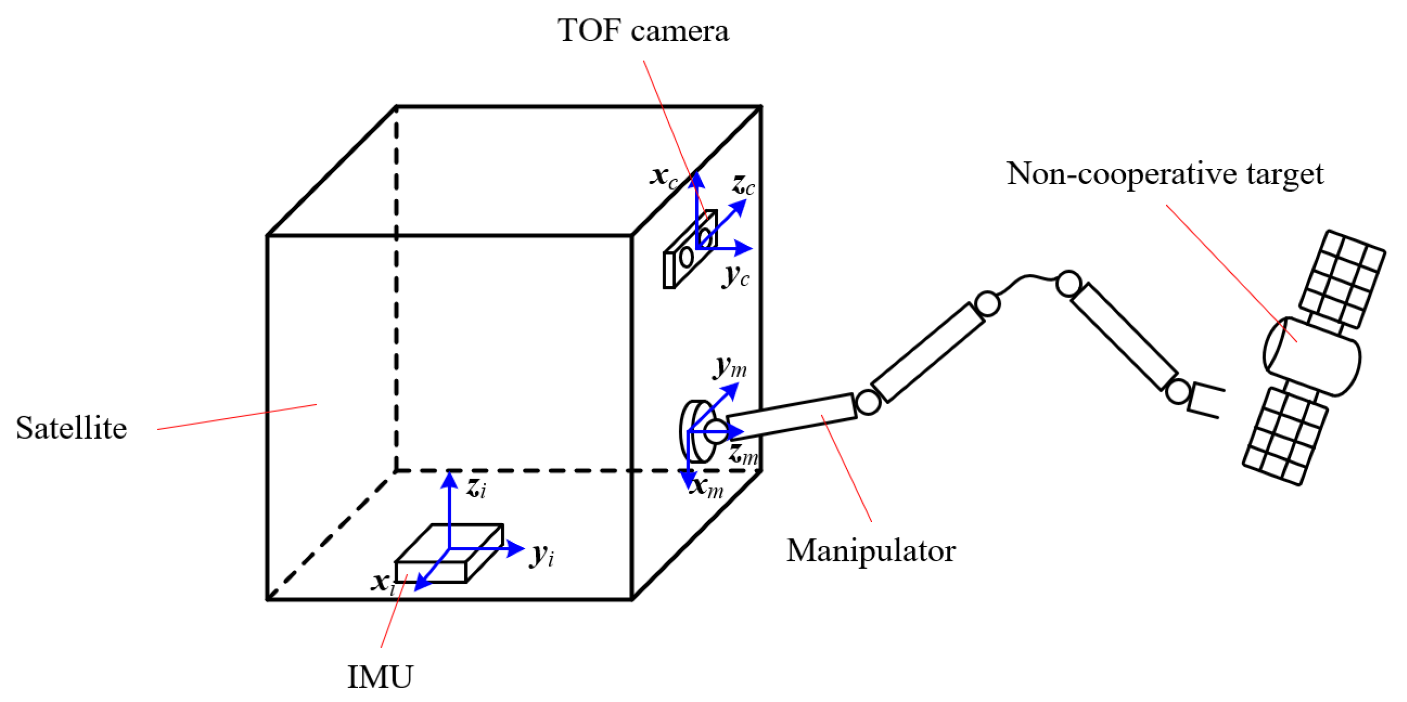
The whole simulation system includes a 7-degree-of-freedom (7 DOF) manipulator, the main satellite, an inertial measurement unit (IMU), a TOF camera, and the non-cooperative target, as illustrated in Figure 1.
The satellite is a common servicing facility that can execute various kinds of space missions. But in this paper, it is only utilized to approach the target, and then all the thrusters will stop working. After that, it can be seen as a rigid body without other forces and moments except that exerted by the manipulator. In this case, the manipulator and satellite will make contact with the target at a lower initial velocity for subsequent parameter identification using momentum conservation.
The IMU mounted on the satellite is used to estimate the (angular) velocity, position, and attitude using a related filtering algorithm. The TOF camera, also mounted on the satellite, can collect visual data such as point clouds and depth maps of the non-cooperative target.
The 7-DOF manipulator, whose base is connected to the satellite, is capable of performing multiple precise space operations. In this paper, it is required to contact the target several times.
The non-cooperative target is a free-floating object whose physical properties are completely unknown and must be identified. In this paper, the main task is to identify all the inertia parameters of the target for future operations.

2.2. Identification Process

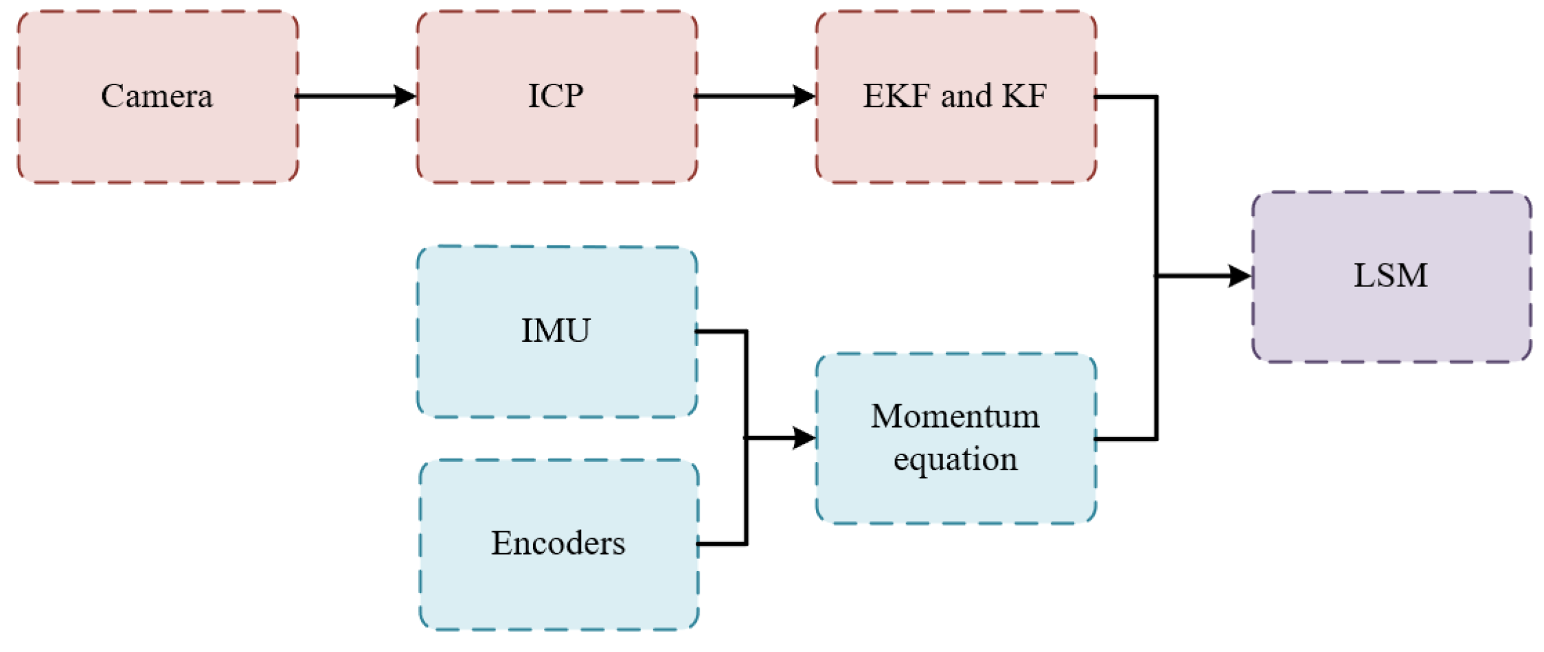
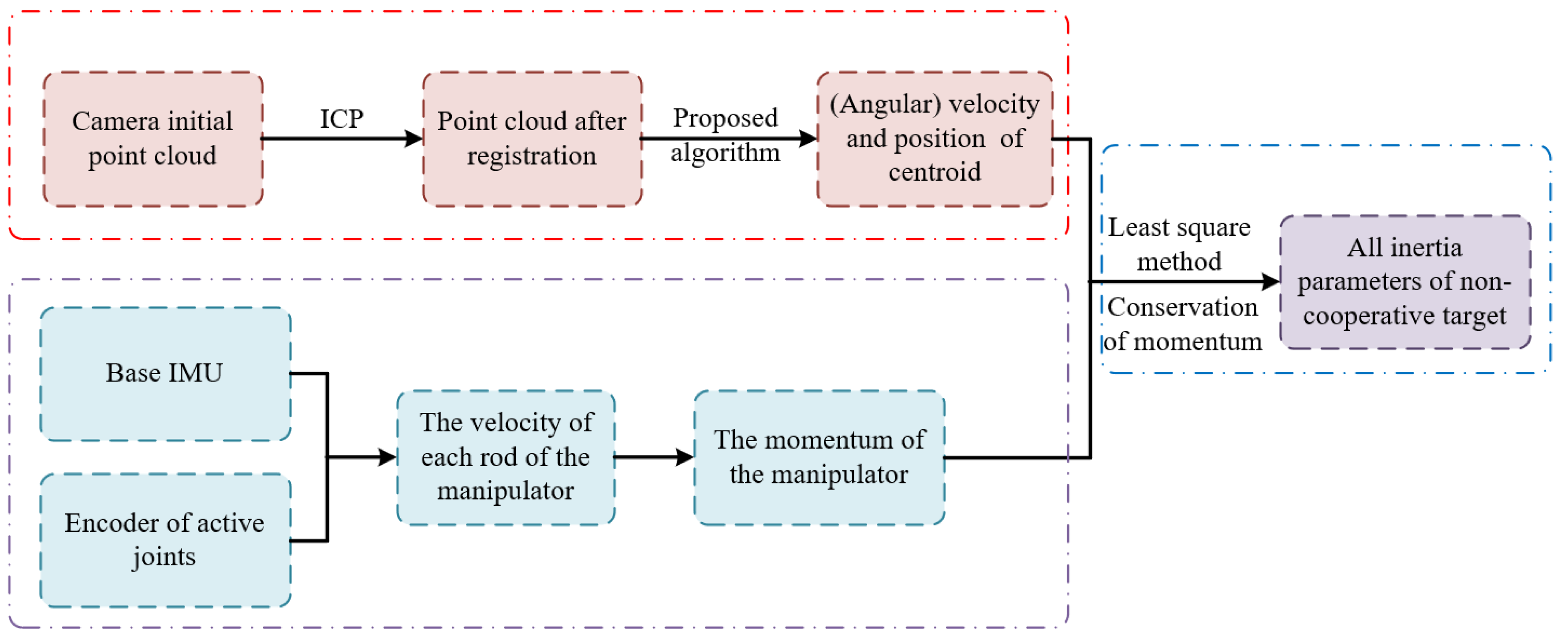
The overall identification process and data flow can be seen in Figure 2 and Figure 3. First, when the manipulator approaches the non-cooperative target within an appropriate distance, the camera begins to work. The collected point cloud data must be preprocessed before being utilized. During this stage, the ICP method is employed to continuously calculate the registration matrix between the initial point cloud and the newest one. Second, a novel method is proposed to estimate both the (angular) velocity and centroid of the point cloud. Meanwhile, based on data from the base IMU and motor encoder, the (angular) velocity of each rod can be derived through forward kinematics [38]. Therefore, the total (angular) momentum of the manipulator can be calculated. Third, after some deductions, the relationship between the target’s inertia parameters and the known parameters before and after the contact is established. Finally, LSM is adopted to estimate the complete set of inertia parameters of the target.

3. Methods

3.1. Descriptions of the Inertia Parameters

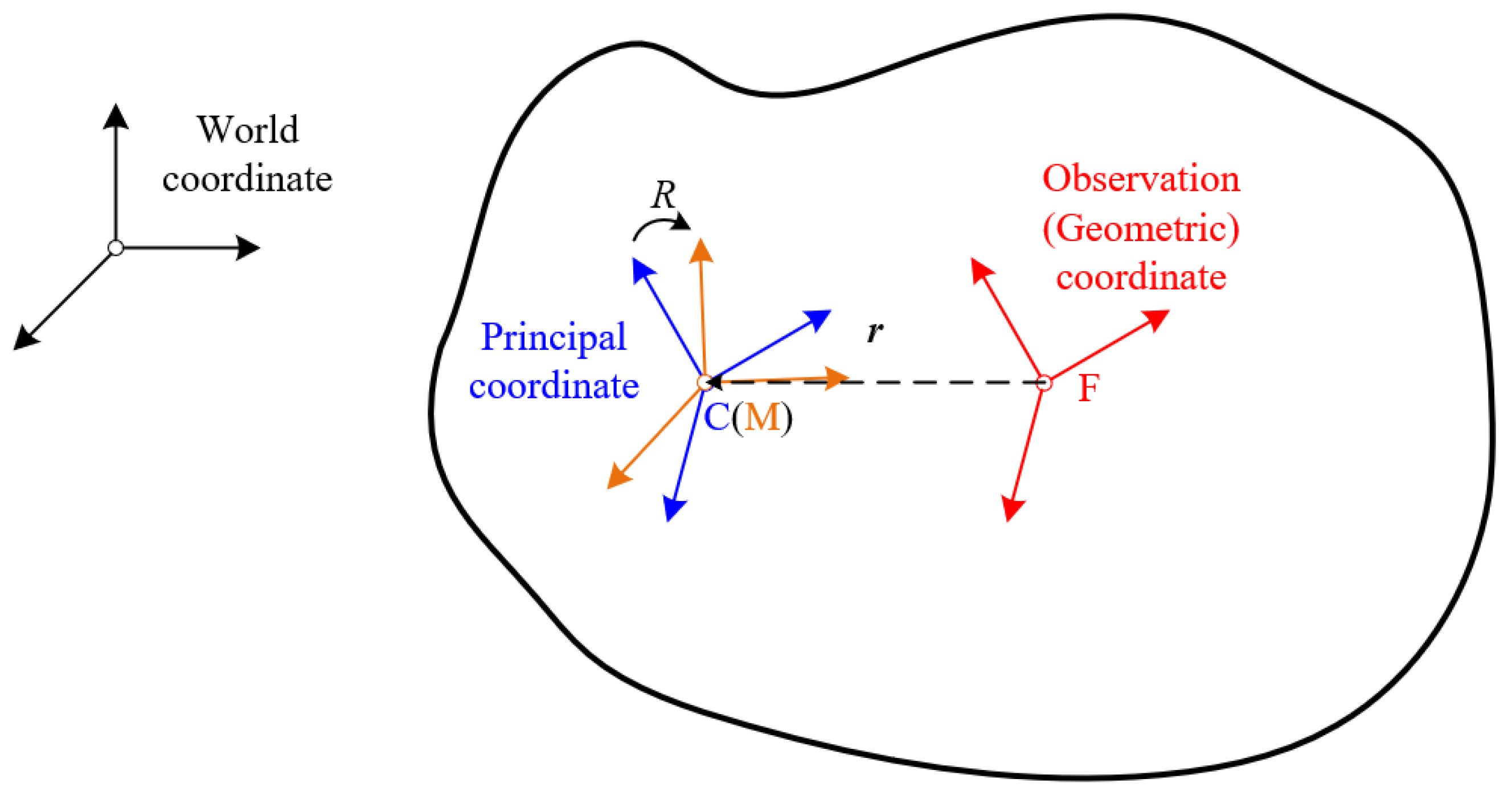
For a rigid body, its inertia parameters include the mass m, centroid position r, and the inertia matrix I. As can be seen in Figure 4, the target has its own principal coordinate frame, which is established at the centroid of the target. Here, it is assumed that the principal coordinate and the geometric coordinate share the same posture. In the target’s principal coordinate, the inertia matrix contains only the three principal moments of inertia along the main diagonal of the matrix, which can be expressed as IC = diag(I1, I2, I3). However, in many cases, the target’s motion cannot be analyzed in the principal coordinate. As a consequence, the inertia matrix is transformed into Equation (4) according to the principal of conservation of energy.
I M = R I C R T
where R is the rotational matrix from the observation coordinate to the principal coordinate.
It can be inferred from Equation (4) that the inertia matrix is always symmetric. This implies that the matrix contains 6 independent elements, comprising 3 principal moments of inertia and 3 products of inertia defined in Equation (5), when the matrix is described in a non-principal coordinate.
I M = I x x I x y I x z I x y I y y I y z I x z I y z I z z
Furthermore, if the analyzed point is not located at the centroid, the actual inertia matrix will vary accordingly. The inertia matrix at point F relative to that of point C can be formulated as shown in Equation (6). From this perspective, the inertia matrix can be solved and transformed to any coordinate frame.
I F = I C + m r F C T r F C E 3 r F C r F C T
where rFC represents the vector from point F to point C, and E3 denotes a 3-dimension unit matrix.

3.2. Data Collection and Processing

3.2.1. Visual Data

A depth camera is employed to observe the non-cooperative target once the manipulator approaches it. It is able to capture the point cloud in real time as needed.
During data processing, preprocessing includes voxel filtering, statistical filtering, and an RANSAC-based plane removal method. Then the ICP algorithm is applied to acquire the relationship between two sets of point clouds. As one of the most widely used registration algorithms, the ICP algorithm calculates the transformation matrix by minimizing the Euclidean distance between corresponding points from the two sets of point clouds. The source and target point cloud are defined as X = {x1, x2, ..., xm} and Y = {y1, y2, …, yn}, where X is the point cloud sampled at a certain moment, while Y is the point cloud sampled at the subsequent moment after X. Then, the evaluation function can be written as Equation (7).
E T f = 1 n i = 1 n y i 1 T f x i 1 2
where n is the number of corresponding point pairs, and Tf is the transformation matrix containing rotation and translation.

3.2.2. Other Data

For the manipulator, an IMU mounted on the base is essential for calculating all the kinematic parameters. Generally speaking, the IMU is composed of a three-axis accelerometer and a three-axis gyroscope. Therefore, the linear acceleration and the angular velocity of the manipulator base in the base coordinate can be obtained directly. To express these quantities in the inertial coordinate frame, it is necessary to determine the pose of the manipulator with respect to the inertial frame. The attitude quaternion qb is employed to represent the actual orientation of the manipulator base. Considering that the data obtained directly from the gyroscope is the angular velocity ωb described in the sensor coordinate system, the relationship between qb and ωb can be expressed in Equation (8).
q ˙ b = 1 2 q b 0 ω b T T
where ⊗ represents the quaternion operator, and q1q2 can be expressed as follows:
q 1 q 2 = q 2 w q 2 x q 2 y q 2 z q 2 x q 2 w q 2 z q 2 y q 2 y q 2 z q 2 w q 2 x q 2 z q 2 y q 2 x q 2 w q 1
where q2 = [q2w, q2x, q2y, q2z]T. If not specifically mentioned, the four components of any q in this paper are labeled w, x, y, z in sequence.
When qb is obtained, the rotation matrix from world coordinate to manipulator base coordinate can be calculated using function fq2r() defined in Equation (10).
f q 2 r q = 1 2 q y + 2 q z 2 2 q x q y q w q z 2 q x q z + q w q y 2 q x q y + q w q z 1 2 q x + 2 q z 2 2 q y q z q w q x 2 q x q z q w q y 2 q y q z + q w q x 1 2 q x + 2 q y 2
It should be noted that the initial value of qb is determined by the installation of the sensor, and it should be calibrated before taken into use.
On the other hand, each manipulator joint is equipped with an encoder providing its angular position. By differentiating the joint angles, the joint angular velocities can be obtained. According to the previous section, the velocity of the centroid of each rod can be derived sequentially. In addition, all sensor data must be filtered to eliminate unexpected noises.

3.3. Momentum and Angular Momentum of the Satellite and Manipulator

For simplicity, the satellite’s mass and inertia matrix are incorporated into the base of the manipulator for analysis because both the satellite and manipulator base are taken as rigid bodies, and they are fixed together. Assuming that the (angular) velocity of the centroid of each rod of the manipulator has been derived, the (angular) momentum of each rod can be calculated by Equations (11) and (12). The angular momentum calculation in Equation (12) is analyzed in the centroid coordinate of each rod.
P i = m i v i ,   i 1 , 2 , ... , n
L i = I i ω i ,   i 1 , 2 , ... , n
where n is the number of joints, mi denotes the mass of rod i, Ii denotes the inertia matrix of rod i described in the corresponding coordinate, and vi and ωi are the velocity and angular velocity in the same coordinate with Ii.
And the total (angular) momentum of the manipulator can be derived by Equations (13) and (14), assuming that the manipulator is seen as a rigid body during the whole contact process.
P t o t a l = i = 1 n m i R i w v i
L t o t a l = i = 1 n R i w I i R i w T + m i r w i T r w i E 3 r w i r w i T R i w ω i
where R i w denotes the rotation matrix from inertial coordinate to the ith coordinate, and rwi denotes the vector from the origin of world coordinate to that of the ith coordinate.
The momentum and angular momentum must be converted to the inertial frame in Equation (13) for the subsequent use of the momentum theorem.

3.4. Motion Estimation of the Target

3.4.1. Attitude Parameter Estimation

Considering that when the manipulator makes contact with the target, the camera is inactive, and the target will not exert external force (moment) during the camera’s operation. Consequently, the attitude dynamics of the target follow the torque-free Euler equation shown in Equation (15), both before and after the contact.
I t ω ˙ t + ω t × I t ω t = 0
where ωt = [ωtx, ωty, ωtz]T denotes the angular velocity, and It denotes the inertia matrix.
Particularly, if the equation is described in the principal coordinate, namely the centroid coordinate, Equation (15) can be expressed as
I 1 ω ˙ t x I 2 ω ˙ t y I 3 ω ˙ t z + 0 ω t z ω t y ω t z 0 ω t x ω t y ω t x 0 I 1 ω t x I 2 ω t y I 3 ω t z = 0
Furthermore, Equation (16) can be written as
ω ˙ t = I 2 I 3 I 1 ω t y ω t z I 3 I 1 I 2 ω t x ω t z I 1 I 2 I 3 ω t x ω t y T
where I1-I3 are the principal moments of It.
To estimate the attitude and angular velocity of the target, the EKF is employed to solve the nonlinear estimation problem. The EKF is a recursive algorithm that estimates the state of nonlinear dynamic systems by linearizing the system model around the current estimate, predicting the next state, and updating it with new noisy measurements. In this study, the state vector is defined as
x a = q t T ω t T I n T
where qt is the attitude quaternion of the principal coordinate, and In is the normalized vector of principal inertia, regulated as
I n = I ¯ 1 I ¯ 2 I ¯ 3 T = I 1 I 2 I 3 T / I 1 I 2 I 3 T 2
The observation vector here is the attitude quaternion of observation coordinate qo. As mentioned before, it equals to qt. The relationship between state vectors at adjacent moment can be expressed as
x a , k + 1 = x a , k + t k t k + 1 d q t d ω t 0 1 × 3 T
where
d q t = 1 2 q t 0 ω t T T d t d ω t = I 2 I 3 I 1 ω t y ω t z I 3 I 1 I 2 ω t x ω t z I 1 I 2 I 3 ω t x ω t y T d t
During the prediction process, the normalized principal moments of inertia remain constant and are subsequently adjusted toward their true values during the update process. Since both the quaternion and the moments are subject to normalization constraints, they must be normalized additionally in each iteration.

3.4.2. Position and Velocity Estimation

Ordinarily, multiple sets of point clouds must be utilized to reconstruct the target model prior to parameter identification, which can be time-consuming. In such approaches, the geometric center of each point cloud is typically used as the measurement input for the KF to estimate the position and velocity of the non-cooperative target. In contrast, the proposed method eliminates the need for target model reconstruction and directly utilizes ICP results to estimate the target’s position and velocity.
As described before, the transformation matrix between two sets of point clouds can be estimated. However, the data is collected in the coordinate of the camera, which is not continuously at a standstill. Consequently, the two set of point clouds have to be transformed to a consistent inertial coordinate. The ith point of the transformed point cloud can be written as
p i w 1 = T b w T c b p i c 1
where superscript w denotes the world coordinate or other inertial coordinate, while c denotes the camera coordinate; T b w denotes the transformation matrix from the world coordinate to the coordinate of the manipulator base; and T c b denotes the matrix from the manipulator base to the camera.
We can assume that the transformation matrix between the point clouds corresponding to time t1 and t2 after transformation to the inertial frame is T, which can also be written as Equation (23).
T = R t r 0 1
where R is the 3 ×3 rotational matrix in the upper left corner of T, while tr is the 3 × 1 displacement vector in the upper right corner of T.
As can be seen in Figure 5, at time t1, a certain point of the non-cooperative target is p1, its corresponding point at time t2 is p2, the centroids of the target at t1 and t2 are pc1 and pc2, respectively, and the origin of the inertial coordinate is w.
As no external force acts on the target, the motion of its centroid is a uniform linear motion. Let the velocity vector of centroid be vpc and the position vector from the centroid to a feature point be r. Then, vectors p1 and p2 can be expressed as Equation (24).
p 1 = p c 1 + r p 2 = p c 2 + R 12 r
Due to the fact that pc2 = pc1 + (t2t1)vpc, the relationship between p1 and p2 can be further modified as Equation (25).
p 2 1 = R 12 p c 1 + ( t 2 t 1 ) v p c R 12 p c 1 0 1 p 1 1
The rotational matrix R12 in Equation (25) is the same matrix calculated in Equation (23). Therefore, according to the corresponding elements, the following can be obtained:
t r = E 3 R 12 p c 1 + ( t 2 t 1 ) v p c
Divide both sides of Equation (26) by (t2t1) simultaneously and rearrange it, and Equation (27) can be derived.
E 3 R 12 t 2 t 1 E 3 p c 1 v p c = t r
The format of Equation (27) can be written as z = H⋅x, where z denotes the observation vector, and xp= [pc1, vpc]T is the state vector to be estimated. The coefficient matrix H includes a rotational matrix, R12, which must be obtained according to the previous section instead of directly from the registration value. As the attitude quaternion qt has been acquired, R12 can be obtained by Equation (28).
R 12 = f q 2 r q t 1 1 q t 2
Then EKF is also used here to estimate the state vector xp. Considering that xp does not change with time, it satisfies
x p , k + 1 = x p , k
It should be noted specifically that the pc1 to be estimated here denotes the centroid of the target described in the world coordinate. This means that the centroid position vector r in Figure 4 cannot be estimated directly by the proposed method. However, since the position vector of the observation coordinate in world coordinate ro is known, r can be derived by Equation (30) when necessary.
r = p c r o

3.5. Identification of the Full Inertia Parameters of the Non-Cooperative Target

In general, methods based on the momentum theorem require data from force sensors, whereas those relying on the conservation of momentum typically necessitate at least three contact instances with the target, and the dimensionality of the corresponding vector can reach up to ten. In contrast, the proposed method requires only a single instance of contact with the target, and the dimension of the unknown parameter vector is reduced to two, resulting in improved convergence speed and robustness.
As analyzed before, the momentum and angular momentum of the manipulator are measured and calculated by existing devices. When it comes to the non-cooperative target, the parameters can be expressed as follows:
P t w = m t v t w L t w = m t r t w × v t w + I t w ω t w
where the subscript t represents the parameters of the target, and superscript w means the variables are expressed in the world coordinate. w will be neglected in the following equations.
To analyze the problem, time t1 and t2 are two moments selected before and after the contact, and parameters with superscript 1 and 2 represent elements at t1 and t2, respectively. Then, the momentum and angular momentum described in the inertial coordinate can be written as follows:
a )   P t 1 = m t v t 1 b )   P t 2 = m t v t 2 c )   L t 1 = m t r t 1 × v t 1 + R 1 I t c ω t 1 c d )   L t 2 = m t r t 2 × v t 2 + R 2 I t c ω t 2 c
where superscript c denotes the centroid coordinate.
The vector cross product operation can be transformed into matrix multiplication utilizing the antisymmetric matrix of the former vector. To avoid confusion, the antisymmetric matrix of vector a in a subsequent paper is represented as f a , defined in Equation (34). Then, Equation (32) can be written as follows:
a )   P t 1 = m t v t 1 b )   P t 2 = m t v t 2 c )   L t 1 = m t f r t 1 v t 1 + R 1 I t c ω t 1 c d )   L t 2 = m t f r t 2 v t 2 + R 2 I t c ω t 2 c
f a = 0 a z a y a z 0 a x a y a x 0 ,   a = a x a y a z T
Since the initial (angular) momentum of the target is unknown, subtract (33b) from (33a) and subtract (33d) from (33c), and the following can be obtained:
Δ P t = m t Δ v t Δ L t = m t f r t 2 Δ v t + m t f Δ r t v t 1 + R 2 I t c Δ ω t + Δ R I t c ω t 1 c
Considering that the manipulator and the non-cooperative target are seen as a whole, and no external forces or moments act on it, the principal of conservation of momentum applies. Accordingly, the change in the target momentum ΔPt is equal to the opposite of the change in the momentum −ΔP of the manipulator. The following can be derived from the momentum equation in (35):
Δ P = m t Δ v t
The following can then be derived according to the conservation of angular momentum:
f r t 2 Δ P Δ L = f Δ r t v t 1 R 2 h Δ ω t + Δ R h ω t 1 c m t I ^ t
where I ^ t = [ I x x I y y I z z ] T is the vector containing all three principal moments of the inertia matrix It; function h() helps to exchange the parameters’ position, which satisfies I v = h v I ^ .
Function h() in Equation (38) can then be derived.
h v = v 1       v 2       v 3
In addition, as the normalized three principal moments of inertia have been estimated by the EKF, Equation (37) can be further simplified to
f r t 2 Δ P Δ L = f Δ r t v t 1 R 2 h Δ ω t + Δ R h ω t 1 c I n m t k
where k is the ratio of the true vector to the normalized one.
In the end, with Equations (36) and (39), the total formula between the whole inertia parameters and the known parameters is organized in Equation (40).
Δ P f r t 2 Δ P Δ L = Δ v t 0 3 × 1 f Δ r t v t 1 R 2 h Δ ω t + Δ R h ω t 1 c I n m t k
To this extent, the formula above can be written as Y = KX. By conducting multiple contacts, the LSM is then utilized to estimate all the inertia parameters.
As for the coefficient matrix K, it is necessary to perform rank analysis on it to ensure observability of the identification. Rewrite block matrix K in Equation (41).
K = a 0 3 × 1 b c
Matrix K can be divided into two column vectors, v1 = [aT bT]T and v2 = [01∗3 cT]T. If v1 and v2 are linearly independent, then K is a column of full rank, and the parameters to be identified are observable.
Assuming v1 and v2 are linearly correlated, the following can be derived:
λ ,   0 3 × 1 = λ a   and   c = λ b
Considering that a = −Δvt is not a zero vector, λ must equal 0. But vector c is also not a zero vector. Consequently, c cannot be equal to λb in this case. In other words, the rank of matrix K is full, and the parameters mt and k to be identified are observable within one contact.
Taking the first line of Equation (40) for analysis, it can be found that the changes in momentum and those in velocity are linearly correlated, and the coefficient is mt. Consequently, the fitted mt must be positive to keep the trends of the two changes consistent. On the other hand, the second line of Equation (40) can, in fact, be divided into two parts: the angular momentum generated from translation and the angular momentum from rotation. Since mt is completely decided by a in Equation (41), the rest of Equation (40) can be revised as in Equation (43). It can be concluded that the identification of mt and k are actually independent. For the same reason, k must be a positive number.
Δ L = R 2 h Δ ω t + Δ R h ω t 1 c I n k

4. Simulations and Results

4.1. Simulation Route

For simplicity, the non-cooperative target model used in the simulation is a self-built satellite model whose complete set of inertia parameters are listed in Table 1. The parameters are set as an integer constant for convenience.
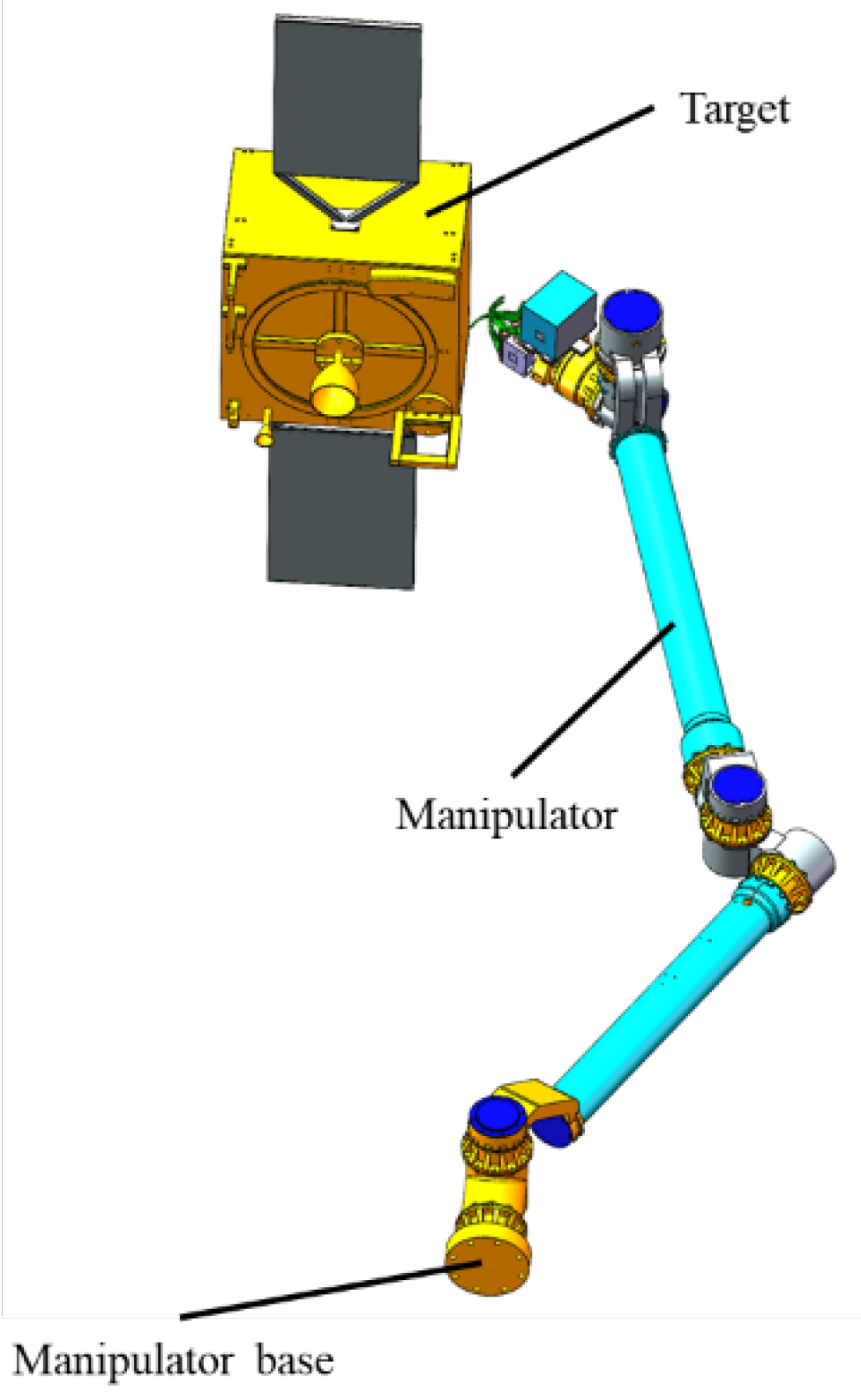
The whole simulation model is constructed in UG NX 12.0. It is composed of a servicing satellite, a manipulator, and the target, as illustrated in Figure 6, where the servicing satellite is omitted, and its physical characteristics are converted and incorporated to that of the manipulator base since the manipulator base is fixed to the servicing satellite. It is essential that the inertia parameters of both the manipulator and the servicing satellite are fully known. In addition, in a real space environment, the end of the manipulator can be made of flexible material to reduce impact forces on the target.
With the help of Simulink in MATLAB 2019b, co-simulation is conducted to simulate the contact progress of the manipulator and the target. The simulated pose data of the target is imported into Blensor to generate point clouds. The point clouds sampled are mixed with Gaussian white noises by a virtual TOF camera to simulate the measurement noises of a real camera. The sampled point clouds are then processed using relative point cloud algorithms. The motion estimation and parameter identification algorithms are then validated in MATLAB. The overall flow chart is demonstrated in Figure 7, and “UG NX 12.0”, “Blensor 1.0.18”, “MATLAB”, and “SIMULINK” represent the software and tools utilized in the simulation.

4.2. Results

4.2.1. Accuracy of ICP

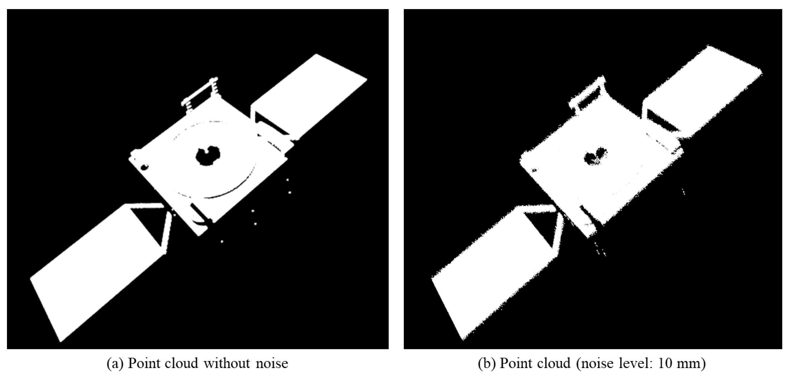
First, the effectiveness of the ICP algorithm is tested and evaluated. The parameters of a ZED camera are taken for the virtual camera. The depth capture rate is selected as 30 Hz, and the resolution is 1080p. Figure 8 shows point clouds without noise (left) and with noise (right). Several sets of point clouds are selected from the virtual camera during the simulation, and the transformation matrices from the first set to the other sets are derived. To quantitatively analyze errors, the position error is defined as the norm of the difference between the theoretical and the actual position vectors, and the attitude error is calculated as shown in (44).
Δ θ r a d = arccos trace R d R a T 1 2 π 180
where Rd represents the desired rotation matrix, and Ra represents the matrix from registration.
To analyze the impact of different noise levels possible in the registration period, the accuracy of the ICP is evaluated under three noise conditions. The standard deviations of the white noise added to the point clouds are 2 mm, 5 mm, and 10 mm, respectively.
In Table 2, the position and attitude errors of the target obtained from the ICP increase with the noise level increase. However, the method demonstrates a certain degree of robustness since the errors remain within the same order of magnitude.
Since identification of inertia parameters is not a continuous process and does not need real-time performance, the set of point clouds sampled each time is stored, and all the data are processed at last for identification.

4.2.2. Accuracy of Attitude Parameters

Since the estimation of attitude parameters utilizes the EKF, the initial values of xa, Pa, Qa, and Ra have to be considered. The initial values of them are seen in Table 3.
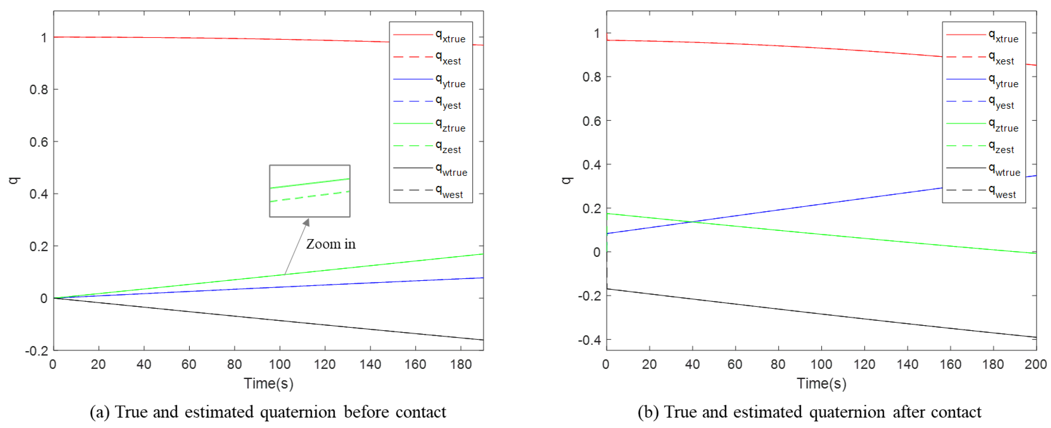
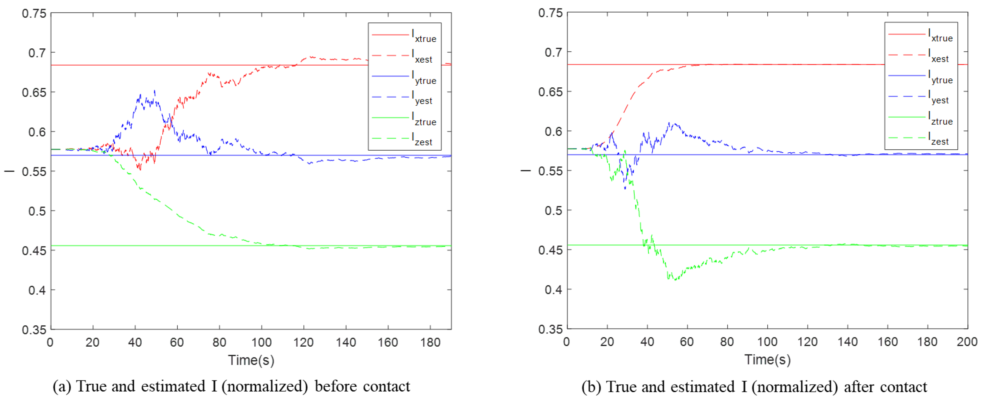
Set the noise level of the point cloud here to 10 mm; the complete results of the attitude estimation are seen in Figure 9, Figure 10 and Figure 11. The sampling rate is 10 Hz, and the simulation step is 1 ms. The subscripts x, y, z, and w represent the different component of the vector in sequence, variables with subscript ‘true’ represent the preset true values in the simulation, and those with subscript ‘est’ represent the estimated values by the EKF. It is clear that the quaternion, angular velocity, and normalized principal moments of inertia all converge to their true values.
To quantitatively evaluate the estimation accuracy, the errors of qt and ωt are defined in Equation (45). The errors of qt, ωt, and It under different noise levels are shown in Table 4. Simulation under each noise is conducted 10 times, and the results are averaged. The error of each variable is calculated using its mean value after convergence to a steady state in the simulation. It can be seen in Table 4 that the attitude parameters all present good performance even if the noise level increases to a high level, and the growth of the errors is slower than the increase in noise intensity.
e q = q t q e s t 1 e θ = 2 arccos e q , w e ω = ω t ω e s t ω t × 100 %
where eq is the direct error vector of qt, eθ is the error angle, and eω is the error of ωt.

4.2.3. Accuracy of Position and Velocity Estimation

Considering that the observation coefficient matrix of the KF for position and velocity estimation is directly affected by the attitude estimation, the identification of position and velocity can be executed only after the attitude parameters have been identified correctly. The initial values of xp, Pp, Qp, and Rp are listed in Table 5.
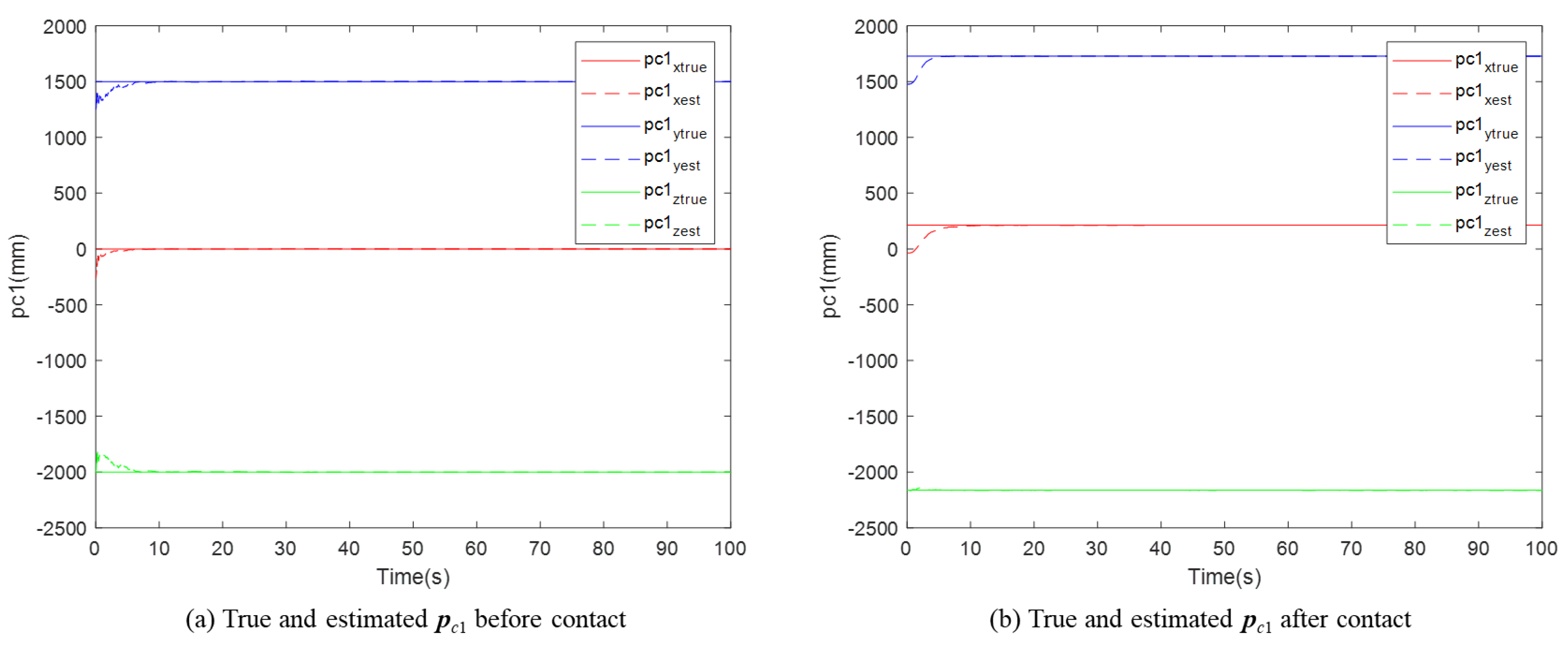
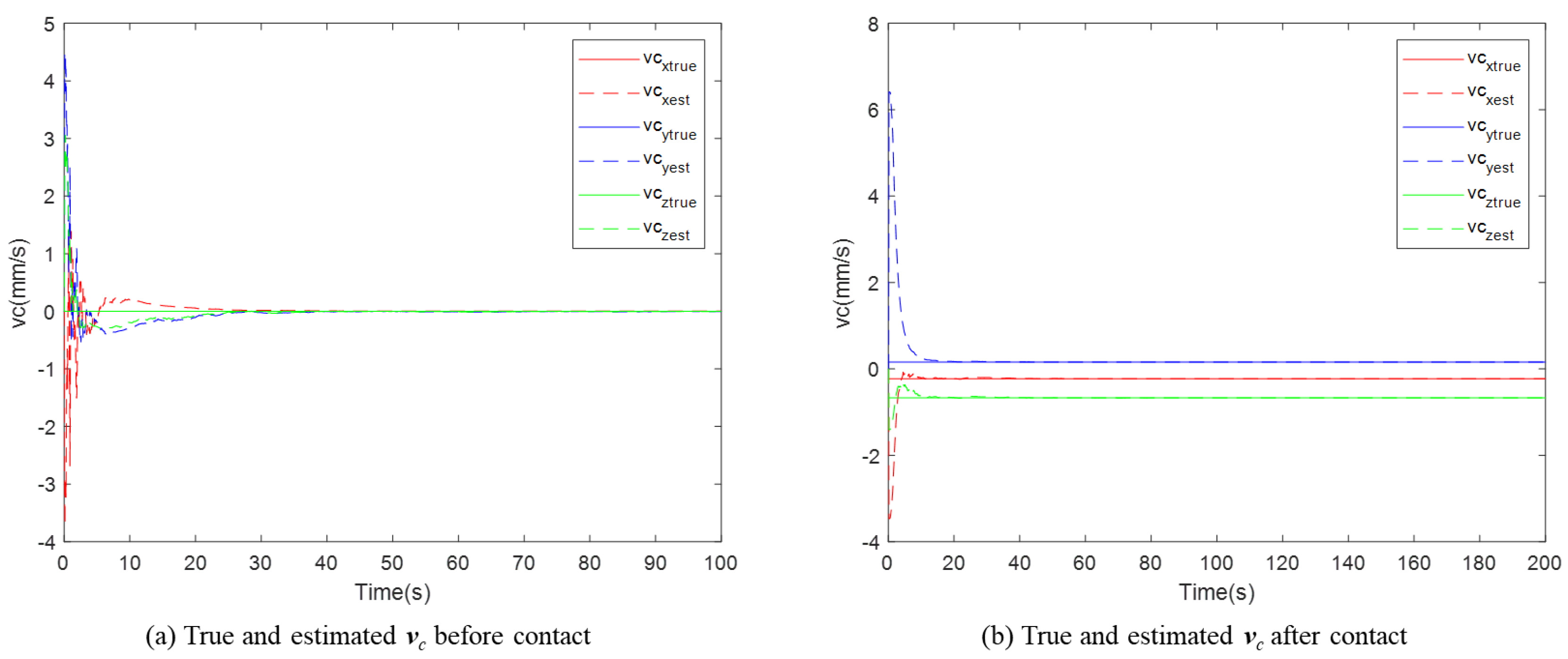
The noise level is also set as 10 mm, consistent with the previous section, and the corresponding simulation results are shown in Figure 12 and Figure 13. It can be seen that both parameters pc1 and vc will cause the true values to quickly converge despite the presence of noises.
The estimation errors of pc1 and vc are presented in Table 6. Since the initial value of vc in the simulation is set to 0, the estimation error of it before and after contact cannot be expressed consistently. As a result, the absolute error is used for the pre-contact phase, while the relative error is adopted for the post-contact phase. It can be seen that despite the noises, the KF does deliver a good performance. Moreover, compared with the attitude parameters, the observation variables for position and velocity estimation are linearly related to the state vector. Consequently, the identification process in this section utilizes the common KF, and the results are better than that of attitude parameters.
Once the identification value of the centroid position pc1 at a certain moment t1 is determined, the real-time centroid position pcd at any time td can be expressed as follows:
p c d = p c 1 + v c t d t 1

4.2.4. Accuracy of Full Inertia Parameters

Since the centroid of the target and the normalized principal moments of inertia have been estimated, the remaining unknown parameters only contain the mass mt and the coefficient k. Their identification errors are coupled with those of the total principal moments of inertia I1I3 and the motion parameters as illustrated in Equation (40). To improve the identification accuracy, the relative attitude and position between the manipulator and target in the simulation are modified many times. And all data collected during each contact are recorded and combined to construct an extended Jacobian matrix and an output matrix.
By setting 10 different contacts and utilizing Xest = (KTK)−1KTY, the identification results are obtained. All the errors are shown in Table 7. As can be seen, the error of coefficient k will affect the accuracy of the real principal moments of inertia compared with Table 4, but the growth trend of errors is slow, and the identification errors of all inertial parameters are less than 0.3%, which exhibits good performance.
As in Table 8, when only a single contact is used, the accuracy of the results is worse than in cases with more contacts, with the maximum error exceeding 4%. This is because when data available for LSM are limited, the identification results become more sensitive to sensor errors.
For comparison, the results of [34] with the same simulation conditions of this paper are shown in Table 9. It can be seen that the proposed method outperforms that in [34]. A major reason is that the velocity and angular velocity in [34] were obtained through direct differentiation of the sensor data, which tends to introduce additional errors in the identification of inertia parameters.
Table 9. Errors of all inertia parameters in [34].
Variable\Noise Level (mm)2510
mt0.43%0.77%0.92%
Δr15.67%19.34%25.26%
I124.46%31.22%44.85%
I223.37%30.07%43.65%
I324.99%32.45%45.51%
Δr is the position vector from the geometric center to the centroid. This parameter can be transformed to pc1, so its accuracy can be compared with pc1 directly.

5. Conclusions and Discussion

For a free-floating non-cooperative target in space, performing operations is challenging when all its inertia parameters are unknown. This paper proposed a novel method for identifying inertia parameters based on motion estimation. First, the physical composition of the system was introduced, and the overall identification framework was outlined. Then, the methods involved in the identification process were analyzed step by step. The acquisition and processing of the data essential for the identification process were considered, with particular emphasis on accurate motion estimation of the target. Attitude parameter identification was performed via the EKF, and position and velocity identification was performed with the KF. Finally, numerical simulations were performed to validate the methods proposed. The final identification errors for all inertia parameters were all smaller than 0.3%, demonstrating the effectiveness and accuracy of the proposed approach.
The position and velocity estimation combines the output of the ICP algorithm and with a novel modeling approach. In this period, only the initial position vector is identified, unlike conventional position estimation. The position at any subsequent time can be derived by the estimated velocity and elapsed time. Moreover, since the normalized principal moments of inertia can be estimated by visual data, the final LSM only contains two parameters to be identified. This significantly reduces the problem’s dimensionality compared with the six-dimensional output vector. For this reason, only one contact is sufficient to ensure the stability of the identification if all the errors are neglected.
However, the principal moments of inertia along the three axes in this paper are assumed to be distinct. When two or all of them are identical, deduction will differ, and the proposed method may not be applicable. This limitation will be addressed in future work. On the other hand, the observation quaternion is assumed to be the same as that of the principal coordinate, which may not always be valid, especially when the mass distribution is non-uniform. And the situation when they are different is to be noted. In addition, this paper assumes that the inertia parameters of both the manipulator and the satellite are known. If these values contain extra errors, then momentum conservation equation may also be affected, which should be considered in subsequent studies.
Author Contributions

Conceptualization, Z.Y.; Methodology, Z.Y.; Software, Z.Y.; Validation, Z.Y.; Formal analysis, B.M.; Investigation, B.M.; Resources, B.M.; Data curation, B.M.; Writing—original draft, Z.Y.; Writing—review & editing, Z.Y.; Visualization, J.H.; Supervision, J.H.; Project administration, J.H.; Funding acquisition, J.H. All authors have read and agreed to the published version of the manuscript.

Funding

This project was supported by the National Natural Science Foundation of China under Grant 52175022 and the National Key Research and Development Program of China under Grant 2024YFB4006503.

Data Availability Statement

The original contributions presented in this study are included in the article. Further inquiries can be directed to the corresponding author.

Conflicts of Interest

The authors declare no conflict of interest.

References

  1. Gao, Y.; Li, C.; Li, D. Finite-Time Control for 6-DOF Coupling On-Orbit Service Spacecraft with Pre-Defined Maximum Settling Time Guaranteed. IEEE Access 2021, 9, 65605–65621. [Google Scholar] [CrossRef]
  2. Meygret, A.; Blanchet, G.; Latry, C.; Kelbert, A.; Gross-Colzy, L. On-Orbit Star-Based Calibration and Modulation Transfer Function Measurements for PLEIADES High-Resolution Optical Sensors. IEEE Trans. Geosci. Remote Sens. 2019, 57, 5525–5534. [Google Scholar] [CrossRef]
  3. Nanjangud, A.; Blacker, P.C.; Bandyopadhyay, S.; Gao, Y. Robotics and AI-Enabled On-Orbit Operations with Future Generation of Small Satellites. Proc. IEEE 2018, 106, 429–439. [Google Scholar] [CrossRef]
  4. Falcone, R.; Lucas, D.D.; Stangl, C.; Krenn, R.; Brunner, B.; Huber, F. Analysis and Impact of the End-to-End Communication Chain on a DLR Real Time On-Orbit Servicing Mission Project. In Space Operations; Springer Nature Switzerland: Cham, Switzerland, 2025. [Google Scholar]
  5. Rupp, C.J. A Technique for Minimizing Robot-Induced Modal Excitations for On-Orbit Servicing, Assembly, and Manufacturing Structures. In Topics in Modal Analysis & Parameter Identification; Springer Nature Switzerland: Cham, Switzerland, 2024; Volume 9. [Google Scholar]
  6. Sellmaier, F.; Frei, H. Operations of On-Orbit Servicing Missions. In Spacecraft Operations; Sellmaier, F., Uhlig, T., Schmidhuber, M., Eds.; Springer International Publishing: Cham, Switzerland, 2022; pp. 491–529. [Google Scholar]
  7. Nguyen, N.H. Research on Visible Light Communication/Optical Camera Communication (VLC/OCC) System for Industrial Applications. In Proceedings of the 2024 RIVF International Conference on Computing and Communication Technologies (RIVF), Da Nang, Vietnam, 21–23 December 2024. [Google Scholar]
  8. Ergün, B.; Kurtar, G. Calibration of a Time-of-Flight Camera Using Probability and Reflection Analysis. IEEE Sens. J. 2023, 23, 17271–17280. [Google Scholar] [CrossRef]
  9. Yang, R.; Chen, Y. Design of a 3-D Infrared Imaging System Using Structured Light. IEEE Trans. Instrum. Meas. 2011, 60, 608–617. [Google Scholar] [CrossRef]
  10. Melngailis, I.; Keicher, W.; Freed, C.; Marcus, S.; Edwards, B.; Sanchez, A.; Fan, T.Y.; Spears, D. Laser radar component technology. Proc. IEEE 1996, 84, 227–267. [Google Scholar] [CrossRef]
  11. Cheng, Y.; Huang, Z.; Quan, S.; Cao, X.; Zhang, S.; Yang, J. Sampling locally, hypothesis globally: Accurate 3D point cloud registration with a RANSAC variant. Vis. Intell. 2023, 1, 20. [Google Scholar] [CrossRef]
  12. Shi, X.; Guo, Q.; Murakami, K.; Yamakawa, Y. A High-Speed and Computational Cost-Effective 3D Recognition Method With 2D-Edges-Based 4-Points Congruent Set Algorithm. IEEE Access 2024, 12, 151112–151121. [Google Scholar] [CrossRef]
  13. Zhou, Q.-Y.; Park, J.; Koltun, V. Fast Global Registration. In Computer Vision—ECCV 2016; Springer International Publishing: Cham, Switzerland, 2016. [Google Scholar]
  14. Harada, K.; Kim, H.; Tan, J.K.; Ishikawa, S.; Yamamoto, A. Optimal registration method based on ICP algorithm from head CT and MR image sets. In Proceedings of the 2008 International Conference on Control, Automation and Systems, Seoul, Republic of Korea, 14–17 October 2008. [Google Scholar]
  15. Abdelmunim, H.; Farag, A.A. Elastic Shape Registration Using an Incremental Free Form Deformation Approach with the ICP Algorithm. In Proceedings of the 2011 Canadian Conference on Computer and Robot Vision, St Johns, NL, Canada, 25–27 May 2011. [Google Scholar]
  16. Scharr, H.; Kusters, R. A linear model for simultaneous estimation of 3D motion and depth. In Proceedings of the Workshop on Motion and Video Computing, Orlando, FL, USA, 5–6 December 2002. [Google Scholar]
  17. Shakernia, O.; Vidal, R.; Sastry, S. Infinitesimal motion estimation from multiple central panoramic views. In Proceedings of the Workshop on Motion and Video Computing, Orlando, FL, USA, 5–6 December 2002. [Google Scholar]
  18. Haller, M.; Krutz, A.; Sikora, T. Robust global motion estimation using motion vectors of variable size blocks and automatic motion model selection. In Proceedings of the 2010 IEEE International Conference on Image Processing, Hong Kong, China, 26–29 September 2010. [Google Scholar]
  19. Yang, M.; Zhong, X.; Yang, W.; Huo, J. 3D motion estimation from a stereo image sequence using dual-sequential-Kalman-filter. In Proceedings of the 2009 IEEE International Workshop on Imaging Systems and Techniques, Shenzhen, China, 11–12 May 2009. [Google Scholar]
  20. Olama, M.M.; Djouadi, S.M.; Papageorgiou, I.G.; Charalambous, C.D. Position and Velocity Tracking in Mobile Networks Using Particle and Kalman Filtering With Comparison. IEEE Trans. Veh. Technol. 2008, 57, 1001–1010. [Google Scholar] [CrossRef]
  21. De Jongh, W.C.; Jordaan, H.W.; Van Daalen, C.E. Experiment for pose estimation of uncooperative space debris using stereo vision. Acta Astronaut. 2020, 168, 164–173. [Google Scholar] [CrossRef]
  22. Tweddle, B.E.; Saenz-Otero, A.; Leonard, J.J.; Miller, D.W. Factor Graph Modeling of Rigid-body Dynamics for Localization, Mapping, and Parameter Estimation of a Spinning Object in Space. J. Field Robot. 2015, 32, 897–933. [Google Scholar] [CrossRef]
  23. Bergmann, E.; Dzielski, J. Spacecraft mass property identification with torque-generating control. J. Guid. Control. Dyn. 1990, 13, 99–103. [Google Scholar] [CrossRef]
  24. Bergmann, E.V.; Walker, B.K.; Levy, D.R. Mass property estimation for control of asymmetrical satellites. J. Guid. Control. Dyn. 1987, 10, 483–491. [Google Scholar] [CrossRef]
  25. Chu, Z.; Ma, Y.; Hou, Y.; Wang, F. Inertial parameter identification using contact force information for an unknown object captured by a space manipulator. Acta Astronaut. 2017, 131, 69–82. [Google Scholar] [CrossRef]
  26. Murotsu, Y.; Senda, K.; Ozaki, M.; Tsujio, S. Parameter identification of unknown object handled by free-flying space robot. J. Guid. Control. Dyn. 1994, 17, 488–494. [Google Scholar] [CrossRef]
  27. Zhang, F.; Sharf, I.; Misra, A.; Huang, P. On-line estimation of inertia parameters of space debris for its tether-assisted removal. Acta Astronaut. 2015, 107, 150–162. [Google Scholar] [CrossRef]
  28. Nguyen-Huynh, T.C.; Sharf, I. Adaptive Reactionless Motion and Parameter Identification in Postcapture of Space Debris. J. Guid. Control. Dyn. 2013, 36, 404–414. [Google Scholar] [CrossRef]
  29. Wu, S.; Chu, W.; Wu, Z.; Chen, W.; Wang, W. Inertia matrix identification of combined spacecraft using a deep neural network with optimized network structure. Adv. Space Res. 2024, 73, 1979–1991. [Google Scholar] [CrossRef]
  30. Platanitis, K.; Arana-Catania, M.; Upadhyay, S.; Felicetti, L. A Causal Learning Approach to In-Orbit Inertial Parameter Estimation for Multi-Payload Deployers. In Proceedings of the 75th International Astronautical Congress (IAC), Milan, Italy, 14–18 October 2024; pp. 70–79. [Google Scholar]
  31. Lichter, M.; Dubowsky, S. Estimation of state, shape, and inertial parameters of space objects from sequences of range images. In Proceedings of the SPIE—The International Society for Optical Engineering, San Diego, CA, USA, 3–8 August 2003. [Google Scholar]
  32. Lichter, M.D.; Dubowsky, S. State, shape, and parameter estimation of space objects from range images. In Proceedings of the IEEE International Conference on Robotics and Automation, New Orleans, LA, USA, 26 April–1 May 2004. [Google Scholar]
  33. Linares, R.; Leve, F.A.; Jah, M.K.; Crassidis, J.L. Space object mass-specific inertia matrix estimation from photometric data. Adv. Astronaut. Sci. 2012, 144, 41–54. [Google Scholar]
  34. Sheinfeld, D.; Rock, S.M. Rigid Body Inertia Estimation with Applications to the Capture of A Tumbling Satellite. In Proceedings of the 19th AAS/AIAA Spaceflight Mechanics Meeting, Savannah, GA, USA, 8–12 February 2009. [Google Scholar]
  35. Meng, Q.; Liang, J.; Ma, O. Identification of all the inertial parameters of a non-cooperative object in orbit. Aerosp. Sci. Technol. 2019, 91, 571–582. [Google Scholar] [CrossRef]
  36. Mammarella, M.; Donati, C.; Dabbene, F.; Novara, C.; Lagoa, C. A blended physics-based and black-box identification approach for spacecraft inertia estimation. In Proceedings of the 2024 IEEE 63rd Conference on Decision and Control (CDC), Milan, Italy, 16–19 December 2024. [Google Scholar]
  37. Baek, D.; Peng, B.; Gupta, S.; Ramos, J. Online Learning-Based Inertial Parameter Identification of Unknown Object for Model-Based Control of Wheeled Humanoids. IEEE Robot. Autom. Lett. 2024, 9, 11154–11161. [Google Scholar] [CrossRef]
  38. Frigeni, F. Forward Kinematics. In Industrial Robotics Control: Mathematical Models, Software Architecture, and Electronics Design; Frigeni, F., Ed.; Apress: Berkeley, CA, USA, 2023; pp. 49–73. [Google Scholar]
Figure 1. Satellite, manipulator, sensors, non-cooperative target, and relative coordinate frames.
Aerospace 12 00995 g001
Figure 2. Identification process of inertia parameters for non-cooperative target.
Aerospace 12 00995 g002
Figure 3. Data flow of the identification.
Aerospace 12 00995 g003
Figure 4. Demonstration of the coordinates.
Aerospace 12 00995 g004
Figure 5. The positions of the centroid and a certain point at two moments.
Aerospace 12 00995 g005
Figure 6. Whole model in UG NX 12.0.
Aerospace 12 00995 g006
Figure 7. The simulation flow chart.
Aerospace 12 00995 g007
Figure 8. Point clouds sampled by a virtual camera.
Aerospace 12 00995 g008
Figure 9. Quaternion qt before and after contact.
Aerospace 12 00995 g009
Figure 10. Angular velocity ωt before and after contact.
Aerospace 12 00995 g010
Figure 11. Normalized In before and after contact.
Aerospace 12 00995 g011
Figure 12. Initial centroid position pc1 before and after contact.
Aerospace 12 00995 g012
Figure 13. Velocity vc before and after contact.
Aerospace 12 00995 g013
Table 1. Inertia parameters of the target.
ParametersValueNotes
m (kg)1000Mass of the target
[Ixx, Iyy, Izz] (kg∙m2)[600, 500, 400]Principal moments of inertia of the target
r (m)[−250, −250, 0]Centroid position vector in Figure 4
Table 2. Results of ICP.
Variable\Noise Level (mm)2510
Position error (mm)2.075.486.05
Attitude error (10−3 rad)9.4014.0915.44
Table 3. Initial values of xa, Pa, Qa, and Ra.
ParameterValueAnnotation
xa[1,0,0,0,0,0,0,1/√3,1/√3,1/√3]TThe initial value of qt and In are normalized
Padiag([1,1,1,1,1,1,1,1/√3,1/√3,1/√3])2The square of the maximum error is taken as the P of each parameter
Qa10−5PaIt is decided by a simulation test
Ra(σa/2)2σa = 2.5 × 10⁻² is the theoretical small angle error of observation value
Table 4. Errors of attitude parameters.
Variable\Noise Level (mm)2510
qt0.015°0.022°0.028°
ωt0.17%0.23%0.29%
I ¯ 1 0.14%0.17%0.19%
I ¯ 2 0.13%0.17%0.20%
I ¯ 3 0.15%0.18%0.21%
Table 5. Initial value of xp, Pp, Qp, and Rp.
ParameterValueAnnotation
xp[−250,1250,−2000,0,0,0]T (before contact)
[−37,1250,−2000,0,0,0]T (after contact)
The initial value of pc1 and vc, where pc1 is the geometric center of a certain time
Ppdiag( [20,20,20,10,10,10] )2/
Qp10−7Pp/
Rp(σp/2)2E3σa = 1 × 10⁻² is the theoretical position error of observation value
Table 6. Errors of position and velocity.
Variable\Noise Level (mm)2510
pc10.05%0.13%0.16%
vc (before contact)8.8 × 10⁻² mm/s0.18 mm/s0.26 mm/s
vc (after contact)0.03%0.07%0.11%
Table 7. Errors of all inertia parameters in this paper.
Variable\Noise Level (mm)2510
mt0.12%0.18%0.23%
pc10.04%0.12%0.15%
k0.08%0.13%0.16%
I10.19%0.21%0.24%
I20.18%0.20%0.24%
I30.19%0.22%0.25%
Table 8. Errors of inertia parameters with 1 contact.
Variable\Noise Level (mm)2510
mt1.25%1.29%1.36%
k1.83%2.65%3.34%
I12.78%3.87%4.37%
I22.97%4.16%4.69%
I32.54%3.74%4.46%
Disclaimer/Publisher’s Note: The statements, opinions and data contained in all publications are solely those of the individual author(s) and contributor(s) and not of MDPI and/or the editor(s). MDPI and/or the editor(s) disclaim responsibility for any injury to people or property resulting from any ideas, methods, instructions or products referred to in the content.