3.1. Influence of Casing Injection on Stage Total Pressure Loss
The results from the 72 individual URANS computations on the baseline/flat tip with and without casing injection are given in
Table 5.
shows the mass averaged total pressure loss coefficient difference between inlet and outlet of the stage as defined in Equation (4). For all other designs with recessed tips,
indicates the normalized change in the total pressure loss coefficient
where
and
are the total pressure loss coefficients of the related design and baseline, respectively.
Each injection configuration is represented by a five-parameter set in the form Cx-A-M-D-N, denoting the axial injection location, injection angle, blowing ratio, hole diameter, and number of injection holes, respectively. For example, the case 0.3-30-1.22-0.7-7 corresponds to injection at 30% of the axial chord with a 30° hole inclination, a blowing ratio of 1.22, a hole diameter of 0.7 mm, and seven holes in each pitch.
The maximum improvement rate for the total pressure loss for the baseline/flat tip is 2.66% for the case with 15 injections from 1 mm holes blowing at 30% of the axial chord with an angle of 50° and a blowing ratio of 1.85. As a result, the attributes of this design were selected to be used with recessed tips for further studies. The computational results of the best injection-enhanced flat tip design in combination with recessed tips are shown in
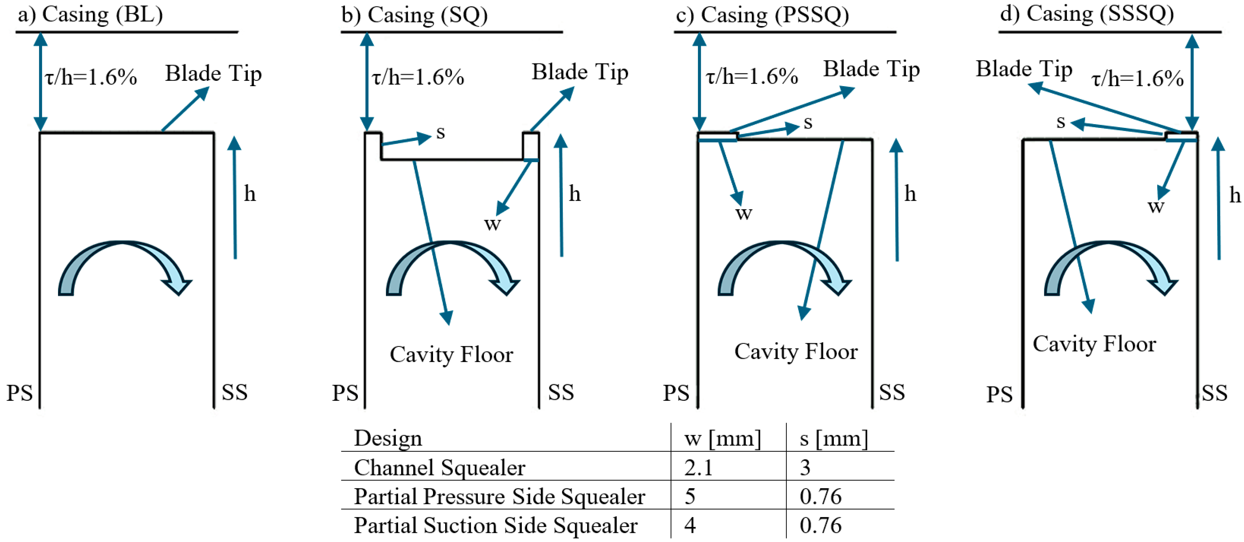
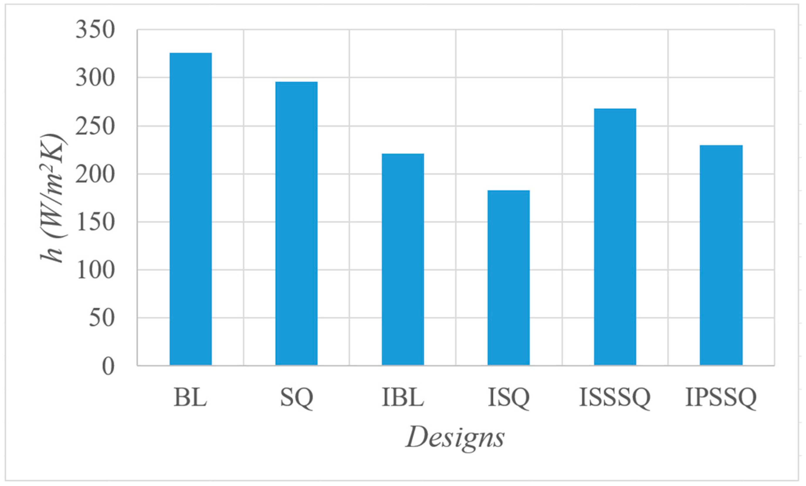
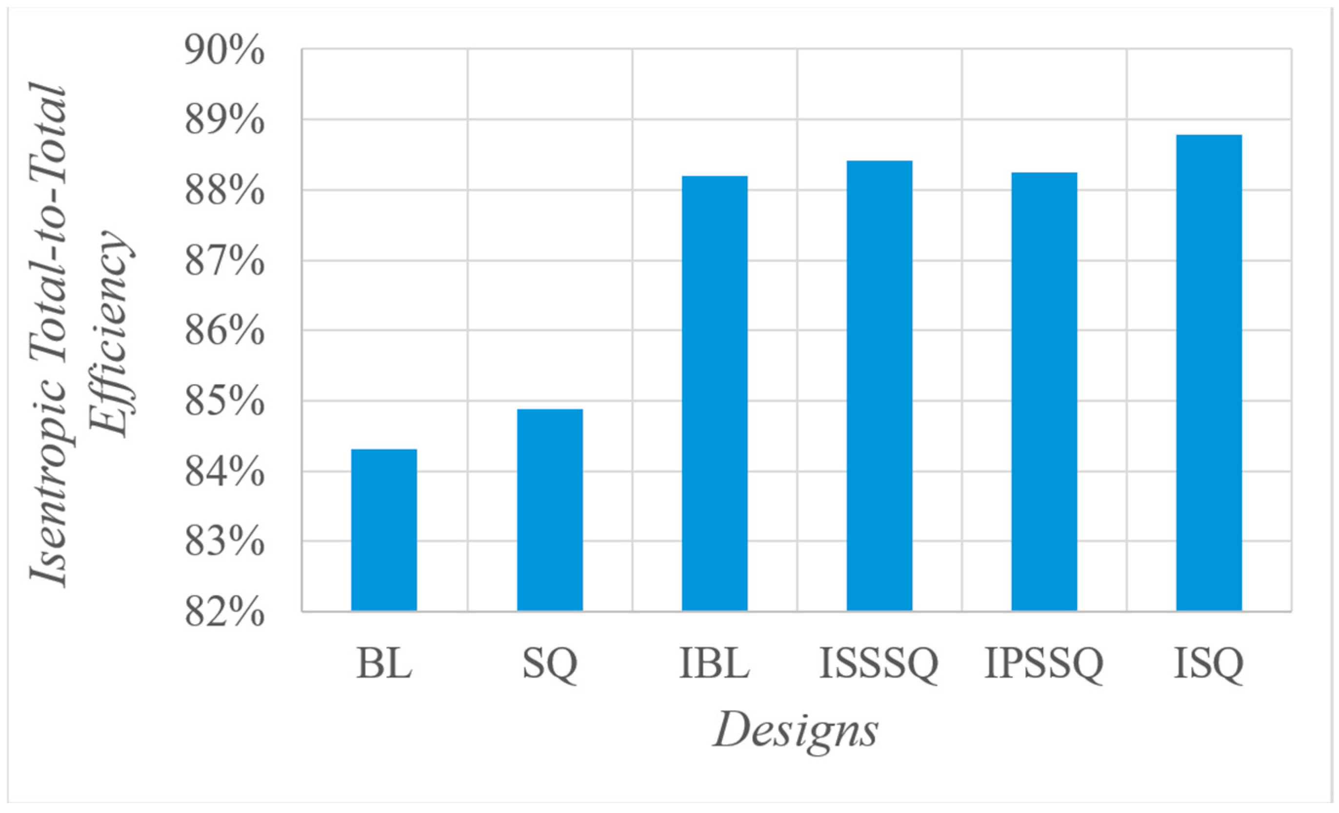
Table 6. ε, ϑ and Г show the normalized difference in total pressure loss coefficient, isentropic total-to-total efficiency and average heat transfer coefficient at blade tip, respectively, between baseline and related design. To create a clear image of the injection effect with recessed tips, channel squealer (SQ) results without injection are also provided. ISSSQ and IPSSQ stand for suction side and pressure side squealers plus injection, respectively. In comparison to the baseline, results show that the injection with a channel squealer tip (ISQ) achieves the best performance in all aspects, with a decrement of 2.87% and 4.91% in total pressure loss coefficient and tip
, respectively. Moreover, ISQ led to a 4.49% increase in isentropic total-to-total efficiency.
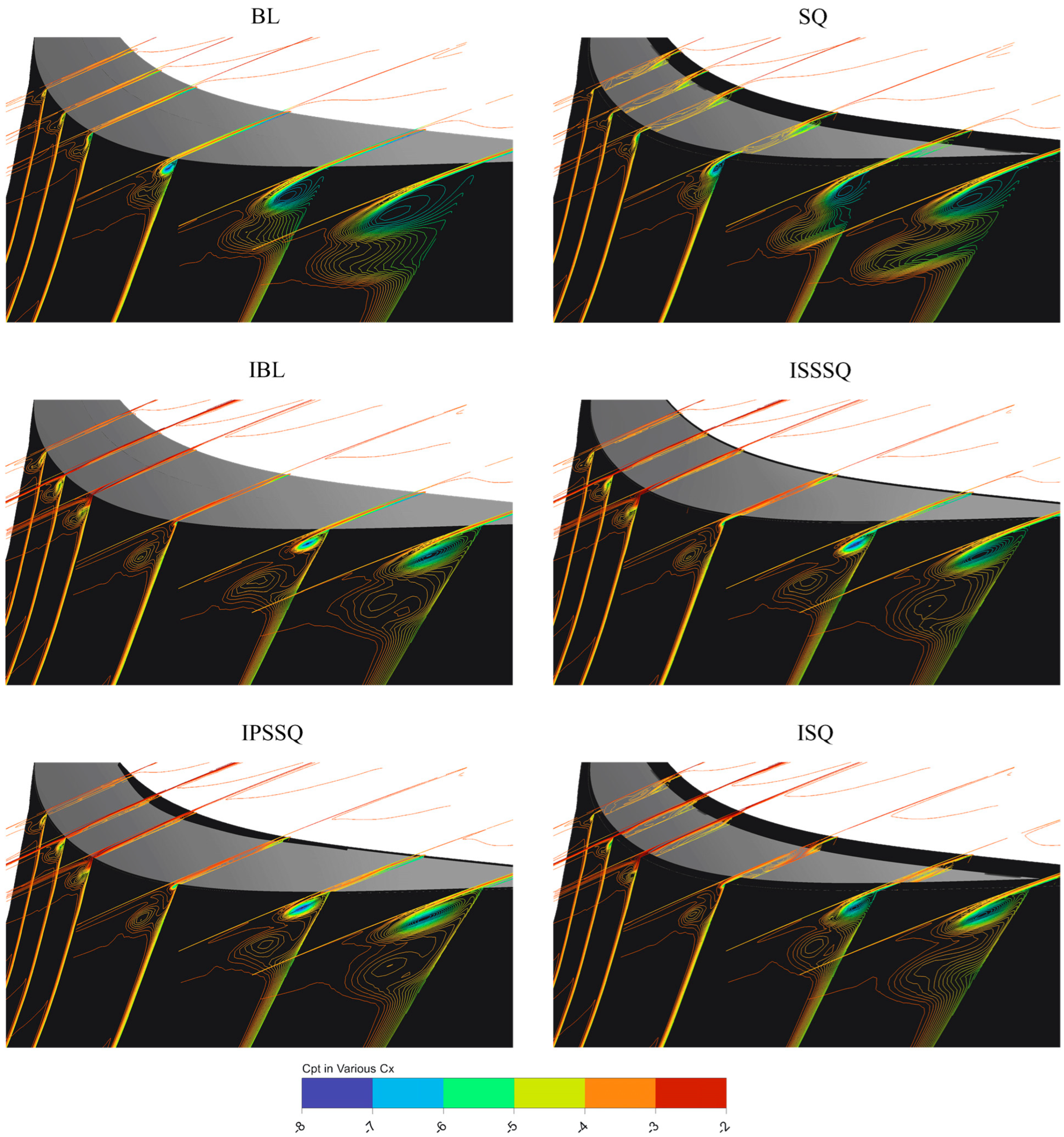
The total pressure coefficient of the designs in
Table 6 is shown in
Figure 11. The application of the channel squealer tip leads to a moderate reduction in the tip leakage vortex. Although other configurations also influence the vortex behavior, the most significant suppression is observed when the channel squealer tip is combined with casing injection.
Figure 12 provides insight into the aerodynamic impact of the observed phenomenon on the 0.05 C
x downstream of the blade. The baseline has the largest and most severe total pressure loss region at the tip. The SQ alone and the baseline with injection (IBL) design both notably shrink the tip loss zone relative to baseline.
The combination of injection plus SSSQ/PSSQ further reduces losses, and the injection plus channel squealer (ISQ) case nearly eliminates the high-loss core. Mid-span losses were low in the baseline and remained low in all modified cases. The ISQ design achieves the most uniform flow. The SSSQ plus injection (ISSSQ) case yields a very smooth profile with only a negligible tip deficit. PSSQ plus injection (IPSSQ) also improves uniformity significantly, though a slight tip deficit persists. The SQ-only and injection-only cases have moderate improvements, reducing the tip losses substantially, but not as completely as the combined ones.
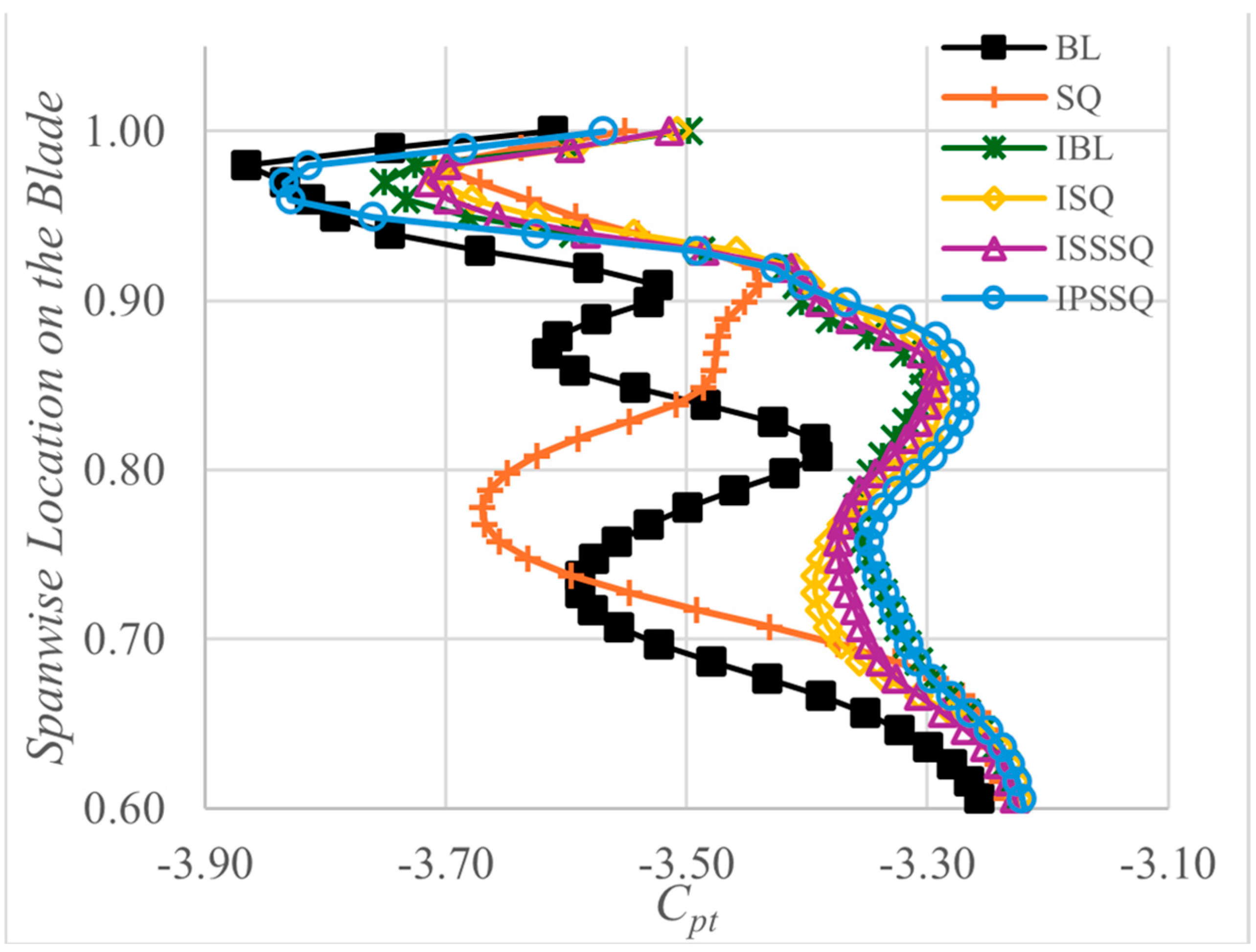
Distribution of mass averaged
Cpt values in the spanwise direction for all squealer designs and the baseline case is shown in
Figure 13. The BL and SQ cases exhibit the most significant pressure drop near the tip region above 70% span, reflecting intense tip leakage flow driven by the large pressure differential. In the SQ case, although the cavity rim partially blocks the tip gap, the lateral leakage paths remain active, sustaining the adverse pressure gradient and causing unsteady pressure oscillations close to the shroud. This is evident from the
Cpt values between 0.75 and 1.0 span in the current URANS results. The implementation of casing injection (IBL) markedly reduces the pressure drop near the flat tip. The injected flow forms a counter-jet opposing the leakage path, thereby redistributing local total pressure and suppressing the leakage vortex. This effect is further amplified in the ISQ case, where the combined barrier and jet create the most uniform
Cpt profile near the tip. Both ISSSQ and IPSSQ designs, featuring partial squealers, show intermediate performance; the pressure side squealer (IPSSQ) maintains a lower
Cpt near the shroud, suggesting suppression of the leakage from the pressure side, whereas the suction side configuration (ISSSQ) shows greater pressure retention in the 0.85–0.95 span range. Overall, designs incorporating full squealers with injection (ISQ) offer the most stable and elevated tip-region pressure distribution, directly correlating with minimized leakage driving forces.
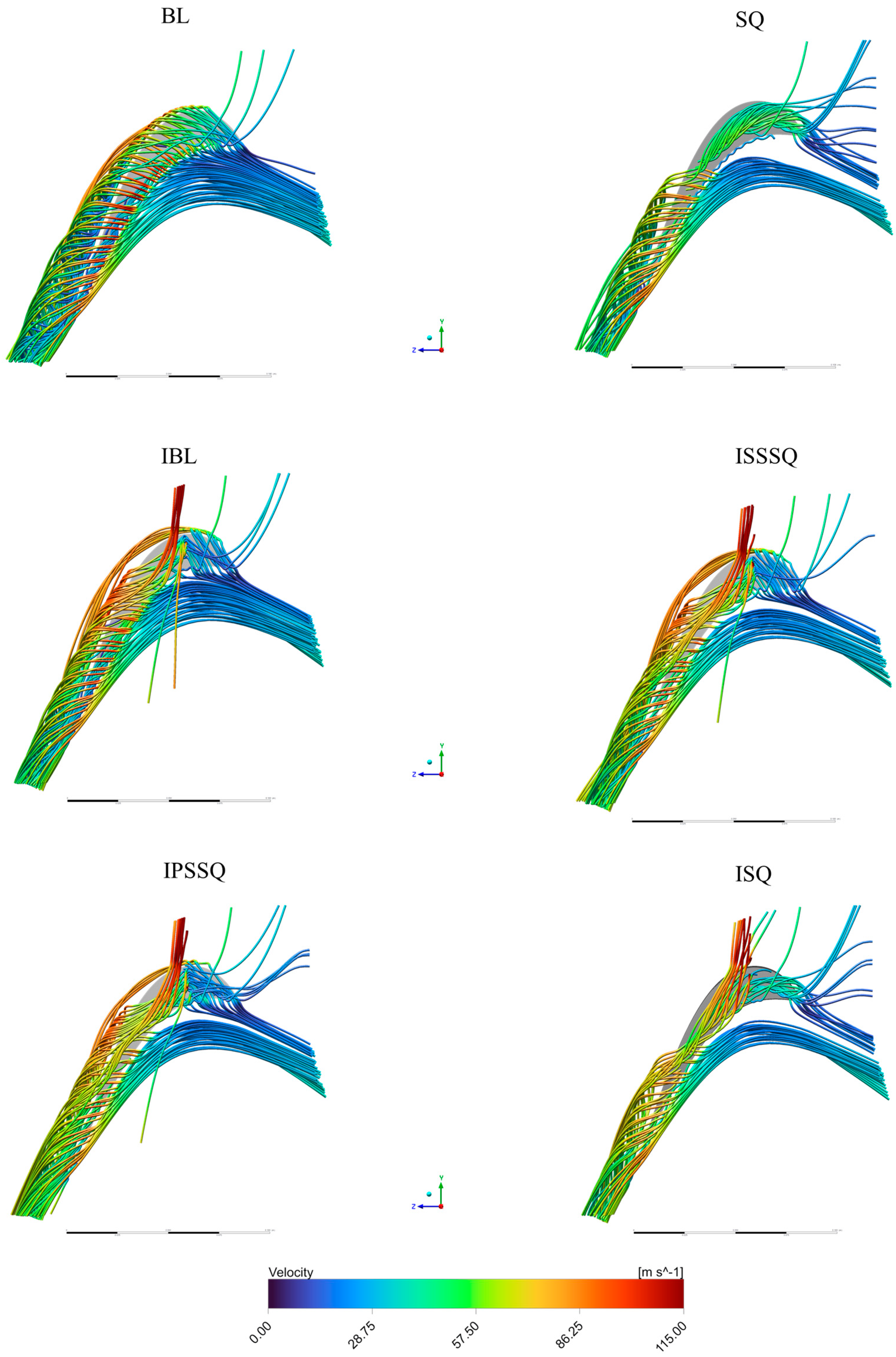
To observe the squealer and injection effects on the vortex mechanism and secondary flow structure, tip mid-gap streamlines are shown in
Figure 14. All streamlines color-coded with velocity magnitude are taken from the same surface with the same attributes for all designs. In the baseline tip design, the mid-gap flow shows a large, well-defined and strong tip leakage vortex (TLV) on the suction side. This high-pressure-to-low-pressure leak flow produces strongly curved streamlines bending toward the suction-side near the trailing edge, and a pronounced low-velocity core near the tip. Adding a full-width squealer rim markedly alters the tip leakage pattern. The flow into the tip cavity is evident; some streamlines recirculate within the cavity rather than spilling freely into the main flow. The strong TLV of the baseline is effectively suppressed, leading to weaker vortical structures downstream. In the SQ design, the suction-side streamlines are less curved in the free flow, and more fluid is contained in the cavity. In essence, the squealer’s cavity creates a localized recirculation zone that intercepts the leakage flow. In the IBL design, a vertical high-speed jet emerges from the suction-side tip, disrupting the normal leakage flow. This flow injection interference bends and distorts the streamlines near the tip; the jet injects momentum against the low-speed core of the TLV. As a result, the tip leakage vortex is partly broken up—the core of the vortex is less coherent downstream. The IBL design interferes with the TLV and shifts flow momentum, partially reducing leakage transport. Still, the tip vortex remains visible, and the flow blockage is only reduced relative to the baseline. Combining injection with a suction side partial squealer (ISSSQ) leads to a blockage of the primary leakage path at the suction side and further disturbance with the injection jet. The streamlines show hardly any strong TLV extending downstream; most leakage flow is confined near the tip. Almost no strong vortex is convected downstream; the tip flow is largely captured in the cavity or washed out by the jet. Mid-gap streamlines are much straighter, and the overall blockage is minimal.
With injection plus a partial squealer on the pressure side (IPSSQ), the effect on the TLV is intermediary. The pressure-side rim does not intercept the suction-side leakage flow, so the TLV remains substantial. At the mid-gap, a swirl region is seen on the suction side, indicating a moderately large vortex. The injection jet again interferes with flow, so the TLV core is somewhat disrupted. There is some additional mixing and curvature caused by the pressure-rim vortex, but the suction-side leak flow is not strongly suppressed. In summary, the IPSSQ design yields intermediate TLV reduction. The injection combined with a full squealer rim (ISQ) largely encloses the tip flow in a cavity on both sides. In this case, the suction-side rim still plays the dominant role in taming the TLV, and the injection jet further weakens any remaining leakage. The streamlines show a weak vortex; most flow is circulating within the enclosed cavity. The TLV is almost entirely confined and prevented from traveling downstream. The squealer cavity effects dominate here, and the strong jet momentum further prevents leakage outflow. The result is minimal flow blockage at mid-gap, with streamlines much less curved than baseline. Overall, the injection plus channel squealer produces a flow field with very little free leakage vortex, combining the benefits of a full rim and injected momentum.
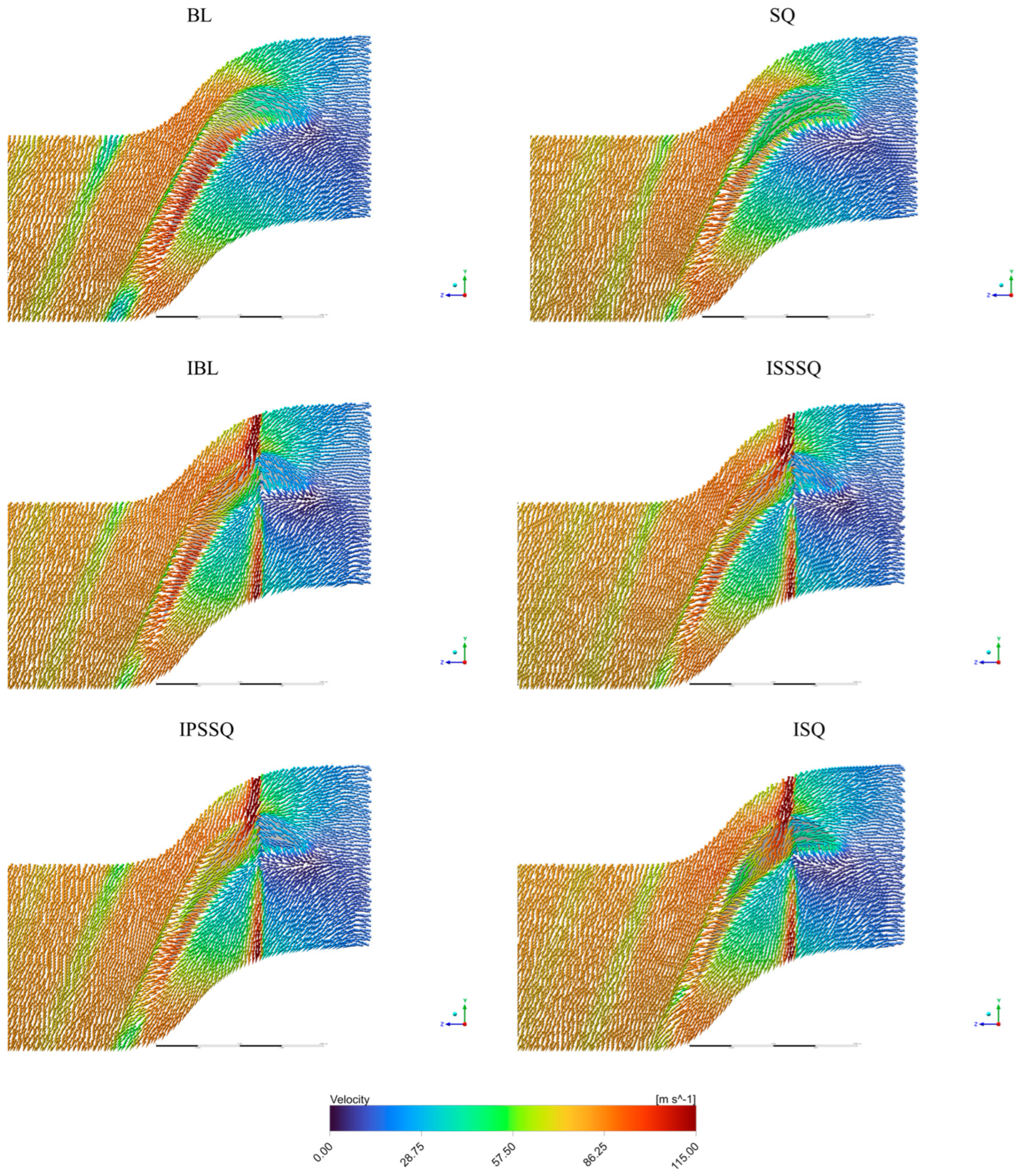
To further study these phenomena, mid-gap velocity vectors are shown in
Figure 15. The baseline case (BL) shows a large, coherent TLV rolling from the pressure side across the gap to the suction side. In the mid-gap plot, this appears as a swirling region spanning the gap, indicating strong low-speed recirculation. This TLV is long and energetic, inducing significant mixing and non-uniform downstream flow. Flow uniformity is poor with large reverse flow near the suction side.
At the channel squealer tip (SQ), the TLV still forms from the PS (pressure side) gap, but the vortex core is partly trapped in the tip channel. The mid-gap vectors show a narrower, weaker vortex than BL; the TLV is confined and somewhat displaced toward the cavity. Peak velocities in the gap are reduced, and downstream flow becomes more uniform. Overall, SQ weakens the TLV and lowers losses compared to BL, at the cost of introducing a channel vortex inside the cavity.
Adding an injection jet to the flat tip (IBL) dramatically alters the TLV. A high-momentum jet issues into the gap, acting like a momentum barrier that splits and weakens the TLV core. The TLV is forced to break up earlier and is less coherent. The mid-gap flow is dominated by this injection jet rather than a single vortex. As a result, the velocity field is more uniform: the strong recirculation on the suction side seen in BL is largely absent. Aerodynamic losses fall relative to BL because the injection suppresses leakage, although the jet itself creates localized high-speed shear at the tip. In short, this design shows a much weaker TLV and smoother passage flow than BL.
The suction-side squealer combined with injection (ISSSQ) provides strong TLV trapping. The TLV core is now nearly contained by the SS (suction side) cavity. The injection jet fills most of the gap, yielding a very uniform velocity field with minimal backflow. The TLV that does form is very compact and weak. Because the SS rib blocks the vortex exit, leakage flow is greatly reduced. A small, disturbed region near the SS is seen, but a smooth flow elsewhere. Overall, this design has much lower TLV strength and more uniform flow than BL at the expense of some concentrated vortex loss near the rib.
The pressure side squealer combination with injection (IPSSQ) captures the trailing-edge portion of the TLV, and the injection jet still impinges into the gap. The mid-gap vectors indicate the TLV is disturbed; the vortex near the PS side is fragmented by the rib, and the injection further drives flow into the tip gap. Flow is again more uniform than BL due to injections, and losses are reduced. In summary, the design shows moderate TLV suppression and improved uniformity, but without an SS rib, some leakage persists.
Combining a full channel squealer with injection (ISQ) yields the best TLV suppression and flow uniformity. The mid-gap plot for this design shows almost no coherent TLV core. The TLV is essentially broken up by the dual cavities and injections. The velocity field is highly even, with very little low-energy recirculation. This design produces the lowest aerodynamic losses; the leakage flow is minimized, and the passage flow is smooth. In short, this configuration shows the weakest TLV and most uniform outlet flow of all cases, indicating the best overall aerodynamic performance and TLV control.
3.2. Wall Shear Stress on the Investigated Designs
Figure 16 reveals how wall shear stress patterns reflect tip leakage vortex behavior, directly impacting aerodynamic losses. The baseline flat tip (BL) shows moderate-to-high shear over most of the tip, with a localized low-shear separation region on the suction-side near mid-chord. Computed equal shear stress lines similar to conventional oil flow visualizations reveal a coherent tip-leakage vortex originating near the pressure-side leading corner and sweeping across the tip to reattach on the suction-side. This strong TLV implies large mixing losses. In summary, BL has widespread shear on the tip, except at the separation line, and the vortex reattaches along the suction-side before the trailing edge.
The channel squealer tip dramatically alters the over-tip flow. The computed equal shear stress lines show a large low-shear region over much of the tip, with only a narrow high-shear band along the cavity rim. This indicates that much of the leakage flow is trapped inside the rim cavity. Equal shear stress lines show that a vortex still forms, but it is weaker and split; a suction-side cavity vortex and a pressure-side cavity vortex develop inside the rim. A portion of the flow recirculates in the cavity while the remaining leakage flows over the rim and exits toward the suction side. Because the cavity scrapes and dissipates leakage energy, the TLV leaving the squealer rim is weaker. As a result, SQ produces significantly lower leakage loss than BL. Overall, SQ concentrates shear near the rim edges and leaves the tip center largely separated, indicating effective TLV control and reduced loss.
The IBL tip disrupts the leakage vortex. The oil flow pattern is relatively uniform with a curtain effect at the injection location. Equal shear stress lines show that the coherent TLV is essentially broken up; instead of one strong swirl from PS to SS, the injection jet produces a vertical plume at the tip and disperses leakage flow. This delays and weakens vortex formation. The vortex trajectory is shifted upward, and the breakout point moves downstream. Consequently, TLV strength is reduced, and the mixing losses diminish. In this case, the flow from the injection holes appears to remain attached along the tip, with no large separation zone visible. Aerodynamic loss is lower than BL because of the weakened TLV.
The ISSSQ design’s oil flow map suggests an extensive low shear stress area. The equal shear stress lines show very low shear stress through the suction side, increasing smoothly around 70% of the axial chord. As a result, the tip leakage vortex is weaker in this design. The suction-side rim acts to trap flow locally; the TLV itself is carried to a downstream location compared to baseline. The leakage loss is much lower, but the flow does not reattach. It effectively skips over the tip. In short, this design shifts TLV downstream, yielding strong vortex control despite the rim.
The IPSSQ oil flow visualization shows moderate shear over the suction side, with a small high-shear region on the pressure side. Oil visualization, however, reveals a TLV with a strong red streak from the PS mid-chord edge to the SS. In other words, leakage still rolls up similarly to the ISSSQ design. The pressure-side rim slightly redirects part of the flow, and reattachment on the suction side occurs far upstream. Combining a full squealer rim with injection yields mixed results. The oil flow visualization again shows only small high-shear patches at the rim corners. The oil flow still contains a robust vortex along with evidence of the cavity swirl. The injection jet appears to block the tip leakage at the injection location, and the tip leakage vortex is delayed downstream, circulating within the cavity before exiting. Vortex breakdown may occur inside the cavity, raising some mixing losses, but the cavity trapping increases leakage path length.
3.5. Convective Heat Transfer on the Tip Surfaces of the Designs
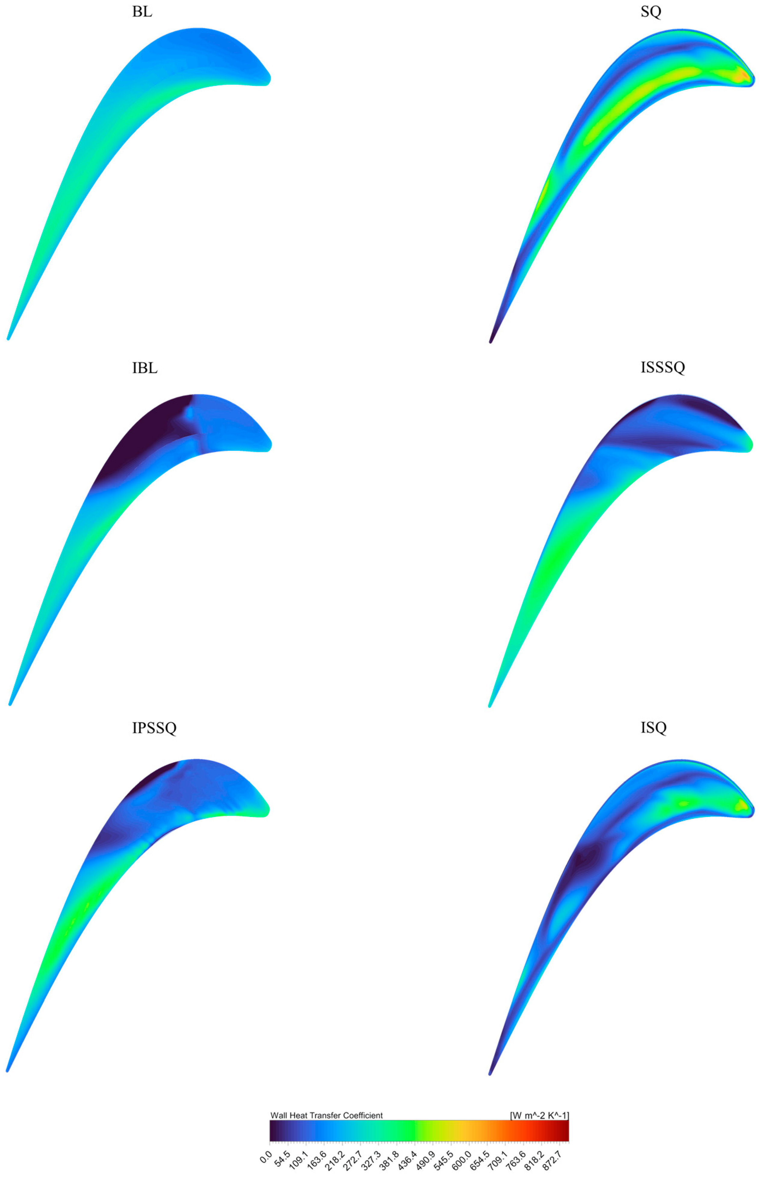
Figure 19 shows the contour plots of the local heat transfer coefficient (
h) of inspected tip designs. All the contours have been created with the same value range at the blade surface. The BL tip’s heat-transfer coefficient map is relatively uniform and moderate. The highest heat transfer occurs near the trailing edge suction side, where the main leakage flow vortex is present. In contrast, the leading-edge region on the pressure side shows lower
h because the flow there is weaker. Overall, BL has a smooth
h gradient with no extreme hotspots reflecting the relatively gentle shear and mild recirculation. The SQ tip’s
h distribution is notably higher in the pressure-side region than BL. The trapped recirculation drives high local shear, elevating local heat transfer.
In particular, the area near mid-chord on the pressure surface has a higher h compared to BL’s relatively uniform map. The leading edge has still lower h since little through-flow reaches it. Overall, the squealer tends to raise tip heat loads in local regions consistent with the idea that the large circulation enhances heat transfer in the cavity region. However, its total value is lower than BL since most of the blade surface has lower h values. The h distribution for IBL design is much lower than BL or SQ. Casing injection provides cooling, reducing tip surface temperature rise. Consistent with prior findings, relative casing motion significantly reduced the local heat transfer on the frontal tip region. In the map, the leading edge and much of the suction side have low h, with only a small region of mild h near the mid-chord. Essentially, the coolant flushes the tip, cutting heat transfer nearly in two-thirds relative to the no-injection case.
The h for ISSSQ is similar to IPSSQ and IBL, largely low with mild variation. Cavity concentrates heating on its floor, but injection cools most of the surface. There are no hot spots, but most of the blade surface after mid-chord has high h values as a result of the mixing of injection fluid with trapped recirculating vortex in the cavity. So, the average h has a higher value. The IPSSQ h map resembles the injection-only case, mostly low values with slight peaks near the trailing edge. The coolant still suppresses heat transfer broadly, but the partial rim may enhance it a bit under the rim ends. Compared to the injection-only design, any increase is minor. The result is a relatively low tip h overall, with only small high patches. The ISQ design’s h map remains much cooler than the no-injection squealer. The injected coolant significantly reduces surface h. The map shows mostly low h, with only a few mild patches. The rim cavity floor might still see a bit of heating since the flow circulates there, but it is much less than the hot spot in the SQ case. Thus, even though the flow is mostly intense, the presence of coolant keeps h lower overall.
