Abstract
Accurate trajectory tracking is crucial for fixed-wing unmanned aerial vehicles (UAVs) in executing diverse missions. However, the inherent strong nonlinearities, parametric uncertainties, and external disturbances in the UAV model present significant challenges for controller design. To address these challenges, this paper proposes a robust adaptive control strategy based on the backstepping technique. The proposed strategy effectively addresses a class of uncertainties with norm bounds that are unknown and state-dependent. An adaptive law is constructed to estimate the unknown parameters online, thereby enabling compensation for the effects of these uncertainties. Furthermore, to mitigate chattering, the controller is modified to generate smooth control inputs, ensuring that the steady-state tracking error is ultimately bounded and converges to an arbitrarily small neighborhood of zero. Simulation results demonstrate that, under realistic flight control sampling frequencies, the proposed controller achieves accurate trajectory tracking and eliminates the chattering phenomenon.
1. Introduction
Unmanned aerial vehicles (UAVs) have become indispensable tools for performing a wide range of complex missions, ranging from infrastructure inspection and environmental monitoring to search and rescue [1]. Fixed-wing UAVs are particularly well-suited for large-scale and long-endurance operations owing to their high aerodynamic efficiency and superior cruising capabilities. The successful execution of these missions fundamentally relies on the ability of the UAV to accurately follow a predefined route, which is typically specified as either a geometric path or a time-parameterized trajectory [2]. Accordingly, existing research has largely focused on two control paradigms: path following and trajectory tracking. Path following emphasizes spatial accuracy by keeping the vehicle close to a geometric route without strict timing constraints, whereas trajectory tracking requires adherence to a time-parameterized path, demanding synchronization of both position and velocity with a predefined schedule. In comparison, trajectory tracking control is generally more challenging than path following.
Current research on fixed-wing UAV path following predominantly employs simplified two- or three-dimensional (3D) kinematic models within a hierarchical control framework. This hierarchical architecture typically comprises two functionally distinct layers. The guidance layer generates geometrically constrained reference commands, such as desired airspeed, roll angle, flight path angle, and heading angle, for lower-level autopilots. Meanwhile, the control layer employs advanced algorithms to ensure robust tracking performance despite model uncertainties and external disturbances [3,4,5,6,7,8,9]. Numerous methods and their combinations have been developed to address the path-following problem for fixed-wing UAVs. These include vector field-based guidance design [3,9,10,11], disturbance observer-based methods [5,8,12,13], guidance law [14], optimal control strategies [5,15], nested saturation theory [6,7], sliding mode control [3,10,16], PID control [9], cascaded design [17] and feedback linearization [18], and model predictive control (MPC) [19]. A pertinent survey can be found in [20].
Compared to path following, trajectory tracking is essential for an increasing number of advanced missions where temporal precision is paramount. For example, in coordinated search and rescue (SAR) operations, multiple UAVs require precise temporal coordination to achieve systematic coverage without gaps or overlaps. Similarly, sensor-based missions, such as intelligence, surveillance, and reconnaissance (ISR) tasks, often necessitate timed arrivals at specific locations. Dynamic target tracking also depends on spatiotemporal synchronization. Long-endurance fixed-wing platforms like the Aerosonde UAV [21,22], frequently used for such SAR and ISR missions, serve as a relevant archetype where precise trajectory tracking is crucial. Under these dynamic conditions, UAVs must do more than merely follow a fixed geometric route—they need to execute precise, time-parameterized trajectories to meet stringent temporal constraints. In contrast, conventional path-following strategies are insufficient, as they neglect the temporal dimension of task execution. Furthermore, a typical fixed-wing UAV is an underactuated system with six degrees of freedom (position and orientation) and four independent control inputs (throttle and three control surfaces). In real-world operations, UAVs must often contend with harsh environmental conditions, including strong winds and gusty weather. These factors introduce additional challenges to the trajectory tracking problem. Therefore, developing robust and accurate trajectory tracking methods for UAVs under adverse conditions is both necessary and highly significant. However, current research on trajectory tracking primarily focuses on quadrotor UAVs [23,24,25], vertical take-off and landing (VTOL) UAVs [26,27], tilt-rotor UAVs [28], helicopters [29,30], and missiles [31,32], which require precise and timely trajectory monitoring during specific flight phases such as take-off, landing, and hovering [33]. In contrast, studies directly targeting fixed-wing UAVs remain relatively limited.
Ren et al. [34] designed a trajectory tracking controller for UAVs using the control Lyapunov function method, considering velocity and heading rate constraints based on a simplified UAV kinematic model. This work was further extended in [35] by adopting a more accurate kinematic model that explicitly takes into account first-order autopilot responses to air speed and roll commands. Rao et al. [36] transformed the aircraft perching problem into a trajectory tracking problem and designed a sliding-mode controller to compensate for perturbations. Brezoescu et al. [37] designed a path-following controller for small aircraft flying in unknown crosswind conditions using an adaptive backstepping approach. However, their study was limited to planar guidance based on a kinematic model and did not account for other uncertainties beyond crosswind effects. Grymin et al. [38] developed a dynamic feasible reference trajectory based on an identified aerodynamic model of the UAV and designed a discrete feedback controller for reference trajectory tracking. In [39], an MPC-based approach was employed at the guidance level to design the guidance law, while at the lower control level, an adaptive backstepping method was used to design the control law. Li et al. [40] investigated fixed-wing aircraft tracking control during payload drops, modeling the system as a switched system to handle trajectory trim point variations and mass changes. A switched MPC-based feedback control law is designed to follow a 3D Dubins trajectory. Xu et al. [41] achieved finite-time trajectory tracking for fixed-wing UAVs by transforming the outer-loop position dynamics into a double-integrator system and employing disturbance observers to estimate unknown external disturbances. A second-order compensation function observer-based model compensation control algorithm was designed for a fixed-wing UAV [42]. However, their methodology relies on assumptions that the lumped uncertainties are bounded and continuously differentiable. Zhao et al. [43] developed a predefined-time trajectory tracking controller based on a simplified fixed-wing UAV model. However, their approach neglected the aerodynamic characteristics and relied on the assumption that the second derivatives of total disturbances are bounded by known constants.
To address the underactuated nature of fixed-wing UAVs, a cascade control architecture is frequently adopted for trajectory tracking. In this well-established framework, the outer-loop position controller generates desired thrust and attitude references for the inner-loop attitude controller to follow. Within such architectures, various robust and adaptive techniques have been developed to enhance performance against lumped system uncertainties. Based on robust signal compensation [44] and feedback linearization techniques, Zhang et al. [45] and Yang et al. [46] designed a robust finite-time trajectory tracking control scheme and a robust trajectory tracking controller in the horizontal plane, respectively, for simplified aerodynamic models. Extending the work in [46], Yang et al. [47] modeled the UAV dynamics using a more general aerodynamic model and designed a robust cascaded horizontal plane trajectory tracking controller. This approach was further extended to 3D trajectory tracking in [48]. In the studies [45,46,47], the proposed control schemes relied on the assumption that the bound parameters of the lumped uncertainty are known. This condition was relaxed in [48], where a robust adaptive trajectory tracking control scheme was proposed, using adaptive techniques to estimate the unknown parameters of the norm bounds online. The effectiveness of these approaches has been validated through hardware-in-the-loop simulations or flight tests.
In the aforementioned studies, similar to research on path following, most designs rely solely on high-level car-like kinematic models without further considering the aerodynamic characteristics and inherent operational mechanisms of the aircraft [34,35,37]. However, these aspects are precisely what distinguish fixed-wing UAVs from general nonlinear systems and represent the primary challenges in controller design. Moreover, studies that account for uncertainties and external wind disturbances often impose assumptions [39], such as requiring the lumped uncertainty to be continuously differentiable [41,42] or both the uncertainty itself and its second derivative to be bounded by known constants [43]. These assumptions are somewhat restrictive and may limit applicability to real-world fixed-wing UAV scenarios.
Inspired by the aforementioned observations, this paper aims to develop a robust adaptive trajectory tracking control scheme for fixed-wing UAVs with uncertainties. The proposed controller is designed to achieve precise tracking of pre-planned trajectories under challenging external conditions. It also accounts for parametric uncertainties in the UAV model. The controller is designed using the backstepping technique, which methodologically creates a cascaded structure composed of a kinematic loop and a dynamic loop. The kinematic loop computes a desired velocity vector based on the position error, which is then tracked by the dynamic loop. The dynamic loop, comprising a nominal controller and a robust compensation controller, calculates the final commands to ensure accurate trajectory tracking. In addition, a critical challenge in fixed-wing UAV motion control lies in handling uncertainties, whose norm bound parameters are typically unknown. Some existing methods, like [43,45,47], require known bound constants. To overcome this limitation, this paper introduces a robust adaptive approach to deal with uncertainties. Finally, to mitigate chattering, a practical robust adaptive tracking controller incorporating boundary layer techniques [49] is developed. All proposed designs are rigorously analyzed.
The main contributions of this paper are summarized as follows:
- A robust adaptive control strategy is proposed using the backstepping technique for fixed-wing UAVs subject to uncertainties with unknown state-dependent norm bounds and parameters. Adaptive laws are designed to estimate these norms and parameters online, enabling effective compensation for the effects of uncertainties. Unlike many existing studies that rely on known uncertainty bounds or assume continuous differentiability of uncertainties (e.g., [42,43,45,47]), the proposed method operates under more general assumptions, thus enhancing its practicality. Moreover, to mitigate chattering effects, the controller is refined to ensure smooth control inputs while guaranteeing that the steady-state tracking error is ultimately bounded and converges to an arbitrarily small neighborhood of zero.
- A cascaded control architecture is designed based on the kinematic/dynamic decomposition of a fixed-wing UAV point-mass model. This architecture serves as a crucial intermediate layer that converts trajectory commands generated by high-level planners using simplified kinematic models into the bank angle and angle-of-attack commands required by the low-level attitude controller. By internalizing the UAV’s essential trajectory dynamics, the proposed approach not only ensures precise trajectory tracking but also achieves two key advantages: (1) it reduces the dependency of the high-level trajectory planning algorithm on the detailed complex plant model, thereby decreasing design complexity; and (2) it supplies the low-level attitude controller with dynamically feasible commands.
- A design paradigm integrating structured uncertainty modeling with direct nonlinear control is proposed. Unlike conventional approaches prevalent in prior literature, which often depend on feedback linearization coupled with lumped uncertainty suppression (e.g., [45,46,47,48]), the proposed method first constructs norm-bounded uncertainty descriptions based on physical principles (e.g., correlating aerodynamic uncertainty bounds with the square of airspeed). This refined, state-dependent uncertainty model is then leveraged to synthesize a robust adaptive controller via backstepping directly for the original nonlinear system. This direct design approach, which obviates the need for model linearization, enables targeted online compensation for different classes of uncertainties, thereby reducing the conservatism of the control law.
The remainder of this paper is organized as follows. Section 2 presents the dynamic model of the fixed-wing UAV along with a detailed problem formulation. Section 3 designs the robust adaptive tracking controller, which is further refined into a practical controller in Section 4. Section 5 presents numerical simulation results. Finally, Section 6 concludes the paper.
2. Problem Formulation
This section begins by introducing the notations and essential concepts. Then, a detailed problem formulation is provided.
Throughout this paper, let denote the Euclidean norm. Let denote the identity matrix of appropriate dimensions, and represent a diagonal matrix. represents the minimum eigenvalue of matrix . For simplicity, the time variable t will be used flexibly when referring to time-varying signals. In some instances, t may be omitted for brevity. Figure 1 provides a schematic illustration of the SAR mission scenario. As depicted in the figure, the inertial frame is defined with its axes corresponding to the East, North, and Up directions. The velocity vector , velocity elevation angle , and velocity heading angle are also annotated in accordance with standard aerial vehicle kinematics.

Figure 1.
Schematic diagram illustrating a Search and Rescue (SAR) mission scenario conducted over a maritime environment. The pre-planned, lawnmower-pattern search trajectory is depicted as a yellow solid line. The inertial coordinate frame is , with its axes corresponding to the East, North, and Up directions. , , and represent the velocity vector, velocity elevation angle, and velocity heading angle, respectively.
This paper adopts a 3D point-mass model for the UAV, building on prior work [21,50,51,52,53]. The model incorporates both uncertainties and external disturbances. It is important to note that the model assumes zero sideslip (i.e., sufficient control power exists that all maneuvers are coordinated [48,50,52]). Under the assumption of a flat and non-rotating Earth, the UAV’s dynamics are described by the following equations:
where is the angle of attack (AOA), m is the mass, g is the acceleration due to gravity, T is the thrust, L is the lift, D is the drag, is the bank angle, denotes the position vector in the inertial frame, and represents the external disturbance. For notational convenience, define .
As versatile platforms, UAVs are equipped with different payloads depending on mission requirements, such as reconnaissance sensors, communication relays, or cargo. The different mass of these payloads leads to changes in the total mass m for each flight. To address this parametric uncertainty in the controller design, the mass of the UAV is modeled as:
where represents the precisely known nominal mass (e.g., the empty weight of the UAV), and denotes the uncertain part, which encapsulates all mass deviations arising from physical factors such as payload variations.
The aerodynamic lift L and drag D of the UAV are given by
where is the atmospheric density, S is the aerodynamic reference area, and are the lift and drag coefficients, is the coefficient at zero AOA, is the lift curve slope, is the zero-lift drag coefficient, e is the Oswald efficiency factor, and AR is the wing aspect ratio.
The model presented in (3) is adopted as the nominal model in this work. To account for uncertainties in aerodynamic parameters, the actual forces L and D are decomposed into nominal components (denoted by subscript o) and uncertain components (denoted by subscript R):
The nominal components, and , are thus computed using the model in (3), with their parameters determined through wind tunnel experiments or similar methods. The uncertain components, and , capture deviations from the nominal values due to interpolation errors or other factors.
The thrust T, AOA , and bank angle are selected as the control inputs for the UAV dynamics described in Equation (1).
Let denote the preplanned reference trajectory. The control objective of this study is to design a robust adaptive trajectory tracking controller for the system described by Equation (1), such that or , where is a given positive constant.
3. Trajectory Tracking Control
To address the nonlinear and coupled dynamics of the UAV described in (1), this paper proposes a controller based on the backstepping technique to solve the trajectory tracking problem. This controller is designed to generate the necessary commands () required for trajectory tracking, which would typically be sent to a lower-level attitude control system (autopilot) in a complete hierarchical architecture.
Methodologically, the backstepping design process itself organizes the proposed controller into a cascaded structure. This structure comprises two main parts derived from the backstepping steps:
- (1)
- A kinematic loop: This part computes a desired velocity vector (i.e., virtual control law , which is essentially defined by the velocity magnitude , the velocity elevation angle , and the velocity heading angle ) based on the position tracking error.
- (2)
- A dynamic loop: This part ensures the UAV’s actual velocity vector tracks the desired velocity vector generated by the kinematic loop, calculating the final commands () while compensating for the UAV’s dynamics and uncertainties.
This design approach effectively decouples the kinematic and dynamic aspects within the trajectory tracking controller itself. The overall control framework is illustrated in Figure 2. Before proceeding with the detailed design, the necessary assumptions are introduced.

Figure 2.
Block diagram of the overall hierarchical control architecture. The components and signals shown with solid lines represent the control law and simulation loop implemented in this paper, where the UAV dynamics (point-mass model) is directly driven by T, , and . The dashed components illustrate how the proposed controller would integrate with a conventional inner-loop attitude controller (autopilot) in a real-world application.
Assumption 1.
The reference trajectory and its first and second derivatives are piecewise uniformly bounded.
Assumption 2.
The external disturbance is bounded in norm, satisfying where is a nonnegative unknown constant.
Assumption 3.
The mass uncertainty satisfies , where is a nonnegative unknown constant.
Assumption 4.
There exist unknown positive constants and such that the aerodynamic uncertainties satisfy and .
Remark 1.
The choice of an uncertainty bound proportional to in Assumption 4 is physically motivated. Aerodynamic forces (lift and drag) are primarily driven by the dynamic pressure term . While the aerodynamic coefficients (, ) themselves can exhibit some dependence on airspeed, the variation due to is typically the dominant factor within standard operational flight envelopes. By assuming the upper bounds for the uncertainties and scale with , we capture this principal effect, lumping residual dependencies and other unmodeled factors into the unknown constants and . This structured uncertainty modeling is a reasonable practice for the flight regime considered in this study, characterized by moderate AOA and speeds where significant compressibility or coefficient scaling effects are not dominant.
The design process starts with the first step of the backstepping procedure, which forms the kinematic loop of the controller.
Step 1: Define the position tracking error as . From the subsystem (1a)–(1c), it follows that
where . To apply backstepping, is regarded as the virtual control. A stabilizing function is then designed, which represents the desired value of the virtual control and is denoted as .
is designed as follows:
where is a positive definite diagonal matrix.
Choose
as a Lyapunov function candidate. The derivative of along the solution of Equation (5) yields
which means that the state of the error system at the origin, , is asymptotically stable.
Step 2: Let be the deviation of from its desired value :
For brevity, the following notations are introduced:
Then the dynamics of the error variable , as described in Equations (11)–(13), along with Equation (10), can be reformulated as:
For a given , the actual control inputs T, , and can be obtained by solving equations:
where and denote the nominal aerodynamic forces computed as functions of according to (3), and the transcendental Equation (15b) with respect to can be solved numerically. The Newton–Raphson method is well-suited for this purpose, as its quadratic convergence rate and high computational efficiency make it particularly appropriate for real-time implementation onboard the fixed-wing UAV.
Next, focus on the design of the control law . Based on robust compensation theory, the proposed control law comprises two components:
where is the nominal control input, designed for the nominal system derived from Equation (14), and is the robust compensating input, intended to restrain the effects of uncertainties and external disturbances.
The nominal controller is designed as:
where is a constant, and . Denote . Substituting Equation (17) into Equation (14) yields:
Choose
as a Lyapunov function candidate for the full error system in the coordinates. The derivative of along the solutions of (10) and (18) is computed as
Under Assumptions 1–4, the following bounds hold:
where are all positive constants. Denote and . By substituting Equation (21) into Equation (20), the following result can be derived:
The corresponding robust compensating controller is given by
where , and are the corresponding estimated parameters about . Let . Substituting Equation (23) into Equation (22) yields:
To further design the update law, the Lyapunov function candidate is augmented with a quadratic term of the parameter error :
where are the adaptation gains. Based on Equations (20) and (24), the derivative of satisfies
Thus, one can choose the update law
which yields
From Equation (28), it can be inferred that , , and are bounded. Based on Equations (10) and (14), it further follows that and are also bounded. Therefore, and are uniformly continuous. Moreover, from Equation (28), the following inequality holds:
which implies that both and are bounded. Hence, by applying Barbalat’s lemma, it can be concluded that and , which consequently leads to .
The above design and analysis of the robust adaptive controller culminate in the following theorem.
Theorem 1.
Consider the UAV model described by Equation (1), with its mass given by Equation (2), and aerodynamic forces represented by Equations (3) and (4). Suppose that Assumptions 1–4 hold. The actual control inputs T, α, and ϕ are determined by Equations (15)–(17), (23), and (27). Then, for any bounded initial states and , the trajectory tracking error asymptotically converges to zero, that is, , and all involved states remain bounded.
Remark 2.
It should be pointed out that Theorem 1 demonstrates that all states, including the estimated parameters, remain bounded and that the tracking error converges asymptotically to zero. However, the convergence of the estimated parameters to fixed values is not guaranteed. Furthermore, the control law given in Equation (23) may induce chattering. To improve the practicality of the controller, the following section introduces a modified design method to address both parameter drift and chattering.
4. Practical Robust Adaptive Trajectory Tracking Control
The control law given by Equation (23) is a discontinuous function. This characteristic can result in undesirable chattering effects. Here, inspired by the approach proposed in [49] to address the discontinuity in sliding mode control laws, the proposed control law (23) is modified as follows:
with the modified update law:
where is a small positive constant, and are positive constants.
Remark 3.
The damping terms in the modified update law (31) are essential. As pointed out in [49], without the damping terms, the estimated parameters may tend to grow unbounded in practical applications. Under the revised control law, the closed-loop system loses global asymptotic stability, and the tracking error no longer converges to zero but instead converges to a neighborhood of zero. In practical implementations, it is generally not necessary for the tracking error to converge precisely to zero, but the smoothness of the controller is often a requirement. The modified control law satisfies this criterion and is therefore referred to as a practical robust adaptive control law.
To verify the effectiveness of the modified control law and determine the boundary of the convergence region, defined in Equation (25) is used as the Lyapunov function candidate. Differentiating with respect to time yields:
The subsequent analysis considers two distinct cases.
- (I)
- If .
In this case, according to Equation (30), . Substituting it along with Equation (31) into results in:
- (II)
- If .
In this case, from Equation (30), one has . Following a similar approach as in (I), the result of is obtained as
When , the term in Equation (36) reaches the maximum value of . Thus, one finds that
Equation (32) can be further written as
where and remain consistent with those in case (I).
Considering both cases (I) and (II), it can be concluded that satisfies the following inequality
where . It follows from the Comparison Lemma that an upper bound for can be established as:
By defining and noting that the exponential term decays to zero as (since ), the limit of satisfies
which means that the error states are guaranteed to converge to and remain within the compact set
Thus, constitutes an ultimate bound set for the error states. Furthermore, on the boundary one has , the set is therefore positively invariant.
Based on this analysis, all error states are proven to be ultimately bounded.
Next, according to Equation (25), one has that
Define . One can deduce that
By selecting sufficiently small values for and , a sufficiently small can be obtained. This, in turn, leads to a sufficiently small , which allows the ultimate upper bound of the error states in Equation (44) to be made arbitrarily small.
Remark 4.
A practical note on selecting the parameters δ and introduced in this section is warranted. The boundary layer width δ in Equation (30) controls the trade-off between control signal smoothness and the ultimate bound of the tracking error; a larger δ yields smoother control but potentially larger steady-state error. The coefficients in Equation (31) provide robustness against parameter drift by introducing damping into the adaptation law; larger values offer stronger protection against drift but might slightly slow down adaptation or introduce bias. In practice, both δ and the set of values are typically determined through simulation-based tuning. The goal is to find appropriate values that achieve acceptable control smoothness and ensure parameter convergence under representative operating conditions, while keeping the tracking error within performance specifications.
The analysis presented above culminates in the following theorem.
Theorem 2.
Consider the UAV model described by Equation (1), with its mass given by Equation (2), and aerodynamic forces represented by Equations (3) and (4). Suppose that Assumptions 1–4 hold. The actual control inputs T, α, and ϕ are determined by Equations (15)–(17), (30), and (31). Then, for any bounded initial states and , the trajectory tracking error is ultimately bounded with the ultimate bound given by Equation (44) and exponentially converges to the arbitrarily small region .
5. Simulation Studies
To validate the effectiveness of the proposed robust adaptive control strategy, numerical simulations are conducted. The tracking performance of the controller is evaluated using a reference trajectory designed for a Search and Rescue (SAR) mission.
5.1. Simulation Setup and Scenario Configuration
- (I)
- Fixed-wing UAV platform specification
To provide a concrete case study for the general control law developed in this paper, the simulation is based on the parameters of the Aerosonde UAV, a well-known long-endurance platform suitable for missions like SAR. The key parameters of its model are adopted from [21,22] and summarized in Table 1.

Table 1.
Parameters of the fixed-wing UAV model [21,22].
- (II)
- Modeling of system uncertainties and disturbances
In this study, the system uncertainties refer to certain physical parameters of the UAV model, specifically, , , and in Equations (2) and (4). These terms account for practical deviations arising from different flight conditions, or variations in payload during SAR operations. These parameters are assumed to vary within a bounded uncertainty range of up to of their nominal values:
where , are independent constants.
External disturbances, particularly environmental wind, alter the relative airspeed, thereby modifying the aerodynamic forces and moments, and ultimately influencing the UAV’s motion states. To facilitate the simulation of a UAV performing an SAR mission in a realistic wind field, a composite external wind disturbance model was developed based on [54]. This model decomposes the total disturbance into a linear superposition of a quasi-steady bias, and a time-varying component, which is given by
where the constant term represents the mean wind, and the sum of sinusoids represents persistent, time-varying wind disturbance components with multiple frequency contents. The set values of the relevant parameters can be referred to Table 2.

Table 2.
Parameters of the external disturbance .
It should be noted that these parameters were methodically synthesized based on the model structure in [54] to create a challenging yet realistic simulation scenario that includes both mean wind and persistent wind variations. Figure 3 provides a visual representation of the time histories of these disturbance components. The objective was to evaluate the robustness and tracking performance of our proposed controller under such adverse conditions.
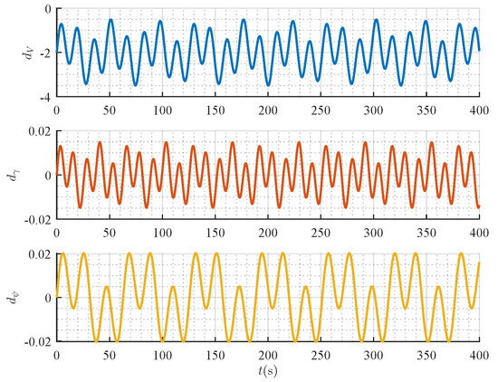
Figure 3.
The external disturbance components ().
- (III)
- SAR-specific reference trajectory generation
This part presents a 3D trajectory optimized for SAR operations. The trajectory architecture implements a parallel-line scanning pattern (commonly termed “lawnmower” configuration), which is widely adopted in SAR due to its efficiency in systematically covering large regions with minimal overlap and blind spots. This pattern is particularly effective when the target location is uncertain and uniformly distributed.
As shown in Figure 4, the reference trajectory follows a lawnmower pattern within a designated rectangular search area spanning 1400 m in length and 700 m in width. The trajectory geometry consists of segments with two different turning radii: the initial loop features 350 m-radius circular arcs connecting the 1400 m straight legs, while the subsequent loops utilize tighter, 245 m-radius circular arcs for the turns, maintaining the same straight segment length.
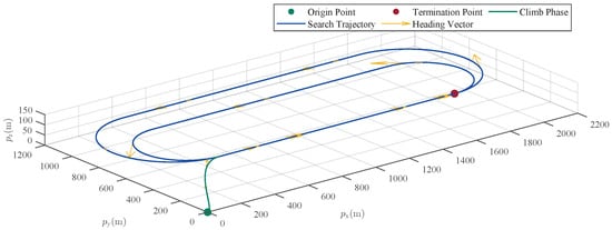
Figure 4.
3D trajectory for SAR operations.
The UAV initiates its flight from the origin point at coordinates . To transition smoothly into the search phase, a Bézier curve is planned as a pre-entry trajectory, guiding the UAV to the search entry point . This transition phase takes approximately , during which the UAV gradually accelerates and adjusts its heading to ensure it reaches the entry point with a constant airspeed of 35 m/s.
After entering the search region, the UAV follows a predefined multi-loop lawnmower pattern. It first executes one complete loop consisting of 1400 m straight-line sweeps connected by 350 m-radius circular arcs for turning at the boundaries. Immediately following this initial loop, the UAV performs one additional, consecutive loop along the same straight path alignment but utilizing tighter, 245 m-radius circular arcs for the turns. Throughout the entire search process, encompassing all loops, the UAV maintains a constant cruise speed of 35 m/s and a fixed altitude of 100 m, ensuring stable flight dynamics and consistent sensor performance. The 2D projection of the search trajectory is presented in Figure 5, while Figure 6 illustrates the velocity magnitude together with its three-axis components, and Figure 7 depicts the reference angles.
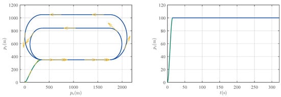
Figure 5.
2D projection of the search trajectory.

Figure 6.
Velocity of the search trajectory and its three-axis components.
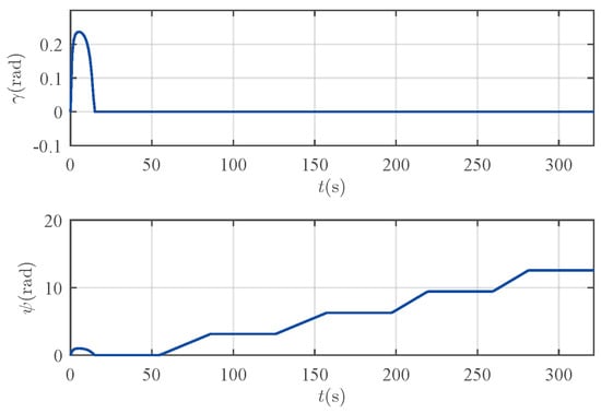
Figure 7.
Reference angles of the search trajectory.
5.2. Performance and Robustness Validation
This subsection aims to validate the core performance of the proposed control law. The simulation results presented here will demonstrate the controller’s ability to achieve trajectory tracking in the presence of significant parametric uncertainties and external wind disturbances.
For convenience, the following abbreviations are hereafter used: NC denotes the nominal controller, RAC the robust adaptive controller, O-RAC the original robust adaptive controller (designed in Section 3), and P-RAC the practical robust adaptive controller (designed in Section 4).
The initial conditions and key parameters are specified as follows. The UAV is initialized with the state . The controller gain is set as with . For O-RAC, the adaptive gain vector is defined as . For P-RAC, the adaptive gain vector and the damping coefficient were selected as and , respectively, with the boundary layer width set to . The Simulink solver is configured with a fixed step size of .
The simulation results are presented in Figure 8, Figure 9, Figure 10, Figure 11, Figure 12, Figure 13 and Figure 14. Figure 8 illustrates the 3D tracking trajectories of the UAV under the three controllers. Since the tracking error in Figure 10 is negligible compared to the scale of the entire flight trajectory (on the order of hundreds of meters), all three control laws, from a macroscopic perspective, enable the UAV to track the reference trajectory. This is visually confirmed by the nearly imperceptible trajectory deviations in Figure 8 and the match between the UAV’s actual and reference states in Figure 9.
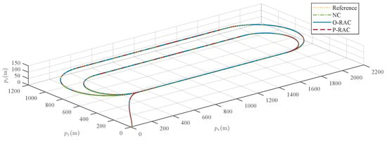
Figure 8.
Comparison of the reference and actual flight trajectories.
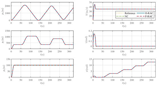
Figure 9.
Comparison of reference and actual states.
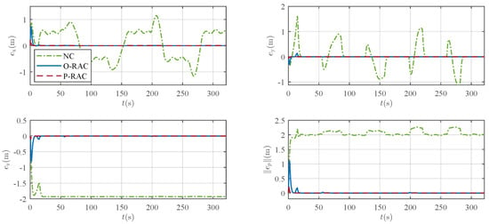
Figure 10.
Comparison of Tracking errors and their three-axis components under different control laws.
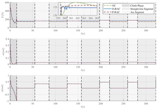
Figure 11.
Comparison of control signals under three different control laws.
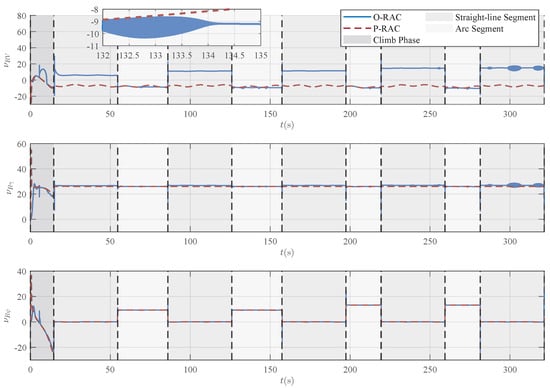
Figure 12.
Comparison of robust compensation signals under two robust adaptive laws.
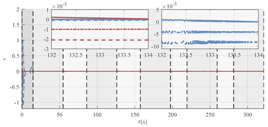
Figure 13.
Comparison of the deviations of the virtual control inputs under two robust adaptive laws (blue lines: O-RAC; red lines: P-RAC).
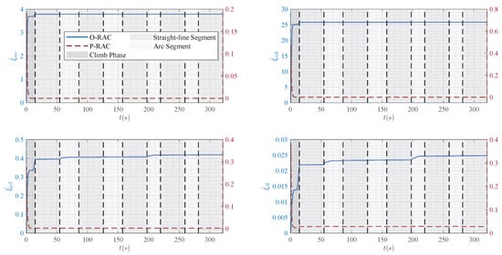
Figure 14.
Comparison of the estimated parameters under two robust adaptive laws.
A detailed examination of the tracking error in Figure 10 reveals that the controllers exhibit significant differences in performance. The tracking under NC exhibits a relatively pronounced error, with a peak value exceeding 2 m, and a steady-state error of approximately 2 m is observed. In contrast, the tracking performance is substantially improved with the introduction of robust compensation in O-RAC and P-RAC. Specifically, they exhibit a faster convergence speed, ultimately settling the steady-state error within a small neighborhood of zero. As reported in Table 3, RAC demonstrates superior performance in terms of both max tracking error and RMSE, which are reduced to and of those under the NC, respectively. Moreover, the P-RAC further reduces the max tracking error and RMSE to and of those under the O-RAC, respectively. These quantitative results further confirm the superiority of the proposed RAC, especially P-RAC, in ensuring accurate trajectory tracking.

Table 3.
Quantitative performance comparison of different controllers.
Although the two RACs show comparable tracking accuracy, their control behaviors are different. A combined examination of the control inputs in Figure 11 and the robust compensation terms in Figure 12 reveals that the control signals under O-RAC exhibit significant oscillations (chattering), whereas the control signals of P-RAC are relatively smooth. According to Equation (23) and the depiction of the virtual control deviation in Figure 13, the root cause of this chattering is that external disturbances and uncertainties cause to either repeatedly cross the zero-crossing region or continuously oscillate around zero. This, in turn, triggers aggressive chattering in the robust term , ultimately contaminating the entire control signal. Such oscillations are highly undesirable in practical applications. In contrast, P-RAC effectively resolves the oscillation problem near by introducing a boundary layer of width , thus outputting relatively smooth control commands.
A more in-depth analysis of the control commands generated by the P-RAC, shown in Figure 11, provides insights into its practical feasibility for the simulated scenario. A noticeable peak occurs in the commands, particularly thrust T and AOA , during the initial transient phase (approximately ). For instance, briefly reaches a maximum around 0.32 rad (18.3 deg). This behavior is expected and dynamically consistent, reflecting the controller’s necessary effort to rapidly eliminate the large initial state error (starting velocity of 11 m/s vs. reference 35 m/s, plus altitude error). Crucially, after the UAV intercepts the trajectory, the commands settle into a much milder and smoother regime. For the remainder of the mission, the AOA stays within a very safe range of approximately 0.024 to 0.030 rad (1.4 to 1.7 deg), the bank angle required for turns remains within a moderate 0.66 rad (38 deg), and the thrust T varies smoothly, mostly between 140 N and 160 N. While these results are specific to the simulated scenario, the smoothness and the reasonable magnitude of the commands, especially during the cruising and maneuvering phase, strongly suggest that they represent a feasible operational envelope. It is reasonable to expect that a standard, well-tuned attitude controller could track these commands without encountering actuator saturation under similar flight conditions.
Furthermore, Figure 14 compares the evolution of the estimated parameters for the two RACs, further highlighting their intrinsic differences. For O-RAC, the update law (27) of the estimated parameters contains a pure integral action, which, under persistent disturbances, causes the estimated adaptive parameters to increase monotonically but still remain bounded. P-RAC, however, incorporates a decay term in its adaptation law. This ensures that the estimated parameters converge to bounded values, thereby enhancing the long-term stability of the system.
In summary, the above simulation results demonstrate that the proposed RACs possess superior robustness and tracking accuracy. Notably, the P-RAC scheme not only shows robustness and satisfactory tracking performance, but also achieves smooth control signal output and guarantees adaptive parameters convergence. Consequently, it is more suitable for implementation in real-world physical systems.
5.3. Impact of Digital Sampling Frequency
In practical applications, limitations in hardware performance and computational resources often constrain the update frequency of the control law. Therefore, to assess the suitability and practicality of P-RAC for implementation on a digital flight computer, this subsection investigates the impact of the controller’s sampling frequency on tracking performance. The continuous-time P-RAC is discretized and simulated respectively at typical sampling frequencies of , , and .
Figure 15, Figure 16 and Figure 17 show the comparative results for the system’s tracking errors, control inputs, and estimated adaptive parameters at these different sampling frequencies. In particular, the control signals corresponding to various sampling rates are clearly visualized in Figure 16.
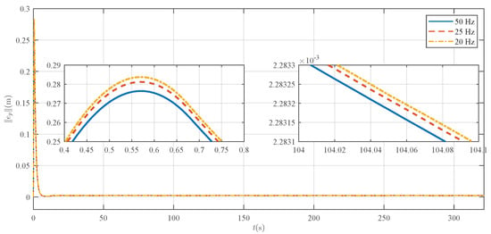
Figure 15.
Comparison of the tracking errors under different controller sampling frequencies.
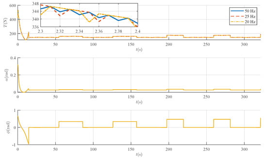
Figure 16.
Comparison of the control inputs under different controller sampling frequencies.
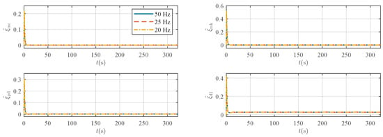
Figure 17.
Comparison of the estimated parameters under different controller sampling frequencies.
The quantitative results from Figure 15 and Table 4 indicate that the trajectory tracking error gradually increases as the sampling frequency is reduced. This observation is corroborated by the deviation in the adaptive parameter trajectories under discretization when compared to the continuous-time benchmark (Figure 14 and Figure 17).

Table 4.
Tracking errors under continuous-time control and different sampling frequencies.
Nevertheless, it is crucial to emphasize that despite this slight performance degradation at lower frequencies, the proposed P-RAC maintains system stability and shows robust performance. Across the range of sampling frequencies typically employed in practical flight control (as detailed in Table 4), the maximum tracking error remains below , and the RMSE is kept about . This stands in contrast to many conventional high-performance controllers, such as sliding mode control, which often rely heavily on high sampling frequencies. This result demonstrates the resilience and adaptability of the P-RAC to computational constraints, underscoring its practical value for deployment on small UAV platforms with limited hardware resources.
6. Conclusions
This paper has proposed a robust adaptive control framework for trajectory tracking of fixed-wing UAVs subject to nonlinear dynamics, parametric uncertainties, and external disturbances. The framework employs a cascaded architecture based on a kinematic/dynamic decomposition that serves as an intermediate layer to decouple high-level trajectory planning from low-level flight control. Central to this architecture is a backstepping-based robust adaptive controller designed to operate directly on the nonlinear system model. The controller incorporates a structured uncertainty modeling method, utilizing adaptive laws to estimate unknown parameters in state-dependent uncertainty norm bounds online, and integrates a boundary layer technique to suppress control chattering. These features ensure that the closed-loop tracking error is ultimately bounded and converges to an arbitrarily small neighborhood of zero.
Numerical simulations show the tracking performance and robustness of the proposed method in the presence of parametric uncertainties and external wind disturbances. While these results are promising, key limitations point towards necessary future work. The controller’s robustness requires further validation under more complex disturbance conditions beyond the synthesized model used. Furthermore, addressing potential model mismatch between the point-mass design and full aircraft dynamics, particularly the integration with a real attitude controller, underscores the need for experimental validation on a physical UAV platform, which remains a primary focus for future work. Additionally, future research could include extensive comparisons with other control methods and the extension to cooperative multi-UAV control.
Author Contributions
Conceptualization, Y.S.; methodology, Y.S.; software, Y.S. and D.H.; validation, Y.S. and Y.Z.; writing—original draft preparation, Y.S.; writing—review and editing, Z.S. and Y.Z.; supervision, Y.Z. All authors have read and agreed to the published version of the manuscript.
Funding
This work was supported by the National Natural Science Foundation of China under Grants U24B20173 and 62573016.
Data Availability Statement
All data supporting the findings of this study are included within the article.
Conflicts of Interest
The authors declare no conflicts of interest.
References
- Lyu, M.; Zhao, Y.; Huang, C.; Huang, H. Unmanned aerial vehicles for search and rescue: A survey. Remote Sens. 2023, 15, 3266. [Google Scholar] [CrossRef]
- Li, J.; Zhang, G.; Jiang, C.; Zhang, W. A survey of maritime unmanned search system: Theory, applications and future directions. Ocean. Eng. 2023, 285, 115359. [Google Scholar] [CrossRef]
- Zhang, Z.; He, C.; Chen, H.; Zhang, Y.; Wang, H.; Cai, Y.; Chen, L.; Li, H.; Lu, T. Small fixed-wing unmanned aerial vehicle path following under low altitude wind shear disturbance. IEEE Trans. Intell. Transp. Syst. 2024, 25, 13991–14003. [Google Scholar] [CrossRef]
- Chen, Y.; Li, N.; Wu, Y.; Zeng, W. Horizontal path following kinematic controller for a small fixed-wing UAV using backstepping and parameter optimization. Int. J. Control Autom. Syst. 2023, 21, 1005–1019. [Google Scholar] [CrossRef]
- Yang, J.; Liu, C.; Coombes, M.; Yan, Y.; Chen, W.H. Optimal path following for small fixed-wing UAVs under wind disturbances. IEEE Trans. ControlSyst. Technol. 2021, 29, 996–1008. [Google Scholar] [CrossRef]
- Zhao, S.; Wang, X.; Zhang, D.; Shen, L. Curved path following control for fixed-wing unmanned aerial vehicles with control constraint. J. Intell. Robot. Syst. 2018, 89, 107–119. [Google Scholar] [CrossRef]
- Beard, R.W.; Ferrin, J.; Humpherys, J. Fixed wing UAV path following in wind with input constraints. IEEE Trans. Intell. Transp. Syst. 2014, 22, 2103–2117. [Google Scholar] [CrossRef]
- Liu, C.; McAree, O.; Chen, W.H. Path-following control for small fixed-wing unmanned aerial vehicles under wind disturbances. Int. J. Robust Nonlinear Control 2013, 23, 1682–1698. [Google Scholar] [CrossRef]
- Wu, W.; Wang, Y.; Gong, C.; Ma, D. Path following control for miniature fixed-wing unmanned aerial vehicles under uncertainties and disturbances: A two-layered framework. Nonlinear Dyn. 2022, 108, 3761–3781. [Google Scholar] [CrossRef]
- Wu, W.; Xu, J.; Gong, C.; Cui, N. Adaptive path following control for miniature unmanned aerial vehicle confined to three-dimensional dubins path: From take-off to landing. ISA Trans. 2023, 143, 156–167. [Google Scholar] [CrossRef]
- Zhao, S.; Wang, X.; Lin, Z.; Zhang, D.; Shen, L. Integrating vector field approach and input-to-state stability curved path following for unmanned aerial vehicles. IEEE Trans. Syst. Man Cybern.-Syst. 2020, 50, 2897–2904. [Google Scholar] [CrossRef]
- Zheng, Z.; Li, J.; Guan, Z.; Zuo, Z. Constrained moving path following control for UAV with robust control barrier function. IEEE/CAA J. Autom. Sin. 2023, 10, 1557–1570. [Google Scholar] [CrossRef]
- Lu, H.; Gao, L.; Yan, Y.; Hou, M.; Wang, C. Wind disturbance compensated path-following control for fixed-wing UAVs in arbitrarily strong winds. Chin. J. Aeronaut. 2024, 37, 431–445. [Google Scholar] [CrossRef]
- Wang, Z.; Gong, Z.; Xu, J.; Wu, J.; Liu, M. Path following for unmanned combat aerial vehicles using three-dimensional nonlinear guidance. IEEE/ASME Trans. Mechatron. 2022, 27, 2646–2656. [Google Scholar] [CrossRef]
- Zhao, Y.; Tsiotras, P. Time-optimal path following for fixed-wing aircraft. J. Guid. Control. Dyn. 2013, 36, 83–95. [Google Scholar] [CrossRef][Green Version]
- Nian, X.H.; Zhou, W.X.; Li, S.L.; Wu, H.Y. 2-D path following for fixed wing UAV using global fast terminal sliding mode control. ISA Trans. 2023, 136, 162–172. [Google Scholar] [CrossRef]
- Kaminer, I.; Pascoal, A.; Xargay, E.; Hovakimyan, N.; Cao, C.; Dobrokhodov, V. Path following for small unmanned aerial vehicles using L1 adaptive augmentation of commercial autopilots. J. Guid. Control Dyn. 2010, 33, 550–564. [Google Scholar] [CrossRef]
- Galffy, A.; Boeck, M.; Kugi, A. Nonlinear 3D path following control of a fixed-wing aircraft based on acceleration control. Control. Eng. Pract. 2019, 86, 56–69. [Google Scholar] [CrossRef]
- Yang, K.; Kang, Y.; Sukkarieh, S. Adaptive nonlinear model predictive path-following control for a fixed-wing unmanned aerial vehicle. Int. J. Control Autom. Syst. 2013, 11, 65–74. [Google Scholar] [CrossRef]
- Sujit, P.B.; Saripalli, S.; Sousa, J.B. Unmanned aerial vehicle path following a survey and analysis of algorithms for fixed-wing unmanned aerial vehicles. IEEE Control Syst. Mag. 2014, 34, 42–59. [Google Scholar] [CrossRef]
- Beard, R.W.; McLain, T.W. Small Unmanned Aircraft: Theory and Practice; Princeton University Press: Princeton, NJ, USA, 2012. [Google Scholar]
- Yan, Y.; Liu, C.; Oh, H.; Chen, W.H. Dual-layer optimization-based control allocation for a fixed-wing UAV. Aerosp. Sci. Technol. 2021, 119, 107184. [Google Scholar] [CrossRef]
- Cheng, Z.K.; Yang, J.Y.; Sun, Y.; Zhao, L.Y.; Zhao, L. State predictor-based deep model reference adaptive control for quadrotor trajectory tracking. Aerosp. Sci. Technol. 2025, 157, 109868. [Google Scholar] [CrossRef]
- Chen, L.L.; Liu, Z.B.; Dang, Q.Q.; Zhao, W.; Wang, G.D. Robust trajectory tracking control for a quadrotor using recursive sliding mode control and nonlinear extended state observer. Aerosp. Sci. Technol. 2022, 128, 107749. [Google Scholar] [CrossRef]
- Liu, H.; Li, D.; Zuo, Z.; Zhong, Y. Robust three-loop trajectory tracking control for quadrotors with multiple uncertainties. IEEE Trans. Ind. Electron. 2016, 63, 2263–2274. [Google Scholar] [CrossRef]
- Li, S.B.; Durdevic, P.; Yang, Z.Y. Trajectory tracking of underactuated vtol aerial vehicles with unknown system parameters via irl. IEEE Trans. Autom. Control 2022, 67, 3043–3050. [Google Scholar] [CrossRef]
- Liu, D.Y.; Liu, H.; Lewis, F.L. Robust trajectory tracking control for unmanned tail-sitters in aggressive flight mode transitions. Int. J. Robust Nonlinear Control 2019, 29, 4270–4284. [Google Scholar] [CrossRef]
- Cardoso, D.N.; Esteban, S.; Raffo, G.V. A new robust adaptive mixing control for trajectory tracking with improved forward flight of a tilt-rotor UAV. ISA Trans. 2021, 110, 86–104. [Google Scholar] [CrossRef]
- Liu, H.; Yu, Y.; Zhong, Y.S. Robust trajectory tracking control for a laboratory helicopter. Nonlinear Dyn. 2014, 77, 621–634. [Google Scholar] [CrossRef]
- Li, S.L.; Liu, H.; Shi, Z.Y.; Zhong, Y.S. Monocular camera based trajectory tracking of 3-dof helicopter. Asian J. Control 2014, 16, 742–751. [Google Scholar] [CrossRef]
- Zhang, Z.; Zhang, K.; Han, Z. Three-dimensional nonlinear trajectory tracking control based on adaptive sliding mode. Aerosp. Sci. Technol. 2022, 128, 107734. [Google Scholar] [CrossRef]
- Liu, D.; Liu, H.; Valavanis, K.P. Fully distributed time-varying formation control for multiple uncertain missiles. IEEE Trans. Aerosp. Electron. Syst. 2020, 57, 1646–1656. [Google Scholar] [CrossRef]
- Kai, J.M.; Hamel, T.; Samson, C. A unified approach to fixed-wing aircraft path following guidance and control. Automatica 2019, 108, 108491. [Google Scholar] [CrossRef]
- Ren, W.; Beard, R.W. Trajectory tracking for unmanned air vehicles with velocity and heading rate constraints. IEEE Trans. Control Syst. Technol. 2004, 12, 706–716. [Google Scholar] [CrossRef]
- Ren, W. Trajectory tracking control for a miniature fixed-wing unmanned air vehicle. Int. J. Syst. Sci. 2007, 38, 361–368. [Google Scholar] [CrossRef]
- Rao, D.M.K.K.V.; Go, T.H. Optimization, stability analysis, and trajectory tracking of perching maneuvers. J. Guid. Control Dyn. 2014, 37, 879–888. [Google Scholar] [CrossRef]
- Brezoescu, A.; Lozano, R.; Castillo, P. Lyapunov-based trajectory tracking controller for a fixed-wing unmanned aerial vehicle in the presence of wind. Int. J. Adapt. Control. Signal Process. 2015, 29, 372–384. [Google Scholar] [CrossRef]
- Grymin, D.J.; Farhood, M. Two-step system identification and trajectory tracking control of a small fixed-wing UAV. J. Intell. Robot. Syst. 2016, 83, 105–131. [Google Scholar] [CrossRef]
- Gavilan, F.; Vazquez, R.; Esteban, S. Trajectory tracking for fixed-wing UAV using model predictive control and adaptive backstepping. IFAC 2015, 48, 132–137. [Google Scholar] [CrossRef]
- Li, Y.; Zhang, L.; Wu, T.; Han, Y.; Zhang, Y. Switched model-predictive-control-based trajectory tracking of fixed-wing aircraft for payload dropping. J. Guid. Control. Dyn. 2024, 48, 1–9. [Google Scholar] [CrossRef]
- Xu, Y.; Zhou, R.; Yu, Z.; Chen, F.; Zhang, Y. Barrier Lyapunov function-based finite-time reliable trajectory tracking control of fixed-wing UAV with error constraints. IFAC 2022, 55, 597–602. [Google Scholar] [CrossRef]
- Xu, L.; Qi, G. Function observer based on model compensation control for a fixed-wing UAV. Aerosp. Sci. Technol. 2024, 152, 109325. [Google Scholar] [CrossRef]
- Zhao, S.; Zheng, J.; Yi, F.; Wang, X.; Zuo, Z. Exponential predefined time trajectory tracking control for fixed-wing UAV with input saturation. IEEE Trans. Aerosp. Electron. Syst. 2024, 60, 6406–6419. [Google Scholar] [CrossRef]
- Zhong, Y.S. Robust output tracking control of SISO plants with multiple operating points and with parametric and unstructured uncertainties. Int. J. Control 2002, 75, 219–241. [Google Scholar] [CrossRef]
- Zhang, Z.; Yang, W.; Shi, Z.; Zhong, Y. A novel robust finite-time stable trajectory tracking scheme for fixed wing unmanned aerial vehicles. In Proceedings of the 2021 40th Chinese Control Conference (CCC), Shanghai, China, 26–28 July 2021; pp. 7790–7796. [Google Scholar]
- Yang, W.; Zhang, Z.; Shi, Z.; Zhong, Y. Design and experimental validation of a robust trajectory tracking control scheme for small fixed-wing unmanned aerial vehicles. In Proceedings of the 2021 IEEE International Conference on Systems, Man, and Cybernetics (SMC), Melbourne, Australia, 17–20 October 2021; pp. 727–732. [Google Scholar] [CrossRef]
- Yang, W.; Chen, J.; Zhang, Z.; Shi, Z.; Zhong, Y. Robust cascaded horizontal-plane trajectory tracking for fixed-wing unmanned aerial vehicles. J. Frankl. Inst.-Eng. Appl. Math. 2022, 359, 1083–1112. [Google Scholar] [CrossRef]
- Yang, W.; Shi, Z.; Zhong, Y. Robust adaptive three-dimensional trajectory tracking control scheme design for small fixed-wing UAVs. ISA Trans. 2023, 141, 377–391. [Google Scholar] [CrossRef] [PubMed]
- Wheeler, G.; Su, C.Y.; Stepanenko, Y. A sliding mode controller with improved adaptation laws for the upper bounds on the norm of uncertainties. Automatica 1998, 34, 1657–1661. [Google Scholar] [CrossRef]
- Siouris, G.M. Missile Guidance and Control Systems; Springer Science & Business Media: New York, NY, USA, 2004. [Google Scholar]
- Abdallah, L.; Khardi, S.; Haddou, M. Optimization of operational aircraft parameters reducing noise emission. Appl. Math. Sci. 2010, 4, 515–535. [Google Scholar]
- Ringertz, U. Optimal trajectory for a minimum fuel turn. J. Aircr. 2000, 37, 932–934. [Google Scholar] [CrossRef]
- Khardi, S. Aircraft shortest and fastest continuous descent approach development. J. Aircr. 2012, 49, 1931–1939. [Google Scholar] [CrossRef]
- Lone, M.; Lai, C.K.; Cooke, A.; Whidborne, J. Framework for flight loads analysis of trajectory-based manoeuvres with pilot models. J. Aircr. 2014, 51, 637–650. [Google Scholar] [CrossRef]
Disclaimer/Publisher’s Note: The statements, opinions and data contained in all publications are solely those of the individual author(s) and contributor(s) and not of MDPI and/or the editor(s). MDPI and/or the editor(s) disclaim responsibility for any injury to people or property resulting from any ideas, methods, instructions or products referred to in the content. |
© 2025 by the authors. Licensee MDPI, Basel, Switzerland. This article is an open access article distributed under the terms and conditions of the Creative Commons Attribution (CC BY) license (https://creativecommons.org/licenses/by/4.0/).